1
Managed Connected Router 4G and WiFi
MDS 05-6628A01, Rev. A
June 2013
Preliminary
Installation Technical
and Operation
Guide
Manual
MDSTM Orbit MCR-4G
Quick-Start instructions for this product are contained in publication 05-6702A01.
Visit our website for downloadable copies of all documentation at www.gemds.com.
TABLE OF CONTENTS
1.0 INTRODUCTION ...........................................................................................................................1
1.1 About This Manual .................................................................................................................................. 1
Software Command Notations .................................................................................................................. 1
Authorized Features Icon .......................................................................................................................... 2
2.0 PRODUCT DESCRIPTION............................................................................................................3
2.1
2.2
2.3
2.4
Key Features ............................................................................................................................................ 3
Interface Types ........................................................................................................................................ 3
Typical Application ................................................................................................................................. 3
Connectors and Indicators ....................................................................................................................... 4
Grounding Considerations ........................................................................................................................ 9
Mounting Options ..................................................................................................................................... 9
Optional DIN Rail Mounting .................................................................................................................... 9
Antenna Planning & Installation ........................................................................................................... 10
Accessories and Spares ........................................................................................................................... 12
3.0 Device Management ......................................................................................................................13
3.1 Connecting a PC .................................................................................................................................... 13
Differences Between Serial & SSH ........................................................................................................ 13
Establishing Communication—Serial Interface...................................................................................... 13
Setting Basic Parameters—First Steps.................................................................................................... 14
One-Time “Recovery” Passwords........................................................................................................... 14
3.2 Pre-Configured Settings ........................................................................................................................ 16
3.3 YANG Interface ..................................................................................................................................... 16
CLI Login Prompt ................................................................................................................................... 17
3.4 Operational Topic Areas......................................................................................................................... 23
Serial Console ...................................................................................................................... 24
Network ................................................................................................................................ 25
LAN ...................................................................................................................................... 26
VLAN Operation ................................................................................................................... 28
Cell ....................................................................................................................................... 29
WiFi ...................................................................................................................................... 32
Bridging ................................................................................................................................ 37
Routing ................................................................................................................................. 40
Firewall and NAT.................................................................................................................. 41
VPN ...................................................................................................................................... 50
DNS ...................................................................................................................................... 57
DHCP Service ...................................................................................................................... 58
Iperf Service ......................................................................................................................... 61
Date, time and NTP.............................................................................................................. 62
Geographical-location .......................................................................................................... 63
User Management and Access Controls.............................................................................. 64
Login-Lockout....................................................................................................................... 66
RADIUS................................................................................................................................ 67
MDS 05-6628A01, Rev. A
MDS Orbit MCR-4G Technical Manual
i
File Servers .......................................................................................................................... 68
Certificate Management ....................................................................................................... 69
Event Logging ...................................................................................................................... 77
Firmware Management ........................................................................................................ 78
Support Bundle .................................................................................................................... 80
4.0 Technical Reference ........................................................................................................81
4.1 Troubleshooting ..................................................................................................................................... 81
LED Status Indicators ............................................................................................................................. 81
4.2 Specifications ........................................................................................................................................ 82
4.3 Agency/Regulatory Approvals .............................................................................................................. 82
4.4 Glossary of Terms & Abbreviations ...................................................................................................... 82
5.0
APPENDIX A – Data Configuration Tree ...................................................................................85
6.0 APPENDIX B – Command Line Interface (CLI) Features .........................................................101
7.0 APPENDIX C – Integrity Measurement Authority (IMA) .........................................................115
8.0 APPENDIX G – Licenses............................................................................................................125
Copyright and Trademark
This manual and all software described herein is protected by Copyright: 2013 GE MDS, LLC. All
rights reserved. GE MDS, LLC reserves its right to correct any errors and omissions in this publication.
RF Safety Notice (English and French)
RF Exposure
l'exposition aux RF
ii
Concentrated energy from a directional antenna may pose a health hazard to
humans. Do not allow people to come closer to the antenna than the distances
listed in the table below when the transmitter is operating. More information on
RF exposure can be found online at the following website:
www.fcc.gov/oet/info/documents/bulletins.
Concentré d'énergie à partir d'une antenne directionnelle peut poser un risque
pour la santé humaine. Ne pas permettre aux gens de se rapprocher de l'antenne
que les distances indiquées dans le tableau ci-dessous lorsque l'émetteur est en
marche. Plus d'informations sur l'exposition aux RF peut être trouvé en ligne à
l'adresse suivante: www.fcc.gov / oet / info / documents et bulletins.
MDS Orbit MCR-4G Technical Manual
MDS 05-6628A01, Rev. A
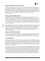
Antennas must not be co-located. All transmission antennas must be at least 20 cm apart to comply
with FCC co-location rules.
Orbit Device vs. Minimum RF Safety Distance
Minimum Safety Distance
from Antenna
Radio Module Type
MCR-4G
20 cm
MCR-900
23 cm
Other models
Consult factory prior to operation.
FCC Part 15 Notice
Operation is subject to the following two conditions: (1) this device may not cause harmful interference, and (2) this device must accept any interference received, including interference that may
cause undesired operation. Any unauthorized modification or changes to this device without the
express approval of the manufacturer may void the user’s authority to operate this device. Furthermore, this device is intended to be used only when installed in accordance with the instructions outlined in this manual. Failure to comply with these instructions may void the user’s authority to
operate this device.
Industry Canada Notice
This Class A digital apparatus complies with Canadian ICES-003.
Cet appareil numérique de la classe A est conforme à la norme NMB-003 du Canada.
Operational Safety Notices
The MDS Orbit MCR-4G may not be used in an environment where radio frequency equipment is
prohibited or restricted in its use. This typically includes aircrafts, airports, hospitals, and other sensitive electronic areas.
Do not operate RF devices in an environment that may be susceptible to radio interference
resulting in danger, specifically:
• Areas where prohibited by law
Follow any special rules and regulations and obey all signs and notices. Do not use the MCR-4G
when you suspect that it may cause interference or danger.
• Near Medical and life support equipment
Do not use the MCR-4G in any area where medical equipment, or life support equipment may be
located, or near any equipment that may be susceptible to any form of radio interference.
MDS 05-6628A01, Rev. A
MDS Orbit MCR-4G Technical Manual
iii
Cellular Operational Bands
The following table shows the bands in which the cellular module operates for each wireless technology.
FCC IDs of Installed Transmitters
As of the date of printing, the following FCC identifiers are assigned to the modules listed below.
For the latest, official listings of all agency approval information, please contact your factory representative.
CELL Modem FCC ID: PKRNVWE362, IC ID: 3229B:E362
WIFI Module FCC ID: M4Y-ZCN722MV1, IC ID 3195A-ZCN722MV1
CE Mark and RTTE Notice
This product, using the "WIFI internal radio module" only, is CE marked and compliant with the
RTTE directive. Other configurations will be added for EU use in future releases.
Servicing Precautions
When servicing energized equipment, be sure to wear appropriate Personal Protective Equipment
(PPE). During internal service, situations could arise where objects accidentally contact or short
circuit components and the appropriate PPE would alleviate or decrease the severity of potential
injury. When servicing radios, all workplace regulations and other applicable standards for live
electrical work should be followed to ensure personal safety.
iv
MDS Orbit MCR-4G Technical Manual
MDS 05-6628A01, Rev. A
Manual Revision and Accuracy
This manual was prepared to cover a specific version of firmware code. Accordingly, some screens
and features may differ from the actual unit you are working with. While every reasonable effort
has been made to ensure the accuracy of this publication, product improvements may also result in
minor differences between the manual and the product shipped to you. If you have additional questions or need an exact specification for a product, please contact GE MDS using the information at
the back of this guide. In addition, manual updates can be found on our web site at
www.gemds.com
Environmental Information
The manufacture of this equipment has required the extraction and use of natural resources.
Improper disposal may contaminate the environment and present a health risk due to hazardous
substances contained within. To avoid dissemination of these substances into our environment, and
to limit the demand on natural resources, we encourage you to use the appropriate recycling systems for disposal. These systems will reuse or recycle most of the materials found in this equipment
in a sound way. Please contact GE MDS or your supplier for more information on the proper disposal of this equipment.
Battery Disposal—This product may contain a battery. Batteries must be disposed of properly, and
may not be disposed of as unsorted municipal waste in the European Union. See the product documentation for specific battery information. Batteries are marked with a symbol, which may
include lettering to indicate cadmium (Cd), lead (Pb), or mercury (Hg). For proper recycling return
the battery to your supplier or to a designated collection point. For more information see:
www.weeerohsinfo.com.
Product Test Data Sheets
Test Data Sheets showing the original factory test results for this unit are available upon request
from the GE MDS Quality Leader. Contact the factory using the information at the back of this
manual. Serial numbers must be provided for each product where a Test Data Sheet is required.
CSA/us Notice
This product is approved for use in Class 1, Division 2, Groups A, B, C & D Hazardous Locations.
Such locations are defined in Article 500 of the National Fire Protection Association (NFPA) publication NFPA 70, otherwise known as the National Electrical Code. The transceiver has been recognized for use in these hazardous locations by the Canadian Standards Association (CSA) which
also issues the US mark of approval (CSA/US). The CSA Certification is in accordance with CSA
STD C22.2 No. 213-M1987.
CSA Conditions of Approval: The transceiver is not acceptable as a stand-alone unit for use in the
hazardous locations described above. It must either be mounted within another piece of equipment
which is certified for hazardous locations, or installed within guidelines, or conditions of approval,
as set forth by the approving agencies. These conditions of approval are as follows: The transceiver
must be mounted within a separate enclosure which is suitable for the intended application.The
antenna feedline, DC power cable and interface cable must be routed through conduit in accordance with the National Electrical Code. Installation, operation and maintenance of the transceiver
MDS 05-6628A01, Rev. A
MDS Orbit MCR-4G Technical Manual
v
should be in accordance with the transceiver's installation manual, and the National Electrical
Code. Tampering or replacement with non-factory components may adversely affect the safe
use of the transceiver in hazardous locations, and may void the approval. A power connector
with screw-type retaining screws as supplied by GE MDS must be used.
EXPLOSION
HAZARD!
vi
Do not disconnect equipment unless power has been switched off or the area is known to
be non-hazardous. Refer to Articles 500 through 502 of the National Electrical Code
(NFPA 70) for further information on hazardous locations and approved Division 2 wiring
methods.
MDS Orbit MCR-4G Technical Manual
MDS 05-6628A01, Rev. A
1.0
INTRODUCTION
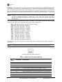
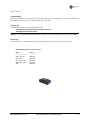
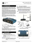
This manual describes the MDS Orbit MCR-4G (Managed Connected Router) shown in Figure 1. The unit
is a highly secure, industrial grade, wireless communication product for broad based applications including
control center monitoring, well site pad operations, and video surveillance. It serves the need for localized
WiFi communications with a cellular back-up or backhaul option, while providing the extended temperature
range and industrial-grade packaging inherent to GE MDS products. These features allow the best use of
communication options at each installation site.
Figure 1. MCR-4G Unit
(Standard 2E1S configuration shown)
With a common hardware architecture and user interface, the MCR offers flexibility in network design and
application, with simplified training, maintenance, and deployment costs. GE MDS provides an array of
communication products with multiple interface options and a variety of enclosures to give customers the
choice and flexibility to design their communications network to meet geographic and industry specific
challenges. Information on other GE MDS products can be found by visiting our website at
www.gemds.com.
1.1 About This Manual
This manual is intended for systems engineers, network administrators, and others responsible for planning,
commissioning, using, and troubleshooting the wireless system. Installation steps are not included in this
publication. For installation instructions, refer to the MCR-4G Setup Guide, part no. 05-6702A01. Electronic copies of all user documentation are available free of charge at www.gemds.com.
The MCR-4G Setup Guide, Part no. 05-6702A01,
contains installation instructions, as well as basic
startup information for this product.
All GE MDS user manuals and updates are available
online at www.gemds.com.
1.1.1 Software Command Notations
The product is designed for software control via a connected PC. As such, there are no external controls or
adjustments present. To show the names of software commands, keyboard entries, or other information displayed on a PC screen, a bolded font is used throughout the manual. In the case of tabular data displayed on
a PC screen, a variation on this font is used to maintain proper layout. (See examples that follow.)
MDS 05-6628A01, Rev. A
MDS Orbit MCR-4G Technical Manual
1
Bolded font example (used for software commands and keyboard entries)
Bolded font example (used for tabular screen data)
In the Device Management section, there are a number of command strings where information is presented
by the unit, and a reply is required from the user. In such cases, information from the unit is shown in a
non-bolded font, and the user response is shown in bold. For example:
(none) login: admin
Further, in some cases, command lines will be shown with non-bolded, italicized text contained within the
string. Such text indicates the need for user-supplied parameters, such as the name of an item. For example:
set interfaces interface myBridge virtual‐type bridge
In the above example, you would enter the specific name of your bridge to complete the command line entry.
NOTE: The software commands and responses shown in this manual were obtained from a unit operating
in a lab environment. The information displayed may differ from field service conditions.
1.1.2 Authorized Features Icon
Some product features are dependent on purchased options and applicable regulatory constraints. A “key”
icon
appears near the heading of any such features.
2
MDS Orbit MCR-4G Technical Manual
MDS 05-6628A01, Rev. A
2.0
PRODUCT DESCRIPTION
The MCR-4G is a rugged networking router providing comprehensive solutions for IP/Ethernet, serial, and
machine-to-machine wireless communication. This industrial package provides integrated 4G LTE wireless
technology and connectivity for Ethernet and serial devices requiring secure operation.
2.1 Key Features
MCR units include the following key features:
• Security—The unit uses industry-leading security features to protect data while maintaining compatibility with deployed infrastructures. Features include AAA user access with passwords and lockout protection, VPNs, encrypted storage, signed firmware, secure booting, integrity management,
and more.
• Small Form Factor—The unit is housed in a rugged enclosure suited for operation in harsh industrial environments. It requires only protection from direct exposure to the weather, and may be easily
mounted inside a NEMA enclosure for outdoor applications when required.
• Network Interfaces—Several network interfaces are present to provide connectivity for a variety
of equipment and applications. Ethernet, serial, and WiFi interfaces provide local connections while
a cellular interface provides access to public carrier networks.
• User interface—Multiple user interfaces are provided for configuration and monitoring of the unit.
These include local serial console, web, SSH, USB, and NETCONF.
NOTE: When the unit is installed in hazardous locations, use only the serial or Ethernet connections on
the unit’s front panel. Do not use the USB port in hazardous locations.
• NETCONF—A next-generation management protocol is used that provides an array of features for
device configuration and monitoring.
• Network Management System—The PulseNET Network Management System allows administering and monitoring the operation of small-to-large scale deployments.
2.2 Interface Types
MCR units are offered in two external interface offerings; 2 Ethernet/1 Serial (2E1S), or 2 Serial/1 Ethernet
(2S1E). The 2E1S configuration (Figure 1) is the standard model and is the focus of this manual. Most information applies equally to both configurations, however.
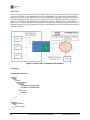
2.3 Typical Application
The unit provides flexibility in network communications and may be used in a wide variety of applications.
In a common scenario, it provides cellular connectivity to locally-connected devices that are located on a
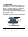
local/internal/private LAN or WiFi network. The unit acts as an Access Point on the WiFi interface to provide connectivity to WiFi clients. Figure 2 shows an example network in which the unit provides connectivity to multiple end devices. The end devices are connected via Ethernet, serial, and WiFi links.
MDS 05-6628A01, Rev. A
MDS Orbit MCR-4G Technical Manual
3
Invisible place holder
Figure 2. Typical MCR Application
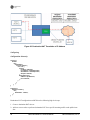
2.4 Connectors and Indicators
Figure 3 shows the unit’s front panel connectors and indicators. These items are referenced in the
text that follows. The unit’s LED Indicator Panel is described in Table 4 on Page 8.
LED Indicator
Panel
Mini USB
Port
DC Power
(10-60 Vdc)
Ethernet Ports
(RJ-45 10/100)
COM Port
Cellular
Antennas
(Aux & Main)
SIM Card
Slot
WiFi Antenna
Figure 3. Connectors and Indicators
(2E1S configuration shown)
4
MDS Orbit MCR-4G Technical Manual
MDS 05-6628A01, Rev. A
PWR—Two-conductor DC input connection. Input voltage must be well filtered, and within the range of
10-60 Vdc. The power supply must be capable of providing a maximum of 15 watts. The unit includes a
6-foot (1.83 meter) power cable suitable for indoor or outdoor use when properly connected. The DC power
connector (Figure 4) is keyed, and can only be inserted one way.
Invisible place holder
Lead
Binding
Screws (2)
Retaining
Screws (2)
Wire Ports (2)
(Polarity: Left +, Right –)
Figure 4. DC Power Connector (P/N 73-1194A39)
NOTE: The unit is designed for use in negative ground systems only.
ETH1 / ETH2— Ethernet connection port. These ports support both device management and payload data
transport. Depending on product version, the unit may have one or two Ethernet ports. This is a standard
RJ-45 jack, and features MDIX auto-sensing capability, allowing straight-through or crossover cables to be
used.
Connecting to the unit via SSH supports device management and provides the same user interface available
using the unit’s COM1 serial port. Various options are available for passing Ethernet data, allowing system
administrators to optimize the configuration for maximum efficiency, based on the system’s operating characteristics.
(As viewed from the outside of the unit)
Table 1. ETH1/2 Pin Details
Pin
Function
1
Transmit Data (TX) High
2
Transmit Data (TX) Low
3
Receive Data (RX) High
4
Unused
5
Unused
6
Receive Data (RX) Low
7
Unused
8
Unused
USB Port—This port allows for connection of a laptop or PC. The port provides a local console for management of the device. A standard host-to-mini device USB 2.0 cable may be used.
MDS 05-6628A01, Rev. A
MDS Orbit MCR-4G Technical Manual
5
COM Port—This connector serves as the serial interface port for both console management and payload
data. It allows for connection of data equipment in the common Serial signaling standard. By default, the
port is enabled for local console control. The COM port serves as the primary interface for connecting the
unit to an external DTE serial device supporting the RS-232 or RS-485 serial data format. If necessary, an
adapter may be used to convert the unit’s RJ-45 serial jack to a DB-9F type (GE MDS part no. 73-2434A12).
NOTE: Not all PCs include a serial port. If one is not available, the unit’s USB port may be used to access
the device management interface. Alternatively, a PC’s USB port may be used with a
USB-to-Serial adapter and appropriate driver software. These devices are available from several
manufacturers.
The COM port supports a serial data rate of 1200-115200 bps (115200 default, asynchronous only). The unit
is hardwired as a DCE device. Supported data formats for the COM port are:
8N1 - 8 char bits, no parity, 1 stop bit (Default setting)
8N2 - 8 char bits, no parity, 2 stop bits
8O1 - 8 char bits, odd parity, 1 stop bit
8O2 - 8 char bits, odd parity, 2 stop bits
8E1 - 8 char bits, even parity, 1 stop bit
8E2 - 8 char bits, even parity, 2 stop bits
7N1 - 7 char bits, no parity, 1 stop bit
7N2 - 7 char bits, no parity, 2 stop bits
7O1 - 7 char bits, odd parity, 1 stop bit
7O2 - 7 char bits, odd parity, 2 stop bits
7E1 - 7 char bits, even parity, 1 stop bit
7E2 - 7 char bits, even parity, 2 stop bits.
The tables below provide pin descriptions for the COM1 data port in RS-232 mode and RS-485 modes,
respectively.
NOTE: The COM2 port, if present, is restricted to RS-232 mode; it cannot be used for RS-485.
(As viewed from the outside of the unit)
Table 2. COM1/2 Port Pin Details (RS-232)
6
Pin
Number
Input/Output
Pin Description
1
Reserved
2
OUT
3
Reserved
4
Ground
Connects to ground (negative supply potential) on chassis
5
OUT
RXD (Received Data)—Supplies received data to the connected device
6
IN
TXD (Transmitted Data)—Accepts TX data from the connected device
7
OUT
CTS (Clear to Send)
8
IN
RTS (Ready to Send)
DCD (Data Carrier Detect)
MDS Orbit MCR-4G Technical Manual
MDS 05-6628A01, Rev. A
Table 3. COM1 Port Pin Details (RS-485)
Pin
Number
Input/Output
Pin Description
1
Reserved
2
OUT
3
Reserved
4
Ground
Connects to ground (negative supply potential) on chassis
5
OUT
TXD+ (Transmitted Data +)—Non-inverting driver output. Supplies
received payload data to the connected device.
6
IN
RXD+ (Received Data +)— Non-inverting receiver input. Accepts
payload data from the connected device.
7
OUT
TX-/TXB (Transmitted Data -)—Inverting driver output
8
IN
RX-/RXB (Received Data -)— Inverting receiver input
DCD (Data Carrier Detect)
COM1 Port notes and wiring arrangements (RS-485):
The COM1 port supports 4-wire and 2-wire RS-485 mode.
·
RXD+ / RXB and RXD– / RXA are data sent into the unit
·
RXD+ / RXB is positive with respect to RXD– / RXA when the line input is a “0”
·
TXD+ / TXB and TXD– / TXA are data sent out by the unit
·
TXD+ / TXB is positive with respect to the TXD– / TXA when the line output is a “0”
Cell Antennas (AUX and MAIN)—These SMA coaxial connectors are for attachment of cellular antennas.
The MAIN connection is for basic cellular transmission/reception, and the AUX connector is for attachment
of a receive-only antenna which provides for MIMO receive operation (diversity) with standard for 4G modules, improving signal quality in many installations. In general, both antennas should always be used for
cellular operation. The GE MDS part number for this antenna type is 97-2485A04.
Figure 5. Directly-Connected Cellular Antenna (Typical)
(GE MDS Part No. 97-2485A04)
MDS 05-6628A01, Rev. A
MDS Orbit MCR-4G Technical Manual
7
WiFi Antenna—Antenna connection for 2400 MHz WiFi service. The connector appears similar to the cellular connectors discussed above, but is a Reverse-SMA type. It contains a pin that matches with an SMA-F
connector. The GE MDS part number for this antenna is 97-4278A48.
SIM Port—This port accepts a mini SIM card (2FF type) for 4G cell operation. The unit’s cellular interface
will not function without a valid SIM card installed. The customer is responsible for obtaining a provisioned
SIM card for the appropriate service plan from their cellular provider.
CAUTION: Do not insert the SIM card when the unit is powered on.
Card Insertion: The SIM card only inserts one way; do not force it. It should be oriented with the printed
label facing up, and the cut-off corner on the left side. This side is inserted first. A small instrument, such
as a flathead screwdriver, may be helpful to gently push the SIM all the way in until it locks.
Information on determining the cell module’s IMSI/IMEI (typically required for provisioning) is provided
on Page 31 of this manual.
LED Status Indicators—The LEDs on the unit provide visual indications of the status of the device as follows:
Figure 6. LED Status Indicators
Table 4. Description of LED Status Indicators
LED Name
LED State
Description
PWR
(DC Power)
Off
Solid Green
Solid Amber
Fast Blink/Red (1x/sec.)
No power to unit
Unit is powered, no problems detected
Initializing-bootup
Alarm indication
ETH
(Ethernet)
Off
Solid Green
Blinking Green
No Ethernet link to network
Ethernet link present
Ethernet traffic in/out
COM
(Serial Comm. Port)
Off
Blinking Green
No serial connection, or idle
Serial traffic in/out
NIC1
(Cell)
Off
Solid Green
Solid Amber
Solid Red
No cellular connection
Cell Connection w/RSSI >-80 dBm
Cell Connection w/RSSI between -90 & -80 dBm
Cell connection w/RSSI<-90 dBm
NIC2
(WiFi)
Off
Interface disabled
Access Point Mode
Solid Green
Solid Red
Off
Solid Green
Solid Amber
Operating as AP and at least one client connection
Operating as an AP and no client connection
No connection
Connected with ”good” signal (RSSI stronger than -48 dBm)
Connected with “medium” signal (RSSI between -49 & -69
dBm)
Solid Red
Connected with ”weak” signal (RSSI less than -70 dBm)
Station Mode
NOTE: In addition to the LEDs above, the Ethernet connector has two embedded LEDs. A yellow indicates a link at 100 Mbps operation. A flashing green indicates Ethernet data traffic.
8
MDS Orbit MCR-4G Technical Manual
MDS 05-6628A01, Rev. A
2.4.1 Grounding Considerations
To minimize the chance of damage to the unit and any connected equipment, a safety ground (NEC
Class 2 compliant) is recommended which bonds the chassis, antenna system(s), power supply, and
connected data equipment to a single-point ground, keeping all ground leads as short as possible.
Normally, the unit is adequately grounded if mounted with the flat brackets to a well-grounded
metal surface. If the unit is not mounted to a grounded surface, it is recommended that a safety
ground wire be attached to the threaded ground hole provided at the bottom of the enclosure. Alternatively, a safety ground wire may be attached to one of the mounting brackets.
The use of a lightning protector is recommended where the antenna cable enters the building; Bond
the protector to the tower ground, if possible. All grounds and cabling must comply with applicable
codes and regulations. One source for lightning protection products may be found online at
http://www.protectiongroup.com/PolyPhaser.
2.4.2 Mounting Options
The unit may be mounted with flat mounting brackets or an optional 35 mm DIN rail attachment.
Figure 7 shows the mounting dimensions for a unit equipped with flat mounting brackets.
4.81 (12.22 cm)
Invisible place holder
8.5 (21.59 cm)
9.25 (23.5 cm)
Figure 7. Flat Mounting Bracket Dimensions
NOTE: To prevent moisture from entering the unit, do not mount the case with the cable connectors
pointing up. Also, dress all cables to prevent moisture from running along the cables and into the
unit.
2.4.3 Optional DIN Rail Mounting
If ordered with the DIN rail mounting option, the unit is supplied with a DIN rail clip attached to
the case. The integrated bracket on the unit’s case allows for quick installation and removal from
a DIN mounting rail as shown in Figure 8.
MDS 05-6628A01, Rev. A
MDS Orbit MCR-4G Technical Manual
9
Figure 8. Attachment (Left) and Removal of unit from DIN Rail
(Unit shown is for bracket example only, and is not an MCR Unit.)
2.4.4 Antenna Planning & Installation
Consideration must be taken to select appropriate antennas for optimal RF performance. This section
reviews the key factors involved in selecting and installing antennas for the MCR-4G. Only approved
antennas may be used on the unit's RF output connectors, as listed in Table 5. The use of non-approved
antennas may result in a violation of FCC rules, and subject the user to FCC enforcement action.
Table 5. Approved Antenna Types
Antenna Application
GE MDS Part Number
WiFi (direct connect), RP SMA
97-4278A34
2.4-2.5GHz ANTENNA, 3.2dBi GAIN
WiFi (external mount)
97-4278A48
Omni Ant N M Term 2400-2500, 2 dBi
Cell (direct connect)
97-2485A04
960/2170/2700MHz
Cell (external mount, ground plane)
97-2485A05
960/2170/2700MHz, NEEDS GND
WiFi (Magnetic Mount)
97-4278A78
5ft Cable RP SMA Plug
Antenna Type and Orientation
It is important to use antennas designed to operate in the applicable cellular coverage bands with a Return
Loss of 10 dB or better. Placement of the antennas also plays a key role in the coverage of the system. While
the antennas can be placed directly on the face of the unit in some short range installations, the best performance is obtained when mounting antennas remotely using low loss coaxial cable. Antennas mounted in
close proximity to each other can couple signals between them and desensitize the RF module.
When placing the indoor SMA style “paddle” antennas on the face of the unit, position them with a 90
degree angle of separation to improve the isolation. A “V” or an “L” configuration is a common approach
to use with the Main channel typically mounted for vertical polarization. The multipath nature of Cellular
systems means that polarization for indoor use is not normally a critical factor. Isolation between the
antennas is more important.
Note that with any installation, there needs to be a minimum 20 cm spacing between the Wi-Fi antenna and
any other radio antenna to avoid co-location difficulties.
Indoor use cases:
10
MDS Orbit MCR-4G Technical Manual
MDS 05-6628A01, Rev. A
1. Direct mounting of LTE paddle antennas (GE MDS PN: 97-2485A04) on the Main and Aux Cell
channels.
Cabled mounting of the Wi-Fi antenna (GE MDS PN: 97-4278A34) using a magnetic mount (GE MDS PN:
97-4278A78).
This configuration offers easy mobility for evaluation purposes or indoor applications with good cellular
coverage (see Figure 9).
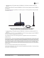
Figure 9. Direct Mounting of Cell Antenna; Cabled WiFi Antenna
Minimum 8-inch (20.32 cm) Separation Between Cell and WiFi
2. Cabled mounting of LTE paddle antennas (GE MDS PN: 97-2485A04) on the Main and AUX Cell
channels.
Cabled mounting of the Wi-Fi antenna (GE MDS PN: 97-4278A34) using a magnetic mount (GE MDS PN:
97-4278A78) or direct mounting of the Wi-Fi to the unit.
This configuration works well for indoor applications in equipment closets for more permanent use.
Outdoor use case:
External enclosures—If the system is going to be installed in a weather-tight enclosure and mounted outside
in the elements, cabled use of external LTE antennas (GE MDS PN: 97-2485A05) on the Main and AUX
Cell channels with cabled use of the External Wi-Fi antenna (GE MDS PN: 97-4278A48) is a good solution.
This configuration requires a suitable metallic ground plane for the Cellular antennas (8" diameter disc minimum for the 97-2485A05 series) or a suitable counterpoise for frequencies as low as 698 MHz. Metal
enclosures work well for ground plane requirements when ground contact inside the box is not impeded by
painted surfaces.
Do not use internally mounted antennas inside of metal enclosures.
Other antenna configurations can be easily customized for applications not listed here. Consult your factory
representative for installation matters.
MDS 05-6628A01, Rev. A
MDS Orbit MCR-4G Technical Manual
11
2.4.5 Accessories and Spares
Table 6 lists common accessories and spare items for use with the MCR-4G. GE MDS also offers an Accessories Selection Guide listing an array of additional items that may be used with the product. Contact your
factory representative or visit www.gemds.com to obtain a copy of the guide.
Table 6. Accessories & Ancillary Items
12
Item
Description
Part Number
DC Power Plug, 2-pin, polarized
Mates with power connector on the
unit’s case. Screw terminals are
provided for wires, threaded locking
screws to prevent accidental
disconnect.
73-1194A53
Setup Guide
(for installation instructions)
Describes the installation and setup
of the unit. It is a companion to this
Technical Manual.
05-6702A01
Flat Mounting Bracket Kit
Brackets that attach to the bottom of
the unit. Used for mounting to a flat
mounting surface.
03-4123A14
COM Port Adapter
Converts the unit’s RJ-45 serial jack
to a DB-9F type.
73-2434A12
MDS Orbit MCR-4G Technical Manual
MDS 05-6628A01, Rev. A
3.0
DEVICE MANAGEMENT
The MCR-4G offers several interfaces to allow device configuration and monitoring of status and performance. These include local serial console, USB, NETCONF, HTTPS, and Secure Shell (SSH) for local and
remote access via the WAN and LAN networks. The serial console and SSH services offer a command line
interface (CLI). There are three user accounts/roles for management access: admin, tech, and oper. User
accounts can be centrally managed with a RADIUS server. RADIUS accounts can be mapped to one of the
three user accounts/roles.
This section describes the steps for connecting a PC, logging in, and setting unit parameters. The focus is
on the local serial console interface, but other methods are similar. The key differences are with initial
access and appearance of data.
3.1 Connecting a PC
3.1.1 Differences Between Serial & SSH
Serial and SSH both present identical management capabilities, but the method of access is different for each. Serial involves an RS-232 serial connection from a PC to the unit’s management
COM port. SSH uses an Ethernet PC connection to the radio’s ETH port. Maximum recommended
cable length for a serial connection is 50 feet (15 meters). SSH can be connected to the radio from
any network point that has connectivity with the PC, including remotely over the Internet, or using
other networks.
The focus of these instructions is on Serial access, but SSH may also be used by following these
additional points, which replace Steps 1-3 below:
• Connect to the unit with a PC that is on the same IP network as the MCR. Launch an SSH
client/server program, and connect to the unit using its programmed IP address.
• The default IP address for the unit is 192.168.1.1. If you do not know the current IP address
of the unit, follow the serial configuration instructions below, where you can determine the
address and continue configuration.
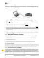
3.1.2 Establishing Communication—Serial Interface
Follow these steps to configure the unit for its first use with serial console interface:
1. Connect a PC to the unit’s COM port as shown in Figure 10. (Maximum recommended cable
length: 50 ft./15 m)
NOTE:
Not all PCs include a serial port. If one is not available, a USB port may be used, along with a USB-to-Serial
adapter (with appropriate driver software). Adapters are available from many manufacturers, including GE
MDS.
NOTE:
If the COM port has been configured for terminal server operation, pressing +++ switches it to console
(management) mode. Serial console mode is required for the following steps.
Launch a terminal communications program, such as HyperTerminal with the following communication parameters: 115200 bps (default speed), 8 bits, no parity, one stop bit (8N1), and flow
control disabled. Incorrect parameter settings are a frequent cause of connection difficulties;
Double check to be sure they are correct.
MDS 05-6628A01, Rev. A
MDS Orbit MCR-4G Technical Manual
13
If necessary, an adapter may be used to convert the unit’s RJ-45 serial jack to a DB-9F type (GE
MDS part no. 73-2434A12). If no serial port exist on the PC, a USB-to-serial adapter cable may
also be used to connect to the MCR unit.
Invisible place holder
PC Running Terminal Session
To COM Port
Figure 10. PC Connection for Programming/Management
2. Press the ENTER key at half-second intervals to receive the Login: prompt. This indicates that the
unit is ready to receive commands.
3. At the Login: prompt, enter admin (lower case) and press
ENTER
.
4. If no password has been previously set, enter the default password (admin) and press ENTER ;
Otherwise, enter the saved password at the Password: prompt. (Before placing the unit in final
service, it is recommended that the default password be changed to ensure that only authorized
users have access.)
5. After successful login, the command prompt appears where you may configure and manage a
number of unit settings.
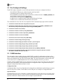
3.1.3 Setting Basic Parameters—First Steps
There are three tasks that should be performed after initial startup and connection to a PC, as follows:
1. Create One-Time Programmable passwords for device recovery in the event a password is lost.
2. Change the login passwords.
3. Evaluate the default factory configuration and lock it down to user's required security level.
Tab Completion Feature
Tab-completion is a powerful feature that presents CLI users with assistance while typing. Depending on
the text that was already entered, tab-completion will display different possible completions. When the tab
key is pressed and no text has been entered, the CLI shows all possible commands that can be typed.
3.1.4 One-Time “Recovery” Passwords
The MDS Orbit platform employs extensive security measures to prevent unauthorized access. As such,
there are no hidden manufacturer passwords or other “backdoors” found in less secure products. If a password is lost, there is no way to access the unit, except by using a one-time password (OTP) for recovery.
This must be established by the user beforehand. Without a one-time password, the unit will not be accessible, and the hardware will need to be replaced. Not even the factory will be able to assist you if a password
is lost, so creating a one-time password is strongly encouraged.
14
MDS Orbit MCR-4G Technical Manual
MDS 05-6628A01, Rev. A
One-Time Passwords: How They Work
One-time recovery passwords put control directly and exclusively in the user’s hands. They are similar to
spare keys for a lock. If you make a spare key, and put it away safely, you can take it out to quickly gain
entry when your primary key is lost. If you don’t make a spare, you are always at risk of locking yourself out.
A one-time recovery password is different from the one used to log into the unit on a routine basis. It is only
for use when the primary password is lost or forgotten. When a one-time password is used to log in, that
password is automatically revoked from the list of passwords created. (You may create up to five one-time
passwords at one time, and more can be created if some get used). A password cannot be used again for
log-in to the unit (hence the name one-time-password).
Creating a One-Time Password
To create a one-time recovery password, proceed as follows:
1. Upon successful log-in, enter the following command:
request system recovery one-time-passwords create function <selected function>
A one-time password is automatically generated and displayed on the screen. Copy this password and
save it in the desired location on your PC. There is no way to ever view it again from the command
line console, so be sure it is properly saved.
2. To create additional one-time passwords (up to a total of five), repeat the step above.
Logging in With a One-Time Password
To use the one-time password for log-in, proceed as follows:
1. At the username prompt, enter the word recovery.
2. At the password prompt, paste in the one-time-password saved earlier on your PC. Using a
one-time-password forces the unit to perform the “function” which was previously defined when the
password was created:
• factory-reset—The unit resets its entire configuration to factory defaults
• login—The unit allows logging in with “admin” privileges
Special case: If someone has disabled console access on the COM port, the login prompt will still be present
on that console, but only one-time-passwords will be accepted. This is done to provide a way to recover the
unit in the case where the COM port has been disabled and the unit cannot be accessed via TCP.
Deleting a One-Time Password
As noted earlier, a one-time password is automatically revoked when it is used for log-in. A revoked password may be replaced, but it must first be removed from the list so a new one can be generated. Any of the
five stored passwords may be removed on demand. As long as there is a free slot, an additional password
can be created, up to the maximum number of five. Logs are generated when the user creates, deletes or logs
in with a one-time-password. To remove an existing password from the list, proceed as follows:
Enter the command request system recovery one-time-passwords delete identifier X, where X is a number 1
through 5.
The current list of passwords may be viewed by issuing the command show system recovery one-time-passwords. The following is an example output from that command. On the unit shown, only two passwords
have been stored. Password 1 or 2 can be deleted from this list.
DATE
IDENTIFIER FUNCTION STATUS
DATE CREATED
REVOKED USER
---------------------------------------------------------------------1
login
useable 2012-06-19T00:27:24+00:00
2
login
useable 2012-06-19T00:27:25+00:00
MDS 05-6628A01, Rev. A
MDS Orbit MCR-4G Technical Manual
15
3.2 Pre-Configured Settings
The MCR is highly configurable to meet field requirements, but comes pre-configured as follows:
• The COM and USB ports are enabled for local console operation
• The Ethernet ports are bridged with the WiFi AP
• WiFi AP SSID is set based on the unit's serial number, and takes the form of: GEMDS_SERNUM> (the
serial number is printed on the chassis sticker)
• WiFi is enabled with passphrase: GEMDS_ORBIT
• A DHCP server is enabled for WiFi clients and the Ethernet LAN ports
• Cellular service is enabled with firewall/router rules in place.
The commands below show how this is accomplished. Each command string begins with the word set:
1. set interfaces interface Wi-Fi wifi-config mode access-point
2. set interfaces interface Wi-Fi wifi-config mode access-point ap-config ap GEMDS_<SERNUM> broadcast-ssid true privacy-mode wpa2-personal psk-config psk GEMDS_ORBIT
3. set interfaces interface Cell ipv4 dhcp
4. set interfaces interface Cell filter input IN_UNTRUSTED
5. set interfaces interface Cell filter output OUT_UNTRUSTED
6. set interfaces interface Cell nat source MASQ
7. set services serial console serial-ports [COM1 USB1]
8. set interfaces interface Bridge virtual-type bridge
9. set interfaces interface Bridge ipv4 address 192.168.1.1 prefix-length 24
10. set interfaces interface Bridge bridge-settings members port LAN1
11. set interfaces interface Bridge bridge-settings members port LAN2
12. set interfaces interface Bridge bridge-settings members wifi-ap GEMDS_<SERNUM>
13. set services dhcp v4subnet 192.168.1.0/24 range-start 192.168.1.2 range-end 192.168.1.10 broad
cast-address 192.168.1.255 router 192.168.1.1
3.3 YANG Interface
The unit employs a data modeling language called YANG to model the configuration and status of the
device. YANG is used in conjunction with the NETCONF protocol to provide a device-specific data model
that can be administered by any NETCONF-capable NMS. The YANG data model is released with each
version of the device so NMS administrators can accurately administer the device per release.
Together, YANG and NETCONF present a structured user interface for the unit. The device data defined
by the YANG data model is either Operational Data or Configuration Data. Configuration Data may be
changed, but Operational Data can only be viewed.
Configuration Data
Configuration Data is any piece of data that can be changed by an administrator and the changes are persistent even if the device reboots. The IP address of the LAN port is an example of Configuration Data.
Operational Data
Operational Data is any piece of data that is volatile and will not be saved if the device is rebooted. Operational data is typically read-only, such as statistics information showing status or a value representing the
operation of the device. Ethernet statistics are an example of operational data.
16
MDS Orbit MCR-4G Technical Manual
MDS 05-6628A01, Rev. A
Default Values
While configuring the unit, some of the configuration data may not need to be explicitly set, but instead the
data assumes the default value defined in the data model. For example, when a File Server configuration is
added and the server type is specified as TFTP, then the remote TFTP port will default to 69 if the user does
not explicitly specify the port. Data nodes that do not have a default value will require the user to input a
value for that node during configuration. The command line interface (CLI) prompts the user to enter a value
for a node if the node is mandatory and does not have a default value.
When the user views the configuration, the nodes that have default values and have not been explicitly set
by the user are not displayed. Users can selectively view these defaulted values by using details option on
the CLI. The show command can be used to view configuration data. Notice the information displayed is
different, depending on which mode the CLI is in; Operational or Configuartion.
Remote Procedure Call (Request)
This is an action that a user requests the device to perform. Rebooting the device, for example, is an action
that is modeled as a request.
Privilege
A user who logs on to the device will belong to a role-based group. Each group is limited in capability to
view operational data or to change configuration data. Less-privileged groups will not be presented with the
option of viewing or changing data on the CLI which can be done by higher-privileged groups.
Changing Configuration Data and committing changes
Changing configuration data requires two steps. The first step is to use a user-interface to add, remove, or
alter a piece of configuration data. The second step is to use the user-interface to commit the change. Multiple changes can be made prior to committing them. This two-step process allows users to make multiple
changes to the configuration and apply them in a bulk commit. Additionally, the device can validate the bulk
commit and reject it if there is an error.
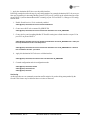
3.3.1 CLI Login Prompt
The CLI is available via the serial console or an SSH session. Use the default serial console settings shown
in the SERIAL CONSOLE section to connect a Computer to the unit via a serial cable. Once the network
settings are configured, users can also connect to the device via SSH over the network.
The CLI prompts for a login to the device before any other actions can be made. The default username is
admin and the default password is admin. These credentials should be changed prior to placing the unit in
full service.
(none) login: admin
Password: (valid password)
Welcome to the CLI
admin connected from 127.0.0.1 using console on (none)
admin@(none) 04:24:12>
Using the CLI
This section will describe how to use the CLI by using an example: changing the name of the unit.
Step 1: Login to the device using the serial console and use the default username “admin” and the default
password admin.
(none) login: admin
Password:
Welcome to the CLI
admin connected from 127.0.0.1 using console on (none)
admin@(none) 04:24:12>
MDS 05-6628A01, Rev. A
MDS Orbit MCR-4G Technical Manual
17
Step 2: Instruct the device to enter configuration mode by typing “configure” and pressing the enter key:
admin@(none) 04:51:06> configure
Entering configuration mode private
[ok][2012-06-20 04:51:07]
[edit]
admin@(none) 04:51:07%
Step 3: Change the device name by typing in the following, followed by enter: set system name Device539
admin@(none) 05:31:14% set system name Device539
[ok][2012-06-20 05:32:45]
[edit]
admin@(none) 05:32:45%
Step 4: Verify the change looks correct by reading the data back using the following, followed by the enter
key: show system name
admin@(none) 05:32:53% show system name
name Device539
[ok][2012-06-20 05:35:28]
[edit]
admin@(none) 05:35:28%
Step 5: Commit the change by typing in the following, followed by the enter key: commit
admin@(none) 05:36:20% commit
Commit complete.
[ok][2012-06-20 05:36:21]
[edit]
admin@(none) 05:36:21%
Step 6: Exit the configuration mode by typing the following, followed by the enter key: exit
admin@(none) 05:40:15% exit
[ok][2012-06-20 05:40:17]
admin@(none) 05:40:17>
Step 7: Exit the login session by typing the following, followed by the enter key: exit
admin@(none) 05:40:32> exit
(none) login:
18
MDS Orbit MCR-4G Technical Manual
MDS 05-6628A01, Rev. A
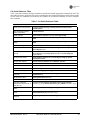
CLI Quick Reference Table
Table 7 provides a summary listing of commonly-needed tasks and the appropriate commands to enter. The
table can be used as a quick reference before consulting the more detailed information which follows in this
section. Each CLI command is proceeded by the symbol > for operational command, or % for a configuration command.
Table 7. CLI Quick Reference Table
If you wish to...
Enter this CLI command:
Create a one-time password
>request system recovery one-time-password create function
<userfunction>
View all network interface
status and statistics
>show interfaces
Create a bridge
%set interfaces interface myBridge virtual-type bridge
Add an interface to a bridge
%set interfaces interface myBridge bridge-settings members port
ETH1
Remove an interface from a
bridge
%delete interfaces interface myBridge bridge-settings members port
ETH1
View WiFi settings
>show configuration interfaces interface Wi-Fi wifi-config | details
Set WiFi AP SSID
%set interfaces interface Wi-Fi wifi-config mode access-point
ap-config ap myssid
Enable WiFi WPA2-Personal
security
%set interfaces interface Wi-Fi wifi-config mode access-point
ap-config ap myssid privacy-mode wpa2-personal psk-config psk
mypassphrase
Configure WiFi details
%set interfaces interface Wi-Fi wifi-config ap-config ap myssid
broadcast-ssid true
Monitor WiFi statistics
>show interfaces interface Wi-Fi statistics | repeat 5
View the cell module status
>show interfaces interface Cell
View the cell APN
>show configuration interfaces interface Cell cell-config apn
View the routing table
>show routing
View the event log
>show table logging event-log | nomore
Set the admin user’s
password
>request system authentication change-password user admin
password admin
Set the device name
%set system name “Mydevice”
Set the baud rate on COM1
%set services serial ports COM1 baud-rateb19200
Download a firmware
package from TFTP server at
192.168.1.10
>request system firmware reprogram-inactive-image filename
iwc-bkrc-1_0_0.mpk manual-file-server { tftp { address 192.168.1.10 } }
Monitor firmware download
status
>show system firmware reprogramming-status
Export configuration file to a
server
>request system configuration-files export filename myConfig.txt
manual-file-server {tftp {192.168.1.10 } }
Reboot device to firmware
image #2
>request system power restart-to-image location 2
MDS 05-6628A01, Rev. A
MDS Orbit MCR-4G Technical Manual
19
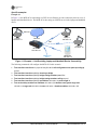
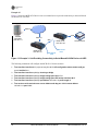
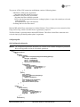
Specific examples
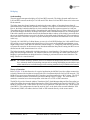
Example #1
In Figure 11, the MCR-4G is functioning as a WiFi Access Point to provide connectivity between a set of
laptops and a handheld device. The MCR-4G is also acting as a DHCP server for the laptops and handheld
device.
Invisible place holder
Ethernet
Laptop 1
192.168.1.11
Laptop 2
192.168.1.12
Ethernet
WiFi
Laptop 3
192.168.1.13
MCR-4G
192.168.1.21
WiFi Access
Point
Handheld 1
192.168.1.14
Figure 11. Example 1: Unit Providing Laptop and Handheld Device Connectivity
The following commands will configure the MCR-4G for this scenario.
1. %set interfaces interface Wi‐Fi physical‐interface Wi‐Fi wifi‐config mode access‐point ap‐config ap myssid
2. %set interfaces interface myBridge virtual‐type bridge
3. %set interfaces interface myBridge bridge‐settings members port ETH1
4. %set interfaces interface myBridge bridge‐settings members wifi‐ap myssid
5. %set interfaces interface myBridge ipv4 address 192.168.1.21 prefix‐length 24
6. %set services dhcp enabled true v4subnet 192.168.1.0/24 domain‐name gemds range‐start 192.168.1.10 range‐end 192.168.1.19 router 192.168.1.1 broadcast‐address 192.168.1.255
20
MDS Orbit MCR-4G Technical Manual
MDS 05-6628A01, Rev. A
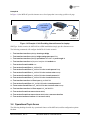
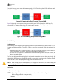
Example #2
In Figure 12, there are two MCR-4G devices, one acting as a WiFi Access Point, the other as a WiFi Station.
Together, the MCR-4G devices are providing a wireless bridge between the laptop and the SCADA device.
Invisible place holder
Ethernet
Laptop 1
192.168.1.11
Ethernet
WiFi
Ethernet
MCR-4G #2
192.168.1.22
MCR-4G #1
192.168.1.21
WiFi Access
Point
SCADA Device
192.168.1.31
WiFi Station
Figure 12. Example 2: Units Providing Wireless Bridge Between Laptop & SCADA Device
The following commands will configure the MCR-4G #1 for this scenario.
1. %set interfaces interface Wi‐Fi physical‐interface Wi‐Fi wifi‐config mode access‐point ap‐config ap myssid
2. %set interfaces interface myBridge virtual‐type bridge 3. %set interfaces interface myBridge bridge‐settings members port ETH1
4. %set interfaces interface myBridge bridge‐settings members wifi‐ap myssid
5. %set interfaces interface myBridge ipv4 address 192.168.1.21 prefix‐length 24
6. %set services enabled true dhcp v4subnet 192.168.1.0/24 domain‐name gemds range‐start 192.168.1.10 range‐end 192.168.1.19 router 192.168.1.1 broadcast‐address 192.168.1.255
The following commands will configure the MCR-4G #2 for this scenario.
1. %set interfaces interface Wi‐Fi physical‐interface Wi‐Fi wifi‐config mode station station‐config ap myssid enabled true
2. %set interfaces interface myBridge virtual‐type bridge 3. %set interfaces interface myBridge bridge‐settings ports port ETH1
4. %set interfaces interface myBridge bridge‐settings ports wifi‐station interface Wi‐Fi
5. %set interfaces interface myBridge ipv4 address 192.168.1.22 prefix‐length 24
MDS 05-6628A01, Rev. A
MDS Orbit MCR-4G Technical Manual
21
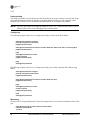
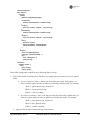
Example #3
Figure 13 shows the MCR-4G #2 device acts as a terminal server to provide connectivity to the serial-based
SCADA device via UDP.
Invisible place holder
Ethernet
SCADA
application
192.168.1.11
serial
Ethernet
WiFi
MCR-4G #2
192.168.1.22
MCR-4G #1
192.168.1.21
WiFi Access
Point
SCADA Device
WiFi Access
Point
Figure 13. Example 3: Unit Providing Connectivity to Serial-Based SCADA Device via UDP
The following commands will configure the MCR-4G #2 for this scenario.
1. %set interfaces interface Wi‐Fi physical‐interface Wi‐Fi wifi‐config mode station station‐config ap myssid enabled true
2. %set interfaces interface myBridge virtual‐type bridge 3. %set interfaces interface myBridge bridge‐settings ports port ETH1
4. %set interfaces interface myBridge bridge‐settings ports wifi‐station interface Wi‐Fi
5. %set interfaces interface myBridge ipv4 address 192.168.1.22 prefix‐length 24
6. %set services serial terminal‐server server COM1 mode udp port 30000 remote address 192.168.1.11 port 30001
22
MDS Orbit MCR-4G Technical Manual
MDS 05-6628A01, Rev. A
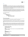
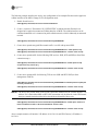
Example #4
In Figure 14, the MCR-4G provides internet access for a laptop that is accessing a public web page.
Invisible place holder
Ethernet
Public Carrier
Network
Internet
MCR-4G
192.168.1.21
Internet web
server
Cellular
Laptop 1
192.168.1.11
Figure 14. Example 4: Unit Providing Internet Access for Laptop
SIM Type: In this scenario, the MCR-4G has a SIM installed that simply provides Internet access.
The following commands will configure the MCR-4G for this scenario.
1. %set interfaces interface myBridge virtual‐type bridge 2. %set interfaces interface myBridge bridge‐settings ports port ETH1
3. %set interfaces interface myBridge ipv4 address 192.168.1.21 prefix‐length 24
4. %set interfaces interface Cell physical‐interface Cell enabled true
5. %set services firewall enabled true
6. %set services firewall filter IN_UNTRUSTED
7. %set services firewall filter IN_UNTRUSTED rule 1 match protocol icmp
8. %set services firewall filter IN_UNTRUSTED rule 1 actions action accept
9. %set services firewall filter IN_UNTRUSTED rule 10 match protocol all
10. %set services firewall filter IN_UNTRUSTED rule 10 actions action drop
11. %set interfaces interface Cell filter input IN_UNTRUSTED
12. %set services firewall filter OUT_UNTRUSTED rule 10 match protocol all
13. %vset services firewall filter OUT_UNTRUSTED rule 10 actions action accept
14. %set interfaces interface Cell filter output OUT_UNTRUSTED
15. %set services firewall nat source rule‐set MASQ
16. %set services firewall nat source rule‐set MASQ rule 1 source‐nat interface
17. %set services interfaces interface Cell nat source MASQ
3.4 Operational Topic Areas
The following headings describe key operational features of the MCR unit, and list configuration options
for them.
MDS 05-6628A01, Rev. A
MDS Orbit MCR-4G Technical Manual
23
Serial Console
A serial cable may be used to connected to a COM port on the unit to access the CLI. The default serial
console settings are 115200 bps with 8N1 format. A mini-USB-to-USB cable may also be used to connect
to a Computer in case no serial port exists. If a mini-USB connection is used, the computer must contain
the appropriate device driver. A driver for serial operation can be found on GE MDS website.
Configuring
This sequence shows how to add console access to the COM serial port and set the baud rate to 19200 bps:
admin@(none) 00:04:43% set services serial console serial-ports [ COM1 COM2 ]
[ok][2012-06-19 00:04:57]
[edit]
admin@(none) 00:04:59% set services serial ports COM2 baud-rate b19200
[ok][2012-06-19 00:05:28]
[edit]
admin@(none) 00:05:28% commit
Commit complete.
[ok][2012-06-19 00:07:51]
[edit]
admin@(none) 00:07:51%
Monitoring
Ensure the CLI is in operational mode. Follow the example below to view the state and statistics:
admin@(none) 00:10:38> show configuration services serial | details
ports COM1 {
line-mode
rs232;
duplex-mode full;
baud-rate b115200;
byte-format bf8n1;
hw-flow-control false;
vmin
255;
vtime
1;
capability
3;
}
ports COM2 {
line-mode
rs232;
duplex-mode full;
baud-rate
b19200;
byte-format bf8n1;
hw-flow-control false;
vmin
255;
vtime
1;
capability
0;
}
console {
serial-ports [ COM1 COM2 ];
}
[ok][2012-06-19 00:12:00]
admin@(none) 00:12:00>
24
MDS Orbit MCR-4G Technical Manual
MDS 05-6628A01, Rev. A
Network
Understanding
The unit has multiple network interfaces including LAN, Cellular, and WiFi. Each of these has numerous
networking features and each feature is described below in a separate section:
•
•
•
•
•
Static or dynamic IP addressing (DHCP) for each interface
Bridging
Firewall
Routing
VPN
Configuring
See each individual section for details about configuring the LAN, Cell, WiFi interfaces, and related networking features.
Monitoring
Ensure the CLI is in operational mode. Follow the example below to view the state and statistics of all the
network interfaces:
admin@(none) 03:38:19> show interfaces
MDS 05-6628A01, Rev. A
MDS Orbit MCR-4G Technical Manual
25
LAN
Understanding
The unit has external Local Area Network (LAN) ports that can be used to connect to a local LAN. It supports both IPv4 and IPv6 addresses and may be assigned multiple IP addresses. The LAN port can be
assigned static IP addresses or a dynamically allocated address can be assigned using DHCP.
NOTE: The LAN port should be assigned IP addresses only if it is a routed interface (that is, not in a
bridge). Refer to the section on Bridging later in the document.
Configuring
The following sequence shows how to configure the LAN1 port with a static IPv4 address:
admin@(none) 06:03:53> configure
Entering configuration mode private
[ok][2012-06-20 06:03:54]
admin@(none) 06:04:45% set interfaces interface ETH1 ipv4 address 192.168.1.11 prefix-length 24
[ok][2012-06-20 06:05:01]
[edit]
admin@(none) 06:05:01% commit
Commit complete.
[ok][2012-06-20 06:05:03]
[edit]
admin@(none) 06:05:03%
The following sequence shows how to configure the LAN1 port to obtain a dynamic IPv4 address using
DHCP:
admin@(none) 06:03:53> configure
Entering configuration mode private
[ok][2012-06-20 06:03:54]
admin@(none) 06:04:45% set interfaces interface ETH1 ipv4 dhcp
[ok][2012-06-20 06:05:01]
[edit]
admin@(none) 06:05:01% commit
Commit complete.
[ok][2012-06-20 06:05:03]
[edit]
admin@(none) 06:05:03%
Monitoring
Ensure the CLI is in Operational mode. Follow the example below to view the state and statistics of the LAN
port:
admin@(none) 03:38:19> show interfaces interface ETH1
interfaces interface ETH1
if-index 2
26
MDS Orbit MCR-4G Technical Manual
MDS 05-6628A01, Rev. A
status mac-address 00:00:00:00:01:01
status mtu 1500
status link up
status ipv4 address [ 192.168.1.10/24 192.168.1.11/24 ]
status ipv6 address [ fe80::200:ff:fe00:101/64 ]
status counters collisions 0
status counters multicast 0
status counters rx_bytes 2022760
status counters rx_compressed 0
status counters rx_crc_errors 0
status counters rx_dropped 0
status counters rx_errors 0
status counters rx_fifo_errors 0
status counters rx_frame_errors 0
status counters rx_length_errors 0
status counters rx_missed_errors 0
status counters rx_packets 8859
status counters rx_over_errors 0
status counters tx_aborted_errors 0
status counters tx_bytes 21371
status counters tx_carrier_errors 0
status counters tx_compressed 0
status counters tx_dropped 0
status counters tx_errors 0
status counters tx_fifo_errors 0
status counters tx_heartbeat_errors 0
status counters tx_packets 232
status counters tx_window_errors 0
[ok][2012-06-21 03:38:24]
admin@(none) 03:38:24>
MDS 05-6628A01, Rev. A
MDS Orbit MCR-4G Technical Manual
27
VLAN Operation
Understanding
Virtual Local Area Networks (VLANs) are generic interface types in the MCR-4G, and can be assigned
unique IP addresses. They are treated the same as any other interface type, but they offer a way to link traffic
between interface ports. As such, a VLAN device can be thought of as a “bridging device.”
Setup
To setup a VLAN, you must first create one or more VLAN interfaces. Two sample commands are shown
below for doing this; one with an ID of 99 and another with an ID of 300:
set interfaces interface mgmt_vlan virtual-type vlan vlan-config vlan-id 99
set interfaces interface video_vlan virtual-type vlan vlan-config vlan-id 300
Operational Modes
VLAN interfaces can have three separate modes: none (default), trunk, or access. These modes are used to
set interface behavior, and examples of their use are provided below.
Trunk: To add ETH1 as a trunk (tagged) port in both defined VLANs above, the command is:
set interfaces interface ETH1 vlan-mode trunk vlans [ video_vlan mgmt_vlan ]
By issuing these commands, two bridges are created internally, which are background operations, hidden
from the user. (In this case, the two bridges are br_vlan99 and br_vlan300).
When an interface is specified as a trunk member of the VLAN, the system creates a Linux VLAN interface
(eth0.99 & eth0.300) which strips off VLAN tags on ingress, and applies them on egress. This new device is
then added as a member of the br_vlan99 & br_vlan300 bridges.
Access: To set ETH2 as an access port for video_vlan the command is:
set interfaces interface ETH2 vlan-mode access vlan video_vlan
This command adds the ETH2 interface as a member of the br_vlan300 bridge, although it is not outwardly
apparent to the user.
Native VLANs
A VLAN device may also be specified as a “native” VLAN, and this is set by the command:
set interfaces interface my_native_vlan virtual-type vlan vlan-config vlan-id 600 native-vlan true
As in the earlier examples, native VLANs are nothing more than a bridge, but they cannot have trunk ports.
It should also be understood that bridges cannot contain other bridges. For this reason, it is not possible to
assign a bridge interface to a VLAN. Also, VLANs serve as interfaces, so you can assign IP addresses to
them and treat them the same as any other interface type.
28
MDS Orbit MCR-4G Technical Manual
MDS 05-6628A01, Rev. A
Cell
Understanding
The unit incorporates a 4G LTE module capable of operation on Verizon Wireless LTE/CDMA network
(LTE 700Mhz Band 13) in the United States. The unit supports routing of TCP/UDP/IP data from the Cellular WAN network interface to any of the other network interfaces (including WiFi or LAN) using the
IPsec VPN or network address and port translation (NAPT) feature and to the COM1 (or COM2) serial port
using the terminal server service. The configuration of these uses cases is specified in respective sections
on VPN, Firewall and NAT, and Terminal Service.
The cellular modem inside the unit supports main (primary) and secondary antenna (for receive diversity).
The primary antenna must be installed for cell modem to register with the cellular network. It is strongly
recommended that secondary antenna be installed for achieving a robust cellular link. There should be no
physical obstructions around the antennas. The main and diversity antennas must have a minimum amount
of 27 dB isolation from each other to ensure optimal LTE mode operation of the module.
Cell Configuration Hierarchy
interface cell {
cell-config {
apn <apn-name>
lte-recovery <true|false>
keep-alive {
address <host name or address>
interval <host name or address>
}
}
}
Access Point Name (APN)
After MCR has registered on the cellular network, it sets up the IP data connection with a specific Packet
Data Network identified by the Access Point Name (APN). APN is a string identifier.
The MCR comes preconfigured with APN of “vzwinternet”. Hence, it attempts to set up a data connection
toward internet PDN that provides internet connectivity. For this data connection to succeed, a SIM card
that has been provisioned for internet access needs to be obtained from the service provider and installed in
MCR.
If a private network (PN) account has been arranged with the service provider, a SIM card will be issued
from that account. When the modem is powered up with such a SIM, the default APN on the modem is automatically updated by the service provider to the one that identifies the user’s private network. This procedure is called OTA APN update. This procedure may not always succeed, and hence, requires the user to
manually update the APN on the MCR. The following example shows how to update APN manually via
CLI:
admin@(none) 15:28:44> config
Entering configuration mode private
[ok][2013-01-18 15:28:46]
[edit]
admin@(none) 15:28:46% set interfaces interface cell cell-config apn GEDEROC.GW6.VZWENTP
[ok][2013-01-18 15:29:36]
[edit]
admin@(none) 15:29:36% commit
Commit complete.
[ok][2013-01-18 15:29:46]
[edit]
admin@(none) 15:29:46% exit
MDS 05-6628A01, Rev. A
MDS Orbit MCR-4G Technical Manual
29
LTE Recovery
The cellular modem used inside the unit may occasionally remain in a 3G (EVDO-REV A) service state and
not transition to 4G LTE. The firmware incorporates a recovery mechanism to recover from this condition.
If the cellular modem has been in 3G coverage for more than 15 minutes, the firmware resets the modem to
bring it back into LTE service state. LTE recovery is enabled by default. This mechanism should be disabled
if the unit is deployed in areas that either lack or have poor LTE coverage. Otherwise, the cellular modem
will unnecessarily reset every 15 minutes.
This feature allows the cellular modem to maintain a connection in situations where no traffic is passed over
cellular link for long periods of time, which would otherwise cause disruption. The keep alive mechanism
sends an ICMP echo message to the configured address/host at the configured interval. This feature should
be used only if an application is passing data very infrequently over a cellular connection (i.e., if data is
passed at a rate of less than once per hour).
The commands for setting 3G/4G operation are as follows:
4G Operation – Default programming.
% set interfaces interface Cell cell-config service-recovery lte-recovery true
% commit
3G Operation – Turn off the LTE Recovery Mode to allow continual 3G mode operation without periodic
disconnection for 4G service search.
% set interfaces interface Cell cell-config service-recovery lte-recovery false
% commitKeep Alive
NOTE: The Verizon network can disconnect the cellular connection if any packets get routed from LAN
to Cellular interface without undergoing masquerading (Source Network Address Translation
(NAT) before exiting the cellular interface. Therefore, always configure masquerading on the
cellular interface. Refer to the “Firewall and NAT” section in this manual for more information
on NAT configuration.
Monitoring
Ensure the CLI is in Operational mode. Follow the example below to view the cellular interface state and
statistics:
admin@(none) 16:23:34> show interfaces interface cell
interfaces interface eth1
if-index 6
status mac-address 00:a0:c6:00:00:00
status mtu 1500
status link up
status ipv4 address [ 172.18.175.131/29 ]
status ipv6 address [ fe80::2a0:c6ff:fe00:0/64 ]
status counters collisions 0
status counters multicast 0
status counters rx_bytes 50574
status counters rx_compressed 0
status counters rx_crc_errors 0
status counters rx_dropped 0
status counters rx_errors 0
status counters rx_fifo_errors 0
status counters rx_frame_errors 0
status counters rx_length_errors 0
30
MDS Orbit MCR-4G Technical Manual
MDS 05-6628A01, Rev. A
status counters rx_missed_errors 0
status counters rx_packets 259
status counters rx_over_errors 0
status counters tx_aborted_errors 0
status counters tx_bytes 40114
status counters tx_carrier_errors 0
status counters tx_compressed 0
status counters tx_dropped 0
status counters tx_errors 0
status counters tx_fifo_errors 0
status counters tx_heartbeat_errors 0
status counters tx_packets 273
status counters tx_window_errors 0
cell-status imsi 311480023788535
cell-status imei 990000624071751
cell-status iccid 89148000000234127059
cell-status mdn 5853534418
cell-status apn GEDEROC.GW6.VZWENTP
cell-status sw-version "1.41 SVN 0 [2011-08-23 18:47:59]"
cell-status sim-state "SIM INIT COMPLETED"
cell-status modem-state connected
cell-status roaming-state home
cell-status service-state lte
cell-status rssi -61
[ok][2013-01-18 16:23:38]
Determining the Cell Module’s IMSI/IMEI
When provisioning the cell module for network service, the cellular provider typically requires the International Mobile Subscriber Identity code (IMSI) or International Mobile Station Equipment Identity code
(IMEI) to be provided. These codes can be determined by entering the following command:
show interfaces interface Cell cell-status
(Where Cell is the configured name for the cellular device. Cell is the factory default name, but it may have
been changed by a previous user.)
When the above command is entered, a number of items are returned as shown in the example below. The
first two items (highlighted blue) show the IMSI and IMEI codes. These are unique for each unit.
cell-status imsi 311480023631413
cell-status imei 990000947608727
cell-status iccid 89148000000232694605
cell-status mdn 5857948168
cell-status apn VZWINTERNET
cell-status app-sw-version 0.0.5
cell-status modem-sw-version "4.08.02 SVN 0 [2012-12-21 10:52:58]"
cell-status sim-state Ready
cell-status modem-state connected
cell-status roaming-state home
cell-status service-state lte
cell-status rssi -62
MDS 05-6628A01, Rev. A
MDS Orbit MCR-4G Technical Manual
31
WiFi
Understanding
The internal WiFi module has FCC modular approval and may only be used with one of the GE MDS
approved antennas (see 802.11 WiFi Module Specifications below). The WiFi antenna is connected to the
reverse-SMA connector on the unit’s front panel. Only these antennas may be used. The WiFi module can
be configured to operate as an 802.11b/g/n Access Point or Station. The operational mode and frequency
can be configured through the user interface.
The specifications for the 2.4 GHz WiFi module are as follows:
•
•
•
•
Protocol: IEEE 802.11b/g/n OFDM 6 to 54Mbps, CCK 1 to 11Mbps
Frequency Range: 2400 to 2500 MHz
Maximum Transmit Power: 18 dBm (Default is 15 dBm)
Permissible Antennas:
- GE MDS 97-4278A36
- GE MDS 97-4278A34
- GE MDS 97-4278A35
• FCC: Part 15C
• FCC ID: VRA-SG9011028
• WiFi Antenna Connector: Female Reverse SMA
The unit supports the following WiFi security modes:
1. None (should be used only to test connectivity)
2. WPA2 + CCMP/AES Encryption – This mode should be used if all client devices support WPA2/CCMP.
3. Encryption + TKIP Encryption – This mode should be used if there is mix of both legacy client devices
that only support WPA/TKIP and newer devices that support WPA2/CCMP.
Also, WPA and WPA2 can be configured further in following modes:
• Personal – This uses pre-shared keys (passphrases) configured on the MCR and client devices.
• Enterprise – This supports EAP-TLS based authentication of client devices (configured with certificates/keys) via RADIUS.
The default SSID is based on the unit's serial number, and takes the form of: GEMDS_<SERNUM> (the serial
number is printed on the chassis sticker). The default password for WiFi operation is GEMDS_ORBIT.
AP Mode
Basic configuration with defaults
The following will configure a basic access point with ‘somessid’ and default settings.
admin@(none) 00:17:10% set interfaces interface physical-interface WiFi wlan0 wifi-config mode
access-point ap-config ssid somessid
[ok][2012-06-19 00:17:29]
[edit]
admin@(none) 00:17:29% show interfaces interface wlan0 wifi-config | details
mode access-point;
32
MDS Orbit MCR-4G Technical Manual
MDS 05-6628A01, Rev. A
tx-power 15;
ap-config {
ssid
somessid;
broadcast-ssid true;
channel
6;
station-max 7;
station-timeout 300;
beacon-interval 100;
operation-mode 80211g;
dtim-period 2;
rts-threshold 2347;
fragm-threshold 2346;
privacy-mode none;
}
[ok][2012-06-19 00:17:37]
admin@(none) 00:17:37% commit
Commit complete.
Privacy mode configuration
The default privacy mode, as shown above, is none.
The following configures the unit to use WPA2-Personal security with the default CCMP/AES encryption.
admin@(none) 00:19:02% set interfaces interface wlan0 wifi-config ap-config privacy-mode wpa2-personal psk-config psk somepassphrase
[ok][2012-06-19 00:26:51]
[edit]
admin@(none) 00:26:51% show interfaces interface wi-fi wifi-config | details
mode access-point;
tx-power 15;
ap-config {
ssid
somessid;
broadcast-ssid false;
channel
6;
station-max 7;
station-timeout 300;
beacon-interval 100;
operation-mode 80211g;
dtim-period 2;
rts-threshold 2347;
fragm-threshold 2346;
privacy-mode wpa2-personal;
psk-config {
encryption ccmp;
key-mgmt wpa-psk;
psk
somepassphrase;
}
}
[ok][2012-06-19 00:27:01]
[edit]
admin@(none) 00:27:01% commit
Commit complete.
The following configures the unit to use WPA2-Personal security with the CCMP/AES encryption + TKIP
encryption.
MDS 05-6628A01, Rev. A
MDS Orbit MCR-4G Technical Manual
33
admin@(none) 00:19:02% set interfaces interface wlan0 wifi-config ap-config privacy-mode wpa2-personal psk-config encryption ccmp-tkip psk somepassphrase
[ok][2012-06-19 00:26:51]
[edit]
admin@(none) 00:26:51% show interfaces interface wlan0 wifi-config | detail
mode access-point;
tx-power 15;
ap-config {
ssid
somessid;
broadcast-ssid false;
channel
6;
station-max 7;
station-timeout 300;
beacon-interval 100;
operation-mode 80211g;
dtim-period 2;
rts-threshold 2347;
fragm-threshold 2346;
privacy-mode wpa2-personal;
psk-config {
encryption ccmp-tkip;
key-mgmt wpa-psk;
psk
somepassphrase;
}
}
[ok][2012-06-19 00:27:01]
[edit]
admin@(none) 00:27:01% commit
Commit complete.
Other configuration
The following configures the device to broadcast its ssid, support 802.11b/g/n modes, and operate on
channel 3.
admin@(none) 00:27:59% set interfaces interface wlan0 wifi-config ap-config broadcast-ssid true
operation-mode 80211n channel 3
[ok][2012-06-19 00:36:30]
[edit]
admin@(none) 00:36:30% show interfaces interface wlan0 wifi-config | details
mode access-point;
tx-power 15;
ap-config {
ssid
somessid;
broadcast-ssid true;
channel
3;
station-max 7;
station-timeout 300;
beacon-interval 100;
operation-mode 80211n;
dtim-period 2;
rts-threshold 2347;
fragm-threshold 2346;
privacy-mode wpa2-personal;
psk-config {
encryption ccmp;
key-mgmt wpa-psk;
psk
somepassphrase;
34
MDS Orbit MCR-4G Technical Manual
MDS 05-6628A01, Rev. A
}
}
[ok][2012-06-19 00:36:39]
[edit]
admin@(none) 00:36:39% commit
Commit complete.
Station Mode
This command sets the unit to act as WiFi station to connect to an AP with somessid and WPA2 Personal
security.
admin@(none) 00:43:09% set interfaces interface wlan0 wifi-config
station-config ap somessid enabled true privacy-mode wpa2-personal psk-config psk somepassphrase
[ok][2012-06-19 00:43:26]
[edit]
admin@(none) 00:43:26% show interfaces interface wlan0 wifi-config | detail
mode station;
tx-power 15;
station-config {
ap somessid {
priority 1;
enabled
true;
privacy-mode wpa2-personal;
psk-config {
encryption ccmp;
key-mgmt wpa-psk;
psk
somepassphrase;
}
}
}
[ok][2012-06-19 00:43:34]
[edit]
admin@(none) 00:43:34% commit
Commit complete.
Monitoring
Ensure the CLI is in Operational mode.
Access Point Mode
The following shows status with two stations connected. Note that in this case bssinfo-x represents the station statistics/data (i.e., id is the station MAC address).
admin@(none) 01:06:26> show interfaces interface wlan0 wifi-status
wifi-status mode “Access Point”
wifi-status ssid “”
wifi-status privacy “”
wifi-status channel 0
wifi-status tx-power 15
wifi-status bssinfo-0 “id: 98:4b:4a:5a:53:2d, inactive: 330, rx bytes: 1126, rx packets: 11, tx bytes: 355,
tx packets: 3, tx retries: 0, tx failed: 0, tx bitrate: 6, signal: -37, authorized : yes, authenticated : yes”
wifi-status bssinfo-1 “id: f4:ec:38:99:01:e2, inactive: 7770, rx bytes: 529, rx packets: 6, tx bytes: 355, tx
packets: 3, tx retries: 0, tx failed: 0, tx bitrate: 6, signal: -47, authorized : yes, authenticated : yes”
[ok][2012-06-19 01:06:29]
MDS 05-6628A01, Rev. A
MDS Orbit MCR-4G Technical Manual
35
Station Mode
The following shows status when connected to a configured AP. Note that in this case bssinfo-0 represents
the AP (i.e., id is the bssid).
admin@(none) 00:52:24> show interfaces interface wlan0 wifi-status
wifi-status mode Station
wifi-status ssid somessid
wifi-status privacy “”
wifi-status channel 6
wifi-status tx-power 15
wifi-status bssinfo-0 “id: 4c:e6:76:50:85:32, inactive: 89750, rx bytes: 206463, rx packets: 1766, tx
bytes: 1135, tx packets: 13, tx retries: 0, tx failed: 0, tx bitrate: 65, signal: -13, authorized : yes, authenticated : yes”
[ok][2012-06-19 00:52:34]
36
MDS Orbit MCR-4G Technical Manual
MDS 05-6628A01, Rev. A
Bridging
Understanding
The unit supports transparent bridging of LAN and WiFi networks. The bridge forwards traffic between
LAN and WiFi networks at the layer-2 of OSI model. This allows LAN and WiFi clients to be in the same
IP sub-network.
The bridge learns the clients’ locations by analyzing the source address of incoming frames from all
attached networks (LAN and WiFi network). For example, if a bridge sees a frame arrive on LAN port from
Host A, the bridge concludes that Host A can be reached through the segment connected to LAN port.
Through this process, the bridge builds a forwarding table (the learning process). When a frame is received
on one of the bridge's interfaces, the bridge looks up the frame's destination address in its forwarding table.
If the table contains an association between the destination address and any of the bridge's ports aside from
the one on which the frame was received, the frame is forwarded out the indicated port. If no association is
found, the frame is flooded to all ports except the inbound port. Broadcasts and multicasts also are flooded
in this way.
Typically, for LAN/WiFi-to-Cellular Router use case (a.k.a LAN/WiFi HotSpot), the LAN and WiFi interface (acting as an Access Point) are bridged. However, for security and bandwidth considerations, a user
might want to remove LAN and WiFi networks from the bridge (i.e., configuring LAN and WiFi networks
as separate IP networks). In this network setup, broadcast/multicasts data packets coming into WiFi are not
directed out the LAN connection and vice versa.
The bridged network is addressable via bridge interface (a virtual interface). The interfaces that are in the
bridge are called bridged interfaces. The interfaces that are not in the bridge are called routed interfaces.
Bridging is performed between bridged interfaces. Routing is performed between routed interfaces. The
bridge interface is a routed interface.
NOTE: The Cellular modem by its nature can never be added to the bridge and is, therefore, a routed interface. Advanced details of networking concepts such as routing and bridging are outside the scope
of this manual but are available through various training materials freely available on the Internet.
Theory of Operation
Refer to Figure 15 for this discussion. In a typical application, the MCR-4G provides cellular connectivity
to locally connected devices that are located on the user’s local/internal/private LAN or WiFi network. The
MCR-4G acts as an Access Point on the Wi-Fi interface, providing connectivity to Wi-Fi clients. The Wi-Fi
traffic is combined with the local Ethernet port traffic through a Layer 2 bridge. The serial interface is
matched to a terminal server that encapsulates serial data over a TCP or UDP connection.
The MCR-4G provides Network Address Translation (NAT) (both Masquerading and Port Forwarding) as
well as Firewalling between the cellular data interface (WAN side) and the local network (LAN/WiFi). The
MCR-4G can also act as a VPN client to provide a secure tunnel for LAN data to the user’s local network
(LAN/WiFi). This configuration obviates the need for NAT, as the back-office network behind the VPN
Concentrator (VPNC) can address the local LAN or WiFi network directly via the secure tunnel.
MDS 05-6628A01, Rev. A
MDS Orbit MCR-4G Technical Manual
37
Invisible place holder
Figure 15. Bridging Functions Diagram
Configuring
Creating a bridge interface and assigning it an IP address:
admin@(none) 00:02:09% set interfaces interface myBridge type bridge
admin@(none) 00:02:20% set interfaces interface myBridge bridge-settings ageing-time 500
admin@(none) 00:22:26% set interfaces interface myBridge ipv4 address 192.168.1.10 prefix-length 24
Adding LAN interface to the bridge:
admin@(none) 00:06:20% set interfaces interface myBridge bridge-settings members port eth0
Adding WiFi interface to the bridge:
admin@(none) 00:06:20% set interfaces interface myBridge bridge-settings members wifi-ap /
wifi-stationwlan0
Removing LAN interface from the bridge:
admin@(none) 00:06:36% delete interfaces interface myBridge bridge-settings members port eth0
Removing WiFi interface from the bridge:
admin@(none) 00:06:20% delete interfaces interface myBridge bridge-settings members wifi-ap /
wifi-station wlan0
Removing the bridge interface:
admin@(none) 00:23:00% delete interfaces interface myBridge
38
MDS Orbit MCR-4G Technical Manual
MDS 05-6628A01, Rev. A
Monitoring
Ensure the CLI is in operational mode. Follow the example below to view the state and statistics of a bridge.
In this example, bridge br0 is bridging LAN (eth0) and WiFi (wlan0) networks.
interfaces interface br0
if-index 4
status mac-address 00:19:70:94:7e:2d
status mtu 1500
status link up
status ipv4 address [ 10.10.1.1/24 ]
status ipv6 address [ fe80::c4ff:bdff:feaf:b9f6/64 ]
status counters collisions 0
status counters multicast 0
status counters rx_bytes 7094971
status counters rx_compressed 0
status counters rx_crc_errors 0
status counters rx_dropped 0
status counters rx_errors 0
status counters rx_fifo_errors 0
status counters rx_frame_errors 0
status counters rx_length_errors 0
status counters rx_missed_errors 0
status counters rx_packets 151306
status counters rx_over_errors 0
status counters tx_aborted_errors 0
status counters tx_bytes 275063
status counters tx_carrier_errors 0
status counters tx_compressed 0
status counters tx_dropped 0
status counters tx_errors 0
status counters tx_fifo_errors 0
status counters tx_heartbeat_errors 0
status counters tx_packets 3199
status counters tx_window_errors 0
bridgeStatus stp port eth0
number
1
priority
0
state
forwarding
path-cost
19
designated-root 8000.001970947e2d
designated-cost 0
designated-bridge 8000.001970947e2d
designated-port 32769
bridgeStatus stp port wlan0
number
2
priority
0
state
forwarding
path-cost
100
designated-root 8000.001970947e2d
designated-cost 0
designated-bridge 8000.001970947e2d
designated-port 32770
[ok][2013-01-24 14:27:15]
MDS 05-6628A01, Rev. A
MDS Orbit MCR-4G Technical Manual
39
Routing
Understanding
The unit can be configured to route IP packets between routed interfaces.
Configuring a default static route:
admin@(none) 00:50:52% set routing static-routes ipv4 route 1 dest-prefix 0.0.0.0/0 next-hop
192.168.1.10
Configuring a static host route:
set routing static-routes ipv4 route 2 dest-prefix 10.2.3.1/32 next-hop 192.168.1.9
admin@(none) 00:04:57% show routing static-routes
ipv4 {
route 1 {
dest-prefix 0.0.0.0/0;
next-hop 192.168.1.10;
route 2 {
dest-prefix 10.2.3.1/32;
next-hop 192.168.1.9;
[ok][2012-06-19 00:05:01]
[edit]
admin@(none) 00:05:01%
Monitoring
Ensure the CLI is in operational mode. Follow the example below to view the state of the routing table:
admin@(none) 00:05:27> show routing
OUTGOING
SOURCE
V6UR:DEST V6UR:NEXT V4UR:DEST
V4UR:NEXT
INTERFACE PROTOCOL AGE PREFIX
HOP
PREFIX
HOP
------------------------------------------------------------------------eth0
static
0.0.0.0/0
192.168.1.10
eth0
static
10.2.3.1/32
192.168.1.9
eth0
direct
192.168.1.0/24 OUTGOING
SOURCE
V6UR:DEST V6UR:NEXT V4UR:DEST V4UR:NEXT
INTERFACE PROTOCOL AGE PREFIX
HOP
PREFIX
HOP
---------------------------------------------------------------------eth0
direct
fe80::/64 eth1
direct
fe80::/64 [ok][2012-06-19 00:05:29]
40
MDS Orbit MCR-4G Technical Manual
MDS 05-6628A01, Rev. A
Firewall and NAT
Understanding
The MCR incorporates a firewall service that provides the following functionality:
1. Packet filtering to permit or deny incoming or outgoing traffic on an interface.
2. Network Address Translation (NAT)
• Source NAT - Masquerading
• Destination NAT – Port Forwarding
Packet Flow
This section provides a simplified view of packet flow for various categories of traffic flows going in and
out of the MCR unit. Figure 16 shows the flow of packets terminating at MCR. For example, device management traffic using SSH or NETCONF protocol terminating at local device management process within
the MCR unit.
Invisible place holder
Figure 16. Packets Terminating at MCR
Figure 17 shows flow of packets originating from the MCR unit. For example, DNS queries and/or VPN
connection setup traffic originating from local VPN service within the MCR unit.
Invisible place holder
Figure 17. Packets Originating from MCR
Figure 18 shows the flow of packets being forwarded (routed) through the MCR unit. For example, IP
packets arriving inside IPsec VPN tunnel, being routed from cellular WAN to the local Ethernet interface.
Invisible place holder
Figure 18. Packets Being Forwarded Through MCR
MDS 05-6628A01, Rev. A
MDS Orbit MCR-4G Technical Manual
41
Figure 19 shows the flow of packets being port-forwarded (DNAT’ed) through the MCR unit. For example,
TCP traffic arriving at the cellular interface and getting port forwarded to a private host connected to the
local Ethernet interface.
Invisible place holder
Figure 19. Packets Being Port-Forwarded Through MCR
Figure 20 shows the flow of packets being masqueraded (source NATed) through the MCR unit. For
example, TCP traffic from a private host arriving at Local Ethernet interface, being masqueraded to the cellular interface’s IP address before being sent out the cellular interface.
Invisible place holder
Figure 20. Packets Being Masqueraded Through MCR
Packet Filtering
Understanding
Packet filtering allows configuring and applying a packet filter (also called Access Control List, or ACL) to
incoming or outgoing traffic on an interface. A filter is a set of one or more rules. Each rule consists of two
parts:
• Matching criteria that a packet must satisfy for the rule to be applied. Matching criteria consists of
various parameters like protocol, source/destination addresses and ports etc
• Actions that specify what to do with the packet when the matching criteria is met, for example, to
drop or accept the packet.
The filter can then be applied to an interface in the incoming or outgoing direction. Note that typically, different filters are applied in the incoming and outgoing direction on an interface. For example, a filter applied
to the cellular (WAN) interface of the MCR is typically very restrictive, permitting only a small set of traffic
to enter the MCR, where as outgoing filter might permit all outgoing traffic etc.
NOTE: If the firewall service is enabled and no filter is applied to an interface, then both incoming and
outgoing traffic is dropped on that interface.
Configuring
Configuration Hierarchy
NOTE: The configuration parameters shown here are a subset of all available configuration parameters.
Refer to the appendix for a complete listing.
firewall {
42
MDS Orbit MCR-4G Technical Manual
MDS 05-6628A01, Rev. A
enabled <true|false>;
filter <name> {
rule <id> {
match {
protocol <icmp|udp|tcp|esp|all>;
src-address {
address <network/prefix> or address-range;
}
src-port {
services [ <name1> <name2> …] or port-range;
}
dst-address {
address <network/prefix> or address-range;
}
dst-port {
services [ <name1> <name2> …] or port-range;
}
ipsec {
direction <in|out>;
tunnel-src-address <network/prefix>;
tunnel-dst-address <network/prefix>;
}
}
actions {
action <accept|drop|reject>;
reject-type <net-unreachable|…>;
log {
level <debug|info|…>;
prefix <string>;
interfaces {
interface <name> {
filter {
input <name>;
output <name>;
Packet filter configuration on MCR involves following high level steps:
1. Create a filter, decide on default policy of the filter. For example, there are usually two ways to organize
a filter:
a. Create a “restrictive” filter i.e. the last rule in the filter (also called “default policy” of
filter) is to deny traffic and rules are added to specifically permit the traffic. For example,
i. Rule 1 = permit protocol=tcp, dst port=22
ii.Rule 2 = permit protocol=icmp
iii.Rule 3 = deny everything
b. Or Create a “permissive” filter i.e. the last rule in the filter (also called “default policy” of
filter) is to permit traffic and rules are added to specifically deny traffic. For example,
i. Rule 1 = deny protocol=tcp, dst port=80
ii.Rule 2 = deny protocol=icmp
iii.Rule 3 = permit everything
2. Apply the filter to input or output direction of the interface.
MDS 05-6628A01, Rev. A
MDS Orbit MCR-4G Technical Manual
43
The following example describes the step-by-step configuration of an example filter that can be applied to
cellular interface of the MCR. Change to CLI configuration mode:
1. Enable firewall service
admin@(none) 19:33:20% set services firewall enabled true
2. Create a “restrictive” filter named “IN_UNTRUSTED” to indicate that this filter has been
designed to be applied to an untrusted cellular interface of MCR. The cellular interface can be
considered untrusted as it is connected to public cellular network, which is inherently an untrusted
network.
admin@(none) 19:33:20% set services firewall filter IN_UNTRUSTED
3. Create rule to permit encrypted IPsec tunnel traffic i.e. traffic with protocol=ESP
admin@(none) 19:33:20% set services firewall filter IN_UNTRUSTED rule 1 match protocol esp
admin@(none) 19:33:20% set services firewall filter IN_UNTRUSTED rule 1 actions action accept
4. Create rule to permit traffic for the following UDP services: DNS, NTP and IKE (to allow IPsec
connection setup).
admin@(none) 19:33:20% set services firewall filter IN_UNTRUSTED rule 2 match protocol udp
src-port services [ dns ike ntp ]
admin@(none) 19:33:20% set services firewall filter IN_UNTRUSTED rule 2 actions action accept
5. Create rule to permit traffic for following TCP services: SSH and NETCONF (to allow
management of MCR):
admin@(none) 19:33:20% set services firewall filter IN_UNTRUSTED rule 3 match protocol tcp dst-port
services [ netconf ssh ]
admin@(none) 19:33:20% set services firewall filter IN_UNTRUSTED rule 3 actions action accept
NOTE: The above rule permits SSH or NETCONF connection addressed to the cellular interface’s IP
address. If it is desired that SSH or NETCONF connection only be allowed via the VPN tunnel,
then ipsec match criteria described below should be used instead of above rule.
admin@(none) 19:33:20% set services firewall filter IN_UNTRUSTED rule 3 match ipsec direction in
tunnel-src-address 10.150.1.1/32 tunnel-dst-address 10.150.1.10/32
admin@(none) 19:33:20% set services firewall filter IN_UNTRUSTED rule 3 actions action accept
Above example assumes cell interface’s IP address is 10.150.1.10 and VPN Gateway’s IP address is
10.150.1.1.
44
MDS Orbit MCR-4G Technical Manual
MDS 05-6628A01, Rev. A
6. Create the last rule for this “restrictive” filter to deny everything else. Note that rules are applied in
ascending order using rule IDs. Any rules added after this last rule will have no effect, as they
would match “any” traffic, and be dropped. In this example rule ID 10 is chosen. This facilitates
the insertion of new rules prior to this last one to support future new traffic types.
admin@(none) 19:33:20% set services firewall filter IN_UNTRUSTED rule 10 match protocol all
admin@(none) 19:33:20% set services firewall filter IN_UNTRUSTED rule 10 actions action drop
7. Apply this filter to incoming direction on cellular interface “eth1”.
admin@(none) 19:33:20% set interfaces interface eth1 filter input IN_UNTRUSTED
8. Create a “permissive” filter that permits all traffic. Later on, if needed, this filter can be enhanced
to deny certain traffic from getting out of the cellular interface.
admin@(none) 19:33:20% set services firewall filter OUT_UNTRUSTED rule 10 match protocol all
admin@(none) 19:33:20% set services firewall filter OUT_UNTRUSTED rule 10 actions action accept
9. Apply this filter to outgoing direction on cellular interface “eth1”.
admin@(none) 19:33:20% set interfaces interface eth1 filter output OUT_UNTRUSTED
10. Commit configuration and exit configuration mode.
admin@(none) 19:33:20% commit
admin@(none) 19:33:20% exit
admin@(none) 19:33:20>
Monitoring
At this time there are no commands to monitor traffic statistics for packets being dropped or permitted by
the firewall. This feature may be added to future revisions of firmware.
Network Address Translation (NAT)
Understanding
Network address translation allows one to map private IP addresses to public IP addresses and vice versa.
There are two basic kinds of network address translation:
• Source NAT
• Destination NAT
MDS 05-6628A01, Rev. A
MDS Orbit MCR-4G Technical Manual
45
Source NAT
Source NAT performs translation of source IP address of the traffic egressing an interface. This is typically
used to provide many-to-one translation (also called masquerading) of a private network behind MCR to
allow hosts on that private network to access a host (say HOST-B) on the public network. (See Figure 21.)
All traffic originating from hosts in the private network will appear to have originated from a single IP
address (the ip address of the public interface of the MCR, typically, cellular interface) from HOST-B’s
point of view. To allow return IP traffic for UDP/TCP connections, to be delivered to right private host, the
MCR also performs source port translation. Therefore, masquerading consists of Network Address and Port
Translation (NAPT).
Invisible place holder
Figure 21. Source NAT Translation of IP Address
Configuring
Configuration Hierarchy
services {
firewall
nat {
source {
rule-set <name> {
rule <id> {
match {
src-address <network/prefix>;
dst-address <network/prefix>;
}
}
}
}
}
}
source-nat {
interface;
}
interfaces {
interface <name> {
nat {
source <name>;
}
}
}
46
MDS Orbit MCR-4G Technical Manual
MDS 05-6628A01, Rev. A
Source NAT configuration on MCR involves following high level steps:
1. Create a source NAT rule-set.
2. Add rule to perform source NAT on the public interface.
3. Apply the source NAT rule-set to the public interface.
Following example describes the step-by-step configuration of an example source NAT rule-set to perform
masquerading on cellular interface of MCR. Change to CLI configuration mode:
1. Enable firewall service, if it is not already enabled.
admin@(none) 19:33:20% set services firewall enabled true
2. Create source NAT rule-set named MASQ.
admin@(none) 19:33:20% set services firewall nat source rule-set MASQ
3. Create rule for masquerading
admin@(none) 19:33:20% set services firewall nat source rule-set MASQ rule 1 source-nat interface
4. Apply this source NAT rule-set to cellular interface.
admin@(none) 19:33:20% set interfaces eth1 nat source MASQ
5. Commit configuration and exit configuration mode.
admin@(none) 19:33:20% commit
admin@(none) 19:33:20% exit
admin@(none) 19:33:20>
Monitoring
At this time there are no commands to monitor traffic statistics for packets being masqueraded by the firewall. This feature might be added in future revisions of firmware.
Destination NAT
Destination NAT performs translation of destination IP address (and, optionally, destination port) of the
traffic ingressing an interface. This is typically used to allow a host on the public network (HOST-B) to
access a service running on a host in the private network (HOST-1). This is also called port forwarding.
MDS 05-6628A01, Rev. A
MDS Orbit MCR-4G Technical Manual
47
Invisible place holder
Figure 22. Destination NAT Translation of IP Address
Configuring
Configuration Hierarchy
services {
firewall
nat {
destination {
rule-set <name> {
rule <id> {
match {
protocol <udp|tcp>
src-address <network/prefix>;
dst-address <network/prefix>;
dst-port <unit16>;
}
destination-nat {
address <ip-address>;
port <unit16>;
}
}
}
}
}
}
interfaces {
interface <name> {
nat {
destination <name>;
}
}
}
Destination NAT configuration on MCR involves following high level steps:
1. Create a destination NAT rule-set.
2. Add one or more rules to perform destination NAT for a specific incoming traffic on the public interface.
48
MDS Orbit MCR-4G Technical Manual
MDS 05-6628A01, Rev. A
3. Apply the destination NAT rule-set to the public interface.
Following example describes the step-by-step configuration of an example destination NAT rule-set to perform port forwarding for incoming Modbus protocol (TCP port 512) traffic on the cellular interface to the
private HOST-1 (assume that modbus traffic is running on port 5512 on HOST-1). Change to CLI configuration mode:
1. Enable firewall service, if it is not already enabled.
admin@(none) 19:33:20% set services firewall enabled true
2. Create source NAT rule-set named IO_SERVICES.
admin@(none) 19:33:20% set services firewall nat destination rule-set IO_SERVICES
3. Create rule for port forwarding Modbus TCP traffic coming into cellular interface on port 512 to
port 5512 on private HOST-1.
admin@(none) 19:33:20% set services firewall nat destination rule-set IO_SERVICES rule 1 match protocol tcp dst-address 10.150.1.1/32 dst-port 512
admin@(none) 19:33:20% set services firewall nat destination rule-set IO_SERVICES rule 1 destination-nat address 192.168.1.1 port 5512
4. Apply this destination NAT rule-set to cellular interface.
admin@(none) 19:33:20% set interfaces eth1 nat destination IO_SERVICES
5. Commit configuration and exit configuration mode.
admin@(none) 19:33:20% commit
admin@(none) 19:33:20% exit
admin@(none) 19:33:20>
Monitoring
At this time there are no commands to monitor traffic statistics for packets being masqueraded by the
firewall. This feature may be added in future revisions of firmware.
MDS 05-6628A01, Rev. A
MDS Orbit MCR-4G Technical Manual
49
VPN
Understanding
The MCR supports standards-based IPsec Virtual Private Network (VPN) technology to securely connect
remote private network (LAN or WiFi) with the customer’s backoffice/data center private network see
Figure 23). This allows IP traffic from/to devices connected to either LAN, WiFi or Serial port of the MCR
to securely flow to/from back-office applications via a secure tunnel through a public cellular network. The
tunneled application traffic is authenticated and encrypted to protect from eavesdropping, tampering and
replay attacks.
Invisible place holder
Figure 23. VPN Setup Example
Figure 23 shows an example network, where a remote Ethernet device is connected to MCR via Ethernet on
192.168.1.0/24 network. The MCR establishes a VPN connection with IPsec VPN gateway, thereby
securely connecting remote private network (192.168.1.0/24) with back-office private network
(192.168.2.0/24). This allows PC (192.168.2.2) to communicate with remote Ethernet device (192.168.1.2)
using any TCP/UDP/IP based protocol and vice versa.
IPsec, Internet Protocol Security, is a set of protocols defined by the IETF, Internet Engineering Task Force,
to provide IP security at the network layer.
An IPsec based VPN is made up by two parts:
• Internet Key Exchange protocol (IKE)
• IPsec protocols (ESP, AH)
The first part, IKE, is the initial negotiation phase, where the MCR and VPN gateway agree on which
methods will be used to provide security for the underlying IP traffic. There are two IKE protocol versions:
IKE-v1 and IKE-v2. These are not compatible with each other. The IKE-v2 is more efficient and therefore
should be preferred for new deployments. The MCR supports IKE-v1 and IKE-v2.
The other part is the actual IP data being transferred, using the encryption and authentication methods
agreed upon in the IKE negotiation. This is accomplished by using IPsec protocols like Encapsulating Security Payload (ESP) or Authentication Header (AH). The MCR only supports ESP protocol as it provides
both encryption and authentication of the data. The AH protocol provides only data authentication.
50
MDS Orbit MCR-4G Technical Manual
MDS 05-6628A01, Rev. A
The process of IPsec VPN connection establishment consists of following phases:
• IKE Phase-1 (IKE security negotiation)
- Negotiate how IKE should be protected
• IKE Phase-2 (IPsec Security Association)
- Negotiate how IPsec should be protected
- Derive fresh keying material from the key exchange in phase-1, to provide session keys to be used
in the encryption
- and authentication of the VPN data flow
• Exchange data over the IPsec tunnel
Both the IKE and the IPsec connections have limited lifetimes. These lifetimes prevent a connection from
being used too long, which is desirable from a cryptanalysis perspective.
The IPsec lifetime is generally shorter than the IKE lifetime. This allows for the IPsec connection to be
re-keyed simply by performing another phase-2 negotiation.
Configuring VPN
VPN Configuration Hierarchy
NOTE: The configuration parameters shown here are a subset of all available configuration parameters.
Refer to the appendix section for all available parameters.
services {
vpn {
enabled <true|false>;
ike {
policies {
policy <name> {
auth-method <eap-tls|eap-ttls|pre-shared-key|pub-key>;
pki {
cert-type <rsa|ecdsa>;
cert-id <certificate-id>;
key-id <private-keyid>;
ca-cert-id <ca-certificate-id>;
}
ciphersuites {
ciphersuite <name> {
encryption-algo <aes-256-cbc|….>;
mac-algo
<sha256-hmac|….>;
dh-group
<dh-14|….>;
}
}
}
peers {
peer <name> {
ike-policy <reference-to-ike-policy>;
peer-endpoint {
address <ip-address>;
}
peer-identity-no-idr <true|false>;
role <initiator|responder>;
dpd-interval <interval (secs)>
}
}
}
ipsec {
policies {
policy <name> {
ciphersuites {
ciphersuite <name> {
encryption-algo <aes-256-cbc|…>;
mac-algo
<sha256-hmac|…>;
dh-group
<dh-14|…>;
}
}
}
connections {
MDS 05-6628A01, Rev. A
MDS Orbit MCR-4G Technical Manual
51
}
}
}
connection <name> {
ike-peer
<reference-to-ike-peer>
ipsec-policy
<reference-to-ipsec-policy>;
local-ip-subnet
<x.x.x.x/len>;
remote-ip-subnet <y.y.y.y/len>;
failure-retry-interval 1;
is-out-of-band-ima <true|false>
}
Firewall Filters for the Cellular Interface
When setting up IPsec VPN over a Cellular interface, the following firewall filters are recommended to be
configured and applied to the cellular interface. The IN_UNTRUSTED and OUT_UNTRUSTED filters should
be applied to incoming and outgoing traffic respectively.
filter IN_UNTRUSTED {
rule 1 {
match {
protocol udp;
src-port {
services [ dns ike ntp ];
}
}
actions {
action accept;
}
}
rule 2 {
match {
protocol esp;
}
actions {
action accept;
}
}
rule 3 {
match {
protocol icmp;
}
actions {
action accept;
}
}
rule 4 {
match {
ipsec {
direction
in;
tunnel-src-address <VPN SERVER IP ADDRESS>/32;
tunnel-dst-address <CELL INTERFACE IP ADDRESS>/32;
}
}
actions {
action accept;
}
}
rule 10 {
match {
protocol all;
}
actions {
action drop;
}
}
}
filter OUT_UNTRUSTED {
rule 1 {
match {
src-address {
address <CELL INTERFACE IP ADDRESS>/32;
}
52
MDS Orbit MCR-4G Technical Manual
MDS 05-6628A01, Rev. A
}
actions {
action accept;
}
}
rule 2 {
match {
ipsec {
direction
out;
tunnel-src-address <CELL INTERFACE IP ADDRESS>/32;
tunnel-dst-address <VPN SERVER IP ADDRESS>/32;
}
}
actions {
action accept;
}
}
rule 10 {
match {
protocol all;
}
actions {
action drop;
}
}
}
VPN configuration involves the following high level steps:
1. Configure an IKE policy specifying an authentication method, cipher suites to be included in the
proposal during IKE phase-1 and the credentials to be used for authentication e.g. certificates or
preshared-keys.
2. Configure an IKE peer specifying peer endpoint address, IKE policy to used for IKE phase-1 negotiation. The “role” specifies whether MCR initiates connection (initiator) or it waits for the connection
from the peer (responder). This should usually be set to “initiator”.
3. Configure an IPsec policy specifying ESP cipher suites to be included in the proposal during IKE
phase-2.
4. Configure an IPsec connection specifying IKE peer, IPsec policy, local and remote private IP subnets.
NOTE: The above configuration parameters should match with the corresponding parameters set in the
peer. Otherwise, the IPsec VPN connection will not succeed. Typical configuration mistakes
include incorrect security credentials (psk or certificates/keys), mismatched cipher suite configuration, and mismatched local and remote subnet configuration.
The following example describes the step-by-step VPN configuration for the example network shown in
figure above. We’ll assume that certificates are being used as security credentials and have already been
loaded in the MCR either manually or via SCEP.
1. Ensure that cellular interface has been configured.
2. Ensure that device has been configured with certificates/keys.
3. Ensure that device has been configured to obtain time via NTP.
NOTE: The VPN connection will fail unless the time is synchronized on the device because certificate
validation will fail.
4. Enable VPN service
MDS 05-6628A01, Rev. A
MDS Orbit MCR-4G Technical Manual
53
admin@(none) 20:38:44% set services vpn enabled true
5. Create IKE policy with auth-method “public-key encryption”.
admin@(none) 19:33:29% set services vpn ike policies policy IKE-POLICY-1 auth-method pub-key
6. Configure Public Key Infrastructure (PKI) security credentials
a. Certificate type as “rsa” if RSA public key encryption based certificates are being used.
b. Client certificate ID – This is the ID that was assigned to the client certificate obtained via
SCEP or loaded manually.
c. Client private key ID – This is the ID that was assigned to the client private key generated
during SCEP procedure or loaded manually.
d. Certificate Authority (CA) certificate ID – This is the ID that was assigned to the CA
certificate obtained via SCEP or loaded manually.
admin@(none) 19:33:29% set services vpn ike policies policy IKE-POLICY-1 pki cert-type rsa
admin@(none) 19:33:29% set services vpn ike policies policy IKE-POLICY-1 pki cert-id ID-1
admin@(none) 19:33:29% set services vpn ike policies policy IKE-POLICY-1 pki key-id ID-1
admin@(none) 19:33:29% set services vpn ike policies policy IKE-POLICY-1 pki ca-cert-id GEPKI
1. Configure the following ciphersuite to be included as proposal for IKE phase-1 negotiation:
a. Encryption Algorithm = AES 256 Bit in CBC mode
b. Message Authentication Algorithm = HMAC using SHA256 digest
c. Diffie-Hellman Group = DH-14 (group 14 modp2048)
admin@(none) 19:33:29% set services vpn ike policies policy IKE-POLICY-1 ciphersuites ciphersuite
AES256_CBC-SHA256-DH14 encryption-algo aes-256-cbc
admin@(none) 19:33:29% set services vpn ike policies policy IKE-POLICY-1 ciphersuites ciphersuite
AES256_CBC-SHA256-DH14 mac-algo sha256-hmac
admin@(none) 19:33:29% set services vpn ike policies policy IKE-POLICY-1 ciphersuites ciphersuite
AES256_CBC-SHA256-DH14 dh-group dh-14
NOTE: More than one ciphersuite can be included in the proposal.
1. Create IKE peer with address 10.150.1.1 and dead peer detection enabled and interval set to 5 mins.
The dead peer detection (DPD) is enabled by default. When enabled, it sends R_U_THERE/INFORMATIONAL
messages to the peer if there no other data sent within DPD interval. This allows MCR to detect dead VPN
peers and clear a VPN connection. The DPD interval should be set to no less than 300 seconds (5 minutes)
to reduce the periodic traffic in the network.
The peer-identity-no-idr parameter, when set to true, prevents the unit from sending the responder’s ID (IDr)
in its IKE_AUTH request which might prevent the peer from finding matching a configuration.
admin@(none) 19:33:29% set services vpn ike peers peer VPN-GW role initiator
admin@(none) 19:33:29% set services vpn ike peers peer VPN-GW ike-policy IKE-POLICY-1
admin@(none) 19:33:29% set services vpn ike peers peer VPN-GW peer-endpoint address 10.150.1.1
admin@(none) 19:33:29% set services vpn ike peers peer VPN-GW peer-identity-no-idr true
admin@(none) 19:33:29% set services vpn ike peers peer VPN-GW dpd-interval 300
54
MDS Orbit MCR-4G Technical Manual
MDS 05-6628A01, Rev. A
2. Create an IPsec policy and configure the following ciphersuite to be included as proposal for IKE
phase-2 negotiation:
• Encryption Algorithm = AES 256 Bit in CBC mode
• Message Authentication Algorithm = HMAC using SHA256 digest
• Diffie-Hellman Group = DH-14 (group 14 modp2048)
admin@(none) 19:33:29% set services vpn ipsec policies policy IPSEC-POLICY-1 ciphersuites ciphersuite AES256_CBC-SHA256-DH14 encryption-algo aes-256-cbc
admin@(none) 19:33:29% set services vpn ipsec policies policy IPSEC-POLICY-1 ciphersuites ciphersuite AES256_CBC-SHA256-DH14 mac-algo sha256-hmac
admin@(none) 19:33:29% set services vpn ipsec policies policy IPSEC-POLICY-1 ciphersuites ciphersuite AES256_CBC-SHA256-DH14 dh-group dh-14
NOTE: More than one ciphersuite can be included in the proposal.
3. Create IPsec connection
admin@(none) 19:33:29% set services vpn ipsec connections connection VPN-GWY-CONN-1 ike-peer
VPN-GWY
admin@(none) 19:33:29% set services vpn ipsec connections connection VPN-GWY-CONN-1
ipsec-policy IPSEC-POLICY-1
admin@(none) 19:33:29% set services vpn ipsec connections connection VPN-GWY-CONN-1
local-ip-subnet 192.168.1.0/24
admin@(none) 19:33:29% set services vpn ipsec connections connection VPN-GWY-CONN-1
remote-ip-subnet 192.168.2.0/24
admin@(none) 19:33:29% set services vpn ipsec connections connection VPN-GWY-CONN-1
failure-retry-interval 1
The following table describes the VPN connection attempt retries and time interval between them. After
giving up as listed below, the unit waits for “failure-retry-interval” and repeats the connection attempt
sequence.
Attempt#
1
2 (1st retry)
3 (2nd retry)
4 (3rd retry)
5 (4th retry)
6 (5th retry)
give up
Relative Timeout between Absolute Timeout from
attempts (in secs)
first attempt (in secs)
0
0
4
4
7
11
13
24
23
47
42
89
76
165
Wait for “failure-retry-interval”, then repeat above sequence
During initial configuration set failure-retry-interval to lowest value of 1 min, to have MCR attempt connection more quickly. This allows debugging of any connection-related issue by watching logs on peer side
etc. Be sure to change this value to 5 mins or higher to prevent excessive attempts and traffic.
4. Commit configuration and exit configuration mode.
admin@(none) 20:38:44% commit
MDS 05-6628A01, Rev. A
MDS Orbit MCR-4G Technical Manual
55
admin@(none) 20:38:44% exit
[ok][2013-01-18 20:40:45]
admin@(none) 20:38:44>
Monitoring
Ensure the CLI is in operational mode. Follow the example below to view the VPN connection state (connecting, connected or disconnected). The failure-reason displays the reason for last connection failure.
admin@(none) 20:40:45> show services vpn
services vpn ipsec ipsec-status connections connection VPN-GWY-CONN-1
state connecting
failure-reason none
last-timestamp 2013-01-18T20:24:15+00:00
ima-evaluation none
ima-recommendation none
admin@(none) 20:40:45> show services vpn
services vpn ipsec ipsec-status connections connection VPN-GWY-CONN-1
state
connected
failure-reason none
last-timestamp 2013-01-18T20:24:15+00:00
ima-evaluation none
ima-recommendation none
With a connection made, ping the back-office PC to make sure the traffic is passing between device and PC.
admin@(none) 20:41:32> ping 192.168.2.1
PING 192.168.1.2 (192.168.2.1) 56(84) bytes of data.
64 bytes from 192.168.2.1: icmp_req=1 ttl=63 time=389 ms
64 bytes from 192.168.2.1: icmp_req=2 ttl=63 time=161 ms
[ok][2013-01-18 20:49:42]
VPN Troubleshooting
The following are common reasons for VPN connection failure:
1. Invalid certificate or keys loaded on the device
2. Time not synchronized on the device. Note that after cell connection is established, device can take few
minutes to sync time from NTP server. VPN connection will not succeed until time is synchronized.
3. Mismatch in ciphersuites configured for IKE policy on device and peer VPN gateway.
4. Mismatch in ciphersuites configured for IPsec policy on device and peer VPN gateway.
5. Mismatch in remote and local IP subnets configured for IPsec connection on device and peer VPN
gateway. Note the following:
a. for device
i. remote ip subnet = back-office subnet
ii.local ip subnet = local LAN or WIFI subnet on device
iii.
b. for VPN gateway
i. remote ip subnet = device’s local LAN or WIFI subnet
ii.local ip subnet = back-office subnet on device
iii.
56
MDS Orbit MCR-4G Technical Manual
MDS 05-6628A01, Rev. A
DNS
Understanding
Domain Name System (DNS) servers can be configured on the unit to facilitate the resolution of domain
names to IP addresses.
NOTE: Manual configuration of DNS overrides any DNS settings obtained via DHCP.
Configuring
The following example shows how to configure a DNS server with IP address 192.168.1.2 on the MCR.
Note that the “search” option can take a list of arguments and in this example, there are two arguments; mds
and gemds.
admin@(none) 00:31:02% set system dns server 192.168.1.2 search [ mds gemds ] options attempts 3
timeout 3
Monitoring
Ensure the CLI is in operational mode. Follow the example below to view the state and statistics.
The ping utility can be used on the CLI when it is in operational mode to verify that DNS is working properly. If ping can resolve a name on the connected network to an IP address then DNS settings are working
properly. The example below shows the resolution of the name “example.com” to the IP address
“192.0.43.10” on a unit that is connected to the Internet.
Use the control sequence “CTRL-C” to stop the ping utility.
admin@(none) 00:20:33> ping example.com
PING example.com (192.0.43.10) 56(84) bytes of data.
64 bytes from 43-10.any.icann.org (192.0.43.10): icmp_req=1 ttl=237 time=30.8 ms
64 bytes from 43-10.any.icann.org (192.0.43.10): icmp_req=2 ttl=237 time=44.7 m
[ok][2012-06-19 00:24:08]
admin@(none) 00:24:08>
MDS 05-6628A01, Rev. A
MDS Orbit MCR-4G Technical Manual
57
DHCP Service
Understanding
The unit can be configured to act as a DHCP server. When enabled, this service will respond to DHCP
requests from any interface.
Configuring
The following shows an example of configuring DHCP service on the unit. The unit will administer IPv4
addresses from the 192.168.x.x network when requests are received from DHCP clients.
NOTE: At least one of the unit’s interfaces (eth0 or br0 if eth0 is bridged) must be configured with an IP
address from this subnet.
admin@(none) 04:18:26% set services dhcp v4subnet 192.168.0.0/16 domain-name gemds range-start
192.168.1.100 range-end 192.168.1.150 router 192.168.1.1 broadcast-address 192.168.255.255
ntp-servers [ time.mds ]
Monitoring
Ensure the CLI is in operational mode. Follow the example below to view the DHCP leases.
admin@(none) 04:18:26> show services dhcp
services dhcp leases 192.168.1.100
starts
2013-01-22T12:55:13+00:00
ends
2013-01-23T00:55:13+00:00
binding-state free
client-mac 70:f1:a1:fc:1d:da
hostname
""
[ok][2013-01-23 04:18:27]
58
MDS Orbit MCR-4G Technical Manual
MDS 05-6628A01, Rev. A
Terminal Service
Understanding
The unit allows the setup of the COM ports as a terminal server that passes data to/from the serial
port to network interfaces. The serial port must be configured to do this, in addition to the baud rate
and data format. The data from the serial port is treated as a seamless stream; meaning it is not
protocol aware and will send data from the serial port to the remote endpoint as soon as the data is
received.
A terminal-server can consist of a TCP server, a TCP client, or a UDP endpoint, and a MODBUS-TCP
server.
When a terminal server on the unit is configured as TCP server, then the unit listens on a TCP port for
client connections. When a terminal server on the unit is configured as TCP client, then the unit will
attempt to connect to the remote IP address. Once a TCP connection is established, then serial traffic
from the COM port can pass to and from the TCP port as long as the TCP connection remains
established.
When a terminal server on the unit is configured as a UDP endpoint, then traffic from the COM port is
sent to the remote host at the specified port in UDP packets. Likewise, traffic sent to the UDP port of
the unit is forwarded out the COM port. Since UDP is stateless, some packets may not reach their
intended destination or may arrive out of order. The protocol contained in the UDP messages must
handle these scenarios.
NOTE: Once a terminal-server is enabled on a COM port, the port stays in data mode and the CLI will
not be available on that port. To break out of data mode, the escape sequence +++ can be entered
on the PC’s keyboard. The baud rate and format must match on the PC and on the unit for the
escape sequence to be detected. Once the sequence is detected, the login prompt is presented as
long as the port is enabled for console access.
Configuring
The following shows how to enable a UDP terminal server on COM1
admin@(none) 01:34:45% set services serial terminal-server server COM1 mode udp port 10000
remote address 192.168.1.12 port 10000
[ok][2012-06-19 01:35:36]
[edit]
admin@(none) 01:35:36% commit
The following shows how to enable a TCP terminal server on COM1
admin@(none) 01:22:09% set services serial terminal-server server COM1 mode tcp-server port 30011
idle-timeout 30
[ok][2012-06-19 01:22:36]
[edit]
admin@(none) 01:22:36% commit
MDS 05-6628A01, Rev. A
MDS Orbit MCR-4G Technical Manual
59
Monitoring
Ensure the CLI is in operational mode. Follow the example below to view the state and statistics:
admin@(none) 22:03:06> show services serial
SERIAL
SERIAL SERIAL
SERIAL
SERIAL IP TX
IP TX IP RX
IP RX TX
TX
RX
RX
PORT
PACKETS BYTES PACKETS BYTES PACKETS BYTES
PACKETS BYTES
-------------------------------------------------------------------------COM2
0
0
0
0
0
0
0
0
[ok][2013-01-24 22:03:13]
60
MDS Orbit MCR-4G Technical Manual
MDS 05-6628A01, Rev. A
Iperf Service
Understanding
Iperf service allows one to receive TCP traffic from remote host running iperf. Currently, iperf service is
hardcoded to act only as a TCP server listening on port 5001.
Configuring
The following shows how to enable iperf service:
admin@(none) 22:04:32% set services iperf enabled true
admin@(none) 22:04:32% commit
NOTE: If firewall is enabled, then it must be configured to permit incoming TCP traffic on port 5001.
Monitoring
Ensure the CLI is in operational mode. Follow the example to view the state of iperf service:
admin@(none) 22:07:37> show services
NAME
STATUS
-------------------------DHCP Server
running
Firewall
running
IPerf Server
running
Terminal Server running
VPN
running
MDS 05-6628A01, Rev. A
MDS Orbit MCR-4G Technical Manual
61
Date, time and NTP
Understanding
The date and time can be set on the MCR using a manually configured value or automatically via
Network Time Protocol (NTP). The NTP settings take precedence over the manual settings. If NTP is
enabled, then the user will not be able to set the date and time manually.
Configuring
To manually set the date and time, use the request set-current-datetime:
admin@(none) 18:18:58> request system clockset set-current-datetime current-datetime <time>
To use an NTP server, an NTP server must be configured on MCR:
admin@(none) 00:20:33% set system ntp use-ntp true ntp-server time.nist.gov
admin@(none) 00:20:33% commit
Monitoring
Ensure the CLI is in operational mode. Follow the example below to view the state and statistics:
admin@(none) 00:20:34> show system clock
system clock current-datetime 2012-06-19T00:20:34+00:00
system clock boot-datetime 2012-06-19T00:18:01+00:00
[ok][2012-06-19 00:20:34]
62
MDS Orbit MCR-4G Technical Manual
MDS 05-6628A01, Rev. A
Geographical-location
The geographical-location of the unit can be configured as shown below:
admin@(none) 00:50:46% set system geographical-location altitude 1.0 latitude 43.117807 longitude
-77.611896
[ok][2012-06-19 00:56:00]
[edit]
admin@(none) 00:56:00% commit
Commit complete.
[ok][2012-06-19 00:56:05]
[edit]
admin@(none)
MDS 05-6628A01, Rev. A
MDS Orbit MCR-4G Technical Manual
63
User Management and Access Controls
Understanding
There are three user accounts/roles (admin, technician, and operator) for management access.
Users in the admin group have the highest privilege and can read everything in the tree that is
readable, write everything that is writable, and can execute any of the requests.
Users in the tech group have less access than admin. Generally, the tech group cannot configure any
security related configuration.
Users in the oper group can only view status and configuration. They do not have access to modify the
device configuration.
By default, the password for each account is the same as the username. The passwords should be
changed by users prior to deploying the device. When local user management is being used,
passwords are stored in non-volatile memory using PKCS#5 based encryption.
The user authentication can be done using locally stored passwords or via RADIUS.
Configuring
The password for each user account can be changed using a request:
admin@(none) 01:04:19> request system authentication change-password user admin password
new_password
User authentication order can be specified to give preference to which method is used first when
authenticating user access. In the following example, the list of RADIUS servers will be contacted first
before the local authentication rules are used.
NOTE: If the local-users option is specified before RADIUS, then only the local-users option will be
utilized; the RADIUS servers will never be contacted.
admin@(none) 01:05:07% set system authentication user-authentication-order [ radius local-users ]
admin@(none) 01:05:07% commit
Monitoring
Ensure the CLI is in operational mode. Follow the example below to see the history of login attempts
by reviewing the event log:
admin@(none) 01:21:48> show logging event-log event-type console_login
logging event-log 62625
time-stamp 2011-12-21T01:18:08.985996+00:00
64
MDS Orbit MCR-4G Technical Manual
MDS 05-6628A01, Rev. A
priority notice
event-type console_login
status
message
success
“user_name oper, “
logging event-log 62627
time-stamp 2011-12-21T01:23:00.288046+00:00
priority notice
event-type console_login
status
message
failure
“msg noauth, user_name admin, “
[ok][2011-12-21 01:23:03]
admin@(none) 01:23:03>
MDS 05-6628A01, Rev. A
MDS Orbit MCR-4G Technical Manual
65
Login-Lockout
Understanding
The unit has protections against repeated login attempts. The max-login-attempts configuration
determines the number of failed logins that can occur in succession before the unit disables the ability
to login for a specified amount of time. The amount of time is determined by failed-login-lockout-time,
which represents the time in seconds.
Configuring
admin@(none) 01:51:26% set system max-login-attempts 30
[ok][2012-06-19 01:56:38]
[edit]
admin@(none) 01:56:38% set system failed-login-lockout-time 300
[ok][2012-06-19 01:56:56]
[edit]
admin@(none) 01:56:56% commit
66
MDS Orbit MCR-4G Technical Manual
MDS 05-6628A01, Rev. A
RADIUS
Understanding
User accounts can be centrally managed with a RADIUS server. RADIUS accounts can be mapped to
one of the three user roles.
If the RADIUS server is not accessible, users may use the local username/password to “fall back” to
local authentication if the unit is configured to do so. Many RADIUS servers do not respond to a failed
login attempt. To the unit, this appears the same as if the server is not there. The consequence of this
behavior is that after three failed login attempts, the authentication will take place against the local
user/password database if local fallback is enabled. Refer to the section on “Local User Management”
for configuring the authentication order.
If more than one RADIUS server is configured, then the unit will attempt each RADIUS server in the
order that they appear in the configuration until a successful response is received. A RADIUS server
must be configured to provide the user’s authentication group in its authentication reply via a GE MDS
vendor attribute. This can be configured in freeradius (an open source RADIUS server) by using the
following dictionary file:
VENDOR GEMDS 4130
BEGIN-VENDOR GEMDS
ATTRIBUTE GEMDS-UserAuth-Group 1 integer
VALUE GEMDS-UserAuth-Group Operator
0
VALUE GEMDS-UserAuth-Group Technician 1
VALUE GEMDS-UserAuth-Group Administrator 2
END-VENDOR GEMDS
And configuring users as follows:
admin Cleartext-Password := “admin”
GEMDS-UserAuth-Group := Administrator
tech Cleartext-Password := “tech”
GEMDS-UserAuth-Group := Technician
oper Cleartext-Password := “oper”
GEMDS-UserAuth-Group := Operator
Configuring
The following shows how to configure a RADIUS server:
admin@(none) 02:23:42% set system mds-radius servers server1 address 192.168.1.2 shared-secret
abcd1234 user-authentication-type radius-CHAP
admin@(none) 00:06:15% show system mds-radius
servers server1 {
address
192.168.1.2;
shared-secret
abcd1234;
user-authentication-type radius-CHAP;
}
[ok][2012-06-19 00:06:22]
[edit]
admin@(none) 00:06:22%commit
MDS 05-6628A01, Rev. A
MDS Orbit MCR-4G Technical Manual
67
File Servers
Understanding
External file servers can be preconfigured so that the configuration can easily be referenced in other
services without the need to re-enter the information. File Server Configurations can be used for
reprogramming, downloading certificates, and sending support bundles for debugging.
Configuring
The following shows how to add a file server configuration named “GE File Server 1”:
admin@(none) 05:11:42% set file-servers GE_file_server_1tftp address 192.168.1.2
admin@(none) 05:11:42% commit
admin@(none) 03:24:45> show configuration file-servers
file-servers GE_file_server_1 {
tftp {
address 192.168.1.2;
}
}
[ok][2012-06-19 03:24:50]
Monitoring
Ensure the CLI is in operational mode. The file transfer status is available as operational data. Refer to
the sections on “Firmware Management” and “Certificate Management” for more information.
68
MDS Orbit MCR-4G Technical Manual
MDS 05-6628A01, Rev. A
Certificate Management
Understanding
The unit uses X.509 public certificates and private keys for the following services:
· Secure Reprogramming
· Syslog over TLS
· IPsec VPN/IMA (when using pub-key, EAP-TLS or EAP-TTLS based authentication)
· WiFi (when doing EAP-TLS authentication in station mode)
Certificates can be loaded into the device using one of two methods: manual or SCEP. Note that
certificates for secure reprogramming can only be loaded using the manual method.
The unit can load certificates that are in DER, PEM, or Encrypted PEM format. The unit can load private
keys that are in DER, PEM, Encrypted PEM, or PKCS#8 format.
Configuring
From either operational or configuration mode, requests can be made on the device related to
certificate management. Using the Tab character after entering 'request certmgr-' shows a list of the
available requests.
admin@(none) 05:04:37> request pki
Possible completions:
cancel-scep-operation - Cancel the last SCEP operation initiated.
delete-cacert
- Delete identified CA certificate
delete-clientcert
- Delete identified Client certificate
delete-firmware-cert - Delete identified certificate
delete-priv-key
- Delete identified Private Key
generate-priv-key
get-ca-cert
- Request the certmgr to retrieve a CA cert from store.
get-client-cert
- Request the certmgr to retrieve a client cert from
store.
get-firmware-cert
- Install a certificate to be used for firmware
validation
get-priv-key
- Retrieve private key file from network or local file
system.
show-cert-info
- Dump identified certificate as text to display
Manual Download of Security Material
The ‘get’ series of requests allow security material to be downloaded from the network. The specifics
of the communication can either be defined in the request or a server can be preconfigured
separately (see section on “File Servers”) and used in the request.
To manually load certificates from a file server, the following requests must be used:
·
·
·
·
certmgr-get-cacert – To load CA certificates
certmgr-get-clientcert – To load device/client certificates
certmgr-get-firmware-certificate – To load firmware verification certificates
certmgr-get-priv-key – To load device/client private key
MDS 05-6628A01, Rev. A
MDS Orbit MCR-4G Technical Manual
69
When loading certificates manually, the file server from which the certificate will be retrieved must be
provided. The file server configuration can be entered every time or, to reduce typing, the file server
configuration can be selected from one of the preconfigured file servers (see “File Servers” section):
The following example shows loading of CA certificates using a file server defined prior to using the
Certificate Manager request:
admin@(none) 01:19:31> request pki-get-cacert preconfigured-file-server { configuration_name
GE_file_server_1 } filename ms8-ca-cert cacert-identity ex_ca_cert_2
is-valid true
[ok][2012-06-19 01:20:03]
admin@(none) 01:20:03> show pki
KEY
KEY
IDENTITY LENGTH KEY DATE TIME
---------------------------------------ex_key
2048
2012-06-20T10:46:59Z
Here is an example of defining the file server manually in-line with the request call:
admin@(none) 00:35:27> request pki-get-priv-key manual-file-server { tftp { address 192.168.1.2 } } filename der2048-priv-key key-identity ex_key_1
is-valid true
[ok][2012-06-19 00:36:27]
admin@(none) 00:36:27> show pki
KEY
KEY
IDENTITY LENGTH KEY DATE TIME
---------------------------------------ex_key
2048
2012-06-20T10:46:59Z
ex_key_1 2048
2012-06-19T04:36:26Z
When defining a file server manually you may, as in this example, accept the defaults provided (in this
example, block-size, port and timeout). After entering the address, a space and ‘}’ must be entered to
complete the parameters for the chosen mode. Always try the Tab-Enter to have the CLI show the
next needed parameters.
SCEP and CA Configuration
The process of interacting with a SCEP server involves getting the currently published certificate(s)
from the CA and then making a request for a client certificate with information and key material.
At a minimum, to get the published certificates from a CA, the SCEP server and the CA associated with
the SCEP server must be identified:
·
·
certmgr certificate-servers
certmgr ca-servers
The certificate server is defined in the certmgr under certificate-server. In the operation shown below,
we define the SCEP server.
70
MDS Orbit MCR-4G Technical Manual
MDS 05-6628A01, Rev. A
admin@(none) 23:46:28> config
Entering configuration mode private
[ok][2012-06-22 23:46:35]
[edit]
admin@(none) 23:48:14% set pki certificate-servers certificate-server ex_scep_serv server-type scep
scep-server-setting scep-uri 192.168.1.5:12345/certserv/mscep/mscep.dll scep-poll-interval 5
scep-retry-count 120
[ok][2012-06-22 23:49:52]
[edit]
admin@(none) 23:49:52% commit
Commit complete.
[ok][2012-06-22 23:49:56]
[edit]
admin@(none) 23:49:56%%
This defines the server that is running the SCEP protocol on an accessible network. The unit will
append an 'http://' to the URL so it must not be entered as part of the scep-uri parameter in the
configuration. Note also, the above is just an example. Your IP address, specific port (if different from
the default), and path to .dll or .cgi or other SCEP server mechanism must be obtained from your
System Administration or Security personnel.
The configuration of the Certificate Authority that will be accessed at the above server is setup in a
second command in certmgr under ca-servers.
admin@(none) 03:05:56% set pki ca-servers ca-server ex_ca_serv ca-identity my_ca ca-fingerprint
c1f2b0930c2c8e96164c3ed2d7e970a16860df8537403632dc18d7bf9bb7d546
[ok][2012-06-20 03:08:07]
[edit]
admin@(none) 03:08:07% commit
Commit complete.
[ok][2012-06-20 03:08:30]
[edit]
admin@(none) 03:08:30%
The fingerprint of the CA server is another data item you will obtain from your System Administrator or
Security personnel. The ca-server name is the name that will be referenced in the SCEP operations
described below. The ca-identity is part of the data that goes to the CA server. In general, it is simply
for your reference and does not have to be a specific name. In fact, it can be the same name as the
ca-server if this helps to remember it.
Also, client certificate information that goes in the “Subject” portion of an X.509 certificate must be
configured. Some fields may be fixed/required by the specific SCEP server.
admin@(none) 05:08:11% config
Entering configuration mode private
[ok][2012-06-23 04:08:19]
[edit]
MDS 05-6628A01, Rev. A
MDS Orbit MCR-4G Technical Manual
71
admin@(none) 04:08:19% set pki cert-info certificate-info my_ca_serv
Possible completions:
common-name-x509 country-x509
digest-algo
- Digest Algorithm: default=md5?
encrypt-algo
- Encryption Algorithm: default=des_cbc?
locale-x509
org-unit-x509 organization-x509 pkcs9-email-x509 state-x509
-
The list above was displayed by entering Space-Tab after entering a name for the new set of
certificate info.
The parameters that must be entered for your CA server must again be obtained from your System
Administration or Security personnel. The common name and selection for digest and encryption
algorithm will always be required. Other parameters may be required.
Here is an example:
admin@(none) 06:37:30> config
Entering configuration mode private
[ok][2012-06-23 06:37:32]
[edit]
admin@(none) 06:37:32% set pki cert-info certificate-info my_ca_serv organization-x509 “GE MDS
LLC” org-unit-x509 Engineering common-name-x509 00102200000102030411223344556670
digest-algo sha256 encrypt-algo aes128_cbc
[ok][2012-06-23 06:38:34]
[edit]
admin@(none) 06:38:34%
Generating private key
To have the device generate a private key, the following request must be used:
· certmgr-generate-priv-key
The following example shows how to generate a public/private key-pair with identifier DEVKEY:
admin@(none) 21:54:47> request pki-generate-priv-key key-size 2048 key-identity DEVKEY
SCEP Certificate Requests
To load certificates via SCEP, the following requests must be used:
· certmgr-scep-get-cacert – To obtain CA certificate chain
· certmgr-scep-get-clientcert – To obtain device/client certificate
The first step is to acquire the CA published public certificate(s):
72
MDS Orbit MCR-4G Technical Manual
MDS 05-6628A01, Rev. A
admin@(none) 00:27:14> request pki-scep-get-cacert cert-server-name ex_scep_serv ca-issuer-name
ex_ca_serv
is-valid true
[ok][2012-06-23 00:27:47]
admin@(none) 00:27:47> show pki
KEY
KEY
IDENTITY LENGTH KEY DATE TIME
---------------------------------------ex_key
2048
2012-06-20T10:46:59Z
ex_key_1 2048
2012-06-19T04:36:26Z
CACERT
IDENTITY
---------ex_ca_server
ex_ca_server_ENC
ex_ca_server_SGN
Additional CA server files sent as part of the request and needed later are saved with the base name
you selected for the CA server and an added extension. Some of the names that may be added are:
·
·
·
·
_ENC , encryption file
_SGN , signing file
_ISS , issuing file
_INT , intermediate file
The second step is to request a client cert from the CA server via the SCEP server.
admin@(none) 06:28:39> request pki-scep-get-clientcert cert-server-name ex_scep_serv
cert-info-name my_ca_serv ca-issuer-name ex_ca_server cert-identification-name ex_c_cert
cert-key-name ex_key_1 ca-challenge KoCZOBkaOH
is-valid true
[ok][2012-06-20 06:32:04]
admin@(none) 06:32:04> show pki
KEY
KEY
IDENTITY LENGTH KEY DATE TIME
---------------------------------------ex_key
2048
2012-06-20T10:46:59Z
ex_key_1 2048
2012-06-19T04:36:26Z
CACERT
IDENTITY
---------ex_ca_server
ex_ca_server_ENC
ex_ca_server_SGN
CERT
IDENTITY
---------ex_c_cert
MDS 05-6628A01, Rev. A
MDS Orbit MCR-4G Technical Manual
73
Certificate Renewal with SCEP
At some point, the dates on your certificate will need to be renewed due to time or security policy. A
client certificate can be renewed using the existing certificate with the same key as originally used
when it was generated. An alternative is to provide a new key and identify for the certificate that is to
be renewed and rekeyed.
The same request is used to renew as for the original request with a slight change in parameters
provided. For this request, the cert-key-name is always the key that will be used in the certificate that
you identify with the cert-identification-name. The ‘self’ cert and optional ‘self’ key are respectively the
existing certificate that will be renewed and the key that was originally used when it was created.
In the case we are going to use the same key in a renewed cert, it is not necessary to also call out this
same key as the self key. Here is a renewal request formed accordingly:
admin@(none) 02:03:49% request pki-scep-get-clientcert cert-server-name ex_scep_serv
cert-info-name ex_cert_info ca-issuer-name ex_ca_server cert-identification-name tst3 cert-key-name
ex_key_2 cert-self-cert-name ex_c_cert_2
is-valid true
[ok][2012-06-24 02:05:19]
[edit]
admin@(none) 02:05:19% exit
admin@(none) 02:13:51> show pki
KEY
KEY
IDENTITY LENGTH KEY DATE TIME
---------------------------------------ex_key
2048
2012-06-20T10:46:59Z
ex_key_1 2048
2012-06-19T04:36:26Z
ex_key_2 2048
2012-06-19T10:57:10Z
CACERT IDENTITY
-----------------ex_ca_server
ex_ca_server_ENC
ex_ca_server_SGN
CERT
IDENTITY
------------ex_c_cert_2
tst3
admin@(none) 02:05:19%
Here is an example of how to renew a cert with a new key and new cert name:
admin@(none) 05:16:58> request pki-scep-get-clientcert cert-server-name ex_scep_serv
cert-info-name ex_cert_info ca-issuer-name ex_ca_server cert-identification-name tst4 cert-key-name
ex_key_3 cert-self-cert-name tst3 cert-self-key-name ex_key_2
is-valid true
[ok][2012-06-24 05:17:32]
admin@(none) 05:17:32> show certmgr
74
MDS Orbit MCR-4G Technical Manual
MDS 05-6628A01, Rev. A
KEY
KEY
IDENTITY LENGTH KEY DATE TIME
---------------------------------------ex_key
2048
2012-06-20T10:46:59Z
ex_key_1 2048
2012-06-19T04:36:26Z
ex_key_2 2048
2012-06-19T10:57:10Z
ex_key_3 2048
2012-06-24T09:09:49Z
CACERT IDENTITY
-----------------pag_SGN
ex_ca_server
ex_ca_server_ENC
ex_ca_server_SGN
CERT
IDENTITY
------------ex_c_cert_2
tst3
tst4
[ok][2012-06-24 05:17:38]
admin@(none) 05:17:38>
Deleting security material
Obsolete security material in all categories can be deleted from the device with the ‘delete’ series of
requests:
·
·
·
·
certmgr-delete-cacert
certmgr-delete-cert
certmgr-delete-firmware-certificate
certmgr-delete-priv-key
Here is an example of deleting the private key we have moved beyond when we re-keyed the client
certificate in the last step:
admin@(none) 06:07:41% request pki-delete-priv-key key-identity ex_key_2
is-valid true
[ok][2012-06-24 06:07:55]
admin@(none) 06:07:55%
Firmware Certificate
The following example shows how to retrieve a certificate that can be used to verify a signed firmware
package:
admin@(none) 06:07:41% request pki-get-firmware-certificate preconfigured-file-server {
configuration_name GE-FileServer-1 } filename certs/cert1.pem identity cert1
Monitoring
Certificate information can be viewed for the following items:
·
·
·
·
ca-cert-info
client-cert-info
firmware-cert-info
priv-key-info
MDS 05-6628A01, Rev. A
MDS Orbit MCR-4G Technical Manual
75
Ensure the CLI is in operational mode. Follow the example below to view the state and statistics:
admin@(none) 01:03:45> show pki
KEY
KEY IDENTITY
LENGTH KEY DATE TIME
--------------------------------------------test_priv_key 1024
2012-06-19T00:05:23Z
CACERT IDENTITY
-----------------test_ca_cert
test_ca_cert_INT
test_ca_cert_ISS
CERT IDENTITY
-----------------test_client_cert
FWCERT
IDENTITY CERT HASH
---------------------------------------------------------------------------GE_Cert1 7bd5c7aa56f469614f5ee13daa0a0800b60d97fbccfcb85c9fc2af87656043d8
[ok][2012-06-19 01:03:49]
admin@(none) 01:03:49>
76
MDS Orbit MCR-4G Technical Manual
MDS 05-6628A01, Rev. A
Event Logging
Understanding
An event is a notification that something meaningful occurred on the unit. Events contain information
about the occurrence that may be useful for administrators. The event can be stored locally and/or
transported to a remote server. Administrators can adjust which events are reported by the unit. The
structure of the information about the event is described below (CEE).
NETCONF-notifications
The events generated by the unit are converted to NETCONF notifications. NETCONF clients can
subscribe to the unit to receive those notifications.
Syslog
The events generated by the unit can be sent to remote syslog servers. The connection to the syslog
server can be made secure using syslog over TLS.
Event Rules
All events can be configured to be logged to any combination of the following locations based on the
event type:
·
·
·
local: Store event in the local event log.
netconf-notification: generate a NETCONF notification
syslog: Forward events to a remote syslog server.
When logging to a syslog server, the following attributes can also be set:
· priority
· syslog-facility
MDS 05-6628A01, Rev. A
MDS Orbit MCR-4G Technical Manual
77
Firmware Management
Understanding
The unit can have two firmware packages programmed into the device. The package that the device
booted into is referred to as the Active Firmware. The other image is referred to as the Inactive
Firmware.
To reprogram the device, the Active Firmware streams the new firmware package from the network
and writes the package into the Inactive Firmware location in memory. To use the new firmware
package, the user must reboot the device to the Inactive Firmware. Doing so will make the Inactive
Firmware the Active Firmware and vice-versa.
Firmware packages released by the factory are digitally signed using a private key. The unit will not
accept firmware packages that are unsigned nor will it accept firmware packages that fail to verify
while using the public certificates loaded into the device. Therefore it is necessary to have the GE MDS
public certificate loaded into the device to reprogram the firmware.
Users may add their own signatures to the firmware package using the GE MDS code signing tool.
NOTE: Any additional signatures added to a firmware package will require the corresponding public
certificates to be loaded into the unit for firmware reprogramming to complete successfully. Similarly, any additional firmware-validation public certificates loaded into the unit require a firmware package to be signed with the corresponding private keys.
The request reprogram-inactive-image initiates the reprogramming sequence on the unit. The request
will return immediately and the reprogramming sequence will continue in the background on the
device. The reprogramming sequence can take several minutes. The status of the reprogramming
sequence can be polled to know when reprogramming has completed.
admin@(none) 06:24:44> request system firmware reprogram-inactive-image preconfigured-file-server { configuration_name GE-FileServer-1 } filename files/firmware.mpk
[ok][2012-06-21 06:25:26]
admin@(none) 06:25:26>
Monitoring
Ensure the CLI is in operational mode. Follow the example below to view the state and statistics of the
currently installed firmware packages:
admin@(none) 03:55:43> show system firmware versions
system firmware versions 1
version 1.0.1
active true
CERTIFICATE
SIGNING
INDEX
CERTIFICATE SHA256
------------------------------------------------------------------------------1
3d9d795dcf374084de536986a29238ea7dc87104259619bc7aa4cfa3e2c64990
78
MDS Orbit MCR-4G Technical Manual
MDS 05-6628A01, Rev. A
system firmware versions 2
version 1.0.0
active false
CERTIFICATE
SIGNING
INDEX
CERTIFICATE SHA256
------------------------------------------------------------------------------1
3d9d795dcf374084de536986a29238ea7dc87104259619bc7aa4cfa3e2c64990
Requesting an update
admin@(none) 03:55:43>request system firmware reprogram-inactive-image filename iwc-bkrc-1_0_0.mpk
manual-file-server { tftp { address 192.168.1.10 } }
Retrieving Status on a Reprogramming Session
admin@(none) 03:55:43>show system firmware reprogramming-status
system firmware reprogramming-status state active
system firmware reprogramming-status detailed-message “Transferring file"
system firmware reprogramming-status size 36005116
system firmware reprogramming-status bytes-transferred 7455744
system firmware reprogramming-status percent-complete 20
admin@(none) 03:55:43>show system firmware reprogramming-status
system firmware reprogramming-status state complete
system firmware reprogramming-status detailed-message "Reprogrammed successfully"
system firmware reprogramming-status size 36005116
system firmware reprogramming-status bytes-transferred 35984896
system firmware reprogramming-status percent-complete 100
The command below provides a simple way to monitor percent complete.
(use control-C to abort)
admin@(none) 03:55:43>show system firmware reprogramming-status percent-complete | repeat 1
system firmware reprogramming-status percent-complete 25
system firmware reprogramming-status percent-complete 27
system firmware reprogramming-status percent-complete 28
MDS 05-6628A01, Rev. A
MDS Orbit MCR-4G Technical Manual
79
Support Bundle
Understanding
The MCR incorporates a facility to generate a support package bundle that includes internal debugs,
logs, etc. that can help GE MDS troubleshoot customer issues.
Configuring
The following example shows how to have MCR generate and transfer a support package bundle
(named debug-2013-01-24.tgz) to a FTP server running on host (address 192.168.1.2) that is
accessible from the MCR (e.g. a locally connected host or remote host accessible via cellular interface):
admin@(none) 22:14:57> request system support generate-support-package filename
debug-2013-01-24.tgz manual-file-server { ftp { address 192.168.1.2 username xyz password xyz } }
The MCR supports tftp, ftp, and sftp transfer protocols.
Monitoring
Ensure the CLI is in operational mode. Follow the example below to view the state of support bundle
transfer:
admin@(none) 22:17:18> show system support
system support support-transfer-status state Failed
system support support-transfer-status detailed-message “Transferring”
system support support-transfer-status size 0
system support support-transfer-status bytes-transferred 0
system support support-transfer-status percent-complete 0
[ok][2013-01-24 22:17:21]
80
MDS Orbit MCR-4G Technical Manual
MDS 05-6628A01, Rev. A
4.0 TECHNICAL REFERENCE
4.1 Troubleshooting
All units must meet the basic requirements listed below for proper operation. Check these items first when
troubleshooting a system problem:
•
•
•
•
•
•
Adequate and stable primary power
Secure connections (antennas, data and power)
A clear transmission path between associated units
An efficient, properly installed antenna system
Proper configuration of unit settings
Correct interface between the unit and other equipment
4.1.1 LED Status Indicators
The LEDs on the unit are visual indications of the status of the device. These indicators can provide useful
information when troubleshooting. Refer to Table 8 for LED indications.
Figure 24. LED Status Indicators
Table 8. Description of LED Status Indicators
LED Name
LED State
Description
PWR
(DC Power)
Off
Solid Green
Solid Amber
Fast Blink/Red (1x/sec.)
No power to unit
Unit is powered, no problems detected
Initializing-bootup
Alarm indication
ETH
(Ethernet)
Off
Solid Green
Blinking Green
No Ethernet link to network
Ethernet link present
Ethernet traffic in/out
COM
(Serial Comm. Port)
Off
Blinking Green
No serial connection, or idle
Serial traffic in/out
NIC1
(Cell)
Off
Solid Green
Solid Amber
Solid Red
No cellular connection
Cell Connection w/RSSI >-80 dBm
Cell Connection w/RSSI between -90 & -80 dBm
Cell connection w/RSSI<-90 dBm
NIC2
(WiFi)
Off
Interface disabled
Access Point Mode
Solid Green
Solid Red
Off
Solid Green
Solid Amber
Operating as AP and at least one client connection
Operating as an AP and no client connection
No connection
Connected with ”good” signal (RSSI stronger than -48 dBm)
Connected with “medium” signal (RSSI between -49 & -69
dBm)
Solid Red
Connected with ”weak” signal (RSSI less than -70 dBm)
Station Mode
NOTE: In addition to the LEDs above, the Ethernet connector has two embedded LEDs. A yellow indicates a link at 100 Mbps operation. A flashing green indicates Ethernet data traffic.
MDS 05-6628A01, Rev. A
MDS Orbit MCR-4G Technical Manual
81
4.2 Specifications
GENERAL
Input Power: 10 to 60 Vdc, 15 W maximum
Temperature: -40°C to +70°C
Housing: Die-cast Aluminum
PHYSICAL
Size: 6.5” long (16.51 cm), 4.625” wide (11.75 cm), 1.5” High (3.81 cm)
Weight: 2 lbs (without mounting hardware)
ENVIRONMENTAL
Ethernet Port(s): RJ-45 10/100
Serial Port(s): RJ-45, supporting RS-232/RS-485
LAN Protocols: 802.3 (Ethernet) 802.1D (Spanning Tree) TCP/IP, DHCP, ICMP, IGMP, FTP, TFTP, SFTP, UDP
Networking: DHCP, Port Forwarding, NAT
Configuration: Serial console, SSH, Configuration files
Security: Encryption, Password access, Radius
4.3 Agency/Regulatory Approvals
FCC:
·
·
WiFi – M4Y-ZCN722MV1,
Cell – PKRNVWE362
IC - Industry:
· WiFi – 3195A-ZCN722MV1
· Cell -3229B-E362
Specifications subject to change without notice or obligation.
4.4 Glossary of Terms & Abbreviations
If you are new to wireless communications systems, some of the terms used in this guide may be unfamiliar.
The following glossary explains many of these terms and will prove helpful in understanding the operation
of the unit.
Antenna System Gain: A figure, normally expressed in dB, representing the power increase resulting from
the use of a gain-type antenna. System losses (from the feedline and coaxial connectors, for example) are
subtracted from this figure to calculate the total antenna system gain.
Bit: The smallest unit of digital data, often represented by a one or a zero. Eight bits (plus start, stop, and
parity bits) usually comprise a byte.
Bits-per-second: See BPS.
BPS (Bits-per-second): A measure of the information transfer rate of digital data across a communication
channel.
82
MDS Orbit MCR-4G Technical Manual
MDS 05-6628A01, Rev. A
Bridging: (see Ethernet Bridging)
Byte: A string of digital data usually made up of eight data bits and start, stop and parity bits.
CLI: Command Line Interface. A method of user control where commands are entered as character strings
to set configuration and operating parameters.
CTS: Clear to Send
Decibel (dB): A measure computed from the ratio between two signal levels. Frequently used to express
the gain (or loss) of a system.
Data Circuit-terminating Equipment: See DCE.
Data Communications Equipment: See DCE.
Data Terminal Equipment: See DTE.
dBi: Decibels referenced to an “ideal” isotropic radiator in free space, frequently used to express antenna
gain.
dBm: Decibels referenced to one milliwatt. An absolute unit used to measure signal power, as in transmitter
power output, or received signal strength.
DCE (Data Circuit-terminating Equipment) (or Data Communications Equipment): In data communications terminology, this is the “modem” side of a computer-to-modem connection. The unit described in this
manual is hardwired as a DCE device.
DTE (Data Terminal Equipment): A device that provides data in the form of digital signals at its output.
DTE connects to the DCE device.
ETH: Ethernet
Fade Margin: The greatest tolerable reduction in average received signal strength that will be anticipated
under most conditions. It provides an allowance for reduced signal strength due to multipath, slight antenna
movement or changing atmospheric losses. A fade margin of 20 to 30 dB is usually sufficient in most systems.
FPGA: Field Programmable Gate Array
Frame: A segment of data that adheres to a specific data protocol and contains definite start and end points.
It provides a method of synchronizing transmissions.
Hardware Flow Control: A feature used to prevent data buffer overruns when the unit is handling
high-speed data from an RTU or PLC. When the buffer approaches overflow, the unit drops the
clear-to-send (CTS) line, which instructs the RTU or PLC to delay further transmission until CTS again
returns to the high state.
Host Computer: The computer installed at the master unit, which controls the collection of data from one
or more remote sites.
IP: Internet Protocol
LAN: Local Area Network
LED: Light Emitting Diode
mA: Milliamperes
MAC: Media Access Control
Poll: A request for data issued from the host computer (or master PLC) to a Remote unit.
MDS 05-6628A01, Rev. A
MDS Orbit MCR-4G Technical Manual
83
PLC (Programmable Logic Controller): A dedicated microprocessor configured for a specific application with discrete inputs and outputs. It can serve as a host or as an RTU.
PPM: Parts per Million
Programmable Logic Controller: See PLC.
Remote Terminal Unit: See RTU.
RTS: Request-to-send
RTU: Remote Terminal Unit. A data collection device installed at a Remote unit site.
RX: Abbreviation for “Receive.”
Signal-to-Noise Ratio: See SNR.
SCADA (Supervisory Control And Data Acquisition): An overall term for the functions commonly provided through an MAS radio system.
SCEP: Simple Certificate Enrollment Protocol. A scalable protocol for networks based on digital certificates, which can be requested by users without the need for assistance or manual intervention from a system
administrator.
SNR (Signal-to-Noise ratio): A measure of how well the signal is being received at a radio relative to noise
on the channel.
SSH: Secure Shell protocol for a network that allows users to open a window on a local PC and connect to
a remote PC as if they were present at the remote.
SSID (Service Set Identifier): A name that identifies a particular 802.11wireless LAN.
Supervisory Control And Data Acquisition: See SCADA.
Telnet: A terminal emulation protocol that enables an Internet user to communicate with a Remote device
for management activities as if it were locally connected to a PC.
TX: Abbreviation for “Transmit.”
WAN: Wide Area Network
84
MDS Orbit MCR-4G Technical Manual
MDS 05-6628A01, Rev. A
5.0
APPENDIX A – DATA CONFIGURATION TREE
Initial Firmware version
The following is a hierarchical view of the data configuration tree for the unit. It is a composition of all
YANG files used by the unit.
+--rw file-servers [configuration-name]
| +--rw configuration-name string
| +--rw (protocol)
| +--:(tftp)
| | +--rw tftp
| | +--rw address
string
| | +--rw block-size? unit32
| | +--rw port?
uint16
| | +--rw timeout?
uint32
| +--:(sftp)
| | +--rw sftp
| | +--rw address string
| | +--rw username string
| | +--rw password string
| | +--rw port?
uint16
| | +--rw timeout? uint32
| +--:(ftp)
| | +--rw ftp
| | +--rw address
string
| | +--rw username?
string
| | +--rw password?
string
| | +--rw control-port? uint16
| | +--rw data-port?
uint16
| | +--rw timeout?
uint32
| +--:(http)
|
+--rw http
|
+--rw address? string
|
+--rw port?
uint16
|
+--rw timeout? uint32
+--rw interfaces
| +--rw interface [name]
| | +--rw name
string
| | +--rw description?
string
| | +--rw enabled?
boolean
| | +--ro oper-status?
enumeration
| | +--ro last-change?
yang:date-and-time
| | +--ro if-index?
int32
| | +--rw link-up-down-trap-enable? enumeration
| | +--ro phys-address?
yang:phys-address
| | +--ro higher-layer-if*
interface-ref
| | +--ro lower-layer-if*
interface-ref
| | +--ro speed?
yang:gauge64
| | +--ro statistics
| | | +--ro discontinuity-time? yang:date-and-time
| | | +--ro in-octets?
yang:counter64
| | | +--ro in-unicast-pkts?
yang:counter64
MDS 05-6628A01, Rev. A
MDS Orbit MCR-4G Technical Manual
85
|
|
|
|
|
|
|
|
|
|
|
|
|
|
|
|
|
|
|
|
|
|
|
|
|
|
|
|
|
|
|
|
|
|
|
|
|
|
|
|
|
|
|
|
|
|
|
|
|
|
|
|
|
|
|
86
|
|
|
|
|
|
|
|
|
|
|
|
|
|
|
|
|
|
|
|
|
|
|
|
|
|
|
|
|
|
|
|
|
|
|
|
|
|
|
|
|
|
|
|
|
|
|
|
|
|
|
|
|
|
|
| +--ro in-broadcast-pkts? yang:counter64
| +--ro in-multicast-pkts? yang:counter64
| +--ro in-discards?
yang:counter32
| +--ro in-errors?
yang:counter32
| +--ro in-unknown-protos? yang:counter32
| +--ro out-octets?
yang:counter64
| +--ro out-unicast-pkts? yang:counter64
| +--ro out-broadcast-pkts? yang:counter64
| +--ro out-multicast-pkts? yang:counter64
| +--ro out-discards?
yang:counter32
| +--ro out-errors?
yang:counter32
+--rw ip:ipv4?
| +--rw ip:enabled?
boolean
| +--rw ip:forwarding?
boolean
| +--rw ip:mtu?
uint16
| +--rw ip:address [ip]
| | +--rw ip:ip
inet:ipv4-address-no-zone
| | +--rw (subnet)
| | +--:(prefix-length)
| | | +--rw ip:prefix-length? uint8
| | +--:(netmask)
| |
+--rw ip:netmask?
yang:dotted-quad
| +--rw ip:neighbor [ip]
| | +--rw ip:ip
inet:ipv4-address-no-zone
| | +--rw ip:phys-address? yang:phys-address
| +--rw mdsif:dhcp?
| | +--rw mdsif:client-identifier? string
| | +--rw mdsif:retry-interval?
uint16
| +--ro mdsif:current-address [ip]
| +--ro mdsif:ip
inet:ipv4-address-no-zone
| +--ro mdsif:prefix-length? uint8
+--rw ip:ipv6?
| +--rw ip:enabled?
boolean
| +--rw ip:forwarding?
boolean
| +--rw ip:mtu?
uint32
| +--rw ip:address [ip]
| | +--rw ip:ip
inet:ipv6-address-no-zone
| | +--rw ip:prefix-length uint8
| +--rw ip:neighbor [ip]
| | +--rw ip:ip
inet:ipv6-address-no-zone
| | +--rw ip:phys-address? yang:phys-address
| +--rw ip:dup-addr-detect-transmits? uint32
| +--rw ip:autoconf
| | +--rw ip:create-global-addresses?
boolean
| | +--rw ip:create-temporary-addresses? boolean
| | +--rw ip:temporary-valid-lifetime?
uint32
| | +--rw ip:temporary-preferred-lifetime? uint32
| +--ro mdsif:current-address [ip]
| +--ro mdsif:ip
inet:ipv6-address-no-zone
| +--ro mdsif:prefix-length? uint8
+--rw mdsif:eth-phy-rate?
bits
+--ro mdsif:eth-phy-status?
enumeration
+--rw mdsif:virtual-type?
identityref
+--rw mdsif:physical-interface? leafref
+--ro mdsif:system-device?
string
MDS Orbit MCR-4G Technical Manual
MDS 05-6628A01, Rev. A
|
|
|
|
|
|
|
|
|
|
|
|
|
|
|
|
|
|
|
|
|
|
|
|
|
|
|
|
|
|
|
|
|
|
|
|
|
|
|
|
|
|
|
|
|
|
|
|
|
|
|
|
|
|
|
|
|
|
|
|
|
|
|
|
|
|
|
|
|
|
|
|
|
|
|
|
|
|
|
|
|
|
|
|
|
|
|
|
|
|
|
|
|
|
|
|
|
|
|
|
|
|
|
|
|
|
|
|
|
|
+--ro mdsif:neighbors
| +--ro mdsif:ip?
inet:ip-address-no-zone
| +--ro mdsif:phys-address? yang:phys-address
| +--ro mdsif:state?
enumeration
+--rw mds_wifi:wifi-config?
| +--rw mds_wifi:mode
enumeration
| +--rw mds_wifi:tx-power?
uint32
| +--rw mds_wifi:station-config?
| | +--rw mds_wifi:ap [ssid]
| | +--rw mds_wifi:ssid
string
| | +--rw mds_wifi:enabled?
boolean
| | +--rw mds_wifi:privacy-mode? enumeration
| | +--rw mds_wifi:psk-config
| | | +--rw mds_wifi:encryption? enumeration
| | | +--rw mds_wifi:key-mgmt? enumeration
| | | +--rw mds_wifi:psk?
string
| | +--rw mds_wifi:eap-config
| | | +--rw mds_wifi:encryption? enumeration
| | | +--rw mds_wifi:key-mgmt? enumeration
| | | +--rw mds_wifi:eap-method? enumeration
| | +--rw mds_wifi:pki?
| |
+--rw mds_wifi:cert-type enumeration
| |
+--rw mds_wifi:cert-id
string
| |
+--rw mds_wifi:key-id
string
| |
+--rw mds_wifi:ca-cert-id string
| +--rw mds_wifi:ap-config?
| +--rw mds_wifi:ap [ssid]
| | +--rw mds_wifi:ssid
string
| | +--rw mds_wifi:broadcast-ssid? boolean
| | +--rw mds_wifi:station-max?
uint32
| | +--rw mds_wifi:station-timeout? uint32
| | +--rw mds_wifi:beacon-interval? uint32
| | +--rw mds_wifi:privacy-mode?
enumeration
| | +--rw mds_wifi:psk-config
| | | +--rw mds_wifi:encryption? enumeration
| | | +--rw mds_wifi:key-mgmt? enumeration
| | | +--rw mds_wifi:psk?
string
| | +--rw mds_wifi:eap-config
| | | +--rw mds_wifi:encryption? enumeration
| | | +--rw mds_wifi:key-mgmt? enumeration
| | | +--rw mds_wifi:eap-method? enumeration
| | +--rw mds_wifi:radius-server? leafref
| | +--rw mds_vlan:vlan-mode?
enumeration
| | +--rw mds_vlan:vlans*
if:interface-ref
| | +--rw mds_vlan:vlan?
if:interface-ref
| +--rw mds_wifi:channel?
uint32
| +--rw mds_wifi:operation-mode? enumeration
| +--rw mds_wifi:dtim-period?
uint32
| +--rw mds_wifi:rts-threshold? uint32
| +--rw mds_wifi:fragm-threshold? uint32
+--ro mds_wifi:wifi-status
| +--ro mds_wifi:serial-number? display-string
| +--ro mds_wifi:mode?
display-string
| +--ro mds_wifi:tx-power?
uint8
| +--ro mds_wifi:channel?
uint8
MDS 05-6628A01, Rev. A
MDS Orbit MCR-4G Technical Manual
87
|
|
|
|
|
|
|
|
|
|
|
|
|
|
|
|
|
|
|
|
|
|
|
|
|
|
|
|
|
|
|
|
|
|
|
|
|
|
|
|
|
|
|
|
|
|
|
|
|
|
|
|
|
|
|
88
|
|
|
|
|
|
|
|
|
|
|
|
|
|
|
|
|
|
|
|
|
|
|
|
|
|
|
|
|
|
|
|
|
|
|
|
|
|
|
|
|
|
|
|
|
|
|
|
|
|
|
|
|
|
|
| +--ro mds_wifi:ap-status
| | +--ro mds_wifi:ap [ssid]
| | +--ro mds_wifi:ssid
ssid
| | +--ro mds_wifi:client [mac]
| |
+--ro mds_wifi:mac
string
| |
+--ro mds_wifi:rssi?
int8
| |
+--ro mds_wifi:authenticated? boolean
| |
+--ro mds_wifi:authorized?
boolean
| |
+--ro mds_wifi:inactive?
uint32
| |
+--ro mds_wifi:rxbytes?
uint32
| |
+--ro mds_wifi:rxpackets?
uint32
| |
+--ro mds_wifi:txbitrate?
uint16
| |
+--ro mds_wifi:txbytes?
uint32
| |
+--ro mds_wifi:txpackets?
uint32
| |
+--ro mds_wifi:txfailed?
uint32
| |
+--ro mds_wifi:txretries?
uint32
| +--ro mds_wifi:station-status
| +--ro mds_wifi:ssid?
ssid
| +--ro mds_wifi:bssid?
string
| +--ro mds_wifi:rssi?
int8
| +--ro mds_wifi:authenticated? boolean
| +--ro mds_wifi:authorized?
boolean
| +--ro mds_wifi:inactive?
uint32
| +--ro mds_wifi:rxbytes?
uint32
| +--ro mds_wifi:rxpackets?
uint32
| +--ro mds_wifi:txbitrate?
uint16
| +--ro mds_wifi:txbytes?
uint32
| +--ro mds_wifi:txpackets?
uint32
| +--ro mds_wifi:txfailed?
uint32
| +--ro mds_wifi:txretries?
uint32
+--rw mds_vlan:vlan-config
| +--rw mds_vlan:vlan-id?
vlan-id
| +--rw mds_vlan:native-vlan? boolean
+--rw mds_vlan:vlan-mode?
enumeration
+--rw mds_vlan:vlans*
if:interface-ref
+--rw mds_vlan:vlan?
if:interface-ref
+--rw mds_bridge:bridgeStatus
| +--rw mds_bridge:stp
| +--ro mds_bridge:port [interface]
|
+--ro mds_bridge:interface
if:interface-ref
|
+--ro mds_bridge:number?
uint32
|
+--ro mds_bridge:priority?
uint8
|
+--ro mds_bridge:state?
enumeration
|
+--ro mds_bridge:path-cost?
uint32
|
+--ro mds_bridge:designated-root? string
|
+--ro mds_bridge:designated-cost? uint32
|
+--ro mds_bridge:designated-bridge? string
|
+--ro mds_bridge:designated-port? uint32
+--rw mds_bridge:bridge-settings
| +--rw mds_bridge:members
| | +--rw mds_bridge:port [interface]
| | | +--rw mds_bridge:interface
if:interface-ref
| | | +--rw mds_bridge:port-priority? uint32
| | | +--rw mds_bridge:port-path-cost? uint32
| | +--rw mds_bridge:wifi-ap [ssid]
MDS Orbit MCR-4G Technical Manual
MDS 05-6628A01, Rev. A
|
|
|
|
|
|
|
|
|
|
|
|
|
|
|
|
|
|
|
|
|
|
|
|
|
|
|
|
|
|
|
|
|
|
|
|
|
|
|
|
|
|
|
|
|
|
|
|
|
|
|
|
|
|
|
|
|
|
|
|
|
|
|
|
|
|
|
|
|
|
|
|
|
|
|
|
|
|
|
|
|
|
|
|
|
|
|
|
|
|
|
|
|
|
|
|
|
|
|
|
|
|
|
|
|
|
|
|
|
|
| | | +--rw mds_bridge:ssid
leafref
| | | +--rw mds_bridge:port-priority? uint32
| | | +--rw mds_bridge:port-path-cost? uint32
| | +--rw mds_bridge:wifi-station
| | +--rw mds_bridge:interface?
if:interface-ref
| | +--rw mds_bridge:port-priority? uint32
| | +--rw mds_bridge:port-path-cost? uint32
| +--rw mds_bridge:stp-mode?
enumeration
| +--rw mds_bridge:ageing-time?
uint32
| +--rw mds_bridge:max-age?
uint32
| +--rw mds_bridge:hello-time?
uint32
| +--rw mds_bridge:forward-delay? uint32
| +--rw mds_bridge:bridge-priority? uint32
+--rw mds-cell:cell-config
| +--rw mds-cell:apn?
string
| +--rw mds-cell:keep-alive?
| | +--rw mds-cell:address
inet:host
| | +--rw mds-cell:interval?
uint8
| | +--rw mds-cell:recovery-on-timeout? boolean
| | +--rw mds-cell:max-num-retries?
uint8
| +--rw mds-cell:service-recovery
| +--rw mds-cell:general-recovery-interval? uint16
| +--rw mds-cell:lte-recovery?
boolean
| +--rw mds-cell:lte-recovery-interval?
uint16
+--ro mds-cell:cell-status
| +--ro mds-cell:imsi?
display-string
| +--ro mds-cell:imei?
display-string
| +--ro mds-cell:iccid?
display-string
| +--ro mds-cell:mdn?
display-string
| +--ro mds-cell:apn?
display-string
| +--ro mds-cell:app-sw-version? display-string
| +--ro mds-cell:modem-sw-version? display-string
| +--ro mds-cell:sim-state?
display-string
| +--ro mds-cell:modem-state?
enumeration
| +--ro mds-cell:roaming-state?
enumeration
| +--ro mds-cell:service-state?
enumeration
| +--ro mds-cell:rssi?
int8
+--rw mds_nx:nx-config?
| +--rw mds_nx:owner_msg?
string
| +--rw mds_nx:lna_enable?
boolean
| +--rw mds_nx:opmode?
enumeration
| +--rw mds_nx:modem_mode
enumeration
| +--rw mds_nx:device_mode
enumeration
| +--rw mds_nx:network_name string
| +--rw mds_nx:dwell_time?
uint16
| +--rw mds_nx:sync_time?
uint16
| +--rw mds_nx:static_nic_id? uint16
+--ro mds_nx:nx-status
| +--ro mds_nx:sernum?
uint32
| +--ro mds_nx:fwrev?
string
| +--ro mds_nx:hwid?
uint32
| +--ro mds_nx:hwrev?
uint32
| +--ro mds_nx:xcvr_temp?
int32
| +--ro mds_nx:ethif_stats
| | +--ro mds_nx:rx_dropped?
uint32
MDS 05-6628A01, Rev. A
MDS Orbit MCR-4G Technical Manual
89
| | | | +--ro mds_nx:tx_dropped?
uint32
| | | | +--ro mds_nx:rx_unavailable?
uint32
| | | | +--ro mds_nx:tx_unavailable?
uint32
| | | | +--ro mds_nx:resource_failures? uint32
| | | | +--ro mds_nx:init_failures?
uint32
| | | | +--ro mds_nx:rx_bad_mtu?
uint32
| | | | +--ro mds_nx:tx_bad_mtu?
uint32
| | | +--ro mds_nx:nicsvcs_stats
| | | +--ro mds_nx:nic_tx_dropped? uint32
| | | +--ro mds_nx:data_tx_dropped? uint32
| | | +--ro mds_nx:mgmt_rx_dropped? uint32
| | | +--ro mds_nx:data_rx_dropped? uint32
| | | +--ro mds_nx:eth_lb_cnt?
uint32
| | | +--ro mds_nx:vcp_lb_cnt?
uint32
| | | +--ro mds_nx:mgmt_set_cnt?
uint32
| | | +--ro mds_nx:mgmt_get_cnt?
uint32
| | +--rw fire:filter
| | | +--rw fire:input? leafref
| | | +--rw fire:output? leafref
| | +--rw fire:nat
| | +--rw fire:source?
leafref
| | +--rw fire:destination? leafref
| +--rw mdsif:physical-interface [name]
| +--rw mdsif:name
string
| +--rw mdsif:type
identityref
| +--rw mdsif:system-name string
+--rw logging
| +--rw event-rules [name]
| | +--rw name
string
| | +--rw description?
string
| | +--rw local?
boolean
| | +--rw priority?
priority-enumeration
| | +--rw syslog-facility?
enumeration
| | +--rw syslog?
boolean
| | +--rw snmp-notification?
boolean
| | +--rw snmp-notify-name?
leafref
| | +--rw netconf-notification? boolean
| | +--rw alarm?
boolean
| | +--rw alarm-outputs*
leafref
| +--rw syslog
| | +--rw server [name]
| | +--rw name
string
| | +--rw ip
inet:host
| | +--rw port?
inet:port-number
| | +--rw version?
enumeration
| | +--rw protocol?
enumeration
| | +--rw tls-options
| |
+--rw tls-ca-certificate?
string
| |
+--rw tls-client-certificate? string
| |
+--rw tls-client-key?
string
| +--rw debug
| | +--rw verbose?
boolean
| | +--rw components* string
| +--rw alarm-output [name]
| | +--rw name
string
90
MDS Orbit MCR-4G Technical Manual
MDS 05-6628A01, Rev. A
| | +--rw signal-period? uint32
| | +--rw signal-duration? uint32
| +--ro event-log [id]
| | +--ro id
int64
| | +--ro time-stamp? yang:date-and-time
| | +--ro priority? priority-enumeration
| | +--ro event-type? string
| | +--ro status?
string
| | +--ro message?
string
| +--ro current-alarms [name]
| +--ro name
string
| +--ro events* string
+--rw pki
| +--rw certificate-servers
| | +--rw certificate-server [cert-server-identity]
| | +--rw cert-server-identity
string
| | +--rw server-type?
cert-mgmt-type
| | +--rw certmgr-servers:server-setting
| |
+--rw certmgr-servers:uri?
inet:uri
| |
+--rw certmgr-servers:retry-count? uint16
| |
+--rw certmgr-servers:poll-interval? uint16
| |
+--rw certmgr-servers:digest-algo? cm:certmgr-digest-algo
| |
+--rw certmgr-servers:encrypt-algo? cm:certmgr-enc-algo
| +--rw cert-info
| | +--rw certificate-info [certificate-info-identity]
| | +--rw certificate-info-identity string
| | +--rw country-x509?
string
| | +--rw state-x509?
string
| | +--rw locale-x509?
string
| | +--rw organization-x509?
string
| | +--rw org-unit-x509?
string
| | +--rw common-name-x509
string
| | +--rw pkcs9-email-x509?
string
| +--rw ca-servers
| | +--rw ca-server [ca-issuer-identity]
| | +--rw ca-issuer-identity string
| | +--rw ca-identity?
string
| | +--rw ca-fingerprint?
string
| +--ro private-keys [key-identity]
| | +--ro key-identity string
| | +--ro key-length?
uint16
| | +--ro key-date-time? string
| +--ro ca-certs [cacert-identity]
| | +--ro cacert-identity string
| +--ro cacert-names [cacert-base-name]
| | +--ro cacert-base-name string
| +--ro client-certs [cert-identity]
| | +--ro cert-identity string
| +--ro firmware-certs
| | +--ro fwcert-identity? string
| | +--ro cert-hash?
string
| +--ro scep-status
| +--ro last-status? int32
| +--ro poll-count?
int32
| +--ro last-state?
string
MDS 05-6628A01, Rev. A
MDS Orbit MCR-4G Technical Manual
91
| +--ro req-fp-md5?
string
| +--ro req-fp-sha1? string
| +--ro req-fp-sha256? string
| +--ro req-fp-sha512? string
+--rw system
| +--rw contact?
string
| +--rw name?
string
| +--rw location?
string
| +--ro platform
| | +--ro os-name?
string
| | +--ro os-release? string
| | +--ro os-version? string
| | +--ro machine?
string
| | +--ro nodename? string
| +--rw clock
| | +--ro current-datetime?
yang:date-and-time
| | +--ro boot-datetime?
yang:date-and-time
| | +--rw (timezone)?
| | | +--:(timezone-location)
| | | | +--rw timezone-location? ianatz:iana-timezone
| | | +--:(timezone-utc-offset)
| | | +--rw timezone-utc-offset? int16
| | +--rw mdssys:set
| +--rw ntp
| | +--rw use-ntp?
boolean
| | +--rw ntp-server [address]
| | +--rw association-type? enumeration
| | +--rw address
inet:host
| | +--rw enabled?
boolean
| | +--rw iburst?
boolean
| | +--rw prefer?
boolean
| +--rw dns
| | +--rw search* inet:host
| | +--rw server* inet:ip-address
| | +--rw options
| | +--rw timeout? uint8
| | +--rw attempts? uint8
| +--rw radius
| | +--rw server [address]
| | | +--rw address
inet:host
| | | +--rw authentication-port? inet:port-number
| | | +--rw shared-secret?
string
| | | +--rw authentication-type? identityref
| | +--rw options
| | +--rw timeout? uint8
| | +--rw attempts? uint8
| +--rw authentication
| | +--rw user-authentication-order* identityref
| | +--rw user [name]
| | +--rw name
string
| | +--rw password? crypt-hash
| | +--rw ssh-key [name]
| |
+--rw name
string
| |
+--rw algorithm? string
| |
+--rw key-data? binary
92
MDS Orbit MCR-4G Technical Manual
MDS 05-6628A01, Rev. A
|
|
|
|
|
|
|
|
|
|
|
|
|
|
|
|
|
|
|
|
|
|
|
|
|
|
|
|
|
|
|
|
|
|
|
|
|
|
|
|
|
|
|
|
|
|
|
|
|
|
|
|
|
|
|
+--ro mdssys:serial-number-core?
uint32
+--ro mdssys:serial-number-platform? uint32
+--ro mdssys:product-configuration? string
+--ro mdssys:guid?
string
+--rw mdssys:pre-login-banner?
string
+--rw mdssys:authentication
| +--rw mdssys:max-login-attempts?
uint32
| +--rw mdssys:failed-login-lockout-time? uint32
| +--rw mdssys:user-authentication-order* identityref
| +--rw mdssys:password-options
| +--rw mdssys:minimum-length?
uint16
| +--rw mdssys:minimum-lower-case-letters? uint16
| +--rw mdssys:minimum-capital-letters?
uint16
| +--rw mdssys:minimum-numeric?
uint16
| +--rw mdssys:minimum-non-alpha-numeric? uint16
+--rw mdssys:mds-radius
| +--rw mdssys:servers [name]
| | +--rw mdssys:name
string
| | +--rw mdssys:address
inet:host
| | +--rw mdssys:authentication-port?
inet:port-number
| | +--rw mdssys:shared-secret
string
| | +--rw mdssys:user-authentication-type? identityref
| +--rw mdssys:options
| +--rw mdssys:timeout? uint8
| +--rw mdssys:attempts? uint8
+--rw mdssys:firmware
| +--ro mdssys:versions [location]
| | +--ro mdssys:location
uint8
| | +--ro mdssys:version?
string
| | +--ro mdssys:active?
boolean
| | +--ro mdssys:signatures [certificate-signing-index]
| | +--ro mdssys:certificate-signing-index uint8
| | +--ro mdssys:certificate-sha256?
string
| +--ro mdssys:reprogramming-status
| +--ro mdssys:state?
enumeration
| +--ro mdssys:detailed-message? string
| +--ro mdssys:size?
uint32
| +--ro mdssys:bytes-transfered? uint32
| +--ro mdssys:percent-complete? uint32
+--rw mdssys:geographical-location
| +--rw mdssys:latitude?
decimal64
| +--rw mdssys:longitude?
decimal64
| +--rw mdssys:altitude?
decimal64
| +--ro mdssys:current-gps-location
| +--ro mdssys:latitude?
decimal64
| +--ro mdssys:longitude? decimal64
| +--ro mdssys:altitude?
decimal64
| +--ro mdssys:fix-quality? enumeration
| +--ro mdssys:satellites [prn]
|
+--ro mdssys:prn
uint8
|
+--ro mdssys:snr?
uint8
|
+--ro mdssys:azimuth? uint16
|
+--ro mdssys:elevation? uint8
|
+--ro mdssys:used?
boolean
+--rw mdssys:support
MDS 05-6628A01, Rev. A
MDS Orbit MCR-4G Technical Manual
93
| | +--ro mdssys:support-transfer-status
| | +--ro mdssys:state?
enumeration
| | +--ro mdssys:detailed-message? string
| | +--ro mdssys:size?
uint32
| | +--ro mdssys:bytes-transfered? uint32
| | +--ro mdssys:percent-complete? uint32
| +--rw mdssys:power
| +--rw mdssys:configuration-files
| +--rw mdssys:recovery
| | +--ro mdssys:snapshots
| | | +--ro mdssys:identifier string
| | | +--ro mdssys:description? string
| | | +--ro mdssys:date?
string
| | | +--ro mdssys:version?
string
| | | +--ro mdssys:hash?
string
| | +--rw mdssys:one-time-passwords
| | +--ro mdssys:passwords
| |
+--ro mdssys:identifier
uint64
| |
+--ro mdssys:function?
otp-function-type
| |
+--ro mdssys:status?
status_type
| |
+--ro mdssys:date-created? string
| |
+--ro mdssys:date-revoked? string
| |
+--ro mdssys:user?
string
| +--ro mdssys:uptime
| +--ro mdssys:seconds? uint32
| +--ro mdssys:text?
string
+--ro processes [job_id]
| +--ro job_id
int32
| +--ro pid?
int32
| +--ro filename?
string
| +--ro args?
string
| +--ro env?
string
| +--ro cpu_time_sys? int64
| +--ro cpu_time_user? int64
| +--ro memory_usage? uint64
+--rw routing
| +--rw static-routes
| | +--rw ipv4
| | | +--rw route [id]
| | | +--rw id
uint32
| | | +--rw description?
string
| | | +--rw outgoing-interface? if:interface-ref
| | | +--rw dest-prefix
inet:ipv4-prefix
| | | +--rw next-hop?
inet:ipv4-address
| | +--rw ipv6
| | +--rw route [id]
| |
+--rw id
uint32
| |
+--rw description?
string
| |
+--rw outgoing-interface? if:interface-ref
| |
+--rw dest-prefix
inet:ipv6-prefix
| |
+--rw next-hop?
inet:ipv6-address
| +--ro routes
| +--ro dest-prefix?
inet:ip-prefix
| +--ro next-hop?
inet:ip-address
| +--ro outgoing-interface? if:interface-ref
94
MDS Orbit MCR-4G Technical Manual
MDS 05-6628A01, Rev. A
| +--ro source?
enumeration
+--rw services
| +--ro services-status [name]
| | +--ro name
string
| | +--ro status? enumeration
| +--rw dhcp:dhcp
| | +--ro dhcp:leases [ip]
| | | +--ro dhcp:ip
inet:ip-address
| | | +--ro dhcp:starts?
yang:date-and-time
| | | +--ro dhcp:ends?
yang:date-and-time
| | | +--ro dhcp:binding-state? enumeration
| | | +--ro dhcp:client-mac?
yang:mac-address
| | | +--ro dhcp:hostname?
string
| | +--rw dhcp:enabled?
boolean
| | +--rw dhcp:default-lease-time? uint32
| | +--rw dhcp:min-lease-time?
uint32
| | +--rw dhcp:max-lease-time?
uint32
| | +--rw dhcp:v4subnet [subnet-mask]
| | | +--rw dhcp:subnet-mask
inet:ipv4-prefix
| | | +--rw dhcp:range-start
inet:ipv4-address
| | | +--rw dhcp:range-end
inet:ipv4-address
| | | +--rw dhcp:broadcast-address?
inet:ipv4-address
| | | +--rw dhcp:router?
inet:ipv4-address
| | | +--rw dhcp:domain-name-servers* inet:ipv4-address
| | | +--rw dhcp:domain-name?
inet:domain-name
| | | +--rw dhcp:ntp-servers*
inet:host
| | | +--rw dhcp:netbios-name-servers* inet:host
| | +--rw dhcp:v6subnet [subnet-mask]
| | +--rw dhcp:subnet-mask inet:ipv6-prefix
| | +--rw dhcp:range-start inet:ipv6-address
| | +--rw dhcp:range-end
inet:ipv6-address
| +--rw iperf:iperf
| | +--rw iperf:enabled? boolean
| +--rw serial:serial
| | +--rw serial:ports [name]
| | | +--rw serial:name
string
| | | +--rw serial:line-mode?
enumeration
| | | +--rw serial:baud-rate?
enumeration
| | | +--rw serial:byte-format?
enumeration
| | | +--rw serial:hw-flow-control? boolean
| | | +--rw serial:vmin?
uint32
| | | +--rw serial:vtime?
uint16
| | | +--rw serial:capability?
bits
| | +--rw serial:console
| | | +--rw serial:serial-ports* leafref
| | +--rw serial:terminal-server
| | +--rw serial:server [serial-port]
| |
+--rw serial:serial-port leafref
| |
+--rw serial:description? string
| |
+--rw serial:enabled?
boolean
| |
+--rw serial:mode
| |
| +--rw (tcp-or-udp)?
| |
| +--:(tcp)
| |
| | +--rw serial:tcp-server?
| |
| | | +--rw serial:port?
inet:port-number
MDS 05-6628A01, Rev. A
MDS Orbit MCR-4G Technical Manual
95
|
|
|
|
|
|
|
|
|
|
|
|
|
|
|
|
|
|
|
|
|
|
|
|
|
|
|
|
|
|
|
|
|
|
|
|
|
|
|
|
|
|
|
|
|
|
|
|
|
|
|
|
|
|
|
96
|
| | | +--rw serial:idle-timeout? uint32
|
| | +--rw serial:tcp-client?
|
| | +--rw serial:remote
|
| | | +--rw serial:address inet:ip-address
|
| | | +--rw serial:port?
inet:port-number
|
| | +--rw serial:idle-timeout? uint32
|
| +--:(modbus-tcp)
|
| | +--rw serial:modbus-tcp?
|
| | +--rw serial:mode
enumeration
|
| | +--rw serial:port?
inet:port-number
|
| | +--rw serial:idle-timeout? uint32
|
| +--:(udp)
|
|
+--rw serial:udp?
|
|
+--rw serial:port? inet:port-number
|
|
+--rw serial:remote
|
|
+--rw serial:address inet:ip-address
|
|
+--rw serial:port?
inet:port-number
|
+--ro serial:status
|
+--ro serial:ip-tx-packets?
uint32
|
+--ro serial:ip-tx-bytes?
uint32
|
+--ro serial:ip-rx-packets?
uint32
|
+--ro serial:ip-rx-bytes?
uint32
|
+--ro serial:serial-tx-packets? uint32
|
+--ro serial:serial-tx-bytes? uint32
|
+--ro serial:serial-rx-packets? uint32
|
+--ro serial:serial-rx-bytes? uint32
+--rw fire:firewall
| +--rw fire:enabled? boolean
| +--rw fire:filter [name]
| | +--rw fire:name sec:word-string
| | +--rw fire:rule [id]
| | +--rw fire:id
uint32
| | +--rw fire:match
| | | +--rw fire:protocol?
protocol
| | | +--rw fire:icmp-type? icmp-type
| | | +--rw fire:src-address?
| | | | +--rw (type)?
| | | | +--:(address)
| | | | | +--rw fire:address?
inet:ipv4-prefix
| | | | +--:(address-range)
| | | |
+--rw fire:address-range
| | | |
+--rw fire:from inet:ip-address
| | | |
+--rw fire:to? inet:ip-address
| | | +--rw fire:src-port?
| | | | +--rw (type)?
| | | | +--:(services)
| | | | | +--rw fire:services* service
| | | | +--:(port-range)
| | | |
+--rw fire:port-range [from]
| | | |
+--rw fire:from uint16
| | | |
+--rw fire:to? uint16
| | | +--rw fire:dst-address?
| | | | +--rw (type)?
| | | | +--:(address)
| | | | | +--rw fire:address?
inet:ipv4-prefix
MDS Orbit MCR-4G Technical Manual
MDS 05-6628A01, Rev. A
|
|
|
|
|
|
|
|
|
|
|
|
|
|
|
|
|
|
|
|
|
|
|
|
|
|
|
|
|
|
|
|
|
|
|
|
|
|
|
|
|
|
|
|
|
|
|
|
|
|
|
|
|
|
|
| | | | +--:(address-range)
| | | |
+--rw fire:address-range
| | | |
+--rw fire:from inet:ip-address
| | | |
+--rw fire:to? inet:ip-address
| | | +--rw fire:dst-port?
| | | | +--rw (type)?
| | | | +--:(services)
| | | | | +--rw fire:services* service
| | | | +--:(port-range)
| | | |
+--rw fire:port-range [from]
| | | |
+--rw fire:from uint16
| | | |
+--rw fire:to? uint16
| | | +--rw fire:ipsec?
| | | +--rw fire:direction
enumeration
| | | +--rw fire:tunnel-src-address inet:ipv4-prefix
| | | +--rw fire:tunnel-dst-address inet:ipv4-prefix
| | +--rw fire:actions?
| |
+--rw fire:action
rule-action
| |
+--rw fire:reject-type? icmp-reject-type
| |
+--rw fire:log?
| |
+--rw fire:level? syslog-level
| |
+--rw fire:prefix? sec:word-string
| +--rw fire:nat
| +--rw fire:source
| | +--rw fire:rule-set [name]
| | +--rw fire:name sec:word-string
| | +--rw fire:rule [id]
| |
+--rw fire:id
uint32
| |
+--rw fire:match
| |
| +--rw fire:src-address? inet:ipv4-prefix
| |
| +--rw fire:dst-address? inet:ipv4-prefix
| |
+--rw fire:source-nat
| |
+--rw (to)
| |
+--:(interface)
| |
| +--rw fire:interface?
| |
+--:(address)
| |
+--rw fire:address? inet:ip-address
| +--rw fire:destination
|
+--rw fire:rule-set [name]
|
+--rw fire:name sec:word-string
|
+--rw fire:rule [id]
|
+--rw fire:id
uint32
|
+--rw fire:match
|
| +--rw fire:protocol?
protocol
|
| +--rw fire:src-address? inet:ipv4-prefix
|
| +--rw fire:dst-address? inet:ipv4-prefix
|
| +--rw fire:dst-port?
inet:port-number
|
+--rw fire:destination-nat
|
+--rw fire:address inet:ip-address
|
+--rw fire:port?
inet:port-number
+--rw snmp:snmp
| +--rw snmp:SNMPv1-enabled? boolean
| +--rw snmp:SNMPv2c-enabled? boolean
| +--rw snmp:SNMPv3-enabled? boolean
| +--rw snmp:ipv4-bind-ips*
leafref
MDS 05-6628A01, Rev. A
MDS Orbit MCR-4G Technical Manual
97
|
|
|
|
|
|
|
|
|
|
|
|
|
|
|
|
|
|
|
|
|
|
|
|
|
|
|
|
|
|
|
|
|
|
|
|
|
|
|
|
|
|
|
|
|
|
|
|
|
|
|
|
|
|
|
98
| +--rw snmp:ipv6-bind-ips*
leafref
| +--rw snmp:port?
inet:port-number
| +--rw (engine-id-method)?
| | +--:(from-ip)
| | | +--rw snmp:from-ip?
leafref
| | +--:(from-mac-address)
| | +--rw snmp:from-mac-address? empty
| +--rw snmp:max-message-size? int32
+--rw ssh:ssh
| +--rw ssh:enabled?
boolean
| +--rw ssh:port?
inet:port-number
| +--rw ssh:ipv4-bind-ips* leafref
| +--rw ssh:ipv6-bind-ips* leafref
+--rw vpn:vpn
| +--rw vpn:enabled?
boolean
| +--rw vpn:strict-crl-policy? boolean
| +--rw (type)?
| +--:(type-ipsec)
|
+--rw vpn:ike?
|
| +--rw vpn:policy [name]
|
| | +--rw vpn:name
sec:word-string
|
| | +--rw vpn:version?
ike-version
|
| | +--rw vpn:mode?
ike-v1-mode
|
| | +--rw vpn:auth-method
ike-auth-method
|
| | +--rw vpn:pre-shared-key? string
|
| | +--rw vpn:pki?
|
| | | +--rw vpn:cert-type enumeration
|
| | | +--rw vpn:cert-id
string
|
| | | +--rw vpn:key-id
string
|
| | | +--rw vpn:ca-cert-id string
|
| | +--rw vpn:ciphersuite [name]
|
| | | +--rw vpn:name
sec:word-string
|
| | | +--rw vpn:encryption-algo encryption-algo
|
| | | +--rw vpn:mac-algo
mac-algo
|
| | | +--rw vpn:dh-group?
dh-group
|
| | +--rw vpn:life-time?
uint16
|
| | +--rw vpn:reauth?
boolean
|
| +--rw vpn:peer [name]
|
| +--rw vpn:name
sec:word-string
|
| +--rw vpn:ike-policy
leafref
|
| +--rw vpn:local-endpoint
|
| | +--rw (ike-endpoint-type)?
|
| | +--:(any)
|
| | | +--rw vpn:any?
|
| | +--:(address)
|
| | | +--rw vpn:address? inet:ip-address
|
| | +--:(fqdn)
|
| |
+--rw vpn:fqdn?
string
|
| +--rw vpn:local-identity
|
| | +--rw (ike-identity-type)?
|
| | +--:(default)
|
| | | +--rw vpn:default?
|
| | +--:(address)
|
| | | +--rw vpn:address? inet:ip-address
|
| | +--:(fqdn)
MDS Orbit MCR-4G Technical Manual
MDS 05-6628A01, Rev. A
|
|
|
|
|
|
|
|
|
|
|
|
|
|
|
|
|
|
|
|
|
|
|
|
|
|
|
|
|
|
|
|
|
|
|
|
|
|
|
|
|
|
|
|
|
|
|
|
|
|
|
|
|
|
|
|
|
|
|
|
|
|
|
|
|
|
|
|
|
|
|
|
|
|
|
|
|
|
|
|
|
|
|
|
|
|
|
|
|
|
|
|
|
|
|
|
|
|
|
|
|
|
|
|
|
|
|
|
|
|
| | | +--rw vpn:fqdn?
string
| | +--:(user-fqdn)
| | | +--rw vpn:user-fqdn? string
| | +--:(dn)
| |
+--rw vpn:dn?
string
| +--rw vpn:peer-endpoint
| | +--rw (ike-endpoint-type)
| | +--:(any)
| | | +--rw vpn:any?
| | +--:(address)
| | | +--rw vpn:address? inet:ip-address
| | +--:(fqdn)
| |
+--rw vpn:fqdn?
string
| +--rw vpn:peer-identity
| | +--rw (ike-identity-type)?
| | +--:(default)
| | | +--rw vpn:default?
| | +--:(address)
| | | +--rw vpn:address? inet:ip-address
| | +--:(fqdn)
| | | +--rw vpn:fqdn?
string
| | +--:(user-fqdn)
| | | +--rw vpn:user-fqdn? string
| | +--:(dn)
| |
+--rw vpn:dn?
string
| +--rw vpn:peer-identity-no-idr? boolean
| +--rw vpn:role?
enumeration
| +--rw vpn:dpd-enabled?
boolean
| +--rw vpn:dpd-interval?
uint16
+--rw vpn:ipsec?
+--rw vpn:policy [name]
| +--rw vpn:name
sec:word-string
| +--rw vpn:ciphersuite [name]
| | +--rw vpn:name
sec:word-string
| | +--rw vpn:encryption-algo encryption-algo
| | +--rw vpn:mac-algo
mac-algo
| | +--rw vpn:dh-group?
dh-group
| +--rw vpn:life-time? uint16
+--rw vpn:connection [name]
| +--rw vpn:name
sec:word-string
| +--rw vpn:ike-peer
leafref
| +--rw vpn:ipsec-policy
leafref
| +--rw (conn-type)
| | +--:(net-to-net)
| | | +--rw vpn:local-ip-subnet?
inet:ipv4-prefix
| | +--:(host-to-net)
| | +--rw vpn:local-source-ip-address? inet:ip-address
| +--rw vpn:remote-ip-subnets*
inet:ipv4-prefix
| +--rw vpn:is-out-of-band-ima?
boolean
| +--rw vpn:failure-retry-interval? uint8
| +--rw vpn:periodic-retry-interval? uint8
+--ro vpn:ipsec-status
+--ro vpn:connection [name]
+--ro vpn:name
sec:word-string
+--ro vpn:state?
enumeration
MDS 05-6628A01, Rev. A
MDS Orbit MCR-4G Technical Manual
99
| |
+--ro vpn:failure-reason?
string
| |
+--ro vpn:last-timestamp?
yang:date-and-time
| |
+--ro vpn:ima-evaluation?
string
| |
+--ro vpn:ima-recommendation? string
| +--rw web:web
| +--rw web:http
| | +--rw web:enabled?
boolean
| | +--rw web:port?
inet:port-number
| | +--rw web:ipv4-bind-ips* leafref
| | +--rw web:ipv6-bind-ips* leafref
| +--rw web:https
|
+--rw web:enabled?
boolean
|
+--rw web:port?
inet:port-number
|
+--rw web:ipv4-bind-ips* leafref
|
+--rw web:ipv6-bind-ips* leafref
|
+--rw web:tls-certificate? string
|
+--rw web:tls-priv-key?
string
+--ro watchdog-status
| +--ro slab?
uint32
| +--ro slab-high-watermark? uint32
| +--ro application-status [name]
| +--ro name
string
| +--ro status?
enumeration
| +--ro fail-count? uint32
| +--ro age?
uint32
| +--ro message?
string
+--rw watchdog
+--rw enable?
boolean
+--rw resource-monitor
| +--rw period? uint32
| +--rw slab
| +--rw maximum? uint32
| +--rw warning? uint32
+--rw polled-applications
| +--rw period?
uint32
| +--rw application [name]
| +--rw name
string
| +--rw severity? enumeration
+--rw reboot-triggers*
reboot-trigger-type
100
MDS Orbit MCR-4G Technical Manual
MDS 05-6628A01, Rev. A
6.0 APPENDIX B – COMMAND LINE INTERFACE (CLI)
FEATURES
Operational Mode
Operational Mode is the initial mode that the CLI is in right after logging in. Users can view operational and
configuration data but cannot change configuration data. The prompt will show a “>” character when it is
in operational mode.
Configuration Mode
Configuration mode is entered when the user types “configure” after logging in. Configuration Mode can
be exited by typing “exit”, which brings the user back to Operational Mode. Configuration data can only be
altered while the user is in Configuration Mode. The prompt will have a “%” character when it is in configuration mode.
Changing configuration data
Configuration data can only be changed while the CLI is in Configuration Mode. Changing configuration
requires the two-step process described earlier, where changes can be made first and then must be committed to complete the process.
Once all the changes have been made, they can be committed using the “commit” command. If there is an
error during the commit due to missing data, conflicting settings, or other issue, then none of the changes
will be committed and the CLI will provide feedback regarding the error. The changes that were pending
will still be pending at that point. This gives the user the opportunity to discard the changes or to modify
them and then try to commit them again.
Inputting values
The format for each node in the data model is encoded in the data model itself. The CLI enforces the user
input to be compliant to that format. There are several different formats of input, including numerics,
strings, and limitations on the range and length of input. The CLI will provide assistance to the user when
inputting values when the tab-completion feature is used (see Tab-completion section below).
The example below shows the “possible completions” when the TAB key is pressed after the word “location”. In this case, the node “location” can take a value that is a string with 0-255 characters.
admin@(none) 00:56:26% set system location
Possible completions:
<string, min: 0 chars, max: 255 chars>
admin@(none) 00:56:26% set system location “Rochester, NY”
[ok][2012-06-19 00:56:49]
[edit]
admin@(none) 00:56:49%
Inputting a list of values
A node can take a list of values if it has been defined that way in the data model. The CLI will indicate a
node can take a list by displaying a bracket [, as shown below at the end of the possible completions information. Items in the list are separated by a space character.
This example shows that there are three ways to input values to a list node:
1. Without brackets, the value will be appended to the existing list gemds
2. With brackets, for a list that contains one value: “ [ gemds ] ”
MDS 05-6628A01, Rev. A
MDS Orbit MCR-4G Technical Manual
101
3. With brackets, for a list that contains more than one value: “ [ ge gemds ] ”
admin@(none) 00:31:02% set system dns search
Possible completions:
<IP address> <string, min: 1 chars, max: 253 chars> [
admin@(none) 00:31:02% set system dns search gemds
[ok][2012-06-19 00:49:28]
[edit]
admin@(none) 00:49:28% set system dns search [ gemds ]
[ok][2012-06-19 00:49:34]
[edit]
admin@(none) 00:49:34% set system dns search [ ge gemds ]
[ok][2012-06-19 00:49:39]
[edit]
admin@(none) 00:49:39%
Tab-completion
Tab-completion is a powerful feature that presents CLI users with assistance while typing. Depending on
the text that was already typed, tab-completion will display different possible completions.
When the tab key is pressed and no text has been typed, the CLI shows all of the possible commands that
can be typed, as shown below. In this example, the CLI is in configuration mode and the following commands are relevant to configuration mode only.
admin@(none) 01:05:03%
Possible completions:
annotate - Add a comment to a statement
commit - Commit current set of changes
compare - Show configuration differences
copy
- Copy a dynamic element
delete - Delete a data element
edit
- Edit a sub-element
exit
- Exit from this level
help
- Provide help information
insert - Insert a parameter
move
quit
- Move a parameter
- Exit from this level
rename - Rename an identifier
request - Make system-level requests
resolved - Conflicts have been resolved
revert - Copy configuration from running
102
MDS Orbit MCR-4G Technical Manual
MDS 05-6628A01, Rev. A
rollback - Roll back database to last committed version
run - Run an operational-mode command
set - Set a parameter
show - Show a parameter
status - Display users currently editing the configuration
tag - Manipulate statement tags
top - Exit to top level and optionally run command
up - Exit one level of configuration
validate - Validate current configuration
admin@(none) 01:05:03%
When the tab key is pressed after a typed command, then the CLI will show the user all the possible options
that are pertinent to that command. In the example below the tab key was pressed after the word “set“. The
list of possible completions are shown to user.
admin@(none) 01:06:49% set
Possible completions:
certmgr
-
file-servers interfaces - Interface parameters.
logging
-
routing
- Routing parameters.
services
- Services which are configurable on this system
system
- System group configuration.
admin@(none) 01:06:49% set
When the tab is key is pressed after the name of a data node that the user is trying to configure, then the CLI
will show the user the format of the data that is acceptable for that data node. In the example below, the tab
key was pressed after the word “search”. In this case, the node “search” can take a list of values that are IP
addresses or strings, each with 0-255 characters.
admin@(none) 00:31:02% set system dns search
Possible completions:
<IP address> <string, min: 1 chars, max: 253 chars> [
admin@(none) 00:31:02% set system dns search mds
[ok][2012-06-19 00:49:28]
[edit]
CLI Environment
There are a number of session variables in the CLI. They are only used during the session and are
not persistent. Their values are inspected using “show cli” in operational mode, and set using set in
operational mode.
admin@(none) 17:19:11> show cli
autowizard true;
complete-on-space true;
MDS 05-6628A01, Rev. A
MDS Orbit MCR-4G Technical Manual
103
display-level 99999999;
history 100;
idle-timeout 1800;
ignore-leading-space false;
output {
file terminal;
}
paginate true;
prompt1 \u@\h\M \t> ;
prompt2 \u@\h\M \t% ;
screen {
length 24;
width 80;
}
show {
defaults false;
}
terminal linux;
[ok][2012-06-19 17:19:12]
admin@(none) 17:19:12>
The different values control different parts of the CLI behavior.
autowizard (true | false)
When enabled, the CLI will prompt the user for required settings when a new identifier is created
and for mandatory action parameters.
For example, the “filename” parameter will be requested from the user since it is mandatory and yet it
was not supplied in the initial request:
admin@(none) 00:09:38% request system firmware reprogram-inactive-image preconfigured-file-server {
configuration_name fs1 }
Value for 'filename' (<string>): fw.pkg
[ok][2012-06-19 00:09:48]
To avoid prompting, it is recommended to disable the autowizard before pasting in a list of
commands. A good practice is to start all such scripts with a line that disables the autowizard:
set autowizard false
...
set autowizard true
complete-on-space (true | false)
Controls if command completion should be attempted when <space> is entered. Entering <tab>
always results in command completion.
ignore-leading--space (true | false)
Controls if leading spaces should be ignored or not. This is useful to turn off when pasting
commands into the CLI.
history (<integer>)
Size of CLI command history.
104
MDS Orbit MCR-4G Technical Manual
MDS 05-6628A01, Rev. A
idle-timeout (<seconds>)
Maximum idle time before being logged out. Use 0 (zero) for infinity.
paginate (true | false)
Some commands paginate their output, for example. This can be disabled or enabled. It is enabled
by default.
screen width (<integer>)
Current width of terminal. This is used when paginating output to get proper line count.
screen length (<integer>)
Current length of terminal. This is used when paginating output to get proper line count.
terminal (string)
Terminal type. This setting is used for controlling how line editing is performed. Supported
terminals are: dumb, vt100, xterm, linux, and ansi. Other terminals may also work but have no
explicit support.
Command output processing
It is possible to process the output from a command using an output redirect. This is done using the
| character. The commands can be chained to achieve more complex processing.
admin@(none) 17:20:27> show configuration |
Possible completions:
annotation - Show only statements whose annotation matches a pattern
count
- Count the number of lines in the output
csv
- Emit table output in CSV format
details - Display details
display - Display options
except - Show only text that does not matches a pattern
extended - Show referring elements
find
- Search for the first occurrence of a pattern
hide
- Hide display options
linnum - Enumerate lines in the output
match
- Show only text that matches a pattern
match-all - All selected filters must match
match-any - At least one filter must match
more
- Paginate output
nomore - Suppress pagination
select - Select additional columns
tab
- Enforce table output
tags
- Show only statements whose tags matches a pattern
until
- Display until the first occurrence of a pattern
admin@(none) 17:20:27> show configuration |
Count the Number of Lines in the Output
This redirect target counts the number of lines in the output. For example:
admin@io 13:28:07> show configuration | count
MDS 05-6628A01, Rev. A
MDS Orbit MCR-4G Technical Manual
105
[ok][2007-08-31 13:49:44]
Count: 99 lines
admin@io 13:49:44> show configuration interfaces | count
[ok][2007-08-31 13:50:12]
Count: 90 lines
admin@io 13:50:12>
Search for a String in the Output
The match target is used to only include lines matching a regular
expression. For example:
admin@(none) 00:19:57> show configuration logging | match date
event-rules date_time_from_ntp {
event-rules date_time_from_user {
event-rules date_time_not_set {
[ok][2012-06-19 00:20:02]
admin@(none) 00:20:02>
In the example above only lines containing “date” are shown. Similarly lines not containing a regular
expression can be included.
admin@(none) 00:22:13> show interfaces | except counters
interfaces supported-interfaces bridge true
interfaces interface eth0
if-index 2
status mac-address 1e:ed:19:27:1a:b3
status mtu 1500
status link up
status ipv4 address [ 192.168.1.10/24 ]
status ipv6 address [ fe80::1ced:19ff:fe27:1ab3/64 ]
[ok][2012-06-19 00:22:19]
admin@(none) 00:22:19>
It is also possible to display the output starting at the first match of a regular expression, using the
find target. For example:
admin@(none) 00:23:51> show interfaces | find tx
status counters tx_aborted_errors 0
status counters tx_bytes 238574
status counters tx_carrier_errors 0
status counters tx_compressed 0
status counters tx_dropped 0
status counters tx_errors 0
status counters tx_fifo_errors 0
status counters tx_heartbeat_errors 0
status counters tx_packets 1731
status counters tx_window_errors 0
[ok][2012-06-19 00:23:53]
admin@(none) 00:23:53>
Output can also be ended when a line matches a regular expression. This is done with the until target.
106
MDS Orbit MCR-4G Technical Manual
MDS 05-6628A01, Rev. A
For example:
admin@(none) 00:24:37> show interfaces | find tx | until compressed
status counters tx_aborted_errors 0
status counters tx_bytes 250246
status counters tx_carrier_errors 0
status counters tx_compressed 0
[ok][2012-06-19 00:24:43]
admin@(none) 00:24:43>
Regular expressions
The regular expressions is a subset of the regular expressions found in egrep and in the AWK
programming language. Some common operators are:
.
^
$
[abc...]
[^abc...]
r1 | r2
r1r2
r+
r*
r?
(r)
Matches any character.
Matches the beginning of a string.
Matches the end of a string.
Character class, which matches any of the characters abc... Character ranges are
specified by a pair of characters separated by a negated character class, which matches any character except abc....
Alternation. It matches either r1 or r2.
Concatenation. It matches r1 and then r2.
Matches one or more rs.
Matches zero or more rs.
Matches zero or one rs.
Grouping. It matches r.
For example, to only display uid and gid you can do the following:
admin@io 15:11:24> show configuration | match "(uid)|(gid)"
uid 1000;
gid 100;
uid 1000;
gid 100;
uid 1000;
gid 100;
uid 1000;
gid 100;
Display line numbers
The linnum target causes a line number to be displayed at the beginning of each line in the display.
admin@io 15:11:24> show configuration | match "(uid)|(gid)" | linnum
1: uid 1019;
2: gid 1013;
3: uid 1019;
4: gid 1013;
5: uid 1019;
6: gid 1013;
MDS 05-6628A01, Rev. A
MDS Orbit MCR-4G Technical Manual
107
7: uid 1019;
8: gid 1013;
Showing information
Control Sequences
The default key strokes for editing the command line and moving around the command history are
as follows.
Move the cursor back one character
Move the cursor back one word
Move the cursor forward one character
Move the cursor forward one word
Move the cursor to the beginning of the
command line
Move the cursor to the end of the command line
Delete the character before the cursor
Delete the character following the cursor
Delete all characters from the cursor to the end of
the line
Delete the whole line
Delete the word before the cursor
Delete the word after the cursor
Insert the most recently deleted text at the cursor
Scroll backward through the command history
Scroll forward through the command history
Search the command history in reverse order
Show a list of previous commands
Capitalize the word at the cursor
Change the word at the cursor to lowercase
Change the word at the cursor to uppercase
Abort a command/Clear line
Quote insert character
Redraw the screen
Transpose characters
Enter multi-line mode
Ctrl-b or Left Arrow
Esc-b or Alt-b
Ctrl-f or Right Arrow
Esc-f or Alt-f
Ctrl-a or Home
Ctrl-e or End
Ctrl-h, Delete, or Backspace
Ctrl-d
Ctrl-k
Ctrl-u or Ctrl-x
Ctrl-w, Esc-Backspace, or Alt-Backspace
Esc-d or Alt-d
Ctrl-y
Ctrl-p or Up Arrow
Ctrl-n or Down Arrow
Ctrl-r
run the “show cli history” command
Esc-c
Esc-l
Esc-u
Ctrl-c
Ctrl-v/ESC-q
Ctrl-l
Ctrl-t
ESC-m
Commands
The commands available to the user differs, depending on whether the CLI is in operational mode or
configuration mode. The following commands are describe in the next sections:
Operational Mode Commands
commit
configure
exit
help
108
Configuration Mode Commands
annotate
commit
compare
copy
MDS Orbit MCR-4G Technical Manual
MDS 05-6628A01, Rev. A
ping
quit
request
set
set-path
show
ssh
top
traceroute
up
delete
edit
exit
help
insert
move
quit
rename
request
resolved
revert
rollback
run
set
show
status
tag
top
up
validate
Operational mode commands
commit (abort | confirm) [persist-id <id>]
Abort or confirm a pending confirming commit. A pending confirming commit will also be
aborted if the CLI session is terminated without doing commit confirm (default is confirm).
If the confirming commit was initiated with a persist argument, then the same token needs to be
supplied using the persist-id argument to this command.
Configure (private, exclusive, shared)
Enter configure mode. The default is private.
Private
Edit private copy of running configuration
Exclusive
Lock and edit candidate configuration.
Shared
Edit candidate configuration without locking it.
exit
Exits the CLI session.
help <command>
Display help text related to <command>.
ping
Ping an IP address or hostname.
request
Performs a Remote Procedure Call, which instructs the device to perform some operation, i.e., a
reboot.
MDS 05-6628A01, Rev. A
MDS Orbit MCR-4G Technical Manual
109
script
To be supplied.
set [environment]
See section “CLI Environment”
set-path
Set relative show path
show [path]
Display CLI properties.
show configuration
The “show” command can be used to view information. Notice the information displayed is different,
depending on which mode the CLI is in.
Showing operational data when the CLI is in operational mode:
admin@(none) 01:25:01> show system
system platform os-name Linux
system platform os-release 3.0.15-mds-01466-gc578a6a
system platform os-version "#1 SMP PREEMPT Mon Nov 19 17:56:10 EST 2012"
system platform machine armv7l
system platform nodename (none)
system clock current-datetime 2012-06-19T01:25:05+00:00
system clock boot-datetime 2012-06-19T00:00:34+00:00
system support support-transfer-status state "Not Started"
system support support-transfer-status detailed-message ""
system support support-transfer-status size 0
system support support-transfer-status bytes-transfered 0
system support support-transfer-status percent-complete 0
CERTIFICATE
SIGNING
CERTIFICATE
LOCATION VERSION
ACTIVE INDEX
SHA256
---------------------------------------------------------1
not found
false
2
0.0.3-1130-a true
[ok][2012-06-19 01:25:05]
admin@(none) 01:25:05>
Showing configuration data when the CLI is in operational mode:
admin@(none) 01:24:05> show configuration system name
name "Device #42";
[ok][2012-06-19 01:24:30]
admin@(none) 01:24:30> show configuration system
110
MDS Orbit MCR-4G Technical Manual
MDS 05-6628A01, Rev. A
name
"Device #42";
serial-number-core 42;
serial-number-platform 42;
pre-login-banner
"";
[ok][2012-06-19 01:24:31]
admin@(none) 01:24:31>
Showing configuration data when the CLI is in configuration mode:
admin@(none) 01:25:36% show system
name
"Device #42";
serial-number-core 42;
serial-number-platform 42;
pre-login-banner
"";
[ok][2012-06-19 01:25:43]
[edit]
admin@(none) 01:25:43%
Normally, only those values explicitly set by the user will be displayed. Users can selectively view those
nodes that assumed a default value by using the “details” modifier on the CLI.
Showing the user’s configuration and any nodes that assumed a default value:
admin@(none) 16:28:52> show configuration interfaces interface ETH1 | details
type ethernetCsmacd;
enabled true;
ipv4 {
enabled
true;
ip-forwarding false;
address 192.168.1.10 {
prefix-length 24;
}
}
ipv6 {
enabled
true;
ip-forwarding
false;
dup-addr-detect-transmits 1;
autoconf {
create-global-addresses
true;
create-temporary-addressed false;
temporary-valid-lifetime 604800;
temporary-preferred-lifetime 86400;
}
}
[ok][2012-06-19 16:28:55]
admin@(none) 16:28:55>
Showing the complete data model that the user has access to, while using additional CLI features:
admin@(none) 23:51:18> show configuration | details | display set | nomore
set logging event-rules console_login description ""
set logging event-rules console_login local true
set logging event-rules console_login priority notice
MDS 05-6628A01, Rev. A
MDS Orbit MCR-4G Technical Manual
111
.....
<TEXT OMMITTED FOR BREVITY>
.....
ssh
Open a secure shell on another host
top
Exit to top level and optionally run command
traceroute
Trace the route to a remote host
up
Exit one level of configuration
Configure mode commands
annotate <statement> <text>
Associate an annotation with a given configuration statement. To remove an annotation leave the
text empty.
compare running [brief]
If changes have been made, but have not yet been committed, then those changes can be reviewed
prior to committing them by using the “compare” command. Differences will be annotated with
- (removed) and + (added). If the brief option is specified, then only the differences will be shown.
tag add <statement> <tag>
Add a tag to a configuration statement.
tag del <statement> <tag>
Remove a tag from a configuration statement.
tag clear <statement>
Remove all tags from a configuration statement.
commit (check | and-quit | confirmed [<timeout>] [persist <token>] to-startup) [comment
<text>] [label <text>] [persist-id <id>]
Commit current configuration to running.
check
Validate current configuration.
and-quit
Commit to running and quit configure mode.
confirmed
Commits the current configuration to running with a timeout. If no commit confirm command
has been issued before the timeout expires, then the configuration will be reverted to the
112
MDS Orbit MCR-4G Technical Manual
MDS 05-6628A01, Rev. A
configuration that was active before the commit confirmed command was issued. If no
timeout is given then the confirming commit will have a timeout of 10 minutes. The
configuration session will be terminated after this command since no further editing is
possible. Only available in configure exclusive and configure shared mode.
The confirming commit will be rolled back if the CLI session is terminated before confirming
the commit, unless the persist argument is given. If the persist command is given then the CLI
session can be terminated and a later session may confirm the pending commit by supplying
the persist token as an argument to the commit command using the persist-id argument.
comment <text>
Associate a comment with the commit. The comment can later be seen when examining
rollback files.
label <text>
Associate a label with the commit. The label can later be seen when examining rollback files.
persist-id <id>
If a prior confirming commit operation has been performed with the persist argument, then to
modify the ongoing confirming commit process the persist-id argument needs to be supplied
with the same persist token. This makes it possible to, for example, abort an ongoing persist
commit, or extend the timeout.
validate
Validates current configuration. This is the same operation as commit check.
insert <path>
Inserts a new element. If the element already exists and has the indexedView option set in the data
model, then the old element will be renamed to element+1 and the new element inserted in its place.
insert <path>[first|last|beforekey|afterkey]
Insert a new element into an ordered list. The element can be added first, last (default), before
or after another element.
move <path>[first|last|beforekey|afterkey]
Move an existing element to a new position in an ordered list. The element can be moved first,
last (default), before or after another element.
rename <instance path> <new id>
Rename an instance.
exit (level | configuration-mode)
level
Exit from current mode. If performed on the top level, will exit configure mode. This is the
default if no option is given.
MDS 05-6628A01, Rev. A
MDS Orbit MCR-4G Technical Manual
113
configuration-mode
Exit from configuration mode regardless of mode.
help <command>
Shows help text for command.
revert
If changes have been made, but have not yet been committed, then those changes can be
committed, reverted, or ignored by quitting the configuration mode of the CLI. Reverting the changes
can be done using the “revert” command.
rollback [<number>]
Return the configuration to a previously committed configuration. The system stores a limited number
of old configurations. If more than the configured number of configurations are stored, then the oldest
configuration is removed before creating a new one. The most recently committed configuration (the
running configuration) is number 0, the next most recent 1, etc.
Example:
admin@(none)% rollback 1
[ok][2012-06-19 16:28:55]
admin@(none)%
114
MDS Orbit MCR-4G Technical Manual
MDS 05-6628A01, Rev. A
7.0 APPENDIX C – INTEGRITY MEASUREMENT
AUTHORITY (IMA)
Understanding
The MCR supports the integrity measurement and attestation architecture as described by Trusted
Network Connect (TNC) specifications, jointly developed and published by Trusted Computing Group
(TCG) and IETF NEA working group.
The MCR establishes secure IPsec VPN connection with the VPN gateway via mutual authentication
based on certificates or pre-shared secrets. The TNC architecture adds the ability to measure, report
and verify the security state of the MCR (e.g. integrity of critical system configuration file) as a part of
IPsec VPN authentication and authorization process.
MCR supports TNCCS 2.0 protocol and subset of TCG’s Platform trust Service (PTS). The MCR supports
only file measurement capability of the PTS protocol. Also, only measurements for following files are
supported:
1. /tmp/system.config - This file includes all current system configuration.
2. /etc/tnc_config
Once the unit has been configured, the hash (sha256 or sha385) of system configuration file can be
obtained via CLI (locally or remotely) and loaded into the Integrity Measurement Authority (IMA)
database.
Typically, integrity measurement and attestation happens automatically as part of IPsec VPN “data”
connection establishment using EAP-TTLS method (and EAP-TNC authentication within it) as
instructed by the VPN-gateway. However, MCR also supports an out-of-band IMA connection, where
the unit connects to a separate IMA server not to pass data but just to perform integrity measurement
and attestation. The IMA server, in such a setup, can then publish the unit’s “health” information to the
VPN server that is terminating the actual data connections. This allows VPN server to enforce
permit/deny policy for incoming VPN data connections from the unit.
Configuring
The out of band IMA configuration is exactly similar to VPN configuration described in VPN section
except that the IPsec connection is designated specifically as out-of-band IMA connection and local
and remote ip subnet are all set 0.0.0.0/0 as shown below:
admin@(none) 21:51:32> admin@(none) 19:33:29% set services vpn ipsec connections connection
IMA-CONN-1 is-out-of-band-ima true
admin@(none) 21:51:32> admin@(none) 19:33:29% set services vpn ipsec connections connection
IMA-CONN-1 local-ip-subnet 0.0.0.0/0
admin@(none) 21:51:32> admin@(none) 19:33:29% set services vpn ipsec connections connection
IMA-CONN-1 remote-ip-subnet 0.0.0.0/0
MDS 05-6628A01, Rev. A
MDS Orbit MCR-4G Technical Manual
115
admin@(none) 21:51:32> admin@(none) 19:33:29% set services vpn ipsec connections connection
IMA-CONN-1 periodic-retry-interval 60
The “periodic-retry-interval” applies only to the IPsec connection designated as an “out-of-band” IMA
connection. The MCR attempts attestation every “periodic-retry-interval” if the previous attempt to
connect with IMA server was unsuccessful.
In case of an out of band IMA server setup, the MCR needs to be configured with an IMA IPsec
connection and a VPN-GWY IPsec connection. For example:
connection IMA-CONN-1 {
ike-peer
IMA-SERVER;
ipsec-policy
IPSEC-POLICY-IMA;
local-ip-subnet
0.0.0.0/0;
remote-ip-subnet
0.0.0.0/0;
is-out-of-band-ima
true;
failure-retry-interval 1;
}
connection VPN-GWY-CONN-1 {
ike-peer
VPN-GWY;
ipsec-policy
IPSEC-POLICY-1;
local-ip-subnet
192.168.1.0/24;
remote-ip-subnet
192.168.2.0/16;
failure-retry-interval 1;
}
IMA-CONN-1 is used for attestation and VPN-GWY-CONN-1 is used for VPN data connection.
If more than one IPsec connection is configured on the unit, the unit initiates connections in
round-robin fashion. For example, MCR will follow the following sequence:
·
·
·
·
·
·
Attempt connection to IMA-SERVER
Attempt connection to VPN-SERVER (irrespective of IMA-SERVER connection outcome)
Attempt connection to IMA-SERVER after failure-retry-interval if previous attempt to connect
with it failed.
Attempt connection to IMA-SERVER after periodic-retry-interval if previous attempt to connect
with it succeeded.
Attempt connection to VPN-SERVER after failure-retry-interval if it failed previously or got
disconnected due to dead peer detection.
and so on…
Obtaining Configuration file hash
The following example shows the use of a request to get the system configuration hash:
admin@(none) 22:09:59> request service-vpn-ipsec-get-config-hash hash-algo sha384
116
MDS Orbit MCR-4G Technical Manual
MDS 05-6628A01, Rev. A
hash
e60429aa127cb2f23e10ae00b6c1553fa9d1f598b2a206926ad0dcdf9a758622eec77ad559b32f85ceea901
3a961041f
[ok][2013-01-18 22:10:15]
This hash can then be loaded in IMA database.
Monitoring
The current attestation status of the IMA connection is displayed using same command as used to
display regular VPN data connection status. The example, below shows that the IMA connection
succeeded but the IMA Evaluation was “non-compliant” and IMA recommendation was
“Quarantined”. This will happen is the system configuration file hash loaded in IMA does not match the
actual hash of the current system configuration, indicating that system configuration was changed
since last time the hash was loaded in the IMA database.
admin@(none) 22:10:15> show services vpn
services vpn ipsec ipsec-status connections connection IMA-CONN-1
state
disconnected
failure-reason none
last-timestamp 2013-01-18T21:24:26+00:00
ima-evaluation “non-compliant major”
ima-recommendation Quarantined
[ok][2013-01-18 22:13:20]
Once it is determined, through event logs that the configuration was changed by authorized user, the
current configuration hash can be loaded in the IMA and then MCR can be instructed to re-attest with
IMA server, as shown below.
admin@(none) 22:18:45> request service-vpn-ipsec-attest-with-ima conn-name IMA-CONN-1
[ok][2013-01-18 22:18:52]
The IMA status can then be checked again periodically for new attestation result:
admin@(none) 22:10:15> show services vpn
services vpn ipsec ipsec-status connections connection IMA
state
disconnected
failure-reason none
last-timestamp 2013-01-18T22:19:02+00:00
ima-evaluation compliant
ima-recommendation “Access Allowed”
[ok][2013-01-18 22:19:37]
IMA Troubleshooting
Follow the troubleshooting steps described in VPN section on troubleshooting IMA connection failure.
Note that an IMA connection failure means that unit was unable to communicate or attest with IMA. It
does not mean there was an IMA evaluation failure.
MDS 05-6628A01, Rev. A
MDS Orbit MCR-4G Technical Manual
117
APPENDIX D – Common Event Expression (CEE)
Events will be categorized using a taxonomy based on the Common Event Expression (CEE) event
profile (1). These events will be encoded using JavaScript Object Notation (JSON), and placed into the
standard message body of a syslog message.
From the CEE website:
Common Event Expression (CEE™) improves the audit process and the ability of users to effectively interpret and analyze event log and audit data. This is accomplished by defining an extensible unified event structure, which users and developers can leverage to describe, encode, and exchange their CEE Event Records. (2)
CEE defines the structure of event messages via an XML schema referred to as the CEE Core Profile.
The Core Profile consists of 3 reusable components: (2)
· Event Taxonomy — provides a listing of Event Tags that can be used to classify and identify
events. The taxonomy supports common event categorization methods and identification of
records that pertain to similar types of events.
·
Field Dictionary — a listing of event record fields and field value types used to represent
common event data. Selected fields and value types become associated with properties of a
specific event instance.
·
CEE Event Schema — defines the structure of an event record, including the minimum set of
required fields. Event Extensions provide a mechanism for capturing additional data about an
event.
One of the key features of the CEE Core Profile is that it can be extended by an organization so that
they can add additional taxonomy categories and fields that describe vendor specific events.
Event Taxonomy
The CEE Core Profile defines the following taxonomy categories:
· Action — The primary type of action that was undertaken as part of the event. The status or
result of the action should be detailed in the status field.
·
Domain — The environment or domain of the event. Typical event domains include network
(net), operating system (os), and application (app).
·
Object — The type of object that is targeted or otherwise affected by the event
·
Service — The service the event involves. The service field value provides context to the event
action or more precision to the event domain.
·
Status — The end result or status of the event action identified by the action field.
·
Subject
— The type of object that initiated or started the event action identified by the action
field.
118
MDS Orbit MCR-4G Technical Manual
MDS 05-6628A01, Rev. A
With the exception of ‘subject’, the Core Profile defines valid values for each of these categories, some
examples of the values include “access, copy, clone, encrypt” for action values, and “error, failure,
ongoing, success” for status values.
All taxonomy fields are optional, however if given they must contain exactly one non-null value.
Event Field Dictionary
The Core Profile defines a selection of common fields that may be used in event logs. Like the
taxonomy categories, this dictionary can be extended by vendors by using a custom profile. All of the
defined fields are optional with the exception of the following 3 mandatory fields that must be in every
logged event:
· host – Hostname of the event source.
·
pname – Process name that generated the event.
·
time – Event start time
It may appear that having the time field is redundant, as the time is already in the syslog message;
this is false for 2 reasons:
1. RFC 3164 (3) Syslog timestamps do not contain the year, and only have second resolution, whereas
the CEE timestamps have microsecond resolution with full year. RFC 5424 (4) Syslog messages do
include the year and support for microsecond resolution.
2. Syslog timestamps reflect the time that the event was sent to syslog, not necessarily the time that
the event occurred. Depending on the situation, these times may be different.
Event Encoding & Transport
CEE defines two different methods for encoding events for transport and storage, XML and JSON. CEE
also explicitly defines how CEE messages are to be transported over syslog (5). The following
requirements are stated:
· Syslog Header – The standard Syslog header MUST be used.
·
Syslog Body – The CEE Event MUST be represented using the CLS (CEE common Log Syntax)
JSON Encoding.
o
·
CEE Event Flag – The beginning of the encoded CEE Event MUST be identified by the
CEE Event Flag. Within Syslog, the CEE Event Flag is @cee:
Character Encoding – If the syslog implementation is only 7-bit, all characters not in the ASCII
character set MUST be escaped.
Examples
A valid CEE JSON Event Record embedded within an RFC5424 Syslog transport:
<165>1 2011-12-20T12:38:06Z 10.10.0.1 process - example-event-1
@cee:{"pname":"auth","host":"system.example.com","time":"2011-12-20T12:38:05.123456-05:00"}
MDS 05-6628A01, Rev. A
MDS Orbit MCR-4G Technical Manual
119
A valid CEE JSON Event Record used with a “legacy” Syslog transport:
<0>Dec 20 12:42:20 syslog-relay process[35]: @cee:
{"crit":123,"id":"abc","appname":"application","pname":"auth","pid":123,"host":"system.example.c
om","pri":10,"time":"2011-12-20T12:38:05.123456-05:00","action":"login","domain":"app","object":"a
ccount","service":"web","status":"success"}
The following example shows a series of events that may be generated by a host requesting an IP for
its eth0 interface from a DHCP server (Syslog header left off for brevity, and formatted for clarity):
DHCP Request sent to the server:
@cee: {
"host":"stout",
"pname":" my_appname ",
"time":"2012-08-22T11:20:10.559227-04:00",
"action":"request",
"domain":"net",
"object":"interface",
"service":"dhcp_client",
"status":"ongoing",
"event":"dhcp_client",
"interface_name":"eth0",
"profile":http://gemds.com/cee_profile/1.0beta1.xsd
}
DHCP Response from server, assigning the IP 192.168.2.3:
@cee: {
"host":"stout",
"pname":"my_appname",
"time":"2012-08-22T11:20:10.559748-04:00",
"action":"request",
"domain":"net",
"object":"interface",
"service":"dhcp_client",
"status":"success",
"ipv4":"192.168.2.3",
"event":"dhcp_client",
"interface_name":"eth0",
"profile":http://gemds.com/cee_profile/1.0beta1.xsd
}
The body of syslog messages of type “alert” is specified using RFC 5425 type key/value pairs. A few
additional fields are also present.
syslog PRIVAL
The “PRIVAL” field of the syslog “HEADER” shall to be set to 113 for alerts and between 104 and 111 for
auditable events.
syslog APP-NAME
The “APP-NAME” field of the “HEADER” specified in the syslog RFC shall be set to “csmgr”.
RFC5424 states: “The APP-NAME field SHOULD identify the device or application that originated the
message.” The semantics of the field have changed from the application that originated the event, to
the application who should receive the event.
120
MDS Orbit MCR-4G Technical Manual
MDS 05-6628A01, Rev. A
syslog MSG
For events of type audit, the msg is vendor specific, whereas events of type alert must be in a specified
format which contains a GUID, level and message. Using the CEE approach all of the requested
information would be present in all messages.
Example of message using format
Jun 7 11:10:22 ccc99 csmgr[27417]: Source=’ ABCDEF0123456789AB00000000000099’ Level=’5’ Message=’Date/Time Changed by User’
Example of message using CEE format
Jun 7 11:10:22 ccc99 systemmgr[33212]: @cee: {"host":"ccc99",”guid”:”
ABCDEF0123456789AB00000000000099”,”syslog_priority”:5, "pname":"systemmgr","time":"2012-08-23T09:16:21.335592-04:00","action":"modify","domain":"os","object":"date
time”, “status":"success","event":"date_time_from_user","profile":"http://gemds.com/cee_profile/1.0beta1.xsd"}
Configuring
The following shows how to configure the unit with a server to which events will be sent:
admin@(none) 03:58:13% set logging syslog server my_syslog_server ip 192.168.1.1 port 1999 protocol tls version RFC5424 tls-options tls-ca-certificate my_ca_cert tls-client-certificate my_client_cert
tls-client-key my_client_key
The following shows how to configure an event that will be logged locally, via syslog, and via
netconf-notifcations:
admin@(none) 00:12:19% set logging event-rules cell_connected syslog true local true netconf-notification true
Monitoring
Ensure the CLI is in operational mode. Follow the example below to view the state and statistics
admin@(none) 00:14:24% show logging
event-rules cell_connected {
description
"cell connection established";
local
true;
priority
notice;
syslog-facility
user;
syslog
true;
snmp-trap
true;
netconf-notification true;
}
event-rules cell_disconnected {
description
"cell connection disconnected";
local
true;
priority
notice;
syslog-facility
user;
syslog
true;
snmp-trap
true;
netconf-notification true;
}
...
[ok][2012-06-19 00:15:03]
[edit]
admin@(none) 00:15:03%
MDS 05-6628A01, Rev. A
MDS Orbit MCR-4G Technical Manual
121
APPENDIX E– Configuring Firmware Management
The GE MDS code signing tool (CST) is a command line program that can be run on Windows or Linux.
Running the CST and passing the “--help” argument will print the following usage info:
pkgsigner --help
GEMDS Firmware Packaging Signing Utility (pkgsigner) 06-6671A01 Rev. 0.3.0
Built: Jan 7 2013 11:25:34
Usage:
To verify and sign a package:
pkgsigner -v verifycert -k privkey -P password -p pubcert -f infile -o outfile
where: verifycert = The filepath a public certificate to be used to verify the
signature of the infile if and the infile has been
previously signed.
privkey = The filepath for the private key to be used to create
a signed package.
password = The optional password, if the private key is encrypted
pubcert = The filepath for the public certificate corresponding to
the privkey. This is use to store a hash of the certificate
information, to aide lookup of the appropriate public key
during signature verification
infile = The filepath for package file (input)
outfile = The filepath for signed package file (output)
To display package info and verification status:
pkgsigner -l -v verifycert -f infile
where: verifycert = The filepath a public certificate to be used to verify the
signature of the infile if and the infile has been
previously signed.
infile = The filepath for package file (input)
Users can verify that a firmware package file came from GE MDS by using the CST. The following
example shows how to verify a signed firmware package file came from GE MDS by using the
firmware file ge_signed_package.mpk and by using the GE MDS provided public certificate
ge_pubcert.pem.
./pkgsigner -l -v ge_pubcert.pem -f ge_signed_package.mpk
Processing file: 'ge_signed_package.mpk'
Package ID: 20121101
NumImages: 4
NumSignatures: 1
Image #0 : Bootloader version 2012.07-g644d99
Image #1 : Kernel version 3.0.15-mds-gc00
Image #2 : RootFS version 0.0.4
Image #3 : CompFS version 0.0.0
Package version: 0.0.4
Signature #1 validation was successful.
122
MDS Orbit MCR-4G Technical Manual
MDS 05-6628A01, Rev. A
Signing a GE MDS firmware package is an optional step for users and is not required. Users may wish
to sign a firmware package to ensure that only user-approved firmware package revisions from GE
MDS can be loaded into a unit. An example of signing a firmware package is shown below:
./pkgsigner -v ge_pubcert.pem -k user_key.pem -P "mypass" -p user_pubcert.pem -f
ge_signed_package.mpk -o user_signed_package.mpk
Processing file: 'ge_signed_package.mpk'
Package ID: 20121101
NumImages: 4
NumSignatures: 1
Image #0 : Bootloader version 2012.07-g644d99
Image #1 : Kernel version 3.0.15-mds-gc00
Image #2 : RootFS version 0.0.4
Image #3 : CompFS version 0.0.0
Package version: 0.0.4
Signature #1 validation was successful.
Packed file created in 'user_signed_package.mpk'.
Where:
· ge_signed_package.mpk is the firmware package provided by GE MDS that was signed by GE
MDS. Firmware packages will typically be downloaded by users from GE MDS websites.
· ge_pubcert.pem is the public certificate provided by GE MDS that is used to verify that the
signed packaged is authentic. The GE MDS public certificate will typically be downloaded by
users from the GE MDS website.
· user_key.pem is a private key provided by the user.
· mypass is the password used to decrypt user_key.pem, assuming the key is password
protected. If the key is not password protected, then the –P option may be omitted.
· user_pubcert.pem is the public certificate corresponding to user_key.pem.
· user_signed_package.mpk the file that will be created that contains the GE MDS signature and
the newly appended user signature.
When verifying a user-signed package, both the GE MDS public certificate and the user’s public
certificate must be provided to the CST:
./pkgsigner -l -v ge_pubcert.pem -v user_pubcert.pem -f user_signed_package.mpk
Processing file: 'user_signed_package.mpk'
Package ID: 20121101
NumImages: 4
NumSignatures: 2
Image #0 : Bootloader version 2012.07-g644d99
Image #1 : Kernel version 3.0.15-mds-gc00
Image #2 : RootFS version 0.0.4
Image #3 : CompFS version 0.0.0
Package version: 0.0.4
Signature #2 validation was successful.
Signature #1 validation was successful.
MDS 05-6628A01, Rev. A
MDS Orbit MCR-4G Technical Manual
123
APPENDIX F– Obtaining Provisioned Cell Service (Verizon)
Understanding
The MDS Orbit MCR-4G requires a mini SIM card (2FF type) provisioned for 4G cell operation. The unit’s
cellular interface will not function without a valid SIM card installed.
GE MDS does not provide SIM cards. Service can be obtained by contacting Verizon and requesting a provisioned SIM card for the appropriate M2M service plan.
Description of the SIM port and how to insert a SIM card is provided in “Connectors and Indicators” on
Page 4 of this manual.
Before Contacting Verizon
To enable service, Verizon will typically require the IMEI (International Mobile Equipment Identity) of the
equipment in which the SIM card will be used.
The IMEI can be found by logging into the device and entering the following command:
admin@(none) 00:20:44> show interfaces interface Cell cell-status imei
cell-status imei 991000947608727
If MEID (Mobile Equipment Identifier) is needed, this is equal to the IMEI value minus the last digit.
NOTE: Do not run the command above unless a provisioned SIM card is installed in the unit. If an
un-provisioned card is used, the cell-status may return an error code beginning with 0x instead of
the proper IMEI value.
Establishing a Cell Service Plan
Verizon offers a variety of service plans. Determine your data needs and contact your Verizon Wireless
Business Representative to obtain the appropriate provisioned SIM cards.
Verizon provides the following link to assist in finding a service representative based on customer attributes
and needs: https://www.findmyrep.vzw.com/
124
MDS Orbit MCR-4G Technical Manual
MDS 05-6628A01, Rev. A
8.0 APPENDIX G – LICENSES
+++++++++++++SQLCiper++++++++++++++++++
<http://sqlcipher.net/license/>
Copyright (c) 2008-2012 Zetetic LLC
All rights reserved.
Redistribution and use in source and binary forms, with or without
modification, are permitted provided that the following conditions are met:
* Redistributions of source code must retain the above copyright
notice, this list of conditions and the following disclaimer.
* Redistributions in binary form must reproduce the above copyright
notice, this list of conditions and the following disclaimer in the
documentation and/or other materials provided with the distribution.
* Neither the name of the ZETETIC LLC nor the
names of its contributors may be used to endorse or promote products
derived from this software without specific prior written permission.
THIS SOFTWARE IS PROVIDED BY ZETETIC LLC ''AS IS'' AND ANY
EXPRESS OR IMPLIED WARRANTIES, INCLUDING, BUT NOT LIMITED TO, THE IMPLIED
WARRANTIES OF MERCHANTABILITY AND FITNESS FOR A PARTICULAR PURPOSE ARE
DISCLAIMED. IN NO EVENT SHALL ZETETIC LLC BE LIABLE FOR ANY
DIRECT, INDIRECT, INCIDENTAL, SPECIAL, EXEMPLARY, OR CONSEQUENTIAL DAMAGES
(INCLUDING, BUT NOT LIMITED TO, PROCUREMENT OF SUBSTITUTE GOODS OR SERVICES;
LOSS OF USE, DATA, OR PROFITS; OR BUSINESS INTERRUPTION) HOWEVER CAUSED AND
ON ANY THEORY OF LIABILITY, WHETHER IN CONTRACT, STRICT LIABILITY, OR TORT
(INCLUDING NEGLIGENCE OR OTHERWISE) ARISING IN ANY WAY OUT OF THE USE OF THIS
SOFTWARE, EVEN IF ADVISED OF THE POSSIBILITY OF SUCH DAMAGE.
++++++++++++Boost++++++++++++++++++++++
<http://www.boost.org/LICENSE_1_0.txt>
Boost Software License - Version 1.0 - August 17th, 2003
Permission is hereby granted, free of charge, to any person or organization
obtaining a copy of the software and accompanying documentation covered by
this license (the “Software”) to use, reproduce, display, distribute,
execute, and transmit the Software, and to prepare derivative works of the
Software, and to permit third-parties to whom the Software is furnished to
do so, all subject to the following:
The copyright notices in the Software and this entire statement, including
the above license grant, this restriction and the following disclaimer,
must be included in all copies of the Software, in whole or in part, and
all derivative works of the Software, unless such copies or derivative
MDS 05-6628A01, Rev. A
MDS Orbit MCR-4G Technical Manual
125
works are solely in the form of machine-executable object code generated by
a source language processor.
THE SOFTWARE IS PROVIDED “AS IS”, WITHOUT WARRANTY OF ANY KIND, EXPRESS OR
IMPLIED, INCLUDING BUT NOT LIMITED TO THE WARRANTIES OF MERCHANTABILITY,
FITNESS FOR A PARTICULAR PURPOSE, TITLE AND NON-INFRINGEMENT. IN NO EVENT
SHALL THE COPYRIGHT HOLDERS OR ANYONE DISTRIBUTING THE SOFTWARE BE LIABLE
FOR ANY DAMAGES OR OTHER LIABILITY, WHETHER IN CONTRACT, TORT OR OTHERWISE,
ARISING FROM, OUT OF OR IN CONNECTION WITH THE SOFTWARE OR THE USE OR OTHER
DEALINGS IN THE SOFTWARE.
++++++++++++++Openssl++++++++++++++++++++
<http://www.openssl.org/source/license.html>
/* ====================================================================
* Copyright (c) 1998-2011 The OpenSSL Project. All rights reserved.
*
* Redistribution and use in source and binary forms, with or without
* modification, are permitted provided that the following conditions
* are met:
*
* 1. Redistributions of source code must retain the above copyright
notice, this list of conditions and the following disclaimer.
*
* 2. Redistributions in binary form must reproduce the above copyright
notice, this list of conditions and the following disclaimer in
the documentation and/or other materials provided with the
distribution.
*
* 3. All advertising materials mentioning features or use of this
software must display the following acknowledgment:
* “This product includes software developed by the OpenSSL Project
for use in the OpenSSL Toolkit. (http://www.openssl.org/)"
*
* 4. The names “OpenSSL Toolkit” and “OpenSSL Project” must not be used to
endorse or promote products derived from this software without
prior written permission. For written permission, contact [email protected].
*
* 5. Products derived from this software may not be called “OpenSSL”
nor may “OpenSSL” appear in their names without prior written
permission of the OpenSSL Project.
*
* 6. Redistributions of any form whatsoever must retain the following
acknowledgment:
“This product includes software developed by the OpenSSL Project
126
MDS Orbit MCR-4G Technical Manual
MDS 05-6628A01, Rev. A
for use in the OpenSSL Toolkit (http://www.openssl.org/)”
*
* THIS SOFTWARE IS PROVIDED BY THE OpenSSL PROJECT ``AS IS'' AND ANY
* EXPRESSED OR IMPLIED WARRANTIES, INCLUDING, BUT NOT LIMITED TO, THE
* IMPLIED WARRANTIES OF MERCHANTABILITY AND FITNESS FOR A PARTICULAR
* PURPOSE ARE DISCLAIMED. IN NO EVENT SHALL THE OpenSSL PROJECT OR
* ITS CONTRIBUTORS BE LIABLE FOR ANY DIRECT, INDIRECT, INCIDENTAL,
* SPECIAL, EXEMPLARY, OR CONSEQUENTIAL DAMAGES (INCLUDING, BUT
* NOT LIMITED TO, PROCUREMENT OF SUBSTITUTE GOODS OR SERVICES;
* LOSS OF USE, DATA, OR PROFITS; OR BUSINESS INTERRUPTION)
* HOWEVER CAUSED AND ON ANY THEORY OF LIABILITY, WHETHER IN CONTRACT,
* STRICT LIABILITY, OR TORT (INCLUDING NEGLIGENCE OR OTHERWISE)
* ARISING IN ANY WAY OUT OF THE USE OF THIS SOFTWARE, EVEN IF ADVISED
* OF THE POSSIBILITY OF SUCH DAMAGE.
* ====================================================================
*
* This product includes cryptographic software written by Eric Young
* ([email protected]). This product includes software written by Tim
* Hudson ([email protected]).
*
*/
Original SSLeay License
----------------------/* Copyright (C) 1995-1998 Eric Young ([email protected])
* All rights reserved.
*
* This package is an SSL implementation written
* by Eric Young ([email protected]).
* The implementation was written so as to conform with Netscape’s SSL.
*
* This library is free for commercial and non-commercial use as long as
* the following conditions are adhered to. The following conditions
* apply to all code found in this distribution, be it the RC4, RSA,
* lhash, DES, etc., code; not just the SSL code. The SSL documentation
* included with this distribution is covered by the same copyright terms
* except that the holder is Tim Hudson ([email protected]).
*
* Copyright remains Eric Young's, and as such any Copyright notices in
* the code are not to be removed.
* If this package is used in a product, Eric Young should be given attribution
* as the author of the parts of the library used.
* This can be in the form of a textual message at program startup or
* in documentation (online or textual) provided with the package.
MDS 05-6628A01, Rev. A
MDS Orbit MCR-4G Technical Manual
127
*
* Redistribution and use in source and binary forms, with or without
* modification, are permitted provided that the following conditions
* are met:
* 1. Redistributions of source code must retain the copyright
notice, this list of conditions and the following disclaimer.
* 2. Redistributions in binary form must reproduce the above copyright
notice, this list of conditions and the following disclaimer in the
documentation and/or other materials provided with the distribution.
* 3. All advertising materials mentioning features or use of this software
must display the following acknowledgement:
“This product includes cryptographic software written by
Eric Young ([email protected])”
The word 'cryptographic' can be left out if the routines from the library
being used are not cryptographic related :-).
* 4. If you include any Windows specific code (or a derivative thereof) from
the apps directory (application code) you must include an acknowledgement:
“This product includes software written by Tim Hudson ([email protected])”
*
* THIS SOFTWARE IS PROVIDED BY ERIC YOUNG ``AS IS'' AND
* ANY EXPRESS OR IMPLIED WARRANTIES, INCLUDING, BUT NOT LIMITED TO, THE
* IMPLIED WARRANTIES OF MERCHANTABILITY AND FITNESS FOR A PARTICULAR PURPOSE
* ARE DISCLAIMED. IN NO EVENT SHALL THE AUTHOR OR CONTRIBUTORS BE LIABLE
* FOR ANY DIRECT, INDIRECT, INCIDENTAL, SPECIAL, EXEMPLARY, OR CONSEQUENTIAL
* DAMAGES (INCLUDING, BUT NOT LIMITED TO, PROCUREMENT OF SUBSTITUTE GOODS
* OR SERVICES; LOSS OF USE, DATA, OR PROFITS; OR BUSINESS INTERRUPTION)
* HOWEVER CAUSED AND ON ANY THEORY OF LIABILITY, WHETHER IN CONTRACT, STRICT
* LIABILITY, OR TORT (INCLUDING NEGLIGENCE OR OTHERWISE) ARISING IN ANY WAY
* OUT OF THE USE OF THIS SOFTWARE, EVEN IF ADVISED OF THE POSSIBILITY OF
* SUCH DAMAGE.
*
* The licence and distribution terms for any publicly available version or
* derivative of this code cannot be changed. i.e. this code cannot simply be
* copied and put under another distribution licence
* [including the GNU Public Licence.]
*/
++++++++++++++Openssl++++++++++++++++++++
++++++++++++++GPLv2++++++++++++++++++++
GNU GENERAL PUBLIC LICENSE
Version 2, June 1991
Copyright (C) 1989, 1991 Free Software Foundation, Inc.
51 Franklin Street, Fifth Floor, Boston, MA 02110-1301, USA
128
MDS Orbit MCR-4G Technical Manual
MDS 05-6628A01, Rev. A
Everyone is permitted to copy and distribute verbatim copies
of this license document, but changing it is not allowed.
Preamble
The licenses for most software are designed to take away your freedom to share and change it. By
contrast, the GNU General Public License is intended to guarantee your freedom to share and change
free software--to make sure the software is free for all its users. This General Public License applies to
most of the Free Software Foundation's software and to any other program whose authors commit to
using it. (Some other Free Software Foundation software is covered by the GNU Lesser General Public
License instead.) You can apply it to your programs, too.
When we speak of free software, we are referring to freedom, not price. Our General Public Licenses
are designed to make sure that you have the freedom to distribute copies of free software (and
charge for this service if you wish), that you receive source code or can get it if you want it, that you
can change the software or use pieces of it in new free programs; and that you know you can do
these things.
To protect your rights, we need to make restrictions that forbid anyone to deny you these rights or to
ask you to surrender the rights. These restrictions translate to certain responsibilities for you if you
distribute copies of the software, or if you modify it.
For example, if you distribute copies of such a program, whether gratis or for a fee, you must give the
recipients all the rights that you have. You must make sure that they, too, receive or can get the
source code. And you must show them these terms so they know their rights.
We protect your rights with two steps: (1) copyright the software, and (2) offer you this license which
gives you legal permission to copy, distribute and/or modify the software.
Also, for each author's protection and ours, we want to make certain that everyone understands that
there is no warranty for this free software. If the software is modified by someone else and passed on,
we want its recipients to know that what they have is not the original, so that any problems
introduced by others will not reflect on the original authors' reputations.
Finally, any free program is threatened constantly by software patents. We wish to avoid the danger
that redistributors of a free program will individually obtain patent licenses, in effect making the
program proprietary. To prevent this, we have made it clear that any patent must be licensed for
everyone's free use or not licensed at all.
The precise terms and conditions for copying, distribution and modification follow.
TERMS AND CONDITIONS FOR COPYING, DISTRIBUTION AND MODIFICATION
MDS 05-6628A01, Rev. A
MDS Orbit MCR-4G Technical Manual
129
0. This License applies to any program or other work which contains a notice placed by the copyright
holder saying it may be distributed under the terms of this General Public License. The “Program”,
below, refers to any such program or work, and a “work based on the Program” means either the
Program or any derivative work under copyright law: that is to say, a work containing the Program or
a portion of it, either verbatim or with modifications and/or translated into another language.
(Hereinafter, translation is included without limitation in the term “modification”.) Each licensee is
addressed as “you”.
Activities other than copying, distribution and modification are not covered by this License; they are
outside its scope. The act of running the Program is not restricted, and the output from the Program is
covered only if its contents constitute a work based on the Program (independent of having been
made by running the Program). Whether that is true depends on what the Program does.
1. You may copy and distribute verbatim copies of the Program's source code as you receive it, in any
medium, provided that you conspicuously and appropriately publish on each copy an appropriate
copyright notice and disclaimer of warranty; keep intact all the notices that refer to this License and to
the absence of any warranty; and give any other recipients of the Program a copy of this License
along with the Program.
You may charge a fee for the physical act of transferring a copy, and you may at your option offer
warranty protection in exchange for a fee.
2. You may modify your copy or copies of the Program or any portion of it, thus forming a work based
on the Program, and copy and distribute such modifications or work under the terms of Section 1
above, provided that you also meet all of these conditions:
a) You must cause the modified files to carry prominent notices stating that you changed the files and
the date of any change.
b) You must cause any work that you distribute or publish, that in whole or in part contains or is
derived from the Program or any part thereof, to be licensed as a whole at no charge to all third
parties under the terms of this License.
c) If the modified program normally reads commands interactively when run, you must cause it, when
started running for such interactive use in the most ordinary way, to print or display an
announcement including an appropriate copyright notice and a notice that there is no warranty (or
else, saying that you provide a warranty) and that users may redistribute the program under these
conditions, and telling the user how to view a copy of this License. (Exception: if the Program itself is
interactive but does not normally print such an announcement, your work based on the Program is
not required to print an announcement.)
These requirements apply to the modified work as a whole. If identifiable sections of that work are not
derived from the Program, and can be reasonably considered independent and separate works in
themselves, then this License, and its terms, do not apply to those sections when you distribute them
as separate works. But when you distribute the same sections as part of a whole which is a work
based on the Program, the distribution of the whole must be on the terms of this License, whose
130
MDS Orbit MCR-4G Technical Manual
MDS 05-6628A01, Rev. A
permissions for other licensees extend to the entire whole, and thus to each and every part regardless
of who wrote it.
Thus, it is not the intent of this section to claim rights or contest your rights to work written entirely by
you; rather, the intent is to exercise the right to control the distribution of derivative or collective works
based on the Program.
In addition, mere aggregation of another work not based on the Program with the Program (or with a
work based on the Program) on a volume of a storage or distribution medium does not bring the other
work under the scope of this License.
3. You may copy and distribute the Program (or a work based on it, under Section 2) in object code or
executable form under the terms of Sections 1 and 2 above provided that you also do one of the
following:
a) Accompany it with the complete corresponding machine-readable source code, which must be
distributed under the terms of Sections 1 and 2 above on a medium customarily used for software
interchange; or,
b) Accompany it with a written offer, valid for at least three years, to give any third party, for a charge
no more than your cost of physically performing source distribution, a complete machine-readable
copy of the corresponding source code, to be distributed under the terms of Sections 1 and 2 above
on a medium customarily used for software interchange; or,
c) Accompany it with the information you received as to the offer to distribute corresponding source
code. (This alternative is allowed only for noncommercial distribution and only if you received the
program in object code or executable form with such an offer, in accord with Subsection b above.)
The source code for a work means the preferred form of the work for making modifications to it. For
an executable work, complete source code means all the source code for all modules it contains, plus
any associated interface definition files, plus the scripts used to control compilation and installation of
the executable. However, as a special exception, the source code distributed need not include
anything that is normally distributed (in either source or binary form) with the major components
(compiler, kernel, and so on) of the operating system on which the executable runs, unless that
component itself accompanies the executable.
If distribution of executable or object code is made by offering access to copy from a designated
place, then offering equivalent access to copy the source code from the same place counts as
distribution of the source code, even though third parties are not compelled to copy the source along
with the object code.
4. You may not copy, modify, sublicense, or distribute the Program except as expressly provided under
this License. Any attempt otherwise to copy, modify, sublicense or distribute the Program is void, and
will automatically terminate your rights under this License. However, parties who have received
copies, or rights, from you under this License will not have their licenses terminated so long as such
parties remain in full compliance.
MDS 05-6628A01, Rev. A
MDS Orbit MCR-4G Technical Manual
131
5. You are not required to accept this License, since you have not signed it. However, nothing else
grants you permission to modify or distribute the Program or its derivative works. These actions are
prohibited by law if you do not accept this License. Therefore, by modifying or distributing the
Program (or any work based on the Program), you indicate your acceptance of this License to do so,
and all its terms and conditions for copying, distributing or modifying the Program or works based on
it.
6. Each time you redistribute the Program (or any work based on the Program), the recipient
automatically receives a license from the original licensor to copy, distribute or modify the Program
subject to these terms and conditions. You may not impose any further restrictions on the recipients'
exercise of the rights granted herein. You are not responsible for enforcing compliance by third parties
to this License.
7. If, as a consequence of a court judgment or allegation of patent infringement or for any other
reason (not limited to patent issues), conditions are imposed on you (whether by court order,
agreement or otherwise) that contradict the conditions of this License, they do not excuse you from
the conditions of this License. If you cannot distribute so as to satisfy simultaneously your obligations
under this License and any other pertinent obligations, then as a consequence you may not distribute
the Program at all. For example, if a patent license would not permit royalty-free redistribution of the
Program by all those who receive copies directly or indirectly through you, then the only way you
could satisfy both it and this License would be to refrain entirely from distribution of the Program.
If any portion of this section is held invalid or unenforceable under any particular circumstance, the
balance of the section is intended to apply and the section as a whole is intended to apply in other
circumstances.
It is not the purpose of this section to induce you to infringe any patents or other property right claims
or to contest validity of any such claims; this section has the sole purpose of protecting the integrity of
the free software distribution system, which is implemented by public license practices. Many people
have made generous contributions to the wide range of software distributed through that system in
reliance on consistent application of that system; it is up to the author/donor to decide if he or she is
willing to distribute software through any other system and a licensee cannot impose that choice.
This section is intended to make thoroughly clear what is believed to be a consequence of the rest of
this License.
8. If the distribution and/or use of the Program is restricted in certain countries either by patents or by
copyrighted interfaces, the original copyright holder who places the Program under this License may
add an explicit geographical distribution limitation excluding those countries, so that distribution is
permitted only in or among countries not thus excluded. In such case, this License incorporates the
limitation as if written in the body of this License.
132
MDS Orbit MCR-4G Technical Manual
MDS 05-6628A01, Rev. A
9. The Free Software Foundation may publish revised and/or new versions of the General Public
License from time to time. Such new versions will be similar in spirit to the present version, but may
differ in detail to address new problems or concerns.
Each version is given a distinguishing version number. If the Program specifies a version number of
this License which applies to it and “any later version”, you have the option of following the terms and
conditions either of that version or of any later version published by the Free Software Foundation. If
the Program does not specify a version number of this License, you may choose any version ever
published by the Free Software Foundation.
10. If you wish to incorporate parts of the Program into other free programs whose distribution
conditions are different, write to the author to ask for permission. For software which is copyrighted
by the Free Software Foundation, write to the Free Software Foundation; we sometimes make
exceptions for this. Our decision will be guided by the two goals of preserving the free status of all
derivatives of our free software and of promoting the sharing and reuse of software generally.
NO WARRANTY
11. BECAUSE THE PROGRAM IS LICENSED FREE OF CHARGE, THERE IS NO WARRANTY FOR THE
PROGRAM, TO THE EXTENT PERMITTED BY APPLICABLE LAW. EXCEPT WHEN OTHERWISE STATED IN
WRITING THE COPYRIGHT HOLDERS AND/OR OTHER PARTIES PROVIDE THE PROGRAM “AS IS” WITHOUT
WARRANTY OF ANY KIND, EITHER EXPRESSED OR IMPLIED, INCLUDING, BUT NOT LIMITED TO, THE
IMPLIED WARRANTIES OF MERCHANTABILITY AND FITNESS FOR A PARTICULAR PURPOSE. THE ENTIRE
RISK AS TO THE QUALITY AND PERFORMANCE OF THE PROGRAM IS WITH YOU. SHOULD THE PROGRAM
PROVE DEFECTIVE, YOU ASSUME THE COST OF ALL NECESSARY SERVICING, REPAIR OR CORRECTION.
12. IN NO EVENT UNLESS REQUIRED BY APPLICABLE LAW OR AGREED TO IN WRITING WILL ANY COPYRIGHT HOLDER, OR ANY OTHER PARTY WHO MAY MODIFY AND/OR REDISTRIBUTE THE PROGRAM AS
PERMITTED ABOVE, BE LIABLE TO YOU FOR DAMAGES, INCLUDING ANY GENERAL, SPECIAL, INCIDENTAL
OR CONSEQUENTIAL DAMAGES ARISING OUT OF THE USE OR INABILITY TO USE THE PROGRAM
(INCLUDING BUT NOT LIMITED TO LOSS OF DATA OR DATA BEING RENDERED INACCURATE OR LOSSES
SUSTAINED BY YOU OR THIRD PARTIES OR A FAILURE OF THE PROGRAM TO OPERATE WITH ANY OTHER
PROGRAMS), EVEN IF SUCH HOLDER OR OTHER PARTY HAS BEEN ADVISED OF THE POSSIBILITY OF SUCH
DAMAGES.
MDS 05-6628A01, Rev. A
MDS Orbit MCR-4G Technical Manual
133
NOTES
134
MDS Orbit MCR-4G Technical Manual
MDS 05-6628A01, Rev. A
NOTES
MDS 05-6628A01, Rev. A
MDS Orbit MCR-4G Technical Manual
135
136
MDS Orbit MCR-4G Technical Manual
MDS 05-6628A01, Rev. A
IN CASE OF DIFFICULTY...
GE MDS products are designed for long life and trouble-free operation. However, this equipment, as with
all electronic equipment, may have an occasional component failure. The following information will assist
you in the event that servicing becomes necessary.
TECHNICAL ASSISTANCE
Technical assistance for GE MDS products is available from our Technical Support Department during
business hours (8:30 A.M.–6:00 P.M. Eastern Time). When calling, please give the complete model
number of the radio, along with a description of the trouble/symptom(s) that you are experiencing. In many
cases, problems can be resolved over the telephone, without the need for returning the unit to the factory.
Please use one of the following means for product assistance:
Phone: 585 241-5510
E-Mail: [email protected]
FAX: 585 242-8369
Web: www.gemds.com
FACTORY SERVICE
Component level repair of this equipment is not recommended in the field. Many components are installed
using surface mount technology, which requires specialized training and equipment for proper servicing.
For this reason, the equipment should be returned to the factory for any PC board repairs. The factory is
best equipped to diagnose, repair and align your radio to its proper operating specifications.
If return of the equipment is necessary, you must obtain a Service Request Order (SRO) number. This
number helps expedite the repair so that the equipment can be repaired and returned to you as quickly as
possible. Please be sure to include the SRO number on the outside of the shipping box, and on any correspondence relating to the repair. No equipment will be accepted for repair without an SRO number.
SRO numbers are issued online at www.gedigitalenergy.com/Communications.htm. On the left side of the
page, click “Login to my MDS” and once logged in, click “Service Request Order”. Your number will be
issued immediately after the required information is entered. Please be sure to have the model number(s),
serial number(s), detailed reason for return, “ship to” address, “bill to” address, and contact name, phone
number, and fax number available when requesting an SRO number. A purchase order number or prepayment will be required for any units that are out of warranty, or for product conversion.
If you prefer, you may contact our Product Services department to obtain an SRO number:
Phone Number: 585-241-5540
Fax Number: 585-242-8400
E-mail Address: [email protected]
The radio must be properly packed for return to the factory. The original shipping container and packaging
materials should be used whenever possible. All factory returns should be addressed to:
GE MDS, LLC
Product Services Department
(SRO No. XXXX)
175 Science Parkway
Rochester, NY 14620 USA
When repairs have been completed, the equipment will be returned to you by the same shipping method
used to send it to the factory. Please specify if you wish to make different shipping arrangements. To
inquire about an in-process repair, you may contact our Product Services Group using the telephone, Fax,
or E-mail information given above.
GE MDS, LLC
175 Science Parkway
Rochester, NY 14620
Telephone: +1 585 242-9600
FAX: +1 585 242-9620
www.gemds.com