1
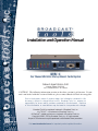
INC
®
Installation and Operation Manual
WVRC-4
Four Channel Web Voice Dial-up Remote Control System
Network Agent Version 3.68
Manual Update: 07/13/2011
PIC Firmware Version 1.12 or above
CAUTION! The following information pertains to the above version(s) of firmware. If your
unit is not loaded with this version of firmware, please contact Broadcast Tools for an upgrade.
Due to the dynamic nature of product design, the information contained in this
document is subject to change without notice. Broadcast Tools, Inc., assumes no
responsibility for errors and/or omissions contained in this document. Revisions
of this information or new editions may be issued to incorporate such changes.
Broadcast Tools® is a registered trademark of Broadcast Tools, Inc.
tiny TOOLS™ is a trademark of Broadcast Tools, Inc.
All Sentinel™ labeled products are a trademark of Broadcast Tools, Inc.
Copyright ® 1989 - 2011 by Broadcast Tools, Inc. All rights reserved.
No part of this document may be reproduced or distributed without permission.
Visit www.broadcasttools.com for important product update information.
WVRC-4 Installation and Operation Manual
Table of Contents
Section Title
Page #
Introduction .........................................................................................................................3
Safety Information...............................................................................................................3
Who to Contact for Help .....................................................................................................4
Product Overview................................................................................................................4
Inspection............................................................................................................................5
Installation ..........................................................................................................................5
Dial-up Programming ........................................................................................................10
Installing Factory Defaults ..........................................................................................10
Program Menu ............................................................................................................11
Menu Navigator ..........................................................................................................12
Dial Out Numbers.......................................................................................................12
Dial Out List................................................................................................................13
Settings.......................................................................................................................13
Access Code ..............................................................................................................14
Lap..............................................................................................................................14
Repeat ........................................................................................................................14
Silence Sensor ...........................................................................................................14
Power Fail ..................................................................................................................14
HU ..............................................................................................................................14
Monitor Access Code .................................................................................................14
Analog Debounce Timer.............................................................................................14
Pager Numbers and Data Strings .............................................................................15
Analog (metering) Setup ............................................................................................15
Status Setup...............................................................................................................17
Recording Voice Prompts...........................................................................................18
Configure DIP Switch Settings ...................................................................................18
Dial-up Operation..............................................................................................................21
WEB and Dial-Up Notice ..................................................................................................22
Web Setup ........................................................................................................................23
Configuration Info .......................................................................................................23
Ethernet Setup ...........................................................................................................25
Firmware.....................................................................................................................26
Java Applet.................................................................................................................26
Main Screen ...............................................................................................................27
Login Dialog ...............................................................................................................28
User Setup Dialog ......................................................................................................28
System Setup Dialog..................................................................................................29
Network Setup Dialog.................................................................................................30
Schedule Setup Dialog...............................................................................................31
Schedule Detail Dialog ...............................................................................................32
Analog (metering) Setup Dialog .................................................................................33
Status/Relay Setup Dialog .........................................................................................33
Virtual Channel Setup Dialog .....................................................................................34
About Dialog...............................................................................................................35
Specifications....................................................................................................................36
Warranty............................................................................................................................37
Declaration of Conformity .................................................................................................38
Connection Suggestion..........................................................................................Appendix
WEBSITE:
Visit our web site for
product updates and
additional information.
INDEX
e-mail: [email protected] voice: 360.854.9559 fax: 866.783.1742
2
WVRC-4 Installation and Operation Manual
INTRODUCTION
Thank you for your purchase of a Broadcast Tools® WVRC-4, Four Channel WEB
and Voice Dial-up Remote Control System (referred to as the WVRC-4 throughout
this manual). We’re confident that this product should give you many years of
dependable service. This manual is intended to give you all the information needed
to install and operate the Broadcast Tools® WVRC-4.
SAFETY INFORMATION
Only qualified technical personnel should install the WVRC-4. Any attempt to install
this device by a person who is not technically qualified could result in a hazardous
condition to the installer or other personnel, and/or damage to the WVRC-4 or other
equipment. Broadcast transmitters can operate at voltages that are potentially lethal.
Please ensure that proper safety precautions have been made before installing this
device. If you are unfamiliar with this type of equipment, please contact a properly
qualified engineer to handle the installation and setup of the WVRC-4.
For additional safety, it is strongly recommended that, in addition to setting the
WVRC-4 in to OP/PGM mode, the remote/local switch on any transmitter or high
voltage equipment also be set to local mode.
While the WVRC-4’s relays are physically capable of handling 250 VAC, this practice is extremely dangerous and should never be attempted. The pluggable euroblock
screw terminals are not designed to shield humans from potentially dangerous voltages. Contact with high voltages can cause serious injury or death. The maximum
recommended voltage for the WVRC-4 is 30V. Switching of high voltages should
only be done external from the WVRC-4 and in a manner that isolates the voltages
from accidental contact with humans.
WHO TO CONTACT FOR HELP
CAUTION!
Broadcast
Tools®
Products, as with any
electronic device, can
fail without warning.
Do not use this product
in applications where a
life threatening condition could result due to
failure. Serious injury
or death can occur if a
command channel is
activated while you are
performing
maintenance on your equipment. If you are performing maintenance
on your equipment, you
should
press
the
“OP/PGM” button on
the front panel of your
WVRC-4 forcing the
unit in to local mode.
The “PGM” LED will
illuminate. Local mode
prevents the unit from
performing relay commands.
If you have any questions regarding your product or you need assistance, please contact your distributor from whom you purchased this equipment.
If you would like more information about Broadcast Tools® products, you may
reach us at:
Broadcast Tools, Inc.
131 State Street
Sedro-Woolley, WA 98284-1540 USA
Voice: 360.854.9559
Fax: 866.783.1742
Internet Home Page: www.broadcasttools.com
E-mail:
[email protected]
THANK YOU FOR CHOOSING
BROADCAST TOOLS® BRAND PRODUCTS!
e-mail: [email protected] voice: 360.854.9559 fax: 866.783.1742
NOTE:
This manual should be
read thoroughly before
installation and operation.
INTRODUCTION
3
WVRC-4 Installation and Operation Manual
Product Overview
The WVRC-4 provides a cost-effective, half-rack solution for web based and/or
recordable voice response dial-up transmitter site control. The WVRC-4 was
designed from a users point of view, so all of the basic functionality you need is
included to control your site equipment, while including the accessories other manufacturers consider optional. Each analog (metering), status, silence sensor, temperature sensor and power failure input can be configured to email up to four individual email addresses, allowing different input alarms to be routed to different email
recipients.
The WVRC-4 is equipped with a browser based 100-event program scheduler for
relay control and alarm muting, along with an FIFO 8192-event alarm logger. The
user can enable a sound effect to play when an out of tolerance alarm is generated.
We have also provided SNMP capabilities to allow multiple units to be monitored
with any SMNP manager software package.
The WVRC-4 is equipped with four high-resolution analog (metering) channels,
while each of the four optically isolated status channels may be configured for 5 to
24vdc wet or dry (contact closures) status monitoring. The four control channels are
equipped with independent SPDT one-amp relays for each raise/on and lower/off
function for a total of eight relays. These relays may be latched, unlatched (Web
mode only) or momentarily closed.
The WVRC-4 is supplied with spoken words and phrases in English, while the user
is free to record words and phrases in any language. In addition, the WVRC-4 may
be programmed for dial-up operation via HyperTerminal, while the Java applet programming can be performed using your favorite web browser.
System expansion may be accomplished by cascading multiple WVRC-4’s on the
same telephone line and/or Ethernet switch.
WEBSITE:
Visit our web site for
product updates and
additional information.
OVERVIEW
e-mail: [email protected] voice: 360.854.9559 fax: 866.783.1742
4
WVRC-4 Installation and Operation Manual
Inspection
Please examine your WVRC-4 carefully for any damage that may have been sustained during shipping. If any is noted, please notify the shipper immediately and
retain the packaging for inspection by the shipper.
The package should contain the WVRC-4, this manual and/or CD, 25-foot temperature probe, 7 foot BLUE straight-through CAT 5 cable, 7 foot GRAY crossover
CAT 5 cable, RJ-11 telephone cable, 7-foot DB-9 straight-through serial cable and
the 12 VAC@1 amp wall transformer.
Installation
Surge Protection
The WVRC-4 has built-in resistance to voltage changes; we recommend that you
use a power surge protector or line conditioner on the incoming AC line. Lightning
strikes and other high surges in voltage levels will damage your WVRC-4 and connected equipment if it is not properly protected. For lightning protection devices,
check out www.polyphaser.com and www.itwlinx.com.
CAUTION!
Installation of the
WVRC-4 in high RF
environments should be
performed with care.
Shielded cable is suggested for all monitoring and control connections with all shields
tied to the station
ground terminal. The
station ground should
be connected to any
available rear panel
ground terminal or
chassis ground screw
using an 18 or 20-gauge
wire.
UPS Standby Power System
We recommend that you connect your WVRC-4 to a UPS system. While all operating and user parameters are stored in non-volatile EEPROM, brownout conditions
and lightning induced spikes can disable or damage equipment.
A UPS helps minimize the risk to the WVRC-4 and has the added benefit that it will
then be able to notify you of the power outage by email, phone or pager depending
on your system configuration.
INSPECTION
e-mail: [email protected] voice: 360.854.9559 fax: 866.783.1742
5
WVRC-4 Installation and Operation Manual
Front panel indicators, controls and connectors
Name
Type
Description
K1 - K4 Raise
LED
Illuminates when corresponding raise relays are activated.
K1 - K4 Lower
LED
Illuminates when corresponding lower relays are activated.
Status 1 - 4
LED
Illuminates when corresponding status inputs are activated.
NOTE: Counting from the top (1) down to the bottom (4).
TX
LED
Flashes during server/control processor data exchange.
RX
LED
Flashes during server/control processor data exchange.
REC
LED
Illuminated when in voice record mode.
RING
LED
Illuminated when a telco call is being received.
ACS
LED
Illuminated when a valid ACCESS code is entered.
HK
LED
Illuminated when the unit is off-HOOK.
DV
LED
Illuminated when a valid DTMF tone is detected.
ALM
LED
Illuminated when unit is in an alarm condition.
PWR
LED
Illuminated when valid power is applied to the power jack.
PGM
LED
Illuminated when the unit is in programming mode.
SS
LED
Illuminated when adequate audio is applied to the SS input, OFF
when the level is to low and flashing if in an SS alarm condition,
if enabled.
PF
LED
Illuminated with no power applied, OFF when adequate
DCvoltage is applied to the PF jack and flashing if a Power
Failure has been detected, if enabled.
OP/PGM
Push Button
SS Mon
Control
Sets the silence sensor audio sent to the phone line, when
enabled.
SS Sense
Control
Sets the audio trip point of the silence sensor
PGM
Fem DB-9
VOICE PGM
RJ11
WEBSITE:
Visit our web site for
product updates and
additional information.
Toggles between operate and programming (local) mode.
RS-232 host PC programming port.
Voice record TT phone port, user provided TT telephone
INSTALLATION
e-mail: [email protected] voice: 360.854.9559 fax: 866.783.1742
6
WVRC-4 Installation and Operation Manual
Rear panel indicators, controls and connectors
Name
Type
PF
2.1mm Jack
SSL/GND/SSR
Connector
Description
Power Failure power jack (optically-isolated). 6 - 12 VDC.
Unbalanced left/ground/right silence sensor audio input (BOT)
LAN/WAN
RJ45
Network ETHERNET port 10/100baseT, LAN/WAN
TELCO LINE
RJ11
Connects to a POTS telephone line
A1 - A4
Connector
Analog (metering) inputs one thru four (TOP)
GND
Connector
Analog (metering) ground reference terminals (TOP)
1A - 4A
Connector
Status opto-isolators. When configured for DRY (factory default)
this terminal is ground. When configured for WET (floating), this
terminal is the Anode via a 2.2K ohm current limiting resistor.
(BOTTOM)
1B - 4B
Connector
Status opto-isolators. This terminal is always the cathode
(BOTTOM)
R1NC - R4NC
Connector
Normally closed, dry relay contacts. Raise function (TOP)
R1CM - R4CM
Connector
Common (wiper), dry relay contact. Raise function (TOP)
R1NO - R4NO
Connector
Normally open, dry relay contact. Raise function (TOP)
L1NC - L4NC
Connector
Normally closed, dry relay contact. Lower function (BOTTOM)
L1CM - L4CM
Connector
Common (wiper), dry relay contact. Lower function (BOTTOM)
L1NO - L4NO
Connector
Normally open, dry relay contact. Lower function (BOTTOM)
CONFIG
Dipswitch
Used to configure the unit. Refer to table of contents.
TEMP SENSOR 3.5mm Jack
Temperature probe input jack. T/R/S.
PWR/12VAC
System power supply input. 12 volts AC
2.1mm Jack
INSTALLATION
e-mail: [email protected] voice: 360.854.9559 fax: 866.783.1742
7
WVRC-4 Installation and Operation Manual
Connecting your WVRC-4 to other equipment
Analog (metering) inputs
CAUTION! Analog input (metering) samples may be elevated several hundred
volts above ground on some external equipment. Permanent damage may occur to
the WVRC-4 and/or external equipment if a high voltage metering source is connected to the WVRC-4! Failure to observe this warning may also cause injury to the
installer or other personnel.
CAUTION!
DO NOT CONNECT
SAMPLE VOLTAGES
IN EXCESS OF POSITIVE 10 VDC OR
DAMAGE
MAY
OCCUR TO YOUR
WVRC-4.
CAUTION! Floating Grounds
Except for all status (wet) inputs, none of the WVRC-4’s metering inputs will accept
a floating ground. Damage to the WVRC-4 or your equipment may result from connecting a floating ground output to the WVRC-4. If you require metering inputs
with equipment that has a floating ground, an isolation DC amplifier must be used.
Four analog (metering) channels are connected to the WVRC-4 via depluggable
euro-block screw terminals. Connect the positive side of the source to the desired
channel terminal labeled ANx (where x is the channel number 1 through 4) and associated GND (ground) terminal. Each analog (metering) input can handle up to (positive only) 10 volts DC and must be ground referenced. Connect your metering
ground to the associated ground terminal. Inputs are self-calibrating and are based
on an internal A/D converter with a precision, low-drift voltage reference, so the
reading should not drift over time or with temperature. Analog (metering) setup is
performed by connecting the sample voltage to the analog (metering) input, then
programming the WVRC-4 for the desired value (reading).
WEBSITE:
Visit our web site for
product updates and
additional information.
INSTALLATION
e-mail: [email protected] voice: 360.854.9559 fax: 866.783.1742
8
WVRC-4 Installation and Operation Manual
Status Inputs
Each of the four optically isolated status inputs can be configured to accept either a
contact closure (dry = default) or a (floating, wet). Attach your dry contacts to the
desired status channels StxA and STxB (where x is the status input) terminals.
Each input is equipped with a four-position header. Each input is labeled IN-x
(where x is the status input) and the header pins are labeled 1,2,3,4. The factory
default is a DRY input (switch, relay contact) with jumpers between 1 & 2 and 3 &
4. In the dry configuration, the “A” terminal is ground while the “B” terminal is the
cathode of the opto diode (pulled up to 5 volts through a 2.2K resistor).
To change the status input to (floating) WET (user supplied voltage between 5 and
24vdc), remove both jumpers and place ONE jumper over pins 2 & 3. Connect the
positive voltage to terminal “A” (anode) and ground or minus voltage to terminal
“B”(cathode). ! NOTE: Please observe proper polarity.
Raise/Lower Relays
Raise and lower relays K1 through K4 are supplied with SPDT dry contacts.
Equipment to be controlled by the RAISE relays should be connected to the TOP terminals labeled RxNC, RxCM and RxNO (where x is the channel number), while
equipment to be controlled by the LOWER relays should be connected to the BOTTOM terminals labeled LxNC, LxCM and LxNO (where x is the channel number).
NOTE: If mechanical latching relays are required, we suggest the Broadcast
Tools LR-5 (4PDT & 1SPST) mechanical latching relay.
Power Failure Input
Connect a user supplied 6 to 12 volts DC only power source (center positive) to the
power failure input labeled PF. The barrel connector size is 2.1mm ID x 5.5mm OD.
An inexpensive 6 to 12 volts DC wall transformer of any current of 50 ma or more
will work.
NOTE: The primary (120vac) of the wall transformer should be connected to
the utility company side of your service. An UPS is suggested to power the
WVRC-4 during power outages.
Silence Sensor Inputs
Connect your unbalanced monaural or stereo audio source to the terminals labeled
SSL, GND and SSR. The level should be between –10 and +8 dbu. The input
impedance is approximately 10K ohms. When the SS is activated, you can adjust
the SS Sense trimmer for an illuminated front panel SS led. If the SS led is out, the
signal is low and if it’s flashing, it in an alarm condition (if enabled). The silence
sensor signal can only be aurally monitored in dial-up mode. The front panel SS
Mon trimmer should be adjusted for a comfortable level at the caller end.
CAUTION! If the SS MON level is too high, the unit may have trouble detecting
DTMF tones. NOTE: The DTMF guard time jumper is factory set to the “MED”
position for enhanced tone detection. In some applications, your may need to move
this jumper.
INSTALLATION
e-mail: [email protected] voice: 360.854.9559 fax: 866.783.1742
9
WVRC-4 Installation and Operation Manual
TEMP Sensor Probe Input
Insert the temperature probes (25 foot cable) mini (3.5mm) plug in to the rear panel
jack labeled “TEMP” (-40°F to +190°F (-40°C to +85°C).
NOTE: Please limit the total length of cable to 50 feet. Please contact the factory for the proper extension cable. The temperature probe should only be
installed or removed with the power supply disconnected from the WVRC-4.
POTS Telephone Line RJ11
Connect one end of the supplied RJ11 modular cable to the rear panel RJ11 jack
labeled “LINE” and the other end to the telephone line.
NOTE: Some “cell phone services” severely distort DTMF control tones
resulting in unreliable control. If you plan on using the cellular system for your
POTS connection, you may have to experiment with various service providers
to get reliable control. With some cellular phone services, you may need to
change the DTMF guard time jumper to the “FAST” position. We recommend
using a product from Telular “Phonecell® SX5D or SX7” which is designed for
the GSM system (www.telular.com/).
PGM, RJ11, TT phone
Connect the modular cord of the user supplied TT telephone to the front panel RJ11
jack labeled “PGM”
PGM, RS-232 female DB-9 connector
Connect one end of the supplied male/female straight-thru serial cable to this connector and the female end to a user provided PC (this may not be needed if the user
elects to program the dial-up portion via telnet (INTERNET).
NETWORK connector
Connect one end of the supplied CAT5 (straight or xover) cable to desired ETHERNET port.
WEBSITE:
Visit our web site for
product updates and
additional information.
POWER connector (12VAC)
Connect the supplied 12VAC power supply cord in to the WVRC-4’s power jack
labeled “12 VAC @ 1 amp”, then plug the transformer in to a source of 120vac
60Hz. Verify that the front panel green power led is illuminated.
INSTALLATION
e-mail: [email protected] voice: 360.854.9559 fax: 866.783.1742
10
WVRC-4 Installation and Operation Manual
Dial-Up Programming
Connect the supplied 12VAC power supply cord in to the WVRC-4’s power jack
labeled “12VAC 1 AMP”, then plug the transformer in to a source of 120 vac 60Hz.
Verify that the green “PWR” led is illuminated.
Follow the steps below to configure the WVRC-4 for dial-up operation:
Installing factory (Dial-up only) defaults.
Remove power from the unit. Hold down the “PGM” button down while reinstalling
the power plug. The “PGM” button must be held down for a few seconds after the
power is restored. When the PGM button is released, the PGM LED will blink
twice to show that the defaults were loaded.
CAUTION! If you reinstall factory defaults, the standard factory recorded
voice prompts are not reloaded. The user MUST re-record the voice prompts.
NOTE: The dial-up programming may be accomplished locally using the RS232 serial port or via the web using Telnet.
Telnet “DIAL-UP” programming via LAN/WAN.
NOTE: Step by step HyperTerminal “Telnet” setup instructions are available
on-line at www.broadcasttools.com under “Downloads
If you have followed the above HyperTerminal “Telnet” steps, the main WVRC-4
menu will be displayed on the next page.
Local “DIAL-UP” programming via the front panel RS-232 “PGM” port.
1 - Connect the supplied straight-through serial cable to an available com port on
your PC (If the PC isn’t equipped with a serial (com) port, contact your local PC
store or Broadcast Tools for a USB to RS-232 serial adapter) and connect the other
end to the front panel “PGM” DB-9 female serial connector.
2 - Start HyperTerminal (or your favorite com program) configured for: 9600,8,N,
1, flow control to NONE, Emulation set to ANSI and under ASCII setup, check the
box “echo typed characters locally”.
NOTE: Step by step “COM” port HyperTerminal setup instructions are available on-line at www.broadcasttools.com under “Downloads”.
PROGRAMMING
e-mail: [email protected] voice: 360.854.9559 fax: 866.783.1742
11
WVRC-4 Installation and Operation Manual
3 - Press the front panel “PGM” button. The front panel “PGM” LED will illuminate, while the program menu on the next page will be displayed:
Program Menu:
Menu navigation:
Press escape (ESC) to jump back to the previous menu selection, and if pressed from
the PGM Menu, program mode will be exited.
Dial Out Numbers
These are the numbers that will be dialed when alarms are generated. The dial-out
list will select numbers from this pool to call out during an alarm condition. Up to
32 digits can be used in each number along with a comma (,) for one second and a
semi-colon (;) for 5 second pauses. When (1) is selected from the PGM Menu, the
Dial-Out number list will be displayed.
WEBSITE:
Visit our web site for
product updates and
additional information.
PROGRAMMING
e-mail: [email protected] voice: 360.854.9559 fax: 866.783.1742
12
WVRC-4 Installation and Operation Manual
Dial-Out List
When (2) is selected from the PGM Menu, the Dial-Out List is displayed. This is
where you determine what number is dialed for a selected input alarm. 1 - 4 is used
for status inputs, A-D are used for Analog (metering) inputs, S for Silence Sensor, P
for Power Fail and T for Temperature. The numbers after the Analog letter selection
show which analog channel is being selected. Only enter the letter designation to
select the analog dial-out list to program.
Example: When status input 1 changes state, the WVRC-4 will dial the number
stored in the dial out number location 1.
Settings:
PROGRAMMING
e-mail: [email protected] voice: 360.854.9559 fax: 866.783.1742
13
WVRC-4 Installation and Operation Manual
When item (3) is selected from the PGM Menu, the Access Code, Lap, Ring Count, Repeat
Count, Silence Sensor Delay Time, Power Fail Time, Hang up time, Monitor access code
and Analog Debounce Time can be programmed.
The “Access Code” may be changed from the default code of 123, allowing a user all control functions.
“Lap” defines the number of times the WVRC-4 will go through all of the numbers in the callout list when calling out an alarm if it does not receive an acknowledgement.
NOTE: Alarms are acknowledged by pushing the star (*) key when an alarm is called
out.
“Ring” defines the number of rings required before the WVRC-4 answers a call.
“Repeat” is the number of times the voice message will be repeated when the alarm is
called out. Since there is no way of knowing when the remote party answers the phone line,
the WVRC-4 will start playing the alarm message a few seconds after dialing for the
“Repeat” number of times. So when an alarm call is answered, you may pick up the phone
in the middle of an announcement or there may be a few seconds of silence before the start
of the next message. Once the star (*) is entered to acknowledge the alarm, it will stop playing the message. You can now enter your access code and perform control functions or
polling.
“Silence” Time is programmed with a value of 0-9 with a 0 being OFF and 1-9 with values are as follows: 1 = 10 sec, 2 = 30 sec, 3 = 60 sec, 4 = 1.5 min, 5 = 2.0 min, 6 = 2.5 min,
7 = 3 min, 8 = 4.0 min and 9 = 5.0 min. Note: The silence sensor audio must be restored
for a minimum of 10 seconds and the alarm must be acknowledged before it is cleared.
“Power Fail” Time is programmed in 10 second values. For example, 2 = 20 seconds of
silence or power failure to generate an alarm, 9 = 90 seconds. If it is set to “0”, the alarm
will be turned off and will not call out.
The “HU” value refers to the number of minutes the WVRC-4 will remain off-hook after
answering the call before hanging up automatically. Normally a CPC signal is sent from the
Central Office to signal it to hang up. If you are connected to a standard phone line, you
can set the HU to 0, and it will remain off-hook until the CPC signal is received. If it is connected on the other side of a PBX system that does not pass the CPC signal, then a value of
1-9 minutes should be set into HU to keep it from remaining off hook and causing the line
to be busy. The HU timer will be reset each time a valid DTMF is decoded showing activity. Once there is no more activity, the WVRC-4 will time-out after the HU time value and
force a hang-up.
WEBSITE:
Visit our web site for
product updates and
additional information.
The “Monitor Access Code” is an alternate access code that allows a user only to
monitor or poll the various inputs. No control functions can be performed unless a valid
Control Access code has been entered.
The “Analog (metering) Debounce Timer” is the number of ten second increments required
for the analog inputs to accept an alarm condition. For example, if it is set to 3, an Analog
input must be in an alarm condition for 30 seconds before an alarm will be generated.
NOTE:
alarm.
If set to “0”, analog alarms will be disabled and will not call out during an
PROGRAMMING
e-mail: [email protected] voice: 360.854.9559 fax: 866.783.1742
14
WVRC-4 Installation and Operation Manual
Pager Numbers and Data Strings
When item 4 is selected from the PGM Menu, the pager number and pager data can
be entered. To force the WVRC-4 to dial a pager number, enter a “9” in the dial-list.
That will cause the WVRC-4 to first dial the number in the page list, then it will generate two digits to identify the source of the alarm; 11-14 for analog (metering inputs
one through four, 19 for a temperature alarm, 20 for a power failure, 21-24 for status inputs one through four and 29 for a silence sensor alarm. The last item to be
sent is the pager data. This can be used to identify the station or location of the
WVRC-4. The comma (,) can be used any place in the dialing strings to place a one
second pause and the semi-colon (;) for a five second pause.
Analog (metering) Setup
When “5” is selected from the PGM Menu, the analog (metering) calibration and
Alarm Set Points can be configured.
Select “1” to calibrate any of the analog (metering) inputs for the desired value.
Selecting a “1” will produce the following prompt “Select Ch 1-4 followed by the
desired 4 digit value”. Enter the channel number, then the desired value.
PROGRAMMING
e-mail: [email protected] voice: 360.854.9559 fax: 866.783.1742
15
WVRC-4 Installation and Operation Manual
NOTE: The decimal point may be added and is not considered part of the four
digits
Example: To calibrate analog (metering) channel 1, enter 1, then the desired fourdigit reading.
Example: 75.00 would be seventy-five; 750.0, seven hundred and fifty while 7500
would be seventy five hundred.
NOTE: The correct value on the analog (metering) input MUST be present for
several seconds prior to entering OP/PGM mode. Once program mode is
entered, the analog (metering) inputs are locked and changes made while in
program mode will not be read. If there is no signal on the input, an error message will be displayed.
WEBSITE:
Visit our web site for
product updates and
additional information.
Enter a “2” from the Analog Set-Up menu to establish alarm set points. Analog
(metering) input set points are set up using items 1 à 4, representing analog (metering) inputs one through four.
Example: If you’re reading is normally 7000 V, and you want it to alarm when the
voltage drops below 6300 (-10%) or over 7350 (+ 5%), then enter 6300/7350.
PROGRAMMING
e-mail: [email protected] voice: 360.854.9559 fax: 866.783.1742
16
WVRC-4 Installation and Operation Manual
Temperature alarm set points are set up in the analog (metering) “Alarms” menu section. Item “9” sets the low and high set points. The entry is a four-digit number with
the first digit being the F or C designator. If the first digit is a “0” then the number
is assumed to be Fahrenheit. If the first digit is a “1” then Celsius is assumed.
Example: To enter low and high alarm set points of 30F and 95F, enter 0030/0095.
To enter low and high alarm set points of 10C and 40C enter 1010/1040. Do not
enter the “/”, it will be entered automatically.
Status Setup
When “6” is selected from the PGM Menu, the Status inputs are set up for either
Normally Open or Normally Closed and for the amount of DEBounce time the input
has to be in an “alarm” state for an alarm to be generated.
When “1” is selected from the menu: Make changes or press Escape to accept current values. If changes are made, all four values must be entered.
PROGRAMMING
e-mail: [email protected] voice: 360.854.9559 fax: 866.783.1742
17
WVRC-4 Installation and Operation Manual
When “2” is selected from the menu, the following is displayed:
Make changes or press ESC to accept current values. If changes are made, all four
values must be entered. Valid settings are 0 through 9. A “0” will turn off the status
input so that it will not generate an alarm. A 1-9 will set the “DEBounce” period
from 10 to 90 seconds. That means that the input must be in the alarm state continuously for that amount of time for an alarm to be generated. Any interruption will
cause the timer to reset.
Recording Voice Prompts (Messages):
To record voice messages into the WVRC-4, follow the steps below:
1 - Connect a TT telephone to the front panel RJ-11 jack.
2 - Press the front panel “OP/PGM” button; this should illuminate the front panel
“PGM” LED.
3 - Enter the two-digit address of the message you wish to program. The list of
messages are below.
4 - The Red “REC” LED will illuminate. As soon as it lights, begin speaking
the new message into the telephones mouth piece. For best results, stay at least
three inches from the mouthpiece of the telephone.
5 - When finished, press the “OP/PGM” button again, the “REC” and “PGM” LED’s
will extinguish.
WEBSITE:
Visit our web site for
product updates and
additional information.
NOTE: If the time allotted for the message you are recording elapses before the
button is pressed, it will turn off automatically. For example, to record the greeting message, press the “OP/PGM” button, enter 00 on the keypad, speak the new
greeting message into the handset and press the “OP/PGM” button again.
Example: To hear the current greeting message, press the “OP/PGM” Program button and enter *00. The current greeting message will play.
PROGRAMMING
e-mail: [email protected] voice: 360.854.9559 fax: 866.783.1742
18
WVRC-4 Installation and Operation Manual
Here is a list of the voice messages that are included with the WVRC-4.
Message
Greeting
On
Off
Raise
Lower
Access Accepted
Silence Alarm
Power Fail Alarm
High
Low
Status Input 1
Status Input 2
Status Input 3
Status Input 4
Status Input 5
Status Input 6
Status Input 7
Status Input 8
Analog Input 1
Analog Input 2
Analog Input 3
Analog Input 4
Analog Input 5
Analog Input 6
Analog Input 7
Analog input 8
Engineering Unit 1
Engineering Unit 2
Engineering Unit 3
Engineering Unit 4
Engineering Unit 5
Engineering Unit 6
Engineering Unit 7
Engineering Unit 8
Number 0
Number 1
Number 2
Number 3
Number 4
Number 5
Number 6
Number 7
Number 8
Number 9
Address
00
01
02
03
04
05
06
07
08
09
11
12
13
14
15
16
17
18
21
22
23
24
25
26
27
28
31
32
33
34
35
36
37
38
40
41
42
43
44
45
46
47
48
49
Length (Sec)
10
2.6
2.6
2.6
2.6
5
5
5
5
5
5
5
5
5
5
5
5
5
5
5
5
5
5
5
5
5
2.6
2.6
2.6
2.6
2.6
2.6
2.6
2.6
2.6
2.6
2.6
2.6
2.6
2.6
2.6
2.6
2.6
2.6
PROGRAMMING
e-mail: [email protected] voice: 360.854.9559 fax: 866.783.1742
19
WVRC-4 Installation and Operation Manual
Message
Relay 1
Relay 2
Relay 3
Relay 4
Relay 5
Relay 6
Relay 7
Relay 8
Temperature
Degrees Celsius
Degrees Fahrenheit
Minus
Enabled
Disabled
Point
Temperature Alarm
Address
51
52
53
54
55
56
57
58
60
61
62
63
64
65
66
67
Length (Sec)
5
5
5
5
5
5
5
5
2.6
2.6
2.6
2.6
2.6
2.6
2.6
2.6
“CONFIGURE” DIP Switch settings:
NOTE: The “UP” position is OFF
DIP 1 - Feature creep
DIP 2 - OFF = Voice Temperature in Fahrenheit, ON = Celsius.
DIP 3 - If OFF, description messages will be played when controlled via dial-up. If
ON, raise and lower description messages will not be played.
DIP 4 - OFF = Server control, ON = PC control via DB9.
WEBSITE:
Visit our web site for
product updates and
additional information.
DIP 5 - OFF = Normal operation, ON = DB9 RS-232 to web server.
DIP 6 - Feature creep
DIP 7 - Feature creep
DIP 8 - If OFF, input alarms are active. If ON, alarms will not respond.
PROGRAMMING
e-mail: [email protected] voice: 360.854.9559 fax: 866.783.1742
20
WVRC-4 Installation and Operation Manual
When the WVRC-4 is called, it will answer on the number of rings programmed.
When it answers, enter the default security code 123 for this example. The access
LED will illuminate once a valid security code is entered, and the “Access Accepted”
Message will play. After a valid access code is received, the addressed unit will generate a DTMF “AB” which will cause any other units in parallel to hang up.
NOTE:
Multiple WVRC-4’s may be daisy-chained to allow for channel
expansion. Use an unique access code for each additional WVRC-4.
Raise and Lower Relays are controlled with single digits 1-4 followed by * for
Lower or # for Raise. Once a single channel number has been entered, you can now
enter * or # to operate that channel until a new channel number has been entered.
The analog value for the selected channel will play each time a number between 1
and 4 is entered as long as DIP3 is OFF.
Example: Enter 1 – analog value 1 will play - * - The number 1 Lower relay will
be held on as long as “*” received, # - Raise relay held on as long as “#” received.
If DIP3 is OFF, the associated relay message plus “raise” or “lower” will be played
after the * or # is released. To find out the new analog values just press 1 again and
it will speak the new value.
Audio I/O functions are controlled with the following codes, once the security code
has been entered:
07 – Silence sensor monitor audio to telco ON
08 – Silence sensor monitor audio to telco OFF
NOTE: The silent sensor audio will be turned off when the WVRC-4 hangs up.
The Status inputs, Analog (metering) inputs, silence sensor and power fail inputs can
be polled.
Polling Silence Sensor Alarm: 910
Polling Status inputs: 911 - polls status input 1, 912 - polls status input 2 ….
914 polls input 4.
NOTE: When polling status inputs, the actual alarm state is returned, regardless of the input being high or low. So if the input is set as Normally Closed,
and it is Open when polled, it will say “Input x is “ON”.
Polling Power Failure: 919
Manual Hang-up: 920 will cause the WVRC-4 to hang up.
Polling Analog (metering) inputs:
921 - polls analog input 1, 922 - polls analog input 2 ….. 924 polls analog input 4.
Polling temperature: 929
PROGRAMMING
e-mail: [email protected] voice: 360.854.9559 fax: 866.783.1742
21
WVRC-4 Installation and Operation Manual
DTMF Control of Alarm Enable Registers
All of the Alarm call-outs can be enabled disabled or polled remotely using DTMF
control. First enter the access code. Once the unit is un-locked, the status alarms
can be controlled by entering 77 followed by the status number 1 through 4 and 1
for enable, 0 of disable or 9 for poll. The analog alarms can be controlled by entering 78 followed by the analog number 1 through 4, and 1 for enable, 0 for disable or
9 for poll. Power fail and silent sensor are controlled with 79 followed by 1 for
power fail, 2 for silent sensor, then 1 for on, 0 for off or 9 for poll.
NOTE:
To clear an alarm, press the star (*) key.
Examples are listed below:
Enable Status 4 alarm:
Poll Status 4 alarm enable:
Enable Analog 1 alarm:
Poll Analog 1 alarm enable:
Enable Power Fail Alarm:
Poll Power Fail alarm enable:
Enable Silent Sensor Alarm:
Poll Silent Sensor Alarm enable:
NOTE:
7741.
7749
7811.
7819
7911.
7919
7921.
7929
Disable Status 4 alarm: 7740
Disable Analog 5 alarm: 7810
Disable Power Fail alarm: 7910
Disable Silent Sensor Alarm: 7920
To clear an alarm, press the star (*) key.
A voice message will be played indicating the action taken.
Web and/or Dial-up Notice
The WVRC-4 can be used for dial-up only, web only or a combination of both. It is
suggested that the user configure for both dial-up and WEB operation. Some features such as the scheduler and logger will require the user to configure the web portion of the WVRC-4 even if web access isn’t being used.
WEBSITE:
Visit our web site for
product updates and
additional information.
NOTE: If the scheduler is to be used for time sensitive applications, the use
of a NTP server for time is highly recommended.
PROGRAMMING
e-mail: [email protected] voice: 360.854.9559 fax: 866.783.1742
22
WVRC-4 Installation and Operation Manual
WEB Setup
The WVRC-4 firmware supports an HTTP (web) interface on TCP port 80, which is
user programmable. The default page contains a Java applet used to monitor and
control the WVRC-4.
Ethernet setup
The WVRC-4 is factory set for IP:
Subnet:
192.168.1.55
255.255.255.0
CAUTION! Assigning an IP address already in use by another device may cause
problems with your network!
Information youʼll need to configure the WVRC-4
1 - An available Static IP address to assign to the WVRC-4.
The WVRC-4 is factory set for IP:
192.168.1.55
Subnet:
255.255.255.0
NOTE: If a static IP isn’t available, consider using http://www.dynip.com/
2 - The network’s subnet mask.
3 - Your network’s gateway address (essential for proper operation).
4 - The IP address of the email server.
5 - The SMTP port used by your email server (usually 25).
6 - Up to four email addresses to which you want to send alarms.
NOTE: The network administrator may be required to enter the IP address
of the WVRC-4 into the SMTP server to allow email forwarding. In some
installation, an email forwarding service such as http://www.smtp.com/ may be
required for the email function to operate properly.
7 - IP address of a NTP timeserver, if used.
NOTE: Here is the IP address for the NIST NTP server 132.163.4.103
(http://tf.nist.gov/service/time-servers.html). (You may also enter the time and date
manually if Internet service is not available). The RTC isn’t battery backed-up. You
should consider a UPS to maintain time/date.
WEB SETUP
e-mail: [email protected] voice: 360.854.9559 fax: 866.783.1742
23
WVRC-4 Installation and Operation Manual
The WVRC-4’s RJ-45 (Network) is normally attached to a DSL/Cable router,
Ethernet hub or switch. The supplied “Device Installer” software should be used to
configure the IP address of your WVRC-4. The “Device Installer” version 4.1.0.12
software or greater is also available on our web site: www.broadcasttools.com,
under downloads or on the supplied CD.
NOTE:
The Device Installer application requires Microsoft’s .NET
Framework version If you do not already have .NET Framework version 1.1 or
greater (dotnetfx.exe) installed, you can download it from the link: v1.1
1 - Install the “Device Installer” software on the PC used for the WVRC-4 setup.
NOTE:
The WVRC-4 applet requires a compatible Java Runtime
Environment Version 6 update 1 or greater). If your browser is lacking Version
6 update 1 or greater, we have provided a link to download the required application: http://www.java.com/en/download/index.jsp then click on the
“Download Now” button, then follow the prompts.
2 - Connect the supplied BLUE straight-through CAT 5 cable to the RJ-45 connector on the WVRC-4 labeled (Network) and the other end to your hub or switch.
NOTE:
If you are attaching the WVRC-4 directly to your computer, you
MUST use the supplied GRAY Xover CAT 5 cable and set your PC’s IP for
192.168.1.1
3 - Connect the supplied 12 VAC @ 1amp power supply to the WVRC-4’s power
jack labeled 12VAC/1 Amp. Verify that the front panel power LED and left “LINK”
LED above the “NETWORK” RJ-45 are illuminated
WEB SETUP
e-mail: [email protected] voice: 360.854.9559 fax: 866.783.1742
24
WVRC-4 Installation and Operation Manual
Ethernet port LED indicator functions
4 - Start the “Device Installer” software.
a - Click on “SEARCH”
b - When the WVRC-4 is found, click on the listed device. If more than one WVRC-4
is found, refer to the MAC address label attached to the WVRC-4 RJ-45 case and click
on the desired WVRC-4, which should be highlighted.
NOTE: The cover must be removed to locate the MAC address label, or check
the “MAC” label attached to the top of chassis.
c - Click on the “ASSIGN IP” button, then follow the instructions for setting a static IP address, along with the subnet and gateway, if applicable.
d - After the WVRC-4 has rebooted, click the “SEARCH” button, the configured
WVRC-4 should be listed.
NOTE: You may have to click the search button more than once after the reboot.
NOTE: You can also open your browser and type in the assigned IP address
in the “ADDRESS” area of your browser. Example: 192.168.1.101
5 - If you are behind a firewall or router, you will need to port forward not only port
80, also open ports 3001 and 3002 and set the SUN Java to direct.
NOTE: To set up port forwarding, refer to the manual supplied with the firewall or router.
6 - To change the WVRC-4 from port 80, contact the factory
WEBSITE:
Visit our web site for
product updates and
additional information.
7 - To access the WVRC-4, open your browser and type in the assigned IP address
in the “ADDRESS” area of your browser. Example: 192.168.1.55
8 - If things are working correctly, you should see the WVRC-4 web page.
NOTE: On some machines and browsers, this may take a few seconds.
9 - Log in using the default user name = wvrc4 or admin (lower case) and the
password = wvrc4 (lower case) or 1234.
NOTE: If you change the “OWNER” user name and password, be sure to
write it down.
10 – Follow the descriptions on the following pages to set up the WVRC-4.
WEB SETUP
e-mail: [email protected] voice: 360.854.9559 fax: 866.783.1742
25
WVRC-4 Installation and Operation Manual
The WVRC-4 software consists of two components – firmware running in the
XPORT web server and a Java applet hosted on the XPORT, running in a web
browser. The following describes the operation of both components.
CAUTION! NEVER DOWNLOAD FIRMWARE UPDATES OR CHANGES
TO THE XPORT WEBSERVER. DOING SO DELETES ALL SOFTWARE
AND VOIDS ALL WARRANTIES FROM BROADCAST TOOLS, INC.
Firmware
The
WVRC-4
firmware
starts
when
the
Xport
is
booted.
The firmware communicates with the WVRC-4 microcontroller via its internal serial port and provides several network interfaces via its Ethernet port.
The WVRC-4 firmware supports an HTTP (web) interface on TCP port 80. The
default page (index.html) contains a Java applet used to monitor and control the
WVRC-4. The applet is fully described in the next section.
CAUTION! NEVER DOWNLOAD FIRMWARE UPDATES OR CHANGES
TO THE XPORT WEBSERVER UNLESS REQUESTED BY BROADCAST
TOOLS. DOING SO DELETES ALL SOFTWARE AND VOIDS ALL WARRANTIES FROM BROADCAST TOOLS, INC.
Java applet
The Java applet is the primary user interface. The following pages describe each of
the items of each screen displayed by the applet:
WEBSITE:
Visit our web site for
product updates and
additional information.
WEB SETUP
e-mail: [email protected] voice: 360.854.9559 fax: 866.783.1742
26
WVRC-4 Installation and Operation Manual
Main Screen
The main screen displays information identifying the site, gauges and LED’s representing analog (telemetry) values, status state, buttons representing relays and buttons to login, set up, and control the WVRC-4.
Site ID
Station Call Letters
Current Time
Enable Audible Alarms
Analog Labels
Analog Display
Analog Text
Analog Unit Labels
Status Labels
Status LED’s
Relay Button Labels
Relay Buttons
Virtual Labels
Virtual Displays
Virtual Text
Virtual Unit Labels
Login Button
Logout
User Setup
User defined identification
Call letter identification
Current time set in the WVRC-4
Specifies whether alarms cause a beeping noise or are
silent
User defined labels for analog inputs
Graphical representation of the defined analog metering
values
Numeric representation of the defined analog values
User defined labels giving analog units of measure
User defined labels for status inputs
On/Off indicators showing current state of status inputs
User defined labels for relays
Buttons to momentarily activate or latch relays
User defined labels for virtual values
Graphical representation of current virtual values
Numeric representation of current virtual values
User defined labels giving virtual units of measure
Displays the Login dialog described below
Logs the user out
Displays the User Setup dialog described below
WEB SETUP
e-mail: [email protected] voice: 360.854.9559 fax: 866.783.1742
27
WVRC-4 Installation and Operation Manual
System Setup
Network Setup
Schedule Setup
Analog Setup
Status/Relay Setup
Virtual Setup
Silence Alarms
Show Log
to allow pop-ups
User Defined Button
About
Displays the System Setup dialog described below
Displays the Network Setup dialog described below
Displays the Schedule Setup dialog described below
Displays the Analog Setup dialog described below
Displays the Status/Relay Setup dialog described below
Displays the Virtual Setup dialog described below
Sends the Silence (clear) Alarms command to the WVRC-4
Displays the event log as a text file in the browser
(IP/log.txt). Be sure
Displays a user-defined label and activates a user-defined
URL when clicked (Example: URL of site camera, etc)
Displays the About dialog described below
Login Dialog
The Login dialog asks the user for a username and password. This information is
used to determine the user’s privilege level and the commands the user can execute.
Default Username
Default Password
wvrc4 or admin (lower case)
wvrc4 (lower case) or 1234
User Setup Dialog
WEBSITE:
Visit our web site for
product updates and
additional information.
WEB SETUP
e-mail: [email protected] voice: 360.854.9559 fax: 866.783.1742
28
WVRC-4 Installation and Operation Manual
The User Setup dialog is used to assign passwords and privilege levels for up to
eight users. Privilege levels allow the following activities:
• None - Monitor analog, status, and virtual inputs
• User - Monitor analog, status, and virtual inputs, activate relays
• Super - Monitor analog, status, and virtual inputs, activate relays, perform setup
functions excluding User Setup
• Owner - Monitor analog, status, and virtual inputs, activate relays, perform setup
functions including User Setup
Username
Password
Buttons
OK
Cancel
Specifies a 15-character, case-sensitive username.
Specifies a 15-character, case-sensitive password.
Selects a privilege level.
Saves the settings and exits.
Exits without saving settings.
Default Username
Default Password
wvrc4 or admin (lower case)
wvrc4 (lower case) or 1234
CAUTION!
Broadcast Tools
products, as any electronic device, can fail
...
NOTE:
For safety, DO NOT
connect ...
System Setup Dialog
! TIP
Helpful tips area.
WEBSITE:
Visit our web site for
product updates and
additional information.
The Unit Setup dialog allows the user to set up the following operating characteristics of the WVRC-4 firmware and applet.
Site ID
Station Call Letters
External URL Label
External URL
Changes the site ID displayed on the main page.
Changes the station call letters displayed on the main page.
Changes the label displayed on the user-defined button.
Defines the URL that is activated when the user-defined
button is clicked.
OK
Saves the information and exits.
NOTE: After changing labels and values, it is necessary to restart the applet
(refresh the browser) to make these items appear.
Cancel
Exits without saving values.
WEB SETUP
e-mail: [email protected] voice: 360.854.9559 fax: 866.783.1742
29
WVRC-4 Installation and Operation Manual
Network Setup Dialog
The Network Setup dialog allows the user to set up the following operating characteristics of the WVRC-4 firmware and applet.
SMTP Server Addr
SMTP Port
Return Address
Host ID
Recipient Addresses
Backup DNS Server
NTP Server Address
NTP Port
NTP update Interval
NTP Enabled
Time Zone Offset
OK
Test E-mail
Cancel
Outbound e-mail server IP address.
Outbound e-mail port, usually 25 but may be redefined by
server administrator.
Return e-mail address for alerts sent from the WVRC-4
Optional, in the form of: host.domain.
E-mail addresses (four) of alert recipients.
IP address of DNS server to use when DHCP is not used
to acquire an IP address for the WVRC-4, or if the DNS
server address is not provided in the DHCP response.
Time server address.
Time server port, usually 123.
Specifies how frequently the WVRC-4 acquires time.
More frequent updates ensure more precise time.
Checked if an NTP server is used, unchecked otherwise.
NTP time must be adjusted to account for time zones.
This item lets the user specify the appropriate offset for
his/her location from UTC time.
Saves the information and exits.
Saves settings and sends a test e-mail to each recipient.
Exits without saving values.
WEB SETUP
e-mail: [email protected] voice: 360.854.9559 fax: 866.783.1742
30
WVRC-4 Installation and Operation Manual
Schedule Setup Dialog
Raise, lower relays and alarm enable/disable can be activated on a scheduled basis. Up
to 100 scheduled events can be defined. These can be one-time or repeating events.
The Schedule Setup Dialog displays a list of scheduled events and allows the user to
edit the schedule event’s details, described under Schedule Detail Dialog below.
Edit
Delete
Close
Opens the Schedule Detail Dialog for the selected event. The user
can also double-click the event to open the detail dialog.
Delete the selected event.
Close the Schedule Setup Dialog.
Schedule Detail Dialog
WEBSITE:
Visit our web site for
product updates and
additional information.
WEB SETUP
e-mail: [email protected] voice: 360.854.9559 fax: 866.783.1742
31
WVRC-4 Installation and Operation Manual
The Schedule Detail Dialog is used to set up a single schedule event.
An event specifies an action (raise or lower), a relay or alarm muting/unmuting, and
a time when the action occurs. The scheduler supports both day-of-month and dayof-week schedules. Wildcards can be specified in any of the date/time fields to create a repeating event.
Action
Relay
Month
Day of Month
Day of Week
Hour
Minute
Second
OK
Cancel
Raise or lower relay, enable alarm, disable alarm.
User-defined name of the raise or lower relay, alarm
enable/disable (status input, analog input, silence sensor or
power failure).
Select the month when the event should occur, or ALL if the
event should occur during every month.
Select the calendar day when the event should occur, or ALL
if the event should occur every calendar day.
Check the day(s) of the week on which the event should
occur. Check all boxes if the event should occur every day of
the week.
Select the hour when the event should occur, or ALL if the
event should occur every hour.
Select the minute when the event should occur, or ALL if the
event should occur every minute.
Select the second when the event should occur, or ALL if the
event should occur every second.
Saves the event and exits.
Exits without saving the event.
Examples:
1 - To set up an event that occurs at 12:01AM on January 1, select Month=January,
Day of Month=1, Hour=00, Minute=01, Second=00.
2 - To set up an event that occurs every Tuesday at 9:15AM, select Month=All, Day
of Week=Tuesday, Hour=09, Minute=15, second=00.
A single event can be defined quite flexibly. However, complex schedules might
require multiple events. For example, to schedule an event that occurs at 16:30 on
March 31, June 30, September 30, and December 31 would require four separate
event entries.
WEB SETUP
e-mail: [email protected] voice: 360.854.9559 fax: 866.783.1742
32
WVRC-4 Installation and Operation Manual
Analog Setup Dialog
Analog Label
Units
Current Value
Low Alert
High Alert
Alert Flag
Email Recipients
Set
Close
Changes the label associated with any of the analog registers.
Changes the units label associated with any of the analog registers.
Sets the analog scaling factor by associating the current A/D
value with the user-supplied value.
A low alert is issued when the analog value falls below this value.
A high alert is issued when the analog value exceeds this value.
Enables alerts for this analog register.
Specifies which e-mail recipients receive the alert.
Sets parameters for the analog channel using the current actual value.
Exit the analog setup dialog.
NOTE: The analog value portion of the display will flash for any channel in an
alarm condition and will cause the PC to beep if enabled.
Status/Relay Setup Dialog
WEBSITE:
Visit our web site for
product updates and
additional information.
Raise Relay Label
Lower Relay Label
Status Indicator Label
Changes the label associated with any of the raise relays
Changes the label associated with any of the lower relays
Changes the label associated with any of the status items
WEB SETUP
e-mail: [email protected] voice: 360.854.9559 fax: 866.783.1742
33
WVRC-4 Installation and Operation Manual
ON Alert
ON Email Recipients
OFF Alert
OFF Email Recipients
OK
Cancel
Enables alerts when this status item changes from OFF to
ON.
Specifies which e-mail recipients receive the ON alert
Enables alerts when this status item changes from ON to
OFF.
Specifies which e-mail recipients receive the OFF alert.
Save the settings and exit.
Exit without saving settings.
NOTE: The LED will flash for any status channel in an alarm condition and will
cause the PC to beep, if enabled.
Virtual Channel Setup Dialog
The WVRC-4 lets you define up to four “virtual” channels. These are similar to analog channels, but their values are derived from the product of two real analog channels and a constant.
Label
Units
Analog 1
Analog 2
Constant
OK
Cancel
Changes the label associated with any of the virtual channels.
Changes the engineering units label of any virtual channel.
Selects the first of two analog channels used in the calculation.
Selects the second of two analog channels used in the calculation.
Specifies the constant used in the calculation.
Saves the settings and exits.
Exits without saving settings.
Example: Assume analog channel 1 shows voltage in volts and analog channel 2
shows current in amps and an efficiently factor of 72%. You would define a virtual
channel showing indirect power in Watts by setting Label=Indirect Power,
Units=”Watts”, Analog 1=Voltage, Analog 2=Current, Constant=0.72
WEB SETUP
e-mail: [email protected] voice: 360.854.9559 fax: 866.783.1742
34
WVRC-4 Installation and Operation Manual
About Dialog
The About dialog displays the firmware version number, Broadcast Tools contact
information, web link, and e-mail link.
WEBSITE:
Visit our web site for
product updates and
additional information.
WEB SETUP
e-mail: [email protected] voice: 360.854.9559 fax: 866.783.1742
35
WVRC-4 Installation and Operation Manual
Specifications
Ethernet Interface:
RJ-45, 10Base-T or 100Base-TX, auto sensing with Link &
activity indicator - Full/half duplex.
Control Logic:
Microprocessor with non-volatile memory.
Temperature Sensor:
Sensor with 25-foot cable and 3.5mm T/R/S plug.
-40°F to +190°F (-40°C to +85°C)
Silence Sensor:
Stereo unbalanced 10K ohm inputs. MIL, -20dBu. Trip level
and telco send adjustable
Relays:
Eight SPDT dry contacts, 24 VDC @ 1 Amp. May be configured for 1-second momentary or latching operation.
CAUTION! For safety, never connect 120 Vac circuits to these relays!
Analog (metering) inputs:
Four - Single ended 0 to 10 VDC input range. 10-bit resolution. RFI protection.
Status inputs:
Four - Optically Isolated, RFI protection. Internal jumper for
(Wet, floating) external 5 to 24 VDC or internal 5 VDC
source (Dry). Open collector, contact closures to ground or
external source.
Power Failure opto-isolated input:
6 to 12vDC @ 50ma. 2.1mm x 5.5mm coaxial connector.
Connectors:
Analog (metering), Status, Relays and Audio I/O - Plug-in
euroblock screw terminals.
Telco:
Standard POTS line.
Protocols:
TCP/IP, UDP/IP, ARP, ICMP, SNMP, TFTP, Telnet, DHCP,
BOOTP, HTTP, and AutoIP.
EMI / FCC Compliance:
See the Declaration of Conformity page. Operation is subject to the following two conditions: 1) This device may not
cause harmful interference, and 2) this device must accept
any interference received, including that which may cause
undesired operation.
Power:
12 VAC only @ 1 amp. 2.1mm x 5.5mm coaxial connector.
Surge protected. Transformer supplied.
Operating Temperature:
Size:
-40°F to +185°F (-40°C to +85°C)
1/2 rack space, 8.50” x 6.50” x 1.55” (WDH), painted chassis
with 4 – 6-32 mounting holes.
Weight:
2.0 lb.
Options:
RA-1, 1-RU rack shelf.
CE certified 240VAC power supply.
Smart USB to RS-232 Serial adapter cable.
LR-5, 5-pole Latching relay.
WEBSITE:
Visit our web site for
product updates and
additional information.
SPECIFICATIONS
e-mail: [email protected] voice: 360.854.9559 fax: 866.783.1742
36
WVRC-4 Installation and Operation Manual
LIMITED WARRANTY
The term “Buyer” as used in this document refers to and includes both (but only) (a) any person or entity who acquires such an item for
the purpose of resale to others (i.e., a dealer or distributor of an item), and (b) the first person or entity who acquires such an item for
such person’s or entity’s own use.
Broadcast Tools warrants to each Buyer of any item manufactured by Broadcast Tools that the item will be free from defects in materials and workmanship at the time it is shipped by Broadcast Tools if the item is properly installed, used and maintained.
EXCLUSIVE REMEDIES
If Broadcast Tools is notified, in writing, of a failure of any item manufactured by Broadcast Tools to conform to the foregoing Limited
Warranty within one (1) year following the date of the Buyer’s acquisition of the item, and if the item is returned to Broadcast Tools in
accordance with Broadcast Tools’ instructions for confirmation by inspection of the defect (which at Broadcast Tools’ election may
include, without limitation, a requirement that the Buyer first obtain a Return Authorization number from Broadcast Tools, that the Buyer
furnish proof of purchase in the form of an invoice and/or receipt, and that the Buyer prepay all freight charges associated with any return
of the item to Broadcast Tools using such freight service as Broadcast Tools reasonably may specify), Broadcast Tools will repair or
replace the defective item, or will refund the purchase price paid by the Buyer for the item. Broadcast Tools shall have the exclusive
right to choose between these alternative remedies.
NO OTHER WARRANTIES OR REMEDIES
TO THE MAXIMUM EXTENT PERMITTED BY APPLICABLE LAW, BROADCAST TOOLS AND ITS SUPPLIERS DISCLAIM ALL OTHER
WARRANTIES, EITHER EXPRESS OR IMPLIED, INCLUDING BUT NOT LIMITED TO IMPLIED WARRANTIES OF MERCHANTABILITY OR FITNESS FOR A PARTICULAR PURPOSE; AND THE FOREGOING ALTERNATIVE REMEDIES SHALL BE EXCLUSIVE OF
ALL OTHER REMEDIES. THIS LIMITED WARRANTY GIVES YOU SPECIFIC LEGAL RIGHTS. YOU MAY HAVE OTHER RIGHTS,
WHICH VARY FROM STATE/JURISDICTION TO STATE/JURISDICTION.
NO LIABILITY FOR CONSEQUENTIAL DAMAGES
TO THE MAXIMUM EXTENT PERMITTED BY APPLICABLE LAW, NEITHER BROADCAST TOOLS NOR ANY OF ITS SUPPLIERS
SHALL HAVE ANY LIABILITY FOR ANY SPECIAL, INCIDENTAL, INDIRECT, CONSEQUENTIAL OR PUNITIVE DAMAGES WHATSOEVER (INCLUDING, WITHOUT LIMITATION, ANY DAMAGES FOR LOST PROFITS, BUSINESS INTERRUPTION, LOSS OF DATA OR
INFORMATION, COST OF CAPITAL, CLAIMS OF CUSTOMERS, OR ANY OTHER PECUNIARY LOSS) ARISING OUT OF THE USE
OF OR THE INABILITY TO USE ANY ITEM SUPPLIED BY BROADCAST TOOLS, EVEN IF BROADCAST TOOLS HAS BEEN
ADVISED OF THE POSSIBILITY OF SUCH DAMAGES HAVE ANY LIABILITY FOR ANY SPECIAL, INCIDENTAL, CONSEQUENTIAL,
EXEMPLARY OR PUNITIVE DAMAGES. THIS LIMITATION OF LIABILITY APPLIES WHETHER A CLAIM IS ONE ALLEGING
BREACH OF A CONTRACT OR WARRANTY, NEGLIGENCE OR OTHER TORT, FOR THE VIOLATION OF ANY STATUTORY DUTY,
THE FAILURE OF ANY LIMITED OR EXCLUSIVE REMEDY TO ACHIEVE ITS ESSENTIAL PURPOSE, OR ANY OTHER CLAIM OF
ANY NATURE. BECAUSE SOME STATES AND JURISDICTIONS DO NOT ALLOW THE EXCLUSION OR LIMITATION OF LIABILITY
FOR INCIDENTAL OR CONSEQUENTIAL DAMAGES, THIS LIMITATION MAY NOT APPLY TO YOU.
Broadcast Tools, Inc.
131 State Street
Sedro-Woolley, WA 98284 • USA
360.854.9559 voice • 866.783.1742 fax
[email protected] e-mail
www.broadcasttools.com website
LIMITED WARRANTY
e-mail: [email protected] voice: 360.854.9559 fax: 866.783.1742
37
WVRC-4 Installation and Operation Manual
Declaration of Conformity
The XPort Device contained in the WVRC-4 conforms to the following standards:
(according to ISO/IEC Guide 22 and EN 45014)
Manufacturer’s Name & Address:
WVRC-4: Broadcast Tools, Inc. 131 State Street, Sedro Woolley, WA 98284-1503
USA
XPort: Lantronix 15353 Barranca Parkway, Irvine, CA 92618 USA
Declares that the following product:
Product Name Model: XPort™ Device Server
Conforms to the following standards or other normative documents:
Electromagnetic Emissions:
EN55022: 1998 (IEC/CSPIR22: 1993) Radiated RF emissions, 30MHz-1000MHz
Conducted RF Emissions – Telecom Lines – 150KHz – 30MHz
FCC Part 15, Subpart B, Class B
IEC 1000-3-2/A14: 2000
IEC 1000-3-3: 1994
Electromagnetic Immunity:
EN55024: 1998 Information Technology Equipment-Immunity Characteristics
Direct ESD, Contact Discharge
Indirect ESD
Radiated RF Electromagnetic Field Test
Electrical Fast Transient/Burst Immunity
RF Common Mode Conducted Susceptibility
Power Frequency Magnetic Field Test
Manufacturer’s Contact:
WVRC-4
Broadcast Tools, Inc.
131 State Street
Sedro Woolley, WA 98284-1503 USA
Tel: 360 . 854 . 0608 Fax: 866 . 783 . 1742
WEBSITE:
Visit our web site for
product updates and
additional information.
XPORT
Lantronix:
Director of Quality Assurance
15353 Barranca Parkway, Irvine, CA 92618 USA
Tel: 949.453.3990 Fax: 949.453.3995
CONFORMITY
e-mail: [email protected] voice: 360.854.9559 fax: 866.783.1742
38
WVRC-4 Installation and Operation Manual
RJ11
Duplex
Adapter
Broadcast Tools®
DSL MODEM
* DC-8A, DC-8 Plus,
Site Sentinel 8 w/ Voice,
STA-III, STI-II, VAD-2,
VAD-2 Plus, WVRC-4,
WVRC-8
RJ11 Modular Cable
Telco
RJ11
Modular Cable
DSL
Filter
(Required
for proper
operation)
131 State Street, Sedro-Woolley, WA 98284-1503 • 360.854.9559 • Fax 866.783.1742
Visit us online at www.broadcasttools.com
Copyright © 1989-2011 by Broadcast Tools, Inc. All Rights Reserved.
Ethernet
39
e-mail: [email protected] voice: 360.854.9559 fax: 866.783.1742
Connection suggestion when using listed* equipment with DSL/Telco Phone Lines.
Modification Date: 07/12/11
APPENDIX