1
www.conairgroup.com
USER GUIDE
UGD034-0311
Carousel Plus Dryer
W Series Models 600 through 5000 with DC-2 Controls
Corporate Office: 724.584.5500 l Instant Access 24/7 (Parts and Service): 800.458.1960 l Parts and Service: 814.437.6861
It’s a good idea to record the model and serial number(s) of your equipment and
the date you received it in the User Guide. Our service department uses this information, along with the manual number, to provide help for the specific equipment
you installed.
Please record your equipment’s
model and serial number(s) and
the date you received it in the
spaces provided.
Please keep this User Guide and all manuals, engineering prints and parts lists
together for documentation of your equipment.
Date:
Manual Number: UGD034-0311
Serial Number(s):
Model Number(s):
See Screens 31 and 32 for Software Version
*Display Firmware Version:
*Display Menu Version:
*Control Firmware Version:
✐
* NOTE: Displayed upon initialization, during power up, or on a data tag
inside the door.
DISCLAIMER: The Conair Group, Inc., shall not be liable for errors contained in this User Guide or
for incidental, consequential damages in connection with the furnishing, performance or use of
this information. Conair makes no warranty of any kind with regard to this information, including,
but not limited to the implied warranties of merchantability and fitness for a particular purpose.
Copyright 2011 l The Conair Group l All rights reserved
Ta b l e o f C o n t e n t s
1-1 I n t r o d u c t i o n
Purpose of the user guide . . . . . . . . . . . . . . . . . . . . . . . . . . . . . . . . 1-2
How the guide is organized . . . . . . . . . . . . . . . . . . . . . . . . . . . . . . 1-2
Using the Carousel Plus W Series as a central dryer . . . . . . . . . . . . 1-3
Your responsibilities as a user . . . . . . . . . . . . . . . . . . . . . . . . . . . . . 1-3
ATTENTION: Read this so no one gets hurt . . . . . . . . . . . . . . . . . . . 1-4
How to use the lockout device . . . . . . . . . . . . . . . . . . . . . . . . . . . . 1-6
2-1 D e s c r i p t i o n
What is the Carousel Plus W Series Dryer? . . . . . . . . . . . . . . . . . . .2-2
Typical applications . . . . . . . . . . . . . . . . . . . . . . . . . . . . . . . . . . . . .2-2
How it works . . . . . . . . . . . . . . . . . . . . . . . . . . . . . . . . . . . . . . . . . .2-4
Specifications: Carousel Plus W Series Dehumidifying Dryers . . . . . 2-7
Carousel Plus W Series Dehumidifying Dryer options . . . . . . . . . . . 2-8
3-1 I n s t a l l a t i o n
Unpacking the boxes . . . . . . . . . . . . . . . . . . . . . . . . . . . . . . . . . . . 3-2
Preparing for installation . . . . . . . . . . . . . . . . . . . . . . . . . . . . . . . . . 3-3
Positioning the dryer on the floor . . . . . . . . . . . . . . . . . . . . . . . . . . 3-4
Removing the cable tie from the desiccant wheel (W600-1000) . . . 3-4
Installing the regeneration exhaust cover . . . . . . . . . . . . . . . . . . . . 3-4
Installing the return air adapter . . . . . . . . . . . . . . . . . . . . . . . . . . . . 3-5
Installing the return air inlet and air outlet
adapters (W1600-5000) . . . . . . . . . . . . . . . . . . . . . . . . . . . . 3-6
Installing the overhead process air duct
(W3200-5000). . . . . . . . . . . . . . . . . . . . . . . . . . . . . . . . . . . . 3-7
Connecting the main power . . . . . . . . . . . . . . . . . . . . . . . . . . . . . . 3-8
Ta b l e o f C o n t e n t s l i
Opening the dryer doors (W1600-5000) . . . . . . . . . . . . . . . . . . . . . 3-9
Checking for proper air flow . . . . . . . . . . . . . . . . . . . . . . . . . . . . . . 3-9
Connecting the air hoses to a single hopper (W600-1000) . . . . . . 3-12
Connecting the air hoses to a single hopper (W1600-5000) . . . . . 3-13
Connecting the air hoses to a ResinWorks. . . . . . . . . . . . . . . . . . . 3-14
Connecting the dryer to the hopper . . . . . . . . . . . . . . . . . . . . . . . 3-15
Connecting the dryer to ResinWorks . . . . . . . . . . . . . . . . . . . . . . . 3-15
Connecting air hose adapters . . . . . . . . . . . . . . . . . . . . . . . . . . . . 3-16
Connecting the aftercooler and optional
precooler (W600-1000) . . . . . . . . . . . . . . . . . . . . . . . . . . . . 3-17
Connecting the intercooler (W1600-5000). . . . . . . . . . . . . . . . . . . 3-18
Mounting a loader on the hopper . . . . . . . . . . . . . . . . . . . . . . . . . 3-19
Testing installation . . . . . . . . . . . . . . . . . . . . . . . . . . . . . . . . . . . . 3-19
Using communications . . . . . . . . . . . . . . . . . . . . . . . . . . . . . . . . . 3-20
4-1 O p e r a t i o n
Carousel Plus W Series Dryer: control panel DC-2. . . . . . . . . . . . . . 4-2
Carousel Plus W Series Dryer control functions . . . . . . . . . . . . . . . . 4-3
Control function flow charts . . . . . . . . . . . . . . . . . . . . . . . . . . . . . . 4-3
How to navigate the menu tree . . . . . . . . . . . . . . . . . . . . . . . . . . . . 4-3
Control function descriptions. . . . . . . . . . . . . . . . . . . . . . . . . . . . . 4-11
To start drying. . . . . . . . . . . . . . . . . . . . . . . . . . . . . . . . . . . . . . . . 4-34
To stop drying . . . . . . . . . . . . . . . . . . . . . . . . . . . . . . . . . . . . . . . . 4-35
How to use the supervisor’s password . . . . . . . . . . . . . . . . . . . . . 4-36
Using the dewpoint monitor and dewpoint control. . . . . . . . . . . . . 4-38
Using the auto start timer . . . . . . . . . . . . . . . . . . . . . . . . . . . . . . . 4-39
i i l Ta b l e o f C o n t e n t s
5-1 M a i n t e n a n c e
Preventative maintenance checklist . . . . . . . . . . . . . . . . . . . . . . . . 5-2
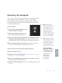
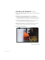
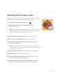
Checking the dewpoint . . . . . . . . . . . . . . . . . . . . . . . . . . . . . . . . . . 5-3
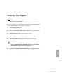
Cleaning the hopper . . . . . . . . . . . . . . . . . . . . . . . . . . . . . . . . . . . . 5-5
Cleaning the process filter. . . . . . . . . . . . . . . . . . . . . . . . . . . . . . . . 5-6
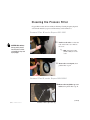
Cleaning the regeneration filter . . . . . . . . . . . . . . . . . . . . . . . . . . . . 5-8
Cleaning the aftercooler/intercooler coils. . . . . . . . . . . . . . . . . . . . . 5-9
Cleaning the precooler coils (W600-1000). . . . . . . . . . . . . . . . . . . 5-11
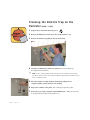
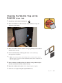
Cleaning the volatile trap on the demister . . . . . . . . . . . . . . . . . . . 5-11
Inspecting hoses and gaskets . . . . . . . . . . . . . . . . . . . . . . . . . . . . 5-11
6-1 Tr o u b l e s h o o t i n g
Before beginning. . . . . . . . . . . . . . . . . . . . . . . . . . . . . . . . . . . . . . . 6-2
A few words of caution . . . . . . . . . . . . . . . . . . . . . . . . . . . . . . . . . 6-3
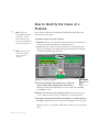
DIAGNOSTICS
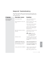
How to identify the cause of a problem . . . . . . . . . . . . . . . . . . . . . 6-4
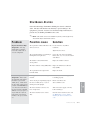
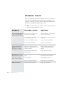
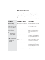
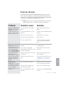
Shutdown alarms . . . . . . . . . . . . . . . . . . . . . . . . . . . . . . . . . . . . . 6-5
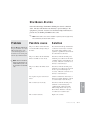
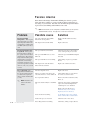
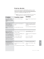
Passive alarms . . . . . . . . . . . . . . . . . . . . . . . . . . . . . . . . . . . . . . . 6-9
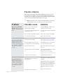
Dewpoint troubleshooting . . . . . . . . . . . . . . . . . . . . . . . . . . . . . . . 6-15
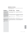
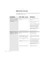
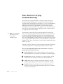
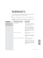
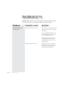
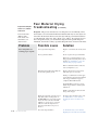
Poor material drying troubleshooting. . . . . . . . . . . . . . . . . . . . . . . 6-16
REPAIR
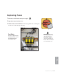
Replacing fuses. . . . . . . . . . . . . . . . . . . . . . . . . . . . . . . . . . . . . . . 6-21
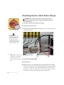
Checking heater solid state relays. . . . . . . . . . . . . . . . . . . . . . . . . 6-22
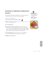
Checking or replacing temperature sensors . . . . . . . . . . . . . . . . . 6-23
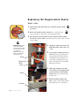
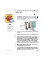
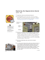
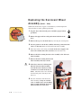
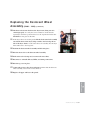
Replacing the regeneration heater (W600-1000). . . . . . . . . . . . . . 6-24
Replacing the regeneration heater (W1600-2400). . . . . . . . . . . . . 6-26
Replacing the regeneration heater (W3200-5000). . . . . . . . . . . . . 6-28
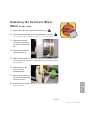
Replacing the desiccant wheel assembly (W600-1000). . . . . . . . . 6-30
Replacing the desiccant wheel motor (W600-1000) . . . . . . . . . . . 6-32
Replacing the desiccant wheel motor (W600-1000) . . . . . . . . . . . 6-33
Ta b l e o f C o n t e n t s l i i i
A
Appendix
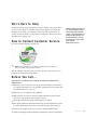
We’re here to help . . . . . . . . . . . . . . . . . . . . . . . . . . . . . . . . . . . . . A-1
How to contact customer service . . . . . . . . . . . . . . . . . . . . . . . . . . A-1
Before you call... . . . . . . . . . . . . . . . . . . . . . . . . . . . . . . . . . . . . . . A-1
Equipment guarantee . . . . . . . . . . . . . . . . . . . . . . . . . . . . . . . . . . A-2
Performance warranty . . . . . . . . . . . . . . . . . . . . . . . . . . . . . . . . . . A-2
Warranty limitations . . . . . . . . . . . . . . . . . . . . . . . . . . . . . . . . . . . . A-2
B
Appendix
Cleaning the precooler coils (W600-1000) . . . . . . . . . . . . . . . . . . . B-1
C
Appendix
Cleaning the volatile trap on the demister (W600-1000) . . . . . . . . . C-1
Cleaning the volatile trap on the demister (W1600-5000) . . . . . . . . C-2
Addendum
Communication protocols for common controls - DC-2
i v l Ta b l e o f C o n t e n t s
SECTION
1
Purpose of the user guide . . . . . . . . . . . . . . 1-2
How the guide is organized . . . . . . . . . . . . . 1-2
Using the Carousel Plus W Series
as a central dryer . . . . . . . . . . . . . . . . 1-3
Yo u r r e s p o n s i b i l i t i e s a s a u s e r . . . . . . . . . . . 1 - 3
AT T E N T I O N :
Read this so no one gets hurt . . . . . . . . 1-4
How to use the lockout device . . . . . . . . . . . 1-6
Introduction l 1-1
1
Introduction
Introduction
Purpose of the User Guide
This User Guide describes the Conair Carousel Plus W Series Dryer and
explains step-by-step how to install, operate, maintain, and repair this
equipment.
Before installing this product, please take a few moments to read the User
Guide and review the diagrams and safety information in the instruction
packet. You also should review manuals covering associated equipment in
your system. This review won’t take long, and it could save you valuable
installation and operating time later.
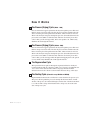
How the Guide is Organized
Symbols have been used to help organize the User Guide and call your
attention to important information regarding safe installation and operation.
Symbols within triangles warn of conditions that could be hazardous to users or
could damage equipment. Read and take precautions before proceeding.
1
Numbers indicate tasks or steps to be performed by the user.
◆
A diamond indicates the equipment’s response to an action performed by the user.
❒
An open box marks items in a checklist.
•
A circle marks items in a list.
✒
✐
1-2 l Introduction
Indicates a tip. A tip is used to provide you with a suggestion that will help you with
the maintenance and the operation of this equipment.
Indicates a note. A note is used to provide additional information about the steps
you are following throughout the manual.
Using the Carousel Plus W Series
as a Central Dryer
Yo u r R e s p o n s i b i l i t y a s a U s e r
You must be familiar with all safety procedures concerning installation, operation and maintenance of this equipment. Responsible safety procedures include:
• Thorough review of this User Guide, paying particular attention
to hazard warnings, appendices and related diagrams.
• Thorough review of the equipment itself, with careful attention
to voltage sources, intended use and warning labels.
• Thorough review of instruction manuals for associated equipment.
• Step-by-step adherence to instructions outlined in this User Guide.
Introduction l 1-3
1
Introduction
The Conair Carousel Plus W600 - 5000 Series Dryers are factory configured to
be used as central dryers only. Therefore, this manual incorporates the information necessary to use these dryers for central drying applications.
AT T E N T I O N :
Read this so no one gets hurt
We design equipment with the user’s safety in mind. You can avoid the potential
hazards identified on this machine by following the procedures outlined below and
elsewhere in the User Guide.
WA R N I N G : I m p r o p e r i n s t a l l a t i o n , o p e r a t i o n , o r
servicing may result in equipment damage or
p e r s o n a l i n j u r y.
This equipment should be installed, adjusted, and serviced by qualified
technical personnel who are familiar with the construction, operation,
and potential hazards of this type of machine.
All wiring, disconnects, and fuses should be installed by qualified electrical technicians in accordance with electrical codes in your region.
Always maintain a safe ground. Do not operate the equipment at power
levels other than what is specified on the machine serial tag and data
plate.
WA R N I N G : Vo l t a g e h a z a r d
This equipment is powered by three-phase alternating current,
as specified on the machine serial tag and data plate.
A properly sized conductive ground wire from the incoming power
supply must be connected to the chassis ground terminal inside the
electrical enclosure. Improper grounding can result in severe personal
injury and erratic machine operation.
Always disconnect and lock out the incoming main power source before
opening the electrical enclosure or performing non-standard operating
procedures, such as routine maintenance. Only qualified personnel
should perform troubleshooting procedures that require access to the
electrical enclosure while power is on.
(continued)
1-4 l Introduction
AT T E N T I O N :
Read this so no one gets hurt
(continued)
CA U T I O N : H o t S u r fa c e s .
Always protect yourself from hot surfaces inside the dryer and hopper.
Also exercise caution around exterior surfaces that may become hot
during use. These include the hopper door frame, the exterior of an
uninsulated hopper, the return air hose and the dryer’s process filter
housing and moisture exhaust outlet.
WA R N I N G : D o n o t p l a c e a e r o s o l , c o m p r e s s e d
gas or flammable materials on or near this
equipment.
The hot temperatures associated with the drying process may cause
aerosols or other flammable materials placed on the dryer or hopper to
explode.
Introduction l 1-5
1
Introduction
We design equipment with the user’s safety in mind. You can avoid the potential
hazards identified on this machine by following the procedures outlined below and
elsewhere in the User Guide.
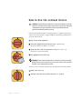
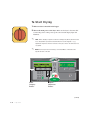
How to Use the Lockout Device
CAUTION: Before performing maintenance or repairs on this product, you should
disconnect and lockout electrical power sources to prevent injury from unexpected
energization or start-up. A lockable device has been provided to isolate this
product from potentially hazardous electricity.
Lockout is the preferred method of isolating machines or equipment from energy
sources. Your Conair product is equipped with the lockout device pictured below.
To use the lockout device:
1 Stop or turn off the equipment.
2 Isolate the equipment from the electric power. Turn the rotary
disconnect switch to the OFF, or “O” position.
3 Secure the device with an assigned lock or tag. Insert a lock or tag
in the holes to prevent movement.
4 The equipment is now locked out.
WARNING: Before removing lockout devices and returning switches to the ON
position, make sure that all personnel are clear of the machine, tools have been
removed, and all safety guards reinstalled.
To restore power to the dryer, turn the rotary disconnect back to the ON position:
1 Remove the lock or tag.
2 Turn the rotary disconnect switch to the ON or “I” position.
1-6 l Introduction
SECTION
2
What is the Carousel Plus W Series Dryer? . . 2-2
Ty p i c a l a p p l i c a t i o n s . . . . . . . . . . . . . . . . . . 2 - 2
How it works . . . . . . . . . . . . . . . . . . . . . . 2-4
Specifications: Carousel Plus W Series
Dehumidifying Dryers . . . . . . . . . . . . . . 2-7
Carousel Plus W Series Dehumidifying
Dryer options . . . . . . . . . . . . . . . . . . . 2-8
Description l 2-1
2
Description
Description
What is the Carousel Plus W Series
Dryer?
The Carousel Plus W Series Dehumidifying Dryer produces low-dewpoint air that
removes moisture from hygroscopic plastics. The dryer pulls moist air from a
drying hopper and circulates it through a dehumidifying desiccant wheel. The
dryer then circulates the air through the material in the hopper.
The dryer’s closed-loop design ensures a continuous supply of dehumidified air
while preventing contamination from moisture in the plant.
Ty p i c a l A p p l i c a t i o n s
1 Dryer on the floor, single hopper (with HTC Hopper Temperature Control
✐
package) on a floor stand.
NOTE: The W600 - 5000 provides no heat to the process
2 Dryer on the floor, multiple hoppers in central configuration (ResinWorks) with
separate heat source for each hopper.
air. A separate heat source is
required at the hopper(s) inlet
to heat the air to the desired
The Carousel Plus W Series Dryer can be used successfully in applications that
require:
drying temperature.
• A contamination-free drying environment.
• A constant flow of dehumidified air.
(continued)
2-2 l Description
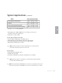
Ty p i c a l A p p l i c a t i o n s
Model
(continued)
Drying Temperature Range
100° - 150°F {38° - 66°C}
Standard
150° - 240°F {66° - 116°C}
High heat (with aftercooler/intercooler)*
150° - 375°F {66° - 191°C}
Low-high (aftercooler/intercooler & precooler)*
100° - 375°F {38° - 191°C}
* See page 3-17, 3-18 and Appendix B
• Throughput rates of 600 to 5000 lbs {271 to 454 kg} per hour (some
materials can be ran at a higher rate).
• Dewpoints of -40°F {-40°C}.
Use the aftercooler/intercooler when:
• You are drying at temperatures over 240°F {116°C}.
• Throughput rates are less than 50% of the dryer’s rated capacity.
• You are pre-drying material at temperatures over 150°F {66°C}
• The return air is 120°F {49°C} or above.
✐
NOTE: The aftercooler/intercooler reduces the temperature of air returning from the
drying hopper, improving the efficiency of the desiccant.
Dryer Features
• Dewpoint monitor/dewpoint control
• Audible and visual alarm
• DeviceNet communications (Alternate communications are available)
✐
NOTE: Temperature setback is only available in conjunction with the Hopper Temperature
Controller (HTC) or ResinWorks system.
✐
NOTE: Carousel Plus W Series 600-1000 Dryers use an aftercooler located before the the process
blower. Carousel Plus W Series 1600-5000 uses an intercooler located after the process blower.
Description l 2-3
2
Description
Low temperature (with precooler)*
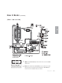
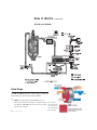
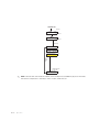
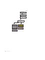
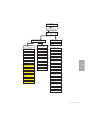
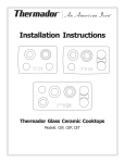
H o w I t Wo r k s
The Process (Drying) Cycle (W600 - 1000)
Process air from the hopper is pulled into the dryer, through the process filter and
then into the process blower inlet. Air exits the process blower and then enters the
aftercooler, then passes through the desiccant wheel, where moisture is removed.
The air exits the dryer and passes through the precooler (if installed), then into the
process heat source (HTC or CGT Gas Unit). After the air exits the process heat
source it then goes into the hopper inlet, then to the spreader cone, which evenly
distributes the air through the material.
The Process (Drying) Cycle (W1600 - 5000)
Process air from the hopper is pulled into the dryer, through the process filter and
then into the process blower inlet. Air exits the process blower and then enters the
intercooler, then passes through the desiccant wheel, where moisture is removed.
The air exits the dryer and passes through the precooler (if installed), then into the
process heat source (HTC or CGT Gas Unit). After the air exits the process heat
source it then goes into the hopper inlet through internal piping, then to the spreader cone, which evenly distributes the air through the material.
The Regeneration Cycle
The regeneration blower pulls air through the regeneration filter into the dryer’s
regeneration heater. The air is heated to 350°F {177°C} before it is pushed into the
“wet” section of the desiccant wheel. The hot air purges moisture from the
desiccant. The moist air is blown out the moisture exhaust at the top of the dryer.
The Cooling Cycle (All models except W2400 and W5000)
Regenerated desiccant must be cooled before it rotates back into the process cycle.
The process blower pushes the process air through the desiccant wheel. A small
amount of the process air is diverted through a small section of the desiccant wheel
to cool the air. The cooling air then returns back to the process air stream at the
start of the process cycle.
2-4 l Description
H o w I t Wo r k s
(continued)
(W600 - 1600 and 3200)
NOTE: Earlier W1600-5000 dryers will have their intercoolers in the W6001000 location.
******
******
**********************
W-series 1600-5000
intercooler location only.
**********************
✐
NOTE: Carousel Plus W Series 600-1000 Dryers use an aftercooler located
before the the process blower. Carousel Plus W Series 1600-5000 dryers
use an intercooler located after the process blower.
Description l 2-5
2
Description
✐
W-series 600-1000
aftercooler location.
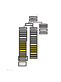
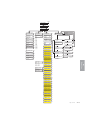
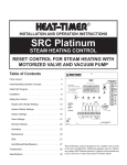
H o w I t Wo r k s
(continued)
(W2400 and W5000)
Power Purge
W 2400 and 5000 models have a Power Purge (cooling fan)
feature integral to the desiccant wheel assembly.
✐
NOTE: Carousel Plus W Series 600-1000 Dryers use an
aftercooler located before the the process blower. Carousel
Plus W Series 1600-5000 dryers use an intercooler located
after the process blower.
2-6 l Description
Protected under
United States Patent
No. 7,101,414 and
other US and Foreign
Patents Pending.
.
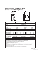
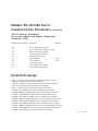
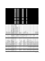
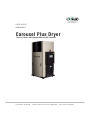
Specifications: Carousel Plus W
Series Dehumidifying Dryers
A
B
C
MODELS
W600*
Performance characteristics (with full hopper)
Drying temperature
Dewpoint
Dimensions inches {cm}
A - Height
B - Width
C - Depth
Outlet/inlet hose diameter
Approximate weight lbs {kg}
Installed
1300 {590}
Shipping
1495 {678}
Voltage - Total amps
400 V/3 phase/50 Hz†
37.2
460 V/3 phase/60 Hz
32.0
575 V/3 phase/60 Hz
25.6
W800*
W1000*
W1600*††
W2400*††
W3200*††
W5000*††
All models 100 - 375°F {38 - 191°C} with options
All models -40°F {-40°C}
92.6 {235.2}
43.3 {109.9}
57.6 {146.3}
8 {20.3}
95.5 {242.6}
48.3 {122.7}
86.2 {218.9}
12 {30.5}
102.8 {261.1}
48.9 {124.2}
112.0 {284.5}
12 {30.5}
1300 {590}
1515 {687}
1400 {636}
1515 {687}
1600 {726}
2100 {953}
1600 {726}
2620 {1188}
2000 {907}
3385 {1535}
2000 {907}
3385 {1535}
37.2
32.0
25.6
37.5
32.2
25.7
64.7
56.3
45.0
73.7
63.1
50.5
122.3
106.6
85.3
128.0
111.0
89.1
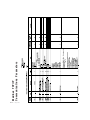
Water requirements {for aftercooler/intercooler or optional precooler}§
Recommended temperature**
Water flow gal./min. {liters/min.}
Water connections NPT
6-25 {22.7-94.6}
45° - 85°F {7- 29}
12-40 {45.4-151.4}
1 1/2 in. NPT
15-50 {56.8-189.3}
SPECIFICATION NOTES:
*
Dryers W600-W5000 are central dryers and do not have process heaters. Hopper Temperature Controllers (HTC’s) or ResinWorks systems are used at the
hopper for heating the process air. See the Hopper Temperature Controller (HTC) specification sheet for additional information.
†
Dryers running at 50 Hz will have 17% less airflow, and a 17% reduction in material throughput.
‡
Total kW listed at a regeneration temperature of 350°F {177°C}.
§
When drying below 150 °F {66°C} a precooler is required. When drying above 180°F {82°C} an aftercooler/intercooler and insulated drying hose is
required.
**
††
Temperatures above or below the recommended levels may affect dryer performance. Tower, chiller or municipal water sources can be used.
Models W1600-5000 do not have casters.
Specifications may change without notice. Consult a Conair representative for the most current information.
TPDS019-0311-REV
Description l 2-7
Carousel Plus W Series
Dehumidifying Dryer Options
• Volatile trap (only in conjunction with aftercooler/intercooler) - The volatile
trap is recommended if drying materials that produce volatile that condense into
a waxy or oily residue and/or if the material contains excessive fines.
• Precooler - The precooler reduces the temperature of air after the desiccant
wheel and before the process heater, which enables the dryer to control
temperatures at low setpoints, (100º - 150ºF {38º - 66ºC})
• Filter check - The filter check sensor will activate a passive alarm when the
process filter is clogged or needs to be replaced.
• CFM monitor - The CFM monitor measures the cubic feet per minute of air
flow across the inlet/outlet of the process blower.
• Communications - Allows the dryer to be networked to industrial control
systems. DeviceNet is standard. Modbus, SPI and Ethernet are available.
• Heater current monitor - The heater current monitor measures the total
amperage across both the process and regeneration heaters and the
pre-determined power consumption values for the blowers and the control.
✐
NOTE: Temperature setback is only available in conjunction with the Hopper Temperature
Controller (HTC) or the ResinWorks system.
✐
NOTE: The Drying Monitor 2 (DM-II) is for use with single hopper applications, it is not
applicable on ResinWorks systems.
2-8 l Description
SECTION
3
Installation
. . 3-2
. . 3-3
. . 3-4
. . 3-4
. . 3-4
. . 3-5
. . 3-6
.
.
.
.
3-7
3-8
3-9
3-9
. 3-12
.
.
.
.
.
3-13
3-14
3-15
3-15
3-16
. 3-17
.
.
.
.
3-18
3-19
3-19
3-20
Installation l 3-1
3
.
.
.
.
Installation
Unpacking the boxes . . . . . . . . . . . . . . .
Preparing for installation . . . . . . . . . . . .
Po s i t i o n i n g t h e d r y e r o n t h e f l o o r . . . . . . .
Removing the cable tie from the
desiccant wheel (W600-1000) . . . . . .
Installing the regeneration exhaust cover .
Installing the return air adapter. . . . . . . .
Installing the return air inlet and air outlet
adapters (W1600-5000) . . . . . . . . . .
Installing the overhead process air duct
(W3200-5000) . . . . . . . . . . . . . . . . .
Connecting the main power . . . . . . . . . . .
Opening the dryer doors (W1600-5000) . . .
Checking for proper air flow . . . . . . . . . .
Connecting the air hoses to a single
hopper (W600-1000) . . . . . . . . . . . . .
Connecting the air hoses to a single
hopper (W1600-5000) . . . . . . . . . . . .
C o n n e c t i n g t h e a i r h o s e s t o a R e s i n Wo r k s .
Connecting the dryer to the hopper . . . . .
C o n n e c t i n g t h e d r y e r t o R e s i n Wo r k s . . . . .
Connecting air hose adapters . . . . . . . . .
Connecting the aftercooler and optional
precooler (W600-1000) . . . . . . . . . . .
Connecting the intercooler and optional
precooler (W1600-5000) . . . . . . . . . .
Mounting a loader on the hopper . . . . . . .
Te s t i n g t h e i n s t a l l a t i o n . . . . . . . . . . . . . .
Using communications . . . . . . . . . . . . . .
Unpacking the Boxes
The Carousel Plus W Series Dryer comes in one to four boxes, depending on the
model and options ordered. The boxes could include (depending on the options
selected):
• Carousel Plus W Series Dryer
• Delivery air hose
• Return air hose
• User Guide
1 Carefully remove the dryer and components from their shipping containers.
Note that the dryer is secured to its shipping container with metal bands that
pass through the bottom of the dryer frame.
2 Unbolt any additional items secured to the shipping pallet, such as the
regeneration exhaust cover and return air adapter. (Carousel Plus W Series
1600-2400 Dryers will have a dry air delivery adapter. Carousel Plus W Series
3200-5000 Dryers will have a dry air delivery adapter and an overhead process
air duct.)
3 Remove all packing material, protective paper, tape, and plastic.
4 Cut and remove the desiccant wheel tie securing the wheel assembly.
(W600-1000)
5 Carefully inspect all components to make sure no damage occurred during
shipping, and that you have all the necessary hardware.
(continued)
3-2 l Installation
Unpacking the Boxes
(continued)
6 Take a moment to record serial numbers and electrical power specifications
in the blanks provided on the back of the User Guide’s title page. The information will be helpful if you ever need service or parts.
7 You are now ready to begin installation.
Follow the preparation steps on the next page, then choose one of the two
mounting options:
• Dryer on the floor, single hopper (with HTC Hopper Temperature Control
package) on a floor stand.
• Dryer on the floor, multiple hoppers in central configuration (ResinWorks)
with separate heat source for each hopper.
NOTE: The W600 - 5000 provides no heat to the process air. A separate heat source is
required at the hopper(s) inlet to heat the air to the desired drying temperature.
Preparing for Installation
✒
TIP: If you plan to use vacuum or compressed air load-
The Carousel Plus W Series Dryer is easy to install if you plan the location and
prepare the mounting area properly.
ers to fill the hopper, install
conveying lines to the drying
hopper location.
1 Make sure the mounting area provides:
❒ A grounded power source supplying the voltage and correct current
for your dryer model. Check the dryer’s serial tag (on the control box) for
the correct amps, voltage, phase, and cycles. Field wiring should be completed by a qualified personnel to the planned location for the dryer. All
electrical wiring should comply with your region’s electrical codes.
❒ A source of water, when using the aftercooler/intercooler and/or precooler. The W Dryer’s aftercooler/intercooler and/or precooler require
tower, city, or chiller water at temperatures of 45° to 85°F {7° to 29°C}.
Refer to the Specifications Sheet (page 2-7) for flow rate for your unit.
Piping should be ran to the planned dryer location. Use flexible hose to
connect the water pipes to the aftercooler/intercooler and/or optional
precooler.
✐
NOTE: The aftercooler/intercooler reduces the temperature
of air returning from the drying
hopper, improving the efficiency of the desiccant.
❒ Minimum clearance for safe operation and maintenance. You should
maintain 24 in. {61 cm} clearance on all sides of the dryer.
Installation l 3-3
3
Installation
✐
Po s i t i o n i n g t h e D r y e r o n t h e F l o o r
1 Lift the dryer from the shipping container using a fork truck.
2 Position the dryer on the floor near the hopper or ResinWorks sled. Make
sure the location allows for the connection of all hoses, keeping hose lengths as
short as possible.
R e m o v i n g t h e C a b l e Ti e f r o m t h e
D e s i c c a n t W h e e l (W600-1000 models)
1 Open the dryer side panels and remove the cable tie securing the desiccant
✒
Desiccant Cable Tie
wheel, if it was not done while unpacking the dryer.
Installing the Regeneration
Exhaust Cover
The Carousel Plus W Series Dryer’s regeneration exhaust cover must be installed.
To install the regeneration exhaust cover:
1 Remove the exhaust cover that is attached to the dryer’s shipping pallet.
2 Locate the bolt pattern at the top of the dryer, on top of the regeneration
exhaust outlet.
3 Position the regeneration exhaust cover on top of the regeneration exhaust
Regeneration
Exhaust Cover
outlet, aligning both bolt patterns.
4 Secure the regeneration exhaust cover with supplied hardware, using an
appropriately sized wrench.
3-4 l Installation
Installing the Return Air Adapter
The Carousel Plus W Series Dryer’s return air adapter must be installed.
To install the return air adapter:
1 Remove the return air adapter that is attached to the dryer’s shipping
pallet.
2 Locate the bolt pattern on the top of the dryer, on top of the return air inlet.
3 Position the return air adapter on top of the return air inlet, aligning both
bolt patterns.
Return Air
Inlet Adapter
ly sized wrench.
Installation l 3-5
3
Installation
4 Secure the return air adapter with supplied hardware, using an appropriate-
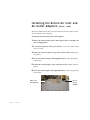
Installing the Return Air Inlet and
A i r O u t l e t A d a p t e r s (W1600 - 5000)
The Carousel Plus W Series Dryer’s return air inlet and air outlet adapters will be
removed when the dryer is shipped
To install the return air inlet and air outlet adapters:
1 Remove the return air inlet and air outlet adapters that are attached to the
dryer’s shipping pallet.
2 Locate the bolt patterns on the top of the dryer, on top of the return air inlet
and air out outlet.
3 Position the return air adapter on top of the return air inlet, aligning both
bolt patterns.
4 Secure the return air adapter with supplied hardware, using appropriately
sized wrench.
5 Position the air inlet adapter on top of the inlet air inlet, aligning both bolt
patterns.
6 Secure the air inlet adapter with supplied hardware, using an appropriately
sized wrench.
Return Air
Inlet Adapter
3-6 l Installation
Dry Air
Outlet
Adapter
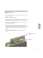
Installing the Overhead Process Air
D u c t (W3200 - 5000)
The Carousel Plus W Series Dryer’s overhead process air duct will be removed
when the dryer is shipped.
To install the overhead process air duct:
1 Remove the overhead process air duct that is attached to the dryer’s shipping pallet. The piping will be shipped as one unit with included gaskets (2).
2 Locate the bolt patterns on the top of the dryer, over top of the overhead
process air duct inlet and outlet.
duct inlet and outlet making sure to place supplied gaskets between the
overhead process air duct and the inlet and outlet of the dryer, align all bolt
patterns.
4 Secure the piping with supplied hardware, using an appropriately sized
wrench.
Overhead Process Air
Duct
Gaskets (2)
Installation l 3-7
3
Installation
3 Position the overhead process air duct on top of the overhead process air
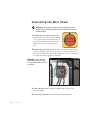
C o n n e c t i n g t h e M a i n Po w e r
CAUTION: Always disconnect and lock out the main power sources before
making electrical connections. Electrical connections should be made only by
qualified personnel.
1 Open the dryer’s electrical enclosure. Turn
the disconnect dial on the dryer door to the Off
or “O” position. Lock out the main power (see
Page 1-6 for complete lock out information).
Turn the captive screw, and swing the door
open.
2 Insert the main power wire through the knockout in the side of the enclosure
or the rear of the dryer. (the dryer’s electrical wire connection location was a
factory option and may be connected through the front or the rear of the dryer.)
Secure the wire with an appropriate strain relief.
IMPORTANT: Always refer to the
wiring diagrams that came with
your dryer before making electrical
connections.
3 Connect the power wires to the three terminals at the top of the power
disconnect holder.
4 Connect the ground wire to the ground lug as shown in the photo.
3-8 l Installation
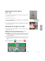
Opening the Dryer Doors
(W1600 - 5000)
Carousel Plus W Series 1600-5000 Dryers designed after August 2007 will have
locking side panel door bolts.
To unlock the side panel door bolts:
1 Rotate the two (2) locking door bolts on the dryer door counterclockwise
with a regular screw driver.
Dryer Door
Locking Bolts (2)
(W1600-5000)
2 Close the dryer doors and rotate the two (2) locking door bolts clockwise
to resecure the dryer doors.
This procedure is needed on W600-5000 models if the phase detection option was
not ordered with the dryer.
IMPORTANT: This procedure must be performed before the dryer’s air hoses are
connected to the hopper or before loading material into the hopper.
CAUTION: If the air flow direction is incorrect due to improper phase connection,
material from the hopper can be pulled back into the dryer, causing permanent
damage to this equipment.
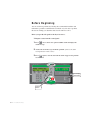
1 Turn on the main power to the dryer. Make sure the dryer’s disconnect dial
is in the ON position. This powers up the control and the display lights will
illuminate.
2 Press the START button
Start
then the STOP button.
Stop
Menu
3
3
Select
Category
Process Blower
Prev
Scroll List
Regen. Blower
Auto Start
Regen. Heater
Dewpoint Control
Next
1
2
3
4
5
6
7
8
9
Clear
0
Adjust Setpoint
Acknowledge
Alarm
Start
Stop
Enter
1000
(continued)
Installation l 3-9
3
Installation
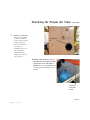
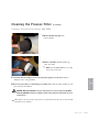
Checking for Proper Air Flow
Checking for Proper Air Flow
✐
(continued)
NOTE: Models W600-1000
dryer aftercooler and dry
air delivery configuration
shown. Location on larger
Dry Delivery
Air
models are different.
Refer to the labeling on
your dryer. See
Installation section entitled, Installing the
Return/Delivery Air
Adapters, for proper air
line connections.
3 Visually verify the blower motor is
moving in the correct direction indicated by the arrow on the blower
housing. The W series 600-5000 dryers
are equipped with centrifugal process
blowers.
Direction
Indication
Arrow
(continued)
3-10 l Installation
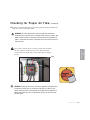
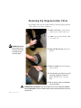
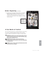
Checking for Proper Air Flow
(continued)
4 If air flow is incorrect disconnect power, follow proper lockout procedures and
swap any 2 of the 3 main power wires.
WARNING: All wiring, disconnects, and fuses should be installed by
qualified electrical technicians in accordance with electrical codes in your
region. Always maintain a safe ground. Do not operate the equipment at
power levels other than what is specified on the the machine serial tag
and data plate.
If the air flow is reversed, the process blower is turning in the wrong direcenclosure and reverse any two leads connecting the main power supply to
the dryer.
LEADS
WARNING: All wiring, disconnects, and fuses should be installed by qualified electrical technicians in accordance with electrical codes in your
region. Always maintain a safe ground. Do not operate the equipment at
power levels other than what is specified on the the machine serial tag
and data plate.
Installation l 3-11
3
Installation
tion. Turn off and lock out the main power source. Open the electrical
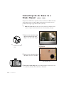
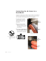
Connecting the Air Hoses to a
S i n g l e H o p p e r (W600 - 1000)
Using the two flexible hoses provided, connect the inlet of the HTC and outlet
of the drying hopper to the dryer. Make sure the dryer is located as close as
possible to the hopper (approximately 10 ft {3.05 m}).
✐
NOTE: Models W600-1000 dryer aftercooler and dry air delivery configuration shown.
Location on larger models are different. Refer to the labeling on your dryer.
1 Attach one hose from the return
air inlet, located on top of the
dryer, to the outlet of the hopper.
✐
NOTE: Do not allow the
Return Air
Inlet Adapter
flexible hoses to kink or
crimp.
2 Attach one hose from the delivery
air outlet to the inlet of the HTC.
Dry Delivery Air
3 Secure hoses with clamps. The hose clamp should be secured at least 1/4
in. {0.64 cm} from the end of the inlet or outlet tube.
3-12 l Installation
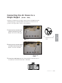
Connecting the Air Hoses to a
S i n g l e H o p p e r (W1600 - 5000)
Using the two flexible hoses provided, connect the inlet of the HTC and outlet
of the drying hopper to the dryer. Make sure the dryer is located as close as
possible to the hopper (10 ft {3.05 m} of hose supplied).
1 Attach one hose from the return
air inlet, located on top of the
dryer, to the outlet of the hopper.
flexible hoses to kink or
Return Air
Inlet
crimp.
2 Attach one hose from the delivery
air outlet, located on top of the
dryer, to the inlet of the HTC.
Delivery Air
Outlet
3 Secure hoses with clamps. The hose clamp should be secured at least 1/4
in. {0.64 cm} from the end of the inlet or outlet tube.
Installation l 3-13
3
NOTE: Do not allow the
Installation
✐
Connecting the Air Hoses to a
R e s i n Wo r k s
Using the two flexible hoses provided, connect the delivery air and return air
manifolds of the ResinWorks to the dryer. Make sure the dryer is located as
close as possible to the sleds (10 ft {3.05 m} of hose supplied).
1 Attach one hose from the
return air inlet of the dryer to
the return air manifold of the
ResinWorks.
Dry
Delivery
Air
2 Attach one hose from the
delivery air outlet of the dryer
to the delivery air manifold of
the ResinWorks.
3 Secure hoses with clamps. The
Return
Air
hose clamp should be secured at
least 1/4 in. {0.64 cm} from the
end of the inlet or outlet tube.
Insulated hose shown not standard.
✐
NOTE: Do not allow the
flexible hoses to kink or
crimp.
Dry
Delivery
Air
Return
Air
3-14 l Installation
Connecting the Dryer to the Hopper
If your dryer hose connection and your hopper HTC hose connection are not the
same size, you will need a hose adapter. Contact Conair Parts 1 800-458-1960.
✐ Connecting the Dryer to
NOTE: Because the W600 - 5000 models require a separate heat source for the
delivery air, all references to this heat source will be identified as “HTC” (Hopper
Temperature Controller). When using this dryer with an HTC, reference the User
Guide supplied with the HTC for installation instructions.
R e s i n Wo r k s
NOTE: Because the W600-5000 models require a separate heat source for the delivery air, all references to this heat source will be identified as ResinWorks. When
using this dryer with a ResinWorks sled reference the User Guide supplied with the
ResinWorks sled for installation instructions.
Installation l 3-15
3
✐
Installation
If your dryer hose connection and the connection on your ResinWorks sled are not
the same size, you will need to use a hose adapter. Contact Conair Parts
1 800-458-1960.
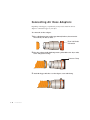
Connecting Air Hose Adapters
Depending on the hopper you purchased you may need to install an air hose
adapter to connect the hopper to your dryer.
To connect the air hose adapter:
1 Place a high temperature gasket approximately half way down from the
end of the dry air delivery outlet.
Dryer Inlet/Outlet
Connection
2 Place hose adapter inside high temperature gasket flush to the dryer outlet,
secure with pressure clamp.
Pressure Clamp
3 Attach the hopper inlet hose over the adapter, secure with clamp.
3-16 l Installation
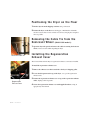
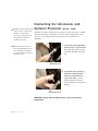
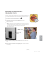
Connecting the Aftercooler and
O p t i o n a l P r e c o o l e r (W600 - 1000)
The aftercooler and/or optional precooler require a source of city, tower, or chiller
water and a discharge or return line. You can use water at temperatures of 45 to
85°F {7 to 29°C}. But the water flow should be at least 3 gal/min {11.4
liters/min}.
✒TIP: Make the water supply and discharge / return connections with
flexible hoses at least 24 in.
(61 cm) long. This allows you to
easily remove the aftercooler
1 Connect the water supply line to
assembly for cleaning.
✒TIP: If an optional flow control is
also being installed with the aftercooler, the manual shut off valve
for the flow control.
Aftercooler Inlet
✐
NOTE: Models W600-1000
dryer aftercooler and dry air
2 Connect the water discharge or
return line with the pressure
relief valve to the aftercooler or
precooler outlet. Use the bracket
supplied to secure the pressure
relief valve to the back of the
dryer.
delivery configuration shown.
Location on larger models
are different. Refer to the
labeling on your dryer.
Aftercooler Outlet
IMPORTANT: Turn the water off when the dryer is not in use to prevent
condensation.
Installation l 3-17
3
should be installed on the inlet line
Installation
the aftercooler or precooler inlet.
If a manual shut off valve is used,
it should be mounted on the inlet
line.
✒TIP: Make the water supply and discharge / return connections with
flexible hoses at least 24 in.
(61 cm) long. This allows you to
easily remove the intercooler
assembly for cleaning.
Connecting the Intercooler and
O p t i o n a l P r e c o o l e r (W1600 - 5000)
The intercooler and/or optional precooler require a source of city, tower, or chiller
water and a discharge or return line. You can use water at temperatures of 45 to
85°F {7 to 29°C}. But the water flow should be at least 3 gal/min {11.4
liters/min}.
1 Connect the water supply line to
✒TIP: If an optional flow control is
the intercooler or precooler inlet.
If a manual shut off valve is used,
it should be mounted on the inlet
line.
also being installed with the intercooler, the manual shut off valve
should be installed on the inlet line
for the flow control.
Intercooler Inlet
2 Connect the water discharge or
return line with the pressure
relief valve to the intercooler
or precooler outlet. Use the
bracket supplied to secure the
pressure relief valve to the back of
the dryer.
Intercooler Outlet
IMPORTANT: Turn the water off when the dryer is not in use to prevent
condensation.
3-18 l Installation
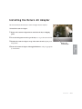
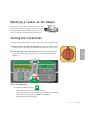
Mounting a Loader on the Hopper
If you have a Conair loader or vacuum receiver, you can
use the flange and mounting clips provided on the top of
the hopper. Refer to the manuals that came with your
receiver or loader for detailed installation instructions.
Te s t i n g t h e I n s t a l l a t i o n
You have completed the installation. Now it’s time to make sure everything works.
1 Make sure there is no material in the hopper. If you have mounted a loader or
vacuum receiver on the hopper, disconnect the material inlet hose at the source.
is in the ON position. This powers up the control and the display lights will
illuminate.
Menu
3
3
Select
Category
Process Blower
Prev
Scroll List
Regen. Blower
Auto Start
Regen. Heater
Dewpoint Control
Next
1
2
3
4
5
6
7
Clear
8
0
Adjust Setpoint
9
Acknowledge
Alarm
Start
Stop
Enter
1000
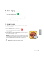
3 Press the START button.
Start
If everything is installed correctly:
• The green light on the start button will illuminate.
• The regeneration and process blowers turn on and LEDs will illuminate.
• The regeneration heater turns on and LED will illuminate.
• The desiccant wheel starts turning
Installation l 3-19
3
Installation
2 Turn on the main power to the dryer. Make sure the dryer’s disconnect dial
Te s t i n g t h e I n s t a l l a t i o n
4 Press the STOP button.
Stop
If everything is installed correctly:
• The blowers will continue running as needed to cool the heaters.
(until regeneration heaters are less than 150°F {66°C})
5 The test is over. If the dryer performed the normal operating sequences as outlined, you can load the hopper and begin operation. If it did not, refer to the
Troubleshooting section of the User Guide.
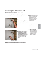
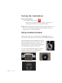
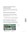
Using Communications
The DeviceNet cable feature is a standard feature on W600-5000 dryers with
DC-2 controls. It allows the dryer to be connected your communications network.
If the communications feature will NOT be used for your
application, simply coil the cable to keep it out of the way.
If the communications feature IS to be used for your
application, please refer to the documentation supplied in
the Communication Addendum of this manual.
To use the optional SPI, Modbus, Ethernet or standard
DeviceNet communications see the Addendum for
hardware installation and configuration.
SPI Connection
3-20 l Installation
Ethernet Connection
DeviceNet Connection
SECTION
4
Operation
Carousel Plus W Series Dryer:
control panel DC-2 . . . . . . . . . . . . . . . 4-2
Carousel Plus W Series Dryer
control functions . . . . . . . . . . . . . . . . 4-3
How to navigate the menu tree . . . . . . . . . . 4-3
Control function descriptions . . . . . . . . . . . 4-11
To s t a r t d r y i n g . . . . . . . . . . . . . . . . . . . . 4 - 3 4
To s t o p d r y i n g . . . . . . . . . . . . . . . . . . . . . 4 - 3 5
H o w t o u s e t h e s u p e r v i s o r ’s p a s s w o r d . . . . . 4 - 3 6
Using the dewpoint monitor and dewpoint
control . . . . . . . . . . . . . . . . . . . . . . . 4-38
Using the auto start timer . . . . . . . . . . . . . 4-39
Operation l 4-1
4
Operation
Control function flow charts . . . . . . . . . . . . 4-3
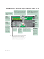
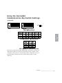
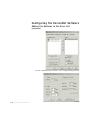
C a r o u s e l P l u s W S e r i e s D r y e r : C o n t r o l Pa n e l D C - 2
S c r e e n Ti t l e
Alpha-numeric characters
display process and alarm
conditions.
Menu Button
Scroll Buttons
Press to view the main menu screen where you can
select on screen categories or press again to return to
the default screen where regeneration temperature
and actual setpoint are displayed. This button can be
pressed at any time to return to the default screen.
Press to scroll through the closed loop parameter
list. The “Prev” button scrolls the user up the
list, while the “Next” button scrolls the user
down the list to the last screen and then back to
the parameter list title screen at the top.
Status
Display
Select
Category
Press to select onscreen categories,
paths and options.
Menu
3
3
Select
Category
Process Blower
Prev
Scroll List
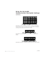
Numeric
Keypad
1
2
3
4
5
6
7
Clear
8
0
9
Adjust Setpoint
Dewpoint Control
Acknowledge
Alarm
Start
Stop
Enter
Clear Button
1000
Press to clear highlighted on-screen
data entry fields,
only after data has
been entered.
The clear button
clears the field one
number at a time.
Enter Button
Used to lock-in
data entries.
Increment/
Decrement
Buttons
Used to increase
or decrease
values.
✐
l Operation
Auto Start
Next
Press numbers to
enter data.
4-2
Regen. Blower
Regen. Heater
Alpha-numeric
characters display process
and alarm conditions.
Start and Stop Buttons
Press “Start” to start the dryer.
Press “Stop” to stop the dryer.
NOTE: When changing a setpoint use the Select Category
Key directly below the value to be changed. Once
pressed the value will blink, then use the keypads or (+)
(-) adjustment setpoints to enter the new value. Then
press enter for the new value to be recognized.
Dryer
Status
Illuminated
lights show
the status of
the dryer.
Acknowledge
Alarm Button
Press once to
silence the optional audible alarm
and display alarm
messages. Press
again to clear the
alarm.
Carousel Plus W Series Dryer
Control Functions
Dryer functions are values that you can set or monitor in the Screen Title and
Status Display windows. Press the Menu button then the Scroll List “Next” or
“Prev” buttons until the function you want to set or monitor appears in the Screen
Title window.
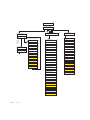
Control Function Flow Charts
The charts beginning on page 4-4 provide a quick summary of the control
functions. For an explanation of each control function, see Control Function
Descriptions (page 4-11). The screen numbers correspond with the numbers
beside each block in the flow chart.
✐
NOTE: In the flow charts of the display screens that follow this page, the grey shaded
screens denote optional functions. If the options were not purchased with the dryer,
those screens will not appear. Most options can be purchased and installed in the field.
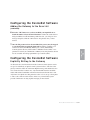
To scroll through main menu, use scroll buttons (“Next”, “Previous”). Push
“Menu” to access Dryer Main Menu . To access the Status, Setup, Diagnostic and
Password screens, use the select category buttons under the digital read-out and
then the scroll buttons (“Next”, “Previous”) to scroll through the parameter lists.
Menu Button
Menu
3
3
Select
Category
Process Blower
Prev
Scroll List
Regen. Blower
Auto Start
Regen. Heater
Dewpoint Control
Next
1
2
3
4
5
6
7
8
9
Clear
0
Adjust Setpoint
Acknowledge
Alarm
Start
Stop
Enter
1000
Select Category Buttons
Scroll Buttons
Operation l 4-3
4
Operation
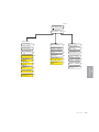
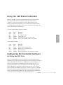
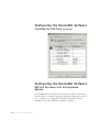
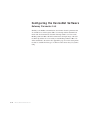
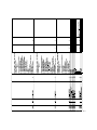
H o w t o N a v i g a t e t h e M e n u Tr e e
POWER ON
Screen #
CONAIR
CV00.06.2
CP600
DV00.09.8
1
3 SEC DELAY
MONDAY
7/22/2003
07:59 AM
2
3 SEC DELAY
Central Dryer
REGENERATION TEMP
ACT 350˚F
SET 350˚F
4
RETURN AIR TEMP
ACT 120˚F
SET 120˚F
5
PROCESS DEWPOINT
ACT -47˚F
SET -40˚F
11
PRESS
MENU
KEY
✐
4-4
PRESS MENU KEY
AT ANY TIME
DRYER MAIN MENU
STAT SETUP DIAG 12
NOTE: In the event new control boards are installed, screens showing Process and MDC may be present. The boards
will need to be configured for a central dryer. If this is not done, alarms will occur.
l Operation
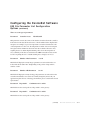
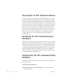
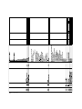
Screen #
DRYER MAIN MENU
STAT SETUP DIAG
12
DRYER STATUS
PROC REGEN
OTHER
13
CENTRAL DRYER
DRYER PROCESS
STATUS SCREENS
14
DRYER REGEN
STATUS SCREENS
14
DRYER OTHER
STATUS SCREENS
14
RETURN AIR TEMP
ACT 120˚F SET 120˚F
5
REGENERATION TEMP
ACT 350˚F
SET 350˚F
4
MODEL 5000
480 V
60 HZ
30
TOTAL RUN HOURS
1250
17
REGEN OUTLET TEMP
ACT 280
29
DISPLAY FIRM V2.21.00
31
DISPLAY MENU V2.21.00
PROCESS CFM 1600
20
REGEN HEATER
OUTPUT 68%
15
CONTROL FIRMWARE
VERSION
V2.21.00
AFTERCOOLER
ENABLED
DISABLED
AFTERCOOLER
FLOW OFF
FLOW ON
21
REGEN CURRENT
14.3A 14.4A 14.2A
22
AUTOSTART COUNT DOWN
REGEN POWER
20 KWH
23
AUTOSTOP COUNT DOWN
21
PROCESS DEWPOINT
ACT -40˚F SET -100˚F
11
PROCESS DEWPOINT
AVERAGE -55˚F
24
11:04:23
PANEL INSIDE TEMP
ACT 100˚F
33
34
35
Operation l 4-5
4
23
3 DAYS
23:05:53
Operation
TOTAL POWER
80 KWH
1 DAYS
32
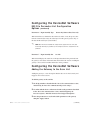
SCREEN #
DRYER MAIN MENU
STAT SETUP DIAG
12
DRYER SETUP
PROC ALM DISP OTHER
36
SETUP PROCESS
PROC
REGN
OTHER
37
CENTRAL DRYER
SETUP PROCESS
PROC
RETPID
14
SETUP AFTERCOOLER
14
on off VALUE SCREENS
RETURN AIR TEMP
ACT 120˚F SET 120˚F
5
RET AIR CYCLE TIME
COOL 20 SECONDS
42
AFTERCOOLER
Enabled
Edit
Disabled
21
RET AIR CALIBRATION
OFFSET 2˚F
47
PROCESS DEWPOINT
ACT -40˚F SET-40˚F
11
SETUP PROCESS
SCREENS
4-6
l Operation
38
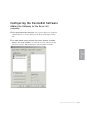
Screen #
SETUP REGENERATION
REGEN
PID
SETUP REGENERATION
SCREENS
14
DRYER MAIN MENU
STAT SETUP DIAG
12
DRYER SETUP
PROC ALM DISP OTHER
36
SETUP PROCESS
PROC REGEN
OTHER
37
SETUP PROCESS
OTHER SCREENS
48
SETUP REGEN HEATER
PID VALUE SCREENS
14
REGEN POWER LIMIT
LOW 0% HIGH 100%
41
REGEN OUTLET TEMP
ACT 280
29
REGEN CYCLE TIME
2.0 SEC
42
REGEN TEMP
RANGE 100˚F - 375˚F
39
REGEN PROBAND
67F
43
REGEN PID
AUTOTUNE OFF
40
REGEN INTERGRAL
25
44
REGEN CALIBRATION
OFFSET 0˚F
47
REGEN DERIVATIVE
4
45
OPT
PROCESS DEWPOINT
SAMPLE RATE
150 SEC
49
REGEN PID RESET
HEAT
46
OPT
PROCESS DEWPOINT
TRIM UP LIMIT
375˚F
50
REGEN CALIBRATION
OFFSET 0˚F
47
OPT
PROCESS DEWPOINT
TRIM LOW LIMIT
100F
51
OPT
PROCESS DEWPOINT
GAIN
0.7
52
DONE
PROCESS DEWPOINT
OPT DEAD BAND
1
OPT
PROCESS DEWPOINT
CONTROL
RESET
53
54
MONDAY START TIME
ON 8:00 AM
56
MONDAY STOP TIME
OFF 8:00 PM
57
TUESDAY START TIME
ON
8:00 AM
56
TUESDAY STOP TIME
OFF
8:00 PM
57
WEDNESDAY START TIME
ON
8:00 AM
56
WEDNESDAY STOP TIME
OFF 6:00 PM
57
THURSDAY START TIME
ON 8:00 AM
56
THURSDAY STOP TIME
OFF
6:00 PM
57
FRIDAY START TIME
ON
8:00 AM
56
FRIDAY STOP TIME
OFF 8:00 PM
57
SATURDAY START TIME
ON
8:00 AM
56
SATURDAY STOP TIME
OFF
8:00 PM
57
SUNDAY START TIME
ON
8:00 AM
56
SUNDAY STOP TIME
OFF
8:00 PM
57
Operation l 4-7
4
4
55
Operation
REGENERATION TEMP
ACT 350˚F SET 350˚F
AUTOSTART TIMER
ENABLED
EDIT
DISABLED
14
Screen #
ALARM
ACTION
DRYER SETUP ALARM
ACTION SCREENS
l Operation
12
DRYER SETUP
PROC ALM DISP OTHER
36
ALARM
SETUP
58
DRYER SETUP CONTROL
DISPLAY SCREENS
14
UNITS
STANDARD
METRIC
71
14
DRYER SETUP ALARM
SETPOINT SCREENS
14
REGN TEMP LOOP BREAK
ON EDIT PASS EDIT
59
REGEN HIGH TEMP
400˚F
5 SEC
60
TIME DISPLAY
12 HOUR
24 HOUR
REGN TEMP DEVIATION
ON EDIT PASS EDIT
59
REGEN LOW TEMP
200˚F
5 SEC
60
DATE
5/23/2002
REGN HIGH TEMP ALARM
ON EDIT PASS EDIT
59
REGEN LOOP BREAK
2˚F
40 SEC
61
REGEN LOW TEMP ALARM
ON EDIT PASS EDIT
59
REGEN TEMP DEV
10˚F
5 SEC
62
RET MID-HI TEMP ALRM
ON EDIT PASS EDIT
59
REGEN DIFFERENTIAL
20˚F
10 SEC
63
PROC DEWPOINT ALARM
ON EDIT PASS EDIT
59
REGEN DIFFERENTIAL
TIME DELAY
5 MIN
64
FILTER CHECK ALARM
ON EDIT PASS EDIT
59
RETURN AIR ALARMS
PASS 125˚F SHUT 180˚F
65
LOW CFM ALARM
ON EDIT PASS
EDIT
59
RETURN AIR LOOP BRK
3˚F
20 SEC
61
DEWPOINT DEV HIGH
ON EDIT PASS EDIT
59
CFM LOW SETPOINT
1
66
DEWPOINT DEV LOW
ON EDIT PASS EDIT
59
DEWPOINT ALARM
ACT -20F
180 SEC
67
WHEEL ROTATION
ON EDIT PASS
59
DEWPOINT DEVIATION
HIGH
5˚F
30 sec
68
REGEN BLOWER OVRLOAD
ON EDIT PASS EDIT
59
DEWPOINT DEVIATION
5˚F
30 sec
LOW
69
MACHINE LOADER ALRM
ON EDIT PASS EDIT
59
DEWPOINT
TIME DELAY
70
HOPPER LOADER ALRM
ON EDIT PASS EDIT
59
EDIT
These screens are
visible but not
functional.
4-8
DRYER MAIN MENU
STAT SETUP DIAG
5 MIN
EDIT
TIME
Mon 10:33 AM
72
73
Screen #
DRYER SETUP OPTIONS
INFORMATION SCREENS
14
DRYER MAIN MENU
STAT SETUP DIAG
12
DRYER SETUP
PROC ALM DISP OTHER
36
DRYER SETUP OTHER
OPT INSP COM PW
74
DRYER SETUP MODEL
CONFIG SCREENS
14
DRYER SETUP
COMMUNICATIONS
14
Dryer Setup
Password Screen
14
Logging Out
Password …
IF A VALID PASSWORD IS STILL ACTIVE
CFM MONITOR
NOT INSTALLED
FILTER CHECK
INSTALLED
EDIT
EDIT
75
75
AFTERCOOLERFLOW CONT
INSTALLED
EDIT 75
PRECOOLER
INSTALLED
EDIT
75
REGEN CURRENT TRANS
INSTALLED
EDIT
75
REGEN CURRENT TAP
5A
76
10A
15A
RGN CURRENT SCALE
1
77
DEWPOINT MONITOR
INSTALLED
EDIT
75
DEWPOINT CONTROL
INSTALLED
EDIT
PHASE ROTATION
INSTALLED
EDIT
MODEL NUMBER
CP150
EDIT
78
CP15
CP25
CP50
CP75
CP100
CP150
CP200
CP300
CP400
CP600
CP800
CP1000
CP1600
CP2400
CP3200
CP5000
PROTOCOL
MODBUS
EDIT
SLAVE ID
1
BAUD RATE
19200
PARITY
NONE
EVEN
ODD
81
82
EDIT
EDIT
MAP INDIRECT REG 500
0
83
84
Enter Password
XXXX
Invalid Password
85
85
87
Valid Supervisor
Password Entered
Logout Supervisor
Password
No
IF 2ND AND 4TH
SEL KEYS ARE PRESSED
Change Supervisor
Password
Yes
102
88
89
Reset Password
MAP INDIRECT REG 501
94
102
MAP INDIRECT REG 502
3
102
IF CORRECT
86
Enter New Password
90
Enter New Password
1111
90
86
75
75
EDIT
80
Display Firm V9.72.95
Display Menu V2.01.00
31
Control Firmware
Version V2.01.00
32
MAP INDIRECT REG 504
8
102
MAP INDIRECT REG 505
77
102
MAP INDIRECT REG 506
4
102
MAP INDIRECT REG 507
11
102
MAP INDIRECT REG 508
40
102
MAP INDIRECT REG 509
41
102
MAP INDIRECT REG 510
6
102
MAP INDIRECT REG 511
42
102
MAP INDIRECT REG 512
43
102
MAP INDIRECT REG 513
78
102
MAP INDIRECT REG 514
79
102
MAP INDIRECT REG 515
100
102
MAP INDIRECT REG 516
153
102
MAP INDIRECT REG 517
10
102
MAP INDIRECT REG 518
0
102
MAP INDIRECT REG 519
0
102
MAP INDIRECT REG 530
94
102
MAP INDIRECT REG 531
82
102
MAP INDIRECT REG 532
77
102
MAP INDIRECT REG 533
78
102
MAP INDIRECT REG 534
66
102
MAP INDIRECT REG 535
306
102
MAP INDIRECT REG 536
307
102
MAP INDIRECT REG 537
309
102
Supervisor Password
Reset to Default
3 Sec.
IF INCORRECT
86
Unknown Password
New Supervisor Pw Is
90
1111
APPEARS FOR
3 SECONDS
APPEARS FOR
3 SECONDS
Operation l 4-9
4
FREQ
60 HZ
60 Hz
60 HZ
50 HZ
60 HZ
60 HZ
102
Operation
Voltage
208V
208V
240V
400V
460V
575V
MAP INDIRECT REG 503
82
Screen #
DRYER MAIN MENU
STAT SETUP DIAG
Dryer Diagnostic
ALRM
HIST
12
I/O
91
NA
KEEP 40 SHOWN
DRYER DIAGNOSTICS
LAST 40 ALARMS
00:S-Regen RTD
01/31/00 09:24 P
DIAGNOSTIC EVENTS
ALRMS ANALOG DIGITAL
14
94
92
Alarm Activated For
10.3 Minutes
DOWN
OR UP
ARROW
KEY
02:P-REGEN DEV
3/1/00 03:25P
RETURN AIR TEMP
ACT 120˚F SET 120˚F
INFO
INFO
92
92
REGENERATION TEMP
ACT 425˚F SET 425˚F
REGEN OUTLET TEMP
ACT 280
REGEN HEATER
OUTPUT 68%
ETC.
PROCESS CFM 1500
FILTER CHECK
PRES SWT CLOSED
PROCESS DEWPOINT
ACT -40F SET -100F
AFTERCOOLER
FLOW ON
PRECOOLER
FLOW OFF
93
DRYER DIAGNOSTICS
EVENT FREQ SCREENS
93
REGEN HIGH TEMP
S-0
P-0
93
93
l Operation
14
DRYER DIAGNOSTIC
DIGITAL I/O
14
START DIGITAL I/O
DIAGNOSTICS
OFF
97
PROCESS BLOWER
ON
OFF
JOG
98
REGEN BLOWER
ON
OFF
JOG
98
REGEN HEATER
98
95
REGEN LOOP BREAK
S-0
P-0
95
REGEN HEAT BOX HI
S-0
95
REGEN TEMP DEVIATION
S-0
P-0
95
JOG
93
REGEN LOW TEMP
S-0
P-0
95
WHEEL MOTOR
ON
OFF
JOG
98
93
REGEN BLOWER OVERLOAD
S-0
95
99
93
REGEN RTD
S-0
95
WHEEL ROTATION FAILURE
S-0
P-0
REGN HI TEMP SWITCH
OPEN
CLOSED
FILTER CHECK SWITCH
OPEN
CLOSED
95
ALARM HORN/LIGHT
ON
OFF
JOG
98
REGEN OUTLET RTD
S-0
P-0
95
AFTERCOOLER VALVE
ON
OFF
JOG
98
RETURN AIR HIGH TEMP
S-0
95
RET AIR MID-HI TEMP
S-0
P-0
PRECOOLER VALVE
ON
OFF
JOG
98
95
YELLOW LIGHT
ON
OFF
JOG
98
GREEN LIGHT
ON
OFF
JOG
98
93
93
93
RETURN AIR RTD
S-0
P-0
95
CONTROL WATCHDOG
S-0
95
EEPROM WRITE ERROR
S-0
95
PROCESS BLOWER OVERLOAD
S-0
95
DEWPOINT DEV HIGH
S-0
P-0
95
DEWPOINT DEV LOW
S-0
P-0
95
PROCESS DEWPOINT
S-0
P-0
95
PROC FILTER CLOGGED
S-0
P-0
95
CFM LOW
S-0
95
PHASE ERROR
S-0
4-10
96
INFO
SNAPSHOT OF INFO FOR EACH ALARM
01:P-REGEN DEV
2/1/00 03:45A
DIAGNOSTIC I/O
DIGITAL
P-0
95
99
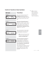
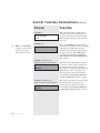
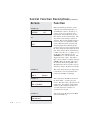
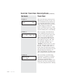
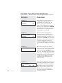
Control Function Descriptions
Screen
Function
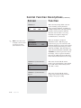
SCREEN 1
Once power is turned on, this screen is
displayed for 3 seconds. It shows
CONAIR and the dryer type on the first
line, and the control program version and
display program version on the second
line.
✐
NOTE: The supervisory
password is required to
change certain parameters.
More detail about the
CONAIR
D100
CV2.21.00
DV2.21.00
SCREEN 2
MONDAY
07/22/03
07:59 AM
ACT 350°F
SET 350°F
Once power is turned on and screen 1 is
displayed for 3 seconds, this screen is
displayed for another 3 seconds. It shows
the day of the week on the first line and
the date and time on the second line. If
this information is not correct, it can be
changed under the SETUP, DISP, DATE
TIME screen 73, page 4-25.
Shows the regeneration air setpoint and
actual temperature. The setpoint can be
changed with the correct password.
✐
NOTE: Lowering the regeneration setpoint
decreases the capacity of the dryer and
normally is not recommended. Use the
dewpoint control function instead.
SCREEN 5
RETURN AIR TEMP
ACT 100°F
SET 100°F
Shows the actual return air temperature
measured at the inlet to the process
blower. (The return air temperature on
W1600-5000 dryers is measured at the
inlet to the desiccant wheel. W1600-5000
dryers designed prior to August 2007, the
return air temperature is measured at the
inlet to the process blower.)
If the optional aftercooler/intercooler flow
control is installed, a setpoint will be displayed on this screen as well. The setpoint can be changed with the correct
password.
Operation l 4-11
4
REGENERATION TEMP
under screen 85, page 4-29.
Operation
SCREEN 4
password can be found
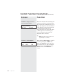
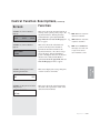
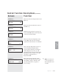
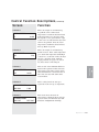
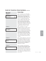
C o n t r o l F u n c t i o n D e s c r i p t i o n s (continued)
Screen
Function
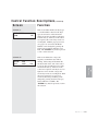
SCREEN 11 Dewpoint Control
and/or Dewpoint Monitor
This screen will show the actual dewpoint
of the process delivery air measured after
the desiccant wheel and before the process
heater. The dewpoint control will automatically adjust the regeneration temperature
to maintain the dewpoint setpoint.
Dewpoint control is not active with -40°F
{-40°C} setpoint. See screen 24, page
4-15 for information about using the
dewpoint control or monitor.
PROCESS DEWPOINT
ACT -47°F
SET -40°F
✐
NOTE: Dewpoint actual will not be live for
approximately 5 to 8 minutes.
SCREEN 12 (MAIN MENU)
DRYER MAIN MENU
STAT
4-12
l Operation
SETUP
DIAG
This is the dryer MAIN MENU. It can be
located by pressing the “MENU” key
while at the DEFAULT screen. By pressing the Select Category buttons under the
titles, the user goes to STATUS screens,
SETUP screens, or DIAGNOSTIC
screens.
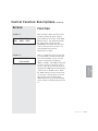
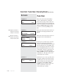
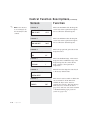
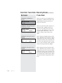
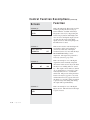
C o n t r o l F u n c t i o n D e s c r i p t i o n s (continued)
Screen
Function
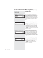
SCREEN 13
This is the Dryer Status screen. It can be
found by pressing the Select Category
button under the word "Stat" on the Main
Menu screen 12. Any information under
the status section is read only; NO
CHANGES can be made from the status
sections. The operator can select to see
status information for Process,
Regeneration, or Other.
DRYER STATUS
PROC
REGEN
OTHER
SCREEN 14
DRYER PROCESS
STATUS SCREEN
Operation l 4-13
4
Operation
This is a column title screen. To navigate
to screens within a column (reference the
flow charts beginning on page 4-4), the
operator must use the scroll buttons,
“Prev” or “Next”. The “Next” button will
scroll one screen at a time down a list of
screens. Once the last screen in the list is
displayed the “Next” button will return the
operator back to this Title screen. When
the “Prev” button is pressed, it will scroll
one screen at a time up the list of screens.
Once the title screen is displayed the
“Prev” button will go up to the next high
screen, in this case the Dryer Status screen
13.
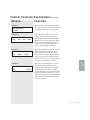
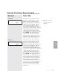
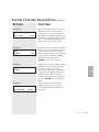
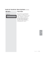
C o n t r o l F u n c t i o n D e s c r i p t i o n s (continued)
Screen
Function
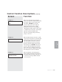
SCREEN 17
This screen shows the total run time in
hours the dryer has been running since it
was new. If the control board is changed
during the life of the dryer, this timer will
start over.
TOTAL RUN HOURS
1250
✐
SCREEN 20
NOTE: Screens labeled 75 in
the display screen flow chart
PROCESS CFM 1600
on page 4-9 are various
option installation screens.
SCREEN 21 (Aftercooler/
Intercooler Flow Control Option)
AFTERCOOLER
ENABLED
SCREEN 21 (Aftercooler/
Intercooler Flow Control Option)
AFTERCOOLER
FLOW ON
4-14
l Operation
This is the CFM Monitor screen. It displays the Process CFM. The Process CFM
is measured by a differential pressure
transducer across the inlet and the outlet of
the process blower. The CFM Monitor
option must be installed (see screen 75,
page 4-26, also see note on this page) for
this to appear.
This screen shows if the aftercooler/intercooler flow control option is enabled. If
the aftercooler/intercooler is disabled,
there will be no setpoint for the Return Air
Temperature screen 5. The aftercooler/
intercooler flow control option must be
installed (see screen 75, page 4-26, also
see note on this page) for this to appear.
This screen shows if the control is opening
the solenoid valve. The aftercooler/
intercooler flow control option must be
installed (see screen 75, page 4-26, also
see note this on page) for this to appear.
C o n t r o l F u n c t i o n D e s c r i p t i o n s (continued)
Screen
Function
SCREEN 22 (Current Monitor
Option)
This screen shows the measured current on
each leg of the 3-phase power going to the
regeneration heater. The Regeneration
Current Monitor option (see screen 75,
page 4-26, also see note on this page) for
this to appear.
REGEN CURRENTS
84.3 A
84.2 A
84.3 A
SCREEN 23 (Current Monitor
Option)
TOTAL POWER
82 KWH
✐
NOTE: Additional components
required for installation.
NOTE: Additional components
required for installation.
✐
NOTE: Screens labeled 75 in
the display screen flow chart
on page 4-9 are various
option installation screens.
This screen displays the average dewpoint
over the last hour of run time.
DEWPOINT CONTROL
AVG
-55°F
SCREEN 29 (Regeneration Outlet
Temperature)
REGEN OUTLET TEMP
This screen shows the actual temperature
measured at the regeneration outlet of the
desiccant wheel manifold.
ACT 280
Operation l 4-15
4
Operation
SCREEN 24 Dewpoint Control
and Dewpoint Monitor
This screen shows the calculated total
power for the dryer. The calculation
includes the measured current for the
regeneration heaters, the control voltage
set for the dryer, and pre-determined
power consumption values for the blowers
and the control. The Current Monitor
option (see screen 75, page 4-26, also see
note on this page) for this to appear.
✐
C o n t r o l F u n c t i o n D e s c r i p t i o n s (continued)
Screen
Function
SCREEN 30
✒
Tip: This information is
important to know when
ordering a control board.
✒
Tip: This information is
important to know when
ordering a display board.
MODEL
CP600-5000
480 V
60 Hz
SCREEN 31
DISPLAY FIRM
V2.21.00
DISPLAY MENU
V2.21.00
SCREEN 32
CONTROL FIRMWARE
VERSION
23:05:53
SCREEN 34
AUTOSTOP COUNT DOWN
3 DAYS
4-16
l Operation
This screen shows the current versions of
program for the Display Firmware and
Menus.
This screen shows the current versions of
program for the Control Firmware.
V2.21.00
SCREEN 33
AUTOSTART COUNT DOWN
1 DAYS
This screen shows the model number,
voltage, and frequency for which the
dryer control is setup. These values can
be changed with the proper password on
screen 85, see page 4-27 (screen 80) under
SETUP, OTHER, INSP, Model number
(screen 78), and Voltage FREQ (screen
80).
11:04:23
If the dryer is set with an auto start time,
this screen will appear and show the
amount of time remaining before the dryer
will automatically start. The LED on the
front of the display, beside the word Auto
Start, will flash if the dryer is set to start
automatically. The auto start feature can
be programmed under SETUP, PROC,
PROC, OTHER (screens 55 and 56, pages
4-20 and 4-21). The dryer can be set to
automatically start each day.
If the dryer is set to auto stop, this screen
will appear and show the amount of time
remaining before the dryer will automatically stop. The auto stop feature can be
programmed under SETUP, PROC,
OTHER (screens 55 and 57, pages 4-20
and 4-21). The dryer can be set to
automatically stop each day.
C o n t r o l F u n c t i o n D e s c r i p t i o n s (continued)
Screen
Function
SCREEN 35
This screen shows the temperature inside
the control enclosure. It is measured at the
lower right corner of the control board.
PANEL INSIDE TEMP
ACT 100°F
SCREEN 36
DRYER SETUP
SCREEN 37
PROC
ALM
DISP
OTHER
SCREEN 37
SETUP PROCESS
SCREEN 38
PROC
REGEN
OTHER
PROC
RETPID
This is the second Setup Process screen.
It can be found by pressing the Select
Category button under the word "PROC"
on the Setup Process screen (37). By
pressing the Select Category buttons under
the titles, the user can select to see setup
information for Process or Return Air PID
if the optional aftercooler/intercooler flow
control is installed.
Operation l 4-17
4
SETUP PROCESS
This is the Setup Process screen. It can be
found by pressing the Select Category
button under the word "PROC" on the
Dryer Setup (screen 36). By pressing the
Select Category buttons under the titles,
the user can select to see setup information
for Process, Regeneration, or Other.
Operation
SCREEN 38
This is the Dryer Setup screen. It can be
found by pressing the Select Category
button under the word Setup on the Main
Menu (screen 12). By pressing the Select
Category buttons under the titles, the user
can select to see setup information for
Process, Alarms, Display, or Other.
C o n t r o l F u n c t i o n D e s c r i p t i o n s (continued)
Screen
Function
SCREEN 40
Before performing an autotune, set the
setpoint to the desired temperature you
would like the control to autotune to at
screen 3 for process, and screen 4 for
regeneration. Screen 40 shows the autotune function for the selected heater. The
dryer must not be running to initiate an
autotune. The autotune should be started
from a cold start or a minimum of 50ºF
{28ºC} difference between starting and
autotune temperatures. With the proper
password, (see page 4-29, screen 85) press
the Select Category button under the word
Off. Once selected, the word should start
to blink. Press the (+) or (-) button to toggle the Off to On and then press the
“ENTER” key to start the autotune. The
display will show " Wait", then "Heat",
then " Done" when it is complete. Pressing
“STOP” during an autotune will cancel
the autotune and not change PID values.
The PID values can be set back to factory
defaults by going to the Reset (screen 46).
PROCESS PID
DONE
AUTOTUNE
OFF
and
REGEN PID
DONE
AUTO
SCREEN 41
REGEN POWER LIMIT
SCREEN
LOW 2% 37
HIGH 80%
SCREEN 42
REGEN CYCLE TIME
HEAT 2.0 SECONDS
SCREEN 43
REGEN PROP BAND
HEAT/COOL 30°F
4-18
l Operation
This screen shows the power output range
for the heater. It is set by default to 0%
for the low and 100% for the high.
This screen shows the PID cycle time for
the heater "Heat", or with a precooler
"Cool". This time value is the time for one
on/off cycle. For example, with a heater
running at 50% and the cycle time set at
2 seconds, the heater would be on 1
second and off 1 second.
This screen shows the Proportional Band
value for the PID loop.
C o n t r o l F u n c t i o n D e s c r i p t i o n s (continued)
Screen
Function
SCREEN 44
This screen shows the integral value for the
PID Loop.
REGEN INTEGRAL
HEAT/COOL
16.0
This screen shows the derivative value for
the PID Loop.
SCREEN 45
REGEN DERIVATIVE
HEAT/COOL
2.0
With the proper password, (see page 4-29,
screen 85) the PID values can be reset back
to the factory default settings.
SCREEN 46
REGEN PID RESET
HEAT/COOL
This screen shows the temperature offset
for the RTD. This screen is used if the
regeneration readout needs to be calibrated.
SCREEN 47
REGEN CALIBRATION
2°F
SETUP REGENERATION
PID
SCREEN 49
PROCESS DEWPOINT
SAMPLE RATE
150 SEC
This is the amount of time the control
waits before checking the dewpoint value
after making a change. This time value
gives the system time to respond to a
process change.
✐
NOTE: Screens 49, 50, 51,
52, 53 and 54 apply only
when the dewpoint control
is enabled.
Operation l 4-19
4
This is the Setup Regeneration screen. It
can be found by pressing the Select
Category button under the word “Regen”
on the Setup Process screen (37). By
pressing the Select Category buttons under
the titles, the user can select to see setup
information for Regeneration or
Regeneration PID.
SCREEN 48
REGEN
Operation
OFFSET
C o n t r o l F u n c t i o n D e s c r i p t i o n s (continued)
Screen
Function
✐
NOTE: Screens 49, 50, 51,
52, 53 and 54 apply only
when the dewpoint control
is enabled.
SCREEN 50
PROCESS DEWPOINT
TRIM UP LIMIT
375°F
This is the minimum value the dewpoint
control can set the regeneration temperature to achieve the desired dewpoint.
SCREEN 51
PROCESS DEWPOINT
TRIM LOW LIMIT
100°F
This is the proportional gain value for the
dewpoint control.
SCREEN 52
PROCESS DEWPOINT
GAIN
0.7
SCREEN 53
PROCESS DEWPOINT
DEADBAND
This is the maximum value the dewpoint
control can set the regeneration temperature to achieve the desired dewpoint.
1
This is the deadband range. If the actual
dewpoint value is within this range of the
dewpoint setpoint, the control will not
make a change to the regeneration
temperature.
This will reset the dewpoint control back
to the factory default values.
SCREEN 54
PROCESS DEWPOINT
CONTROL RESET
SCREEN 55
AUTO START TIMER
ENABLED
4-20
l Operation
EDIT
This screen is used to enable or disable the
auto start function. If the function is
enabled, the dryer can be started or
stopped once each day. The start and stop
times can be set on screens 56 and 57
(page 4-21). The auto start can be enabled
or disabled with the proper password
(screen 85, page 4-29).
C o n t r o l F u n c t i o n D e s c r i p t i o n s (continued)
Function
Screen
SCREEN 56
MONDAY START TIME
ON
8:00 AM
SCREEN 57
8:00 PM
NOTE: Screens 56 and 57
require the supervisor’s
password.
This is the auto stop screen for the first
day of the week. Each day has a screen
similar to this. By pressing the Select
Category button under On or Off, the dryer
can be set to stop on Monday. The stop
time can be set by pressing the Select
Category button under time and entering a
new time on the numeric keypad. The AM
/ PM can be changed only after a time
value has been entered. The (+) button
will set PM and the (-) button will set AM.
The “ENTER” key must be pressed to
lock in the new time. If the auto stop time
runs out and the dryer has already been
manually stopped, nothing will happen. If
the dryer was auto started on Monday
morning and the Monday auto stop is set
to off, the dryer will continue running until
it hits a day of the week when the auto
stop is set to On. At that time the dryer
will turn off.
Operation l 4-21
4
ON
✐
Operation
MONDAY STOP TIME
This is the auto start screen for the first
day of the week. Each day has a screen
similar to this. By pressing the Select
Category button under On or Off, the dryer
can be set to start on Monday. The start
time can be set by pressing the Select
Category button under time and entering a
new time on the numeric keypad. The AM
/ PM can be changed only after a time
value has been entered. The (+) button
will set PM and the (-) button will set AM.
The “ENTER” key must be pressed to
lock in the new time. The dryer can be
manually started at anytime. If the auto
start time runs out and the dryer has been
manually started, nothing will happen.
C o n t r o l F u n c t i o n D e s c r i p t i o n s (continued)
Screen
Function
SCREEN 58
This is the alarm action and setup screen.
With the proper password, (see page 4-29,
screen 85) the Select Category button can
be pressed under Alarm Action or Alarm
Setup. Alarm Action screens can be used
to change whether an alarm is Off,
Passive, or Shutdown (screen 59). Alarm
Setup screens can be used to change alarm
setpoints and delay times. (screens 60-70)
ALARM
ALARM
ACTION
SETUP
SCREEN 59
REGEN TEMP DEVIATION
ON
EDIT
SCREEN 60
REGEN HIGH TEMP
250°F
4-22
l Operation
1 SEC
PASS
EDIT
This is an example of the Alarm Action
screens. With the proper password, (see
page 4-29, screen 85) some alarms can be
turned on or off by either pressing the
Select Category button under the word
Edit, or by pressing the Select Category
button under the word On or Off. Once
the word begins to blink, the (+) or (-)
keys will change the setting. The
“ENTER” key must be pressed to lock in
the value. The same sequence works for
the “Pass” or “Shut” words. “Pass” or
Passive means the alarm will not shut the
dryer down but the alarm will be logged in
the Dryer Diagnostics Alarm Log. A
“Shut” means Shutdown, in which case the
dryer would shut down if the alarm occurs.
This is an example of an Alarm Setup
screen that has a minimum or maximum
temperature. With the proper password,
(see page 4-29, screen 85, refer to
password) the temperature setpoint can be
changed as well as how long the dryer has
to stay at that temperature before alarming.
C o n t r o l F u n c t i o n D e s c r i p t i o n s (continued)
Screen
Function
SCREEN 61
This is an example of an Alarm Setup
Loop Break screen. When actual
temperature is outside the deviation band,
if the temperature is not moving toward
the setpoint at a rate greater than or equal
to X°F over Y seconds, then the dryer will
alarm on Loop Break. Once the actual
temperature is within the deviation band,
the Loop Break is ignored.
REGEN LOOP BREAK
2°F
40 SEC
SCREEN 62
REGEN TEMP DEV
10°F
5 Sec
SCREEN 63
10 SEC
This is a delay time from start-up so
regeneration can come up to temperature.
SCREEN 64
REGEN DIFFERENTIAL
TIME DELAY
5 MIN
SCREEN 65
RETURN AIR ALARMS
PASS 150°F
SHUT 180°F
This screen shows the return air
temperatures at which the dryer will give
a passive alarm, and when the dryer will
shutdown on High Return Air Temp.
Operation l 4-23
4
20°F
This set value is the minimum difference
between the regeneration inlet and outlet
temperature for the wheel rotation alarm.
Once this difference is reached for the set
time value, the dryer will alarm wheel
rotation failure.
Operation
REGEN DIFFERENTIAL
This is an example of an Alarm Setup
deviation screen. If the actual temperature
goes outside this temperature band (High
or Low) for a set amount of time, the dryer
will give a deviation alarm. With the
proper password (see page 4-29, screen
85), these values can be changed.
C o n t r o l F u n c t i o n D e s c r i p t i o n s (continued)
Screen
Function
SCREEN 66 (CFM Monitor
Option)
This screen shows the low CFM setpoint.
The default is 1 CFM. The default can be
changed with the proper password (see
page 4-29, screen 85).
CFM LOW SETPOINT
1430
SCREEN 67 (Dewpoint Monitor
or Dewpoint Control)
DEWPOINT ALARM
ACT -40°F
180 SEC
SCREEN 68 (Dewpoint Control
Enabled)
DEWPOINT71DEVIATION
SCREEN
HIGH
5°F
30 SEC
SCREEN 69 (Dewpoint Control
Enabled)
DEWPOINT DEVIATION
LOW 5°F
4-24
l Operation
30 SEC
This screen shows the alarm setpoint for a
Dewpoint alarm. With the proper password, it can be changed (see page 4-29,
screen 85). The defaults are -3°F for 180
seconds. If the control senses -3°F or
higher for 180 seconds, the dryer will
alarm.
This is the dewpoint high deviation alarm
value. With the proper password, it can be
changed (see page 4-29, screen 85). When
in dewpoint control, if the actual dewpoint
goes above the setpoint in screen 11, page
4-12, for the set amount of time, the dryer
will alarm “Dewpoint Deviation High”.
This is the dewpoint low deviation alarm
value. With the proper password, it can be
changed (see page 4-29, screen 85). When
in dewpoint control, if the actual dewpoint
goes below the setpoint in screen 11, page
4-12, by this value for this amount of time,
the dryer will alarm “Dewpoint Deviation
Low”.
C o n t r o l F u n c t i o n D e s c r i p t i o n s (continued)
Screen
Function
SCREEN 70
DEWPOINT
TIME
DELAY
5 MIN
SCREEN 71
UNITS
STANDARD
EDIT
This is the amount of time from start-up
the dryer is allowed to run before the
control will try to control the dewpoint.
Five minutes is the default. This gives the
dryer time to warm up and reach a steady
state. It can be changed with the proper
password (see page 4-29, screen 85).
This screen shows the units the dryer will
display. It can be changed with the proper
password (see page 4-29, screen 85) to
either Standard or Metric. Press the Select
Category button below the word Edit to
change the setting and press the
“ENTER” key to lock in the value.
TIME DISPLAY
SCREEN 73
DATE
TIME
10/25/2004 MON
10:33 AM
This screen shows the date and time.
With the proper password, (see page
4-29, screen 85) the date and time can
be changed.
Operation l 4-25
4
12 HOUR
Operation
This screen shows the time unit the dryer
will display. It can be changed with the
proper password (see page 4-29,
screen 85) to either 12 hour (AM / PM
Clock) or 24 hour (Military Time). Press
the Select Category button below the
words 12 hour to change the setting and
press the “ENTER” key to lock in the
value.
SCREEN 72
C o n t r o l F u n c t i o n D e s c r i p t i o n s (continued)
Screen
Function
SCREEN 74
This is the Dryer Setup Other screen. It
can be found by pressing the Select
Category button under the word Other on
the Dryer Setup Screen (36). By pressing
the Select Category buttons under the
titles, the user can select to see setup
information for Options, Inspection,
Communications, or Password.
DRYER SETUP OTHER
OPT
✐
INSP
COM
PW
SCREEN 75
NOTE: Screens labeled 75 in
the display screen flow chart
on page 4-9 are various
option installation screens.
CFM MONITOR
NOT INSTALLED
EDIT
SCREEN 76 (Current Monitor
Option)
REGEN CURRENT
TAP
This is an example of an Option
Installation screen. With the proper
password (see page 4-29, screen 85) and
hardware installed, an option can be turned
on by pressing the Select Category screen
under the word Edit. This will change an
option from Not Installed to Installed. The
“ENTER” key must be pressed to lock in
the change. Once an option is installed,
there may be additional screens that show
in the menu structure that need to be setup.
This screen is used with the current
monitor option and tells the control which
tap is used on the current sensing board
(5A, 10A, or 15A).
5A
SCREEN 77 (Current Monitor
Option)
REGEN CURRENT SCALE
1
4-26
l Operation
This screen is used with the current
monitor option and is used to scale the
reading to the proper reading.
C o n t r o l F u n c t i o n D e s c r i p t i o n s (continued)
Screen
Function
SCREEN 78
This screen further defines the dryer type
to a model number. Based on the dryer
type, the selections on this menu will
change. Your dryer should be configured
from the factory. However, if the control
was replaced, the control may need to be
reconfigured. With the proper password,
(see page 4-29, screen 85) the Model
Number can be changed by pressing the
Select Category button under the word
Edit. The “ENTER” key must be pressed
to lock in the selection.
MODEL NUMBER
CP600
EDIT
SCREEN 80
VOLTAGE
FREQ
208 V
60 HZ
EDIT
Operation l 4-27
4
Operation
This screen defines the voltage and
frequency at which the dryer will be
running. This setting should match the
electrical label on the side of the control
box. Your dryer should have been configured from the factory. However, if the
control was replaced or the dryer was configured to run on another voltage, this
screen may need to be reconfigured. With
the proper password, (see page 4-29,
screen 85) the Voltage and Freq can be
changed by pressing the Select Category
button under the word Edit. The
“ENTER” key must be pressed to lock in
the selection.
C o n t r o l F u n c t i o n D e s c r i p t i o n s (continued)
Screen
Function
SCREEN 81 Communications
This screen shows the communications
protocol. Modbus, DeviceNet, Ethernet or
SPI is available. This is set at the factory.
If adding to an existing dryer, the communications protocol can be changed with the
proper password (see page 4-29, screen
85).
PROTOCOL
DEVICENET
EDIT
SCREEN 82 Communications
SLAVE ID
1
EDIT
SCREEN 83 Communications
BAUD RATE
9600
EDIT
SCREEN 84 Communications
PARITY
NONE
4-28
l Operation
EDIT
This screen shows the Slave ID number.
The ID number can be changed with the
proper password (see page 4-29, screen
85) by pressing the Select Category button
below the word Edit and entering a value
on the keypad or scrolling to the desired
value using the Adjust Setpoint keys. The
“ENTER” key needs to be pressed to lock
in the new number.
This screen shows the baud rate. The
baud rate can be changed with the proper
password (see page 4-29 screen 85). Press
the Select Category key below the word
Edit and enter a value on the keypad or
scroll to the desired value using the Adjust
Setpoint keys.
This screen shows the parity. The parity
can be changed with the proper password
(see page 4-29, screen 85) to Even, Odd,
or None by pressing the Select Category
button below the word Edit. The
“ENTER” key needs to be pressed to
lock in the new number.
C o n t r o l F u n c t i o n D e s c r i p t i o n s (continued)
Screen
Function
SCREEN 85
This screen shows the password entry
screen. You can enter a password by using
the keypad. Once a password has been
entered the “ENTER” key must be
pressed. If the password is valid, the
display will show screen 87. If the
password was incorrect, it will display
"Invalid Password Try Again" and go back
to the Enter Password screen. The default
supervisor password is 0210. The
supervisor can change this password by
going to screen 89.
ENTER PASSWORD
0210
SCREEN 86
RESET PASSWORD
PASSWORD ENTERED
This is the display screen that appears
when a valid password has been entered.
Pressing the Previous button will take you
to screen 14. Pressing “Next” will take
you to screen 88.
Operation l 4-29
4
VALID SUPERVISOR
Operation
SCREEN 87
This is the Reset Password screen. It will
only be shown when the second and fourth
Select Category buttons are pressed at the
same time when at screen 85. You can
enter the default password by using the
keypad. Once the default password has
been entered, the “ENTER” key must be
pressed. This will change the password
back to the factory default password (see
page 4-29, screen 85). If the password has
been changed see screens 89 and 90.
C o n t r o l F u n c t i o n D e s c r i p t i o n s (continued)
Screen
Function
SCREEN 88
This is the password logout screen. If
nothing is done, the password will
automatically be logged out after 30
minutes. To logout, use the Select
Category button under the word Yes/No.
Setting it to Yes and hitting the “ENTER”
Key will change the display to "Logging
Out Password" for 3 seconds then will
automatically go to screen 14.
LOGOUT SUPERVISOR
PASSWORD
YES
SCREEN 89
CHANGE SUPERVISOR
PASSWORD
YES
SCREEN 90
This screen shows the password entry
screen. You can enter a new password by
using the key pad. Once a new password
has been entered the “ENTER” key must
be pressed. The display will show the new
password for 3 seconds then return to the
Change Supervisor Password (screen 89).
To exit, press the “Next” key and the
control will return to the Dryer Setup
Password Screen.
ENTER NEW PASSWORD
SCREEN 91
DRYER DIAGNOSTIC
ALRM
4-30
l Operation
HIST
This screen allows the supervisor to
change the password. To change the
password, use the Select Category button
under the word, Yes/No. Setting it to yes
and hitting the “ENTER” Key will change
the display to screen 90. If the user does
not want to change the password, by
pressing the “Next” key the control will
return to the Dryer Setup Password screen
14.
I/O
This is the Dryer Diagnostic screen. It can
be found by pressing the Select Category
button under the word Diag on the Dryer
Main Menu screen 12. By pressing the
Select Category buttons under the titles,
the user can select to see diagnostic
information for Alarms, Alarm History,
or Inputs and Outputs.
C o n t r o l F u n c t i o n D e s c r i p t i o n s (continued)
Screen
Function
SCREEN 92
This is an example of one of the alarm
history screens. The first two numbers of
the first line show what alarm you are
viewing in the list. This example is the
first alarm in the list 00. The letter after
the : P or : S shows if the alarm was a
passive or shutdown alarm. The second
line shows the date and time when the
alarm occurred. By pressing the Select
Category button under the word Info, the
display can show a number of screens that
are a snapshot of information that was
happening when the alarm occurred.
00:S-REGEN RTD
1/31/00 09:24 P
INFO
ALARM ACTIVATED FOR
10.3 MINUTES
DIAGNOSTIC EVENTS
ALARMS
SCREEN 95
REGEN HIGH TEMP
P-0
This is an example of the Event Freq.
screens. This shows the number of times
an alarm has occurred. By pressing the
next key in this section, the user can see
info for all alarms. The “S” indicates how
many times it was a shutdown alarm and
the “P” indicates how many times it was a
passive alarm.
Operation l 4-31
4
This is the Dryer Diagnostic screen. It can
be found by pressing the Select Category
button under the word Hist on the Dryer
Diagnostics screen (91). By pressing the
Select Category buttons under the alarms,
the user can select to see diagnostic
information for Alarms.
SCREEN 94
S-0
Operation
This is an example of one of the
Information screens for an alarm. This is
the first screen under the Info shown on
screen 92. It shows how long the alarm
was active. The time shown is from when
the alarm occurred until the alarm was
acknowledged and cleared. The “Next”
button can be pressed while at this screen
to see other items in the list of snapshot
info that was happening when the alarm
occurred.
SCREEN 93
C o n t r o l F u n c t i o n D e s c r i p t i o n s (continued)
Screen
Function
SCREEN 96
This is the Diagnostic I/O screen. It can be
found by pressing the Select Category
button under the word I/O on the Dryer
Diagnostics screen (91). By pressing the
Select Category button under Digital, the
user can access the digital outputs (screen
98) and view the status of the digital
inputs (screen 99). The analog diagnostic
I/O function is not used.
DIAGNOSTIC I/O
DIGITAL
SCREEN 97
START DIGITAL I/O
DIAGNOSTICS
OFF
SCREEN 98
PROCESS BLOWER
ON
SCREEN 99
PROC
OPEN
4-32
l Operation
OFF
JOG
This screen is used to enter the diagnostic
mode where outputs can be turned on
(screen 98) or the state of the inputs
monitored (screen 99). Note that the dryer
MUST NOT BE running to enter
diagnostics. The supervisor password is
necessary (screen 85, page 4-29).
This is an example of one of the digital
outputs that can be manually energized.
All screens in this section only work when
the dryer is not running and is in “standby”. The outputs can be turned on, turned
off, or energized for a 3-second jog (automatically turned on for 3 seconds then
turned off). The process and regeneration
heaters can only be jogged for 3 seconds,
and the wheel motor, if jogged, will rotate
the wheel for 3 seconds. If the stop button
is pressed at any time during this testing,
the output will stop immediately.
This is an example of one of the digital
Inputs screens. This will show if the input
is open or closed.
C o n t r o l F u n c t i o n D e s c r i p t i o n s (continued)
Screen
Function
SCREEN 102
These parameters map which internal
variables are accessible from the user
communication port on the DC-2 operator
display. A default set of variables has
been chosen that represent the most
important variables for the majority of
uses. These values should NOT be
changed except under the direction of
Conair Engineering or Service.
MAP INDIRECT REG 500
0
4
Operation
Operation l 4-33
To S t a r t D r y i n g
1 Make sure there is material in the hopper.
2 Turn on the main power to the dryer. Make sure the dryer’s disconnect dial
is in the ON position. This powers up the control and the display lights will
illuminate.
✐
NOTE: When changing a setpoint use the Select Category Key directly below the value
to be changed. Once pressed the value will blink, then use the keypads or (+) (-)
adjustment setpoints to enter the new value. Then press enter for the new value to be
recognized.
✐
NOTE: Once the dryer has been started, go to the ResinWorks or HTC and set the
setpoint then turn on the unit.
Menu
3
3
Select
Category
Process Blower
Prev
Scroll List
Regen. Blower
Auto Start
Regen. Heater
Dewpoint Control
Next
1
2
3
4
5
6
7
Clear
8
0
9
Adjust Setpoint
Acknowledge
Alarm
Start
Stop
Enter
1000
Select
Category
Buttons
Setpoint
Adjustment
Buttons
(continued)
4-34
l Operation
To S t a r t D r y i n g
(continued)
3 Press the START button.
Start
If everything is installed correctly:
• The green light on the start button will illuminate.
• The process and regeneration blowers turn on and the display
LEDS will illuminate.
• The regeneration heater turns on and the display LED will
•
illuminate.
The desiccant wheel starts turning.
To S t o p D r y i n g
✐
NOTE: Turn off the ResinWorks or HTC and allow the heaters to cool (3 to 5 minutes)
before turning off the dryer.
Stop
to cool the heaters.
2 Be sure to disconnect and lockout the main power if you have stopped the
dryer to perform maintenance or repair.
IMPORTANT: Do not use the main power switch to stop the dryer. Turning off power to the
control and dryer during normal operation prevents the necessary cool-down period, and
can trigger the shut down/high temperature alarm during your next drying cycle.
Caution: Improper shut down can cause damage to your dryer.
Operation l 4-35
4
Operation
1 Press the STOP button. The Stop LED blinks red.
• The blowers continue running for a few minutes
H o w t o U s e t h e S u p e r v i s o r ’s
Pa s s w o r d
The supervisor's password must be entered before you can use or make changes to
some screens on the dryer control. To enter the supervisor password:
1 Go to screen 12 and press the Select Category button under "SET UP."
DRYER MAIN MENU
STAT
SETUP
DIAG
2 This will take you to screen 36. On Screen 36, press the Select Category
button under "other."
DRYER SETUP
PROC
ALM
DISP
OTHER
3 This will take you to screen 74. On Screen 74, press the Select Category
button under "PW."
DRYER SETUP OTHER
OPT
INSP
COM
PW
4 This will take you to screen 14. On Screen 14, press the Scroll List Next
button. This will take you to screen 85.
DRYER PROCESS
STATUS SCREEN
ENTER PASSWORD
0210
5 This is the screen where you will need to enter the supervisor's password.
The default supervisory password in 0210. Enter this number to make changes
to screens where the supervisor’s password is necessary to use or change a
function of the dryer.
(continued)
4-36
l Operation
H o w t o U s e t h e S u p e r v i s o r ’s
Pa s s w o r d ( c o n t i n u e d )
Be sure to push “ENTER” after entering the password. If the password is
entered successfully, screen 87 will be displayed.
VALID SUPERVISOR
PASSWORD ENTERED
Once the desired parameter has been changed, follow the previous steps to go
to screen 88.
LOGOUT SUPERVISOR
PASSWORD
YES
Push the Select Category button under “No”. Once it begins to flash, push
either the Adjust Setpoint button to display “Yes”, then push “ENTER”. Push
the Menu button to return to the main display.
✐
changing the supervisory password.
Operation l 4-37
4
Operation
NOTE: The supervisor's password can be changed by going to screen 89, see page
4-4, for the map of the screens. See page 4-30, screen 89 for additional information on
Using the Dewpoint Monitor and
Dewpoint Control
Your dryer is equipped with a dewpoint monitor and dewpoint control features.
You can choose to use it as a monitor only device, or to maintain a steady
dewpoint that you select with the dewpoint control. Dewpoint control will vary
the regeneration air temperature to condition the desiccant to the level necessary
to maintain the desired dewpoint.
Dewpoint Monitor
✐
NOTE: The supervisor's password is necessary. Please refer to the “Using the Supervisor’s
Password” section on page 4-36.
From “Dryer Main Menu”, select “Setup, Other OPT” to get to the “Dryer
Setup Options Information” (screen 14, page 4-13). Proceed to screen 75 (page
4-26). “Dewpoint Monitor” must be set to “Installed” and “Dewpoint Control”
set to “Not Installed”. Screen 11 (page 4-12) will display the actual dewpoint
readout.
Dewpoint Control
✐
NOTE: The supervisor's password is necessary. Please refer to the “Using the Supervisor’s
Password” section on page 4-36.
From “Dryer Main Menu”, select “Setup, Other OPT” to get to the “Dryer
Setup Options Information” (screen 14, page 4-13). Proceed to screen 75 (page
4-26). “Dewpoint Control” must be set to “Installed”. “Dewpoint Monitor”
can be set to “Installed” or “Not Installed”. Screen 11 (page 4-12) will display
the actual dewpoint and the dewpoint setpoint the dryer is to maintain.
✐
✐
NOTE: Dewpoint control is inactive when the dewpoint setpoint is -40° F {-40° C}.
NOTE: For more information concerning specific dewpoint control screens, see Control
Function Descriptions, page 4-11.
4-38
l Operation
U s i n g t h e A u t o S t a r t Ti m e r
You can set the dryer to start and stop automatically using the Auto Start and
Auto Stop functions. Supervisor Password (screen 85, page 4-29) is necessary
to use this function.
✐
NOTE: To use the
Auto Start Timer, you
must have the Auto
Programming Auto Start
Start function enabled
The Auto Start time and day can be programmed using the Auto Start
Countdown screen. This screen can be accessed under the SETUP, PROC, and
OTHER screens from the “Dryer Main Menu” screen 12:
SCREEN 36
SCREEN 37
(screen 55, page 4-
Setup Process
Dryer Setup
Proc
Alm
Disp
20).
Other
Proc
Regen
Other
SCREEN 56
MONDAY START TIME
ON
8:00 AM
Programming Auto Stop
The Auto Stop time and day can be programmed using the Auto Stop
Countdown screen. This screen can be accessed under the SETUP, PROC, and
OTHER screens from the “Dryer Main Menu” screen 12:
SCREEN 36
SCREEN 37
Setup Process
Dryer Setup
Proc
Alm
Disp
Other
Proc
Regen
Other
SCREEN 57
MONDAY STOP TIME
ON
8:00 PM
Once the Auto Stop time and day has been programmed, the Auto Stop
Countdown screen (screen 34) will show the amount of time remaining before
the dryer will automatically stop. The dryer can be set to automatically stop
each day.
Operation l 4-39
4
Operation
Once the Auto Start time and day has been programmed, the Auto Start
Countdown screen (screen 33) will show the amount of time remaining before
the dryer will automatically start. The LED on the front of the display beside
the word Auto Start will flash if the dryer is set to start automatically. The
dryer can be set to automatically start each day.
4-40
l Operation
SECTION
5
Maintenance
Preventative maintenance checklist . . . . . . . 5-2
Checking the dewpoint . . . . . . . . . . . . . . . . 5-3
Cleaning the hopper. . . . . . . . . . . . . . . . . . 5-5
Cleaning the process filter . . . . . . . . . . . . . 5-6
Cleaning the regeneration filter . . . . . . . . . . 5-8
Cleaning the aftercooler/intercooler coils . . . 5-9
Cleaning the precooler coils (W600-5000) . . 5-11
Inspecting hoses and gaskets . . . . . . . . . . 5-11
Maintenance l 5-1
5
Maintenance
Cleaning the volatile trap on the demister . . 5-11
Preventative Maintenance
Checklist
Routine maintenance will ensure optimum operation and performance of the
W Series Carousel Plus Dryer. We recommend the following maintenance
schedule and tasks.
• Whenever you change materials
❒ Drain and clean the hopper.
• We e k l y, o r a s o f t e n a s n e e d e d
❒ Clean or replace the process and regeneration filters.
You may need to clean filters more often than weekly. Frequency depends
on how much material you process and how dusty or full of fines it is.
❒ Inspect hoses and hose connections.
Check for damage, kinks, or loose hose clamps. Replace any hoses that
show signs of damage or wear. Reposition and tighten loose hose clamps.
• Monthly
❒ Clean the aftercooler/intercooler and/or optional precooler coils.
You may need to clean the coils more often than monthly. Frequency will
depend on the type and volume of material you process.
• Every six months
❒ Inspect gaskets for damage or wear.
Damaged gaskets can allow moisture to seep into the closed-loop drying
system. Replace any gasket that is torn or cracked.
❒ Inspect the overhead process air duct connections.
(W3200-5000) Ensure that all connections are tighten properly and have
no air leaks.
❒ Verify dewpoint readout and performance with calibrated portable
instrument.
❒ Measure current draw on all 3 legs of heater wires. This is to ensure
that the heater is working properly.
5-2 l Maintenance
Checking the Dewpoint
It is a good idea to monitor the dewpoint performance of your dryer periodically
with a calibrated portable dewpoint monitor, to ensure it is performing at
maximum capacity. Even if your dryer has a dewpoint readout, comparing it
to a portable instrument periodically will confirm that the dewpoint sensor and
readout is performing properly.
✐
monitors purchased from Conair
To check dewpoint:
are provided with a male
connector that plugs into the
1 Connect your portable dewpoint meter to the
dewpoint check port. If you
dewpoint check port of the dryer.
purchased your portable
instrument elsewhere, the male
2 Turn on the portable instrument, and ensure
connector is available through
there is positive airflow through the sensor.
3 Monitor the readout and allow ample time for it to stabilize before disconnecting the portable dewpoint monitor. Some dewpoint monitors require a
substantial amount of time for residual moisture to be purged from the sensor.
4 In the event the dewpoint in not satisfactory, refer to the Troubleshooting
section of the manual, under Process Dewpoint alarm for DC2.
Alternate Procedure: (for dryers with no dewpoint check port)
Opening the dryer doors (W1600-5000).
3 Remove the 1/8 inch NPT pipe plug at the process air outlet on the bottom
the Conair parts department.
NOTE: The dewpoint check port
was not included on the initial
release of these dryers. It can
be added easily. Contact the
Conair parts department or
follow the alternate procedure.
Replacement dewpoint
monitors, male connectors
and dewpoint check ports
are available from Conair.
Contact Conair Parts
(800) 458 1960
From outside of the
United States, call:
(814) 437 6861
manifold of the desiccant wheel assembly.
4 Connect a portable dewpoint meter to the hole from which the plug was just
removed.
Maintenance l 5-3
5
2 Swing open or remove the left side panel. See Installation section entitled,
✐
Maintenance
1 Stop dryer and allow it to cool.
NOTE: Portable dewpoint
Checking the Dewpoint
(continued)
5 Turn on the portable instrument, and ensure there is positive airflow through
the sensor.
6 Monitor the readout and allow ample time for it to stabilize before
disconnecting the portable instrument. Some dewpoint monitors require a
substantial amount of time for residual moisture to be purged from the sensor.
7 In the event the dewpoint is not satisfactory, refer to the Troubleshooting
section of the manual, under Process Dewpoint alarm for DC2.
8 Stop the dryer, and allow it to cool down. Then disconnect your portable
instrument and replace any pipe plugs that may have been removed.
9 Close or replace the side panel.
1/8 inch NPT Hole Plug
5-4 l Maintenance
Cleaning the Hopper
CAUTION: Hot surfaces. Always protect yourself from hot surfaces inside and
outside the dryer and drying hopper.
The hopper, spreader cone, and discharge assembly should be cleaned thoroughly
between material changes to prevent resin contamination.
1
Close the hopper slide gate.
2
Place a container beneath the hopper’s drain port to catch the material.
3
Open the drain port and allow the material to drain.
4
Open the hopper door and wipe out the inside of the hopper.
5
Clean the return air screen at the return air outlet of the hopper.
CAUTION: Wear eye protection. If you use compressed air to clean the
equipment, you must wear eye protection and observe all OSHA and other
safety regulations pertaining to the use of compressed air.
6
Maintenance l 5-5
5
Maintenance
Remove the container from beneath the hopper and replace the drain
port cover before filling the hopper with material.
Cleaning the Process Filter
Clogged filters reduce air flow and dryer efficiency. Cleaning frequency depends
on how much material you process and how dusty or full of fines it is.
C a r o u s e l P l u s W- s e r i e s D r y e r s 6 0 0 - 1 0 0 0
1 Push in on the sides to release the
tabs on the front cover. Remove
the cover.
CAUTION: Hot surfaces.
Always protect yourself
from hot surfaces inside
and outside the dryer and
drying hopper.
✐
NOTE: Larger dryer models
(W1600 - 5000) do not have
covers.
2 Remove the cover wing nut, then
pull the filter cap off.
C a r o u s e l P l u s W- s e r i e s D r y e r s 1 6 0 0 - 5 0 0 0
2a Remove the four (4) filter cap cover
latches, then pull the filter cap off.
(continued)
5-6 l Maintenance
Process Fitter Cap Latch (4)
Cleaning the Process Filter
(continued)
C a r o u s e l P l u s W- s e r i e s D r y e r s 6 0 0 - 5 0 0 0
3 Remove the filter wing nut, then
remove the filter.
4 Remove outer filter and clean it with soapy
water. Let air dry.
✐
NOTE: On models W1600-5000 the process filter
will not have an outer filter.
5 Clean the filter by laying it on its side and gently tapping it on the floor. Replace
6 Reverse the procedure to reinstall the process filter. Ensure that the gasket on filter cap is in
place and in good condition.
CAUTION: Wear eye protection. If you use compressed air to clean the equipment, you must
wear eye protection and observe all OSHA and other safety regulations pertaining to the use of
compressed air.
✒
TIP: If gasket on the process filter cap becomes loose or detached from the filter cap, resecure with high
temperature silicone adhesive.
Maintenance l 5-7
5
Maintenance
damaged, worn, or clogged filters.
Cleaning the Regeneration Filter
Clogged filters reduce air flow and dryer efficiency. Cleaning frequency depends
on the condition of your dryer’s ambient air.
1 Push in on the sides to release the tabs
on the front cover. Remove the cover.
✐
CAUTION: Hot surfaces.
Always protect yourself
from hot surfaces inside
and outside the dryer
and drying hopper.
NOTE: Larger dryer models (W1600 - 5000)
do not have covers.
2 Remove the filter wing nut, then remove
the filter.
3 Remove outer filter and clean it with soapy
water. Let air dry.
4 Clean the filter by laying it on its side
and gently tapping it on the floor.
Replace damaged, worn, or clogged
filters.
5 Reverse the procedure to reinstall the
regeneration filter.
CAUTION: Wear eye protection. If you use compressed air to clean the equipment, you must
wear eye protection and observe all OSHA and other safety regulations pertaining to the use of
compressed air.
5-8 l Maintenance
Cleaning the Aftercooler/
Intercooler Coils
You need to clean the aftercooler/intercooler coils to keep them working efficiently. Cleaning frequency depends on the type and amount of material you process.
1 Stop the dryer and lockout the main power.
2 Turn off the water flow to the water supply line. Disconnect
✐
supply and return lines.
NOTE: If an optional flow control was added with the aftercooler/intercooler, remove the
compression fitting from the aftercooler/intercooler inlet. Loosen the fitting on the flow
control, then swing the copper water supply tube out and away from the
aftercooler/intercooler inlet.
W600 - 1000
Models
W1600 - 5000
Models
cover.
4 Remove the aftercooler/intercooler by pulling it out of the aftercooler/intercooler housing.
(continued)
Maintenance l 5-9
5
Maintenance
3 Remove the bolts securing the aftercooler/intercooler cover. Remove the
Cleaning the Aftercooler/
I n t e r c o o l e r C o i l s (continued)
5 Clean the assembly using a mild soap and water. Let the assembly
✐
dry thoroughly before installation.
NOTE: In cases of heavy volatiles, steam cleaning or the use of solvents, such
as acetone, may be necessary. Be sure to test a small area with the solvent
you have selected to be sure there is no adverse reaction.
6 Inspect the condition of the gasket. If it is damaged, replace the
gasket.
7 Reassemble by repeating the steps in reverse order.
8 Connect the water supply line to the inlet. If a manual shut off
valve is used, it should be mounted on the inlet line as well.
9 Connect the outlet of the aftercooler/intercooler to the inlet of the
flow control valve using the pre-shaped copper tubing and compression fittings provided.
5-10 l Maintenance
Cleaning the Precooler Coils
You need to clean the precooler cooling coils to keep them working efficiently. See
Appendix B for details.
C l e a n i n g t h e Vo l a t i l e Tr a p o n t h e
Demister
If you have the optional volatile trap, you need to clean the trap to keep it working
efficiently. See Appendix C for details.
Inspecting Hoses and Gaskets
Loose or damaged hoses and gaskets can allow moisture to seep into the
closed-loop drying system.
1 Follow the hose routing of all the hoses within the dryer and inspect all
hoses, clamps, fittings, and gaskets.
2 Tighten any loose hose clamps or fittings.
3 Replace worn or damaged hoses and gaskets.
Maintenance l 5-11
5-12 l Maintenance
SECTION
Tr o u b l e s h o o t i n g
6
Before beginning . . . . . . . . . . . . . . . . . . . . 6-2
A few words of caution
. . . . . . . . . . . . . . 6-3
DIAGNOSTICS
How to identify the cause of a problem . . . . 6-4
Shutdown alarms
Pa s s i v e a l a r m s
. . . . . . . . . . . . . . . . . . 6-5
. . . . . . . . . . . . . . . . . . . . 6-9
Dewpoint troubleshooting . . . . . . . . . . . . . 6-15
Po o r m a t e r i a l d r y i n g t r o u b l e s h o o t i n g . . . . . 6 - 1 6
R E PA I R
Replacing fuses . . . . . . . . . . . . . . . . . . . . 6-21
Checking heater solid state relays . . . . . . . 6-22
Checking or replacing temperature sensors . 6-23
Replacing the regeneration heater
(W600-1000) . . . . . . . . . . . . . . . . . . . 6-24
Replacing the regeneration heater
(W1600-2400) . . . . . . . . . . . . . . . . . . 6-26
(W3200-5000) . . . . . . . . . . . . . . . . . . 6-28
Replacing the desiccant wheel
assembly (W600-1000) . . . . . . . . . . . . 6-30
Replacing the desiccant wheel
motor (W600-1000) . . . . . . . . . . . . . . 6-32
Replacing the desiccant wheel
motor (W1600 - 5000) . . . . . . . . . . . . 6-33
Tr o u b l e s h o o t i n g l 6 - 1
6
Troubleshooting
Replacing the regeneration heater
Before Beginning
You can avoid most problems by following the recommended installation and
maintenance procedures outlined in this User Guide. If you do have a problem,
this section will help you determine what caused it and how to fix it.
Before you open the side panels of the dryer be sure to:
❏ Diagnose causes from the control panel.
1
Press
once to silence the optional audible alarm and display the
alarm message.
2
Address the alarm message and fix the problem. (Refer to the alarm
descriptions later in this section.)
3
Press
again to clear the alarm. If the alarm reappears the problem
was not fixed.
Menu
3
3
Select
Category
Process Blower
Prev
Scroll List
Regen. Blower
Auto Start
Regen. Heater
Dewpoint Control
Acknowledge
Alarm Button
Next
1
2
3
4
5
6
7
Clear
8
0
9
Adjust Setpoint
Acknowledge
Alarm
Start
Stop
Enter
1000
Scroll List
Buttons
6 - 2 l Tr o u b l e s h o o t i n g
Before Beginning
(continued)
❏ Find the wiring and equipment diagrams that were shipped
with your dryer. These diagrams are the best reference for
correcting a problem. The diagrams also will note any custom
features, such as special wiring or alarm capabilities, not covered
in this User Guide.
See warnings
below. Open the
electrical enclosure
to check fuses and
heater contactors.
A Fe w Wo r d s o f C a u t i o n
The Carousel Plus W Series Dryer is equipped with numerous safety devices.
Do not remove or disable them. Improper corrective action can lead to
hazardous conditions and should never be attempted to sustain production.
WARNING: Only qualified service personnel should examine and correct
problems that require opening the dryer’s electrical enclosure or using
electrical wires to diagnose the cause.
CAUTION: Hot surfaces. Always protect yourself from hot surfaces inside
and outside of the dryer and hopper.
Tr o u b l e s h o o t i n g l 6 - 3
6
Troubleshooting
WARNING: High voltage. Always stop the Carousel Plus Dryer,
disconnect and lock out the main power source before troubleshooting
or performing repairs.
✐
How to Identify the Cause of a
Problem
NOTE: Pushing the
Acknowledge Alarm button
Dryer alarms are indicated by an illuminated Acknowledge Alarm light on the
W series dryer control panel.
when there is no active
alarm will take the user
A problem can trigger two types of alarms:
directly to the Alarm History
• Shutdown: The dryer has automatically shut down because it has detected a
list (Screen 95, page 4-31).
✐
serious problem that could damage your material or dryer.
• Passive: The dryer continues to operate, but warns of a problem that could
NOTE: The dryer cannot
be started if a passive
prevent correct drying of your material. If ignored, this problem could lead to
a condition that will shut down the dryer.
alarm is present on
power-up.
Menu
3
3
Select
Category
Process Blower
Prev
Scroll List
Regen. Blower
Auto Start
Regen. Heater
Dewpoint Control
Next
1
2
3
4
5
6
7
8
9
Clear
0
Adjust Setpoint
Acknowledge
Alarm
Start
Stop
Enter
1000
When the alarm light is displayed:
1 Press the Acknowledge Alarm button once to silence the
Acknowledge
Alarm LED and
Button
optional audible alarm and display the alarm message.
Pressing the Acknowledge Alarm button once also changes the alarm LED
from blinking to solid.
2 Find the error message in the diagnostics table of this Troubleshooting
section. Take any necessary steps, as directed, to resolve the problem.
3 Note that pressing the Acknowledge Alarm button a second time will clear
the alarm. If the problem was not solved, the alarm will become active again.
There may also be a second alarm condition that occurred as a result of the first
alarm.
6 - 4 l Tr o u b l e s h o o t i n g
Shutdown Alarms
If the red Acknowledge Alarm LED is blinking, the alarm is a shutdown
alarm. The dryer will shutdown automatically to prevent damage to the
equipment or personnel. Note that once the Acknowledge Alarm button is
pressed once, the blinking red LED becomes solid.
✐
NOTE: Some alarms can be set for shutdown or passive (screen 59, page 4-22).
These alarms may be listed in both sections.
Problem
Possible cause
Regeneration Heater High
Temperature – The snap
switch in the regeneration
heater tube activated due to
excessive temperature.
The regeneration exhaust is blocked or the Locate and remove any airflow
air hoses are loose.
restrictions.
Solution
Tighten any loose hoses.
The regeneration blower is not running or
running in the wrong direction.
Correct the cause of the non-running
blower (fuse, etc.) or reverse the rotation
of the blower.
The isolation contactor failed in the
closed position.
Replace the isolation contactor.
The heater solid state relays (SSRs) failed. Replace the failed heater solid state
relays (SSRs).
Replace the board.
The hopper does not contain enough
material.
Make sure your material supply system
is working properly.
You are drying at a high drying tempera- Ensure water flow to the
ture above 120°F {49°C} or you are
aftercooler/intercooler.
running at low throughputs.
Turn on the water supply, or fix any
leaks or blockages.
The aftercooler/intercooler coils are
dirty.
Clean the aftercooler/intercooler coils.
See Maintenance section entitled,
Cleaning the aftercooler/intercooler
coils.
Tr o u b l e s h o o t i n g l 6 - 5
6
The aftercooler/intercooler does not
have enough water.
Troubleshooting
Return Air High
Temperature – If the return
air temperature at the inlet to
the blower is greater than
120°F {49°C}, it shuts down
the dryer. (The return air temperature on W1600-5000 dryers is measured at the inlet to
the desiccant wheel. W16005000 dryers designed prior to
August 2007, the return air
temperature is measured at
the inlet to the process blower.)
The regeneration heater output on the
board has failed.
Shutdown Alarms
If the red Acknowledge Alarm LED is blinking, the alarm is a shutdown
alarm. The dryer will shutdown automatically to prevent damage to the
equipment or personnel. Note that once the Acknowledge Alarm button is
pressed once, the blinking red LED becomes solid.
✐
NOTE: Some alarms can be set for shutdown or passive (screen 59, page 4-22).
These alarms may be listed in both sections.
Problem
Possible cause
Solution
Regeneration RTD Integrity
– If the regeneration RTD is
faulty, it shuts down the dryer.
There is a loose connection in the
wiring leading to the RTD.
Check the RTD plug connection and
make necessary repairs.
The connection of the RTD plug on the
control board is loose.
Check the plug connection and tighten
if needed.
The regeneration RTD has failed.
Replace the regeneration RTD.
The control board has failed.
Replace the control board.
Plugs on wire harness between the
display and control boards are loose or
not wired correctly.
Make sure plugs are tight on board
connections and match the wiring
diagram.
Display board or communications
boards have failed.
Replace the defective boards.
One of the three power wires are out of
phase.
Switch the position of two of the incoming lead power wires at the dryer.
A fuse has blown.
Check and replace the fuse.
Phase detection board has failed.
Replace the phase detection board.
Internal control board problem.
Replace the control board.
Control Communications
Watchdog - The display
board has lost communications with the control board.
Phase Error - One of the
three power wires is connected wrong or one or more
phases of power is missing.
EEProm Write Error
6 - 6 l Tr o u b l e s h o o t i n g
Shutdown Alarms
If the red Acknowledge Alarm LED is blinking, the alarm is a shutdown
alarm. The dryer will shutdown automatically to prevent damage to the
equipment or personnel. Note that once the Acknowledge Alarm button is
pressed once, the blinking red LED becomes solid.
✐
NOTE: Some alarms can be set for shutdown or passive (screen 59, page 4-22).
These alarms may be listed in both sections.
Solution
Process Blower overload - If
the process blower exceeds its
full load amp rating or the
overload has tripped due to a
mechanical or electrical problem the dryer will shut down.
The process blower current draw has
exceeded the full load amps rating of
the motor.
Press alarm acknowledge and allow the
overload to reset then try to restart the
dryer. If the alarm condition occurs
again have a qualified electrician check
the current draw to the motor.
The process blower has mechanically
failed or is unable to rotate freely.
Disconnect and lock out main power.
Check the process blower for mechanical failure and free rotation. Replace if
necessary. Allow the overload to reset
then try to restart the dryer.
The process blower has failed electrically.
Disconnect and lock out main power.
Check the process blower for electrical
shorts or open circuits. Replace if
necessary. Allow the overload to reset
then try to restart the dryer.
Loss of phase of power to the motor
starter.
Check for a blown fuse in the dryer or
main power supply. Allow the overload
to reset then try to restart the dryer.
The overload is set incorrectly.
Disconnect and lock out main power.
Check the overload settings and
confirm that the settings match the
full load amps listed on the process
blower motor. Allow the overload to
reset then try to restart the dryer.
The overload is defective.
Replace the overload.
✐
NOTE: Once the overload has
tripped, you must wait 2 to 15
minutes with the power on for
the overload to reset automatically.
Tr o u b l e s h o o t i n g l 6 - 7
6
Possible cause
Troubleshooting
Problem
Shutdown Alarms
If the red Acknowledge Alarm LED is blinking, the alarm is a shutdown
alarm. The dryer will shutdown automatically to prevent damage to the
equipment or personnel. Note that once the Acknowledge Alarm button is
pressed once, the blinking red LED becomes solid.
✐
NOTE: Some alarms can be set for shutdown or passive (screen 59, page 4-22).
These alarms may be listed in both sections.
Problem
Possible cause
Solution
Regeneration Blower
overload - If the regeneration
blower exceeds its full load
amp rating or the overload
has tripped due to a mechanical or electrical problem the
dryer will shut down. The
default setting for this alarm
is passive but it can be
changed to shutdown.
The regeneration blower current draw
has exceeded the full load amps rating
of the motor.
Press alarm acknowledge and allow the
overload to reset then try to restart the
dryer. If the alarm condition occurs
again have a qualified electrician check
the current draw to the motor.
The regeneration blower has mechanically failed or is unable to rotate freely.
Disconnect and lock out main power.
Check the regeneration blower for
mechanical failure and free rotation.
Replace if necessary. Allow the overload to reset then try to restart the
dryer.
The regeneration blower has failed
electrically.
Disconnect and lock out main power.
Check the regeneration blower for electrical shorts or open circuits. Replace if
necessary. Allow the overload to reset
then try to restart the dryer.
Loss of phase of power to the motor
starter.
Check for a blown fuse in the dryer or
main power supply. Allow the overload
to reset then try to restart the dryer.
The overload is set incorrectly.
Disconnect and lock out main power.
Check the overload settings and
confirm that the settings match the full
load amps listed on the process blower
motor. Allow the overload to reset then
try to restart the dryer.
The overload is defective.
Replace the overload.
✐
✐
NOTE: This alarm shuts
down only the regeneration portion of the dryer.
The process blower will
continue to run.
NOTE: Once the overload has
tripped, you must wait 2 to 15
minutes with the power on for
the overload to reset
automatically.
6 - 8 l Tr o u b l e s h o o t i n g
Pa s s i v e A l a r m s
If the amber Acknowledge Alarm LED is blinking, the alarm is a passive
alarm. The dryer continues to operate, but this problem could prevent correct drying of your material. Note that once the Acknowledge Alarm button
is pressed once, the blinking amber LED becomes solid.
✐
NOTE: Passive alarms can be configured as shutdown alarms (see the previous
Shut Down Alarms section). See page 4-22, screen 59 for instructions.
Solution
Regeneration Temperature
Deviation – The regeneration
temperature exceeds the
deviation band for the specified time. Default values are
10°F {6°C} for 5 seconds.
One of the solid state relays (SSRs)
failed.
Replace the failed solid state relays
(SSRs).
The regeneration RTD is loose or has
fallen out.
Check the regeneration RTD and tighten
if needed.
The air hose connections are loose.
Tighten all air hose connections.
The output on the board has failed.
Replace the board.
Defective regeneration heater.
Check the heater fuses and resistance
across each leg of the regeneration
heater.
The hopper does not contain enough
material.
Make sure your material supply system
is working properly.
You are drying at a high drying
temperature above 120°F {49°C} or running at low throughputs.
Ensure water flow to the aftercooler/
intercooler.
The aftercooler/intercooler does not have
enough water.
Turn on the water supply, or fix any
leaks or blockages.
The aftercooler/intercooler coils are
dirty.
Clean the aftercooler/intercooler coils.
See Maintenance section entitled,
Cleaning the aftercooler/intercooler
coils.
The regeneration heater has failed.
Check the heater fuses, and resistance
across each leg of the process heater.
The output on the control board has
failed or the fuse has blown.
Replace the control board or the fuse.
The regeneration RTD is loose or has
fallen out.
Check the regeneration RTD and tighten
if needed.
Return Air Mid-High
Temperature – If the return
air temperature is between 150
and 180°F {66 and 82°C}.
(The return air temperature on W1600-5000 dryers is measured at the inlet
to the desiccant wheel.
W1600-5000 dryers
designed prior to August
2007, the return air temperature is measured at
the inlet to the process
blower.)
Regeneration Low
Temperature – The regeneration temperature is less than
the low temperature setpoint
for the specified time.
Defaults are 200°F {93°C} for
20 seconds.
Tr o u b l e s h o o t i n g l 6 - 9
6
Possible cause
Troubleshooting
Problem
Pa s s i v e A l a r m s
If the amber Acknowledge Alarm LED is blinking, the alarm is a passive
alarm. The dryer continues to operate, but this problem could prevent correct drying of your material. Note that once the Acknowledge Alarm button
is pressed once, the blinking amber LED becomes solid.
✐
NOTE: Passive alarms can be configured as shutdown alarms (see the previous
Shut Down Alarms section). See page 4-22, screen 59 for instructions.
Problem
Possible cause
Solution
Regeneration High
Temperature – If the regeneration temperature exceeds the
high temperature limit for the
specified time. Default values
are 400°F {204°C} for 20 seconds.
One of the solid state relays (SSRs)
failed in the closed position.
Replace the failed solid state relays
(SSRs).
The output on the board has failed.
Replace the board.
Regeneration Temperature
Loop Break – The regeneration temperature is outside of
the operator entered deviation
alarm band (see Regeneration
Temperature Deviation passive
alarm) and the regeneration
temperature is not moving
towards the setpoint at a rate
greater than specified. Default
values are 2°F {1°C} over 40
seconds.
The regeneration heater has failed.
Check the heater fuses, and resistance
across each leg of the process heater.
The regeneration RTD is loose or has
fallen out.
Check the regeneration RTD and tighten
if needed.
The regeneration blower is not running.
Check wiring or replace regeneration
blower.
The output on the control board has
failed or the fuse is blown.
Replace the control board or fuse.
Process Dewpoint – The
dewpoint has not fallen below
the setpoint. If the dewpoint
goes below the setpoint for
180 seconds the alarm should
go away.
Defective dewpoint sensor.
Replace the sensor.
The hose or wiring connections to the
sensor block are loose or have fallen off.
Check wiring and hose connections to
the sensor, resecure if needed.
Poor regeneration air flow.
Remove the air flow restrictions, dirty
filters, etc.
The desiccant wheel may be contaminated.
Check the desiccant for contamination,
replace if needed. Install plasticizer /
volatile trap for severe situations.
✐
NOTE: The alarm is not
active for the first 5
minutes.
Replace the desiccant wheel. See
Troubleshooting section entitled,
Replacing the desiccant wheel.
6 - 1 0 l Tr o u b l e s h o o t i n g
Desiccant wheel not turning.
See Troubleshooting section entitled,
Passive alarms, Wheel rotation alarm.
Leaks in the process air stream.
Check for worn or loose hoses.
Power Purge blower not running.
Check fuses, wiring or replace blower.
Pa s s i v e A l a r m s
If the amber Acknowledge Alarm LED is blinking, the alarm is a passive
alarm. The dryer continues to operate, but this problem could prevent correct drying of your material. Note that once the Acknowledge Alarm button
is pressed once, the blinking amber LED becomes solid.
✐
NOTE: Passive alarms can be configured as shutdown alarms (see the previous
Shut Down Alarms section). See page 4-22, screen 59 for instructions.
Solution
Process Filter Clogged
(Option) – The process filter
differential pressure switch is
tripped.
The process air filter is clogged.
Remove and clean or replace the process
air filter.
CFM Low (Option) - The
CFM calculated from the
process blower differential
pressure is less than the setpoint entered on the operator
display.
The air hoses are loose, blocked, or
kinked.
Check the process air hose for secure
connections, straighten any blocked or
kinked hose.
The return air filter needs cleaned.
Clean and/or change the return air filter.
Return Air Temperature
RTD Integrity – The dryer
continues to run with a passive
alarm. (The return air temperature on W1600-5000 dryers
is measured at the inlet to the
desiccant wheel. W1600-5000
dryers designed prior to
August 2007, the return air
temperature is measured at the
inlet to the process blower.)
There is a loose connection in the wiring
leading to the RTD.
Check the RTD plug connections and
make any necessary repairs.
The connection of the RTD plug on the
control board is loose.
Check the plug connection and tighten if
needed.
The return air RTD has failed.
Replace the return air RTD.
The control board has failed.
Replace the control board.
Wheel Rotation Failure - The
regeneration temperature
differential has been reached.
The default differential is 20ºF
/ 10 seconds.
The wheel motor is not turning.
Check the motor, plugs, and fuses.
The belt tensioner is loose or the belt is
slipping.
Change the tensioner spring or replace
the belt.
The regeneration heater is not working.
Check the heater fuses and heater.
Tr o u b l e s h o o t i n g l 6 - 1 1
6
Possible cause
Troubleshooting
Problem
Pa s s i v e A l a r m s
If the amber Acknowledge Alarm LED is blinking, the alarm is a passive
alarm. The dryer continues to operate, but this problem could prevent correct drying of your material. Note that once the Acknowledge Alarm button
is pressed once, the blinking amber LED becomes solid.
✐
NOTE: Passive alarms can be configured as shutdown alarms (see the previous
Shut Down Alarms section). See page 4-22, screen 59 for instructions.
Problem
Possible cause
Solution
Regeneration Outlet RTD
Integrity - The control can not
sense the regeneration outlet
RTD.
There is a loose connection in the
wiring leading to the RTD.
Check the RTD plug connection and
make any necessary repairs.
The connection of the RTD plug on the
control board is loose.
Check the plug connection and tighten
if needed.
The regeneration outlet RTD has failed.
Replace the regeneration outlet RTD.
The control board has failed.
Replace the control board.
Desiccant wheel not turning.
See Troubleshooting section entitled,
Passive alarms, Wheel rotation alarm.
The hose or wiring connections to the
sensor block are loose or have fallen off.
Check wiring and hose connections to
the sensor, resecure if needed.
Poor regeneration air flow.
Remove the air flow restrictions, dirty
filters, etc.
The desiccant wheel may be contaminated.
Check the desiccant wheel for contamination, replace if needed. See
Troubleshooting section entitled,
Replacing the desiccant wheel assembly.
Leaks in the process air stream.
Check for worn or loose hoses.
The dewpoint can not control to the
desired setpoint.
Install plasticizer/volatile trap for severe
situations.
Dewpoint Deviation High Displayed when the actual
dewpoint goes above the setpoint by a specified amount of
time and degrees. Defaults are
set for 5°F {3°C} for 30
seconds.
Dewpoint Deviation Low Displayed when the actual
dewpoint goes below the setpoint by a specified amount of
time and degrees. Defaults are
set for 5°F {3°C} for 30
seconds.
Material and/or ambient condition may
be too dry to increase the actual dewpoint. Please wait several hours to determine if the setpoint can be reached.
Increase the dewpoint low deviation
value.
The dewpoint sensor has failed.
6 - 1 2 l Tr o u b l e s h o o t i n g
Replace the dewpoint sensor.
Additional Alarms
Along with the alarm indicators, you may encounter additional messages that indicate a problem within the control.
Problem
Possible cause
Solution
Control Not Ready, Please
Check Alarm - Displayed
when the “Start” button is
pushed during any active
alarm. (Passive or Shutdown)
The dryer will continue to run if there is
a passive alarm, however it will not start
if there is a active alarm.
Push the acknowledgement button to
identify the alarm, and address it as necessary.
Lost Comm w/ Ctrl Bd Indicates there is a problem in
the communication between
the control board and the display board.
Loose or improperly connected wire.
Check wiring between control board and
display board.
Improper dip switch setup on control
board.
Check dip switch setup on control board.
Defective display or control board.
Replace boards as a set.
The software revision of the display
board and control board are not compatible.
In most cases, both display and control
boards will need to be replace as a set.
Error ! Incorrect Firm
Version - Indicates a mismatch
of software between the
display board and the control
board.
6
Troubleshooting
Tr o u b l e s h o o t i n g l 6 - 1 3
Additional Alarms
Along with the alarm indicators, you may encounter additional messages that indicate a problem within the control.
Problem
Possible cause
Solution
Er. Lo - There is a problem in
the sensor connection (RTD,
Dewpoint sensor, etc.) for the
effected function.
Problem in the analog input section of
the control.
Check that all jumpers are in their
proper place.
Check to see if the dewpoint sensor
is connected properly.
Disconnect the ribbon cable connecting any analog option boards to the
main control board. If the display
returns to normal for all values
except those that are generated
through the analog options boards,
replace the option board.
Er. Hi - There is a problem in
the analog input section of the
control.
Defect in the main control board.
Replace main control board.
RTD is not connected properly or is
defective.
Check RTD connections.
Replace defective RTD.
The ribbon cable between an analog
option board and the main control
board is not connected properly.
Check connections between analog
option board and the main control
board.
Connector to all RTDs is removed.
Disconnect the ribbon cable connecting any analog option boards to the
main control board. If the display
returns to normal for all values
except those that are generated
through the analog options boards,
replace the option board.
Problem in the analog input section of
the control.
Defect in the main control board.
6 - 1 4 l Tr o u b l e s h o o t i n g
Replace main control board.
D e w p o i n t Tr o u b l e s h o o t i n g
Under normal operating conditions, the dryer will produce dewpoints in the range
of -40 to -20° F {-40 to -29° C}. However, you may experience situations that produce undesirable results.
Problem
Possible cause
Solution
Dryer not producing
desired dewpoint.
Low regeneration air flow.
Check regeneration filter and clean
and/or replace as necessary.
Return air temperature exceeds 125°F
{52°C}.
Reduce the temperature of the cooling
water or increase the flow.
Connect water to the aftercooler/intercooler if not already connected.
Check for adequate water temperature.
Water temperature should be approximately 85°F {29°C}.
Regeneration temperature is below normal setting.
Check amperage of regeneration heaters.
Replace heaters if necessary.
WARNING: Any electrical
checks should be performed
by a qualified electrician.
Contaminated desiccant due to offgassing, too long of a residence time or
drying temperature is too high for the
grade of material being processed.
Verify proper drying temperatures and
residence times. If off-gassing is a condition of the material being processed,
contact Conair Parts at (800) 458 1960
for the addition of a volatile trap.
Analog option board/sensor malfunction
Verify dryer dewpoint readings with a
calibrated portable dewpoint meter.
Replace analog option board or sensor.
Tr o u b l e s h o o t i n g l 6 - 1 5
6
Check all hoses, gaskets, doors, loaders
or other potential areas where leakage
may occur. Replace any defective hoses
or gaskets.
Troubleshooting
Leaks in process lines.
Po o r M a t e r i a l D r y i n g
Tr o u b l e s h o o t i n g
Occasionally, processing problems that are suspected of being caused by poor
drying are eventually determined to be the result of other issues in the process
setup. The intent of the information provided here is to assist you in determining if
your drying system is performing properly. However, the only way to know
definitely if your material is properly dried is to perform moisture analysis of
small samples as it leaves the bottom of the hopper, or just as it enters the process.
Conair does not sell moisture-analyzing equipment, but there are many brands of
this equipment available on the market.
✐
NOTE: Concerns with drying
temperature may require
review of HTC or
ResinWorks controls.
You should also be aware that some processing problems may actually be the
result of over-drying material. Most materials will degrade to some extent if they
are exposed to their specified drying temperature for a time significantly longer
than the residence time specified by the supplier. If you want to maintain its dryness, it is recommended that you reduce the process air temperature. If your Conair
dryer is equipped with the Setback feature, you should familiarize yourself with it,
and make use of it. If not, you may want to contact Conair to determine if it can be
added to your dryer.
A majority of customer questions to Conair are related to dewpoint. It is important
to realize that dewpoint is one of four requirements that need to be satisfied.
There are four requirements, listed in order of importance, necessary to
properly dry hygroscopic plastic resins:
6 - 1 6 l Tr o u b l e s h o o t i n g
1
Drying temperature of the air entering the hopper must be at the proper
drying temperature for your material, as specified by your material supplier.
2
Residence time is the time, determined by your material supplier, that the
material in use must be heated to achieve proper drying temperature.
3
Airflow during the process drying circuit must be adequate to carry and
distribute the heat throughout the entire bed of material inside the hopper.
4
Dewpoint of the process air must be low so it can efficiently collect the
moisture as it is released from the heated material and carry it to the dryer to
be removed in the desiccant.
Po o r M a t e r i a l D r y i n g
Tr o u b l e s h o o t i n g ( c o n t i n u e d )
✐
Once it is determined which of the four requirements that is not being satisfied,
refer to the following list of possible causes and solutions.
NOTE: Concerns with drying temperature may require review of HTC or ResinWorks controls.
Temperature - The temperature of the air entering the hopper must be at the proper drying temperature for your material, as specified by your supplier.
Problem
Possible cause
Solution
The temperature of the air
entering the hopper is not at
proper drying temperature.
Incorrect setpoint
Refer to the drying specifications for
your material and adjust the setpoint to
the recommended setpoint.
If your dryer has the Setback option,
make sure it is not active unless you
have specifically activated it. If necessary, refer to the Operation section of
this manual for assistance in using the
Setback function.
Not able to achieve setpoint.
Replace any defective process heater,
contactors, fuses, etc.
Ensure the selected drying temperature
is within the design specifications of
your dryer.
Inaccurate process temperature readout.
Ensure the Process RTD is properly
positioned in the air stream.
6
Tr o u b l e s h o o t i n g l 6 - 1 7
Troubleshooting
Determine if there is a problem in the
temperature control circuit and repair or
replace any defective components such
as RTD, temperature control, circuit
boards, etc.
Po o r M a t e r i a l D r y i n g
Tr o u b l e s h o o t i n g ( c o n t i n u e d )
Residence Time - The time your material supplier has determined that the material
in use must be heated to its drying temperature to achieve proper drying.
Problem
Possible cause
Solution
Material residence time is
too long or short.
Material level in hopper is too low.
Make sure there is an adequate supply of
material to feed the loader on top of the
drying hopper.
Correct any problems with the conveying system that may be preventing your
loader from filling the hopper.
If your hopper has a level sensor for
maintaining a material level less than
completely full, be sure this sensor is
adjusted properly.
Material throughput is too high.
6 - 1 8 l Tr o u b l e s h o o t i n g
Take any necessary steps, such as slowing down the process, to ensure the
material usage is within design specifications of the dryer and hopper.
Po o r M a t e r i a l D r y i n g
Tr o u b l e s h o o t i n g ( c o n t i n u e d )
Airflow - The airflow in the process drying circuit must be adequate to carry and
distribute the heat throughout the entire bed of material inside the hopper. If the
airflow is too low, the material in the center of the hopper may get heated fully to
the drying temperature, but the material against the sidewalls will not. In most
cases, the material 2/3 to 3/4 of the way toward the top of the hopper should be
heated to the proper drying temperature.
Problem
Possible cause
Solution
Too much or too little airflow.
Dirty process air filter.
Clean or replace the process filter.
✐
Collapsed hoses or holes/leaks in the
hoses and hose connection.
Replace any worn or damaged hoses.
Tighten all hose clamps to eliminate
leaks.
Airflow restrictions.
Remove any obstructions in the process
air circuit.
Process blower running backwards or
performing poorly.
Verify the process blower is running in
the correct direction. If backwards,
reverse direction by switching any 2 legs
of high voltage to the motor.
NOTE: If there is too
much airflow, the material
may fluidize inside the
hopper, resulting in inconsistent material flow
through the hopper, which
can negatively impact
residence time.
WARNING: Any electrical
checks should be performed by
a qualified electrician.
Repair or replace motor.
Tr o u b l e s h o o t i n g l 6 - 1 9
6
Other than running out of material to
complete a job, the material level inside
the hopper must be a minimum of 50%
full. If the hopper is not at least half full,
the material in the cone section will not
get adequate airflow to dry properly.
Troubleshooting
Material level in the hopper too low.
Replacement dewpoint
monitors are available
from Conair.
Contact Conair Parts
(800) 458 1960
From outside of the
United States, call:
(814) 437 6861
Po o r M a t e r i a l D r y i n g
Tr o u b l e s h o o t i n g ( c o n t i n u e d )
Dewpoint - The process air must be at a low dewpoint so it can efficiently collect
the moisture as it is released from the heated material and carry it to the dryer to be
removed in the desiccant. In most cases, the dryer will dry your material satisfactory if the dewpoint of the air is -20 to -40° F {-29 to -40° C}. If your dryer does not
have a dewpoint readout, you can check the dewpoint with a portable dewpoint
instrument. Conair sells a variety of portable dewpoint meters. Contact Conair Parts.
Problem
Possible cause
Solution
Dryer dewpoint is not
reaching proper setpoint.
Low regeneration temperature.
Replace or check defective heaters, fuses
etc.
Poor regeneration airflow.
Clean or replace the regeneration filter.
Ensure the regeneration blower is operating properly and rotating in the correct
direction. See Installation section entitled, Checking for proper airflow.
Remove obstructions in the air stream,
such as crimped hoses, etc.
High dewpoint, ambient air leaking into
the closed loop drying circuit.
Replace damaged hoses and seal any
leaks in the process air circuit.
If using a vacuum loader on the hopper,
ensure that the loader shroud is installed
in the hopper and that the hopper is
completely filled with material.
If partially filling your hopper, ensure
that the hopper loader is sealed against
ambient air.
Install a gasket between the loader and
the top of the hopper.
6 - 2 0 l Tr o u b l e s h o o t i n g
Return air temperature to the dryer is too
high. (The return air temperature on
W1600-5000 dryers is measured at the
inlet to the desiccant wheel. W16005000 dryers designed prior to August
2007, the return air temperature is
measured at the inlet to the process
blower.)
Clean the aftercooler/intercooler coils.
See Maintenance section entitled,
Cleaning the aftercooler/intercooler
coils.
Poor desiccant performance.
See Troubleshooting section entitled,
Replacing the desiccant wheel assembly.
Replacing Fuses
1 Disconnect and lockout the main power supply.
2 Open the electrical enclosure door.
3 Check the fuse with an ohmmeter. If necessary, pull the fuse out and replace
it with a fuse of the same type and rating.
Fuse Blocks
To locate the appropriate fuse
and replacement part, refer to
the wiring diagrams that
came with your dryer.
IMPORTANT: Always refer
to the wiring diagrams that
came with your dryer to
locate specific electrical
components. Illustrations in
the User Guide are intended
to be representative only.
6
Troubleshooting
Tr o u b l e s h o o t i n g l 6 - 2 1
Checking Heater Solid State Relays
ON
O OFF
1
CAUTION: Always disconnect and lock out the main power sources before
making electrical connections. Electrical connections should be made only by
qualified personnel.
Disconnect and lockout the main power supply.
2 Open the electrical enclosure.
3 Locate the regeneration solid state relays. Refer to the wiring diagrams that
came with your dryer.
IMPORTANT: Always refer
to the wiring diagrams that
came with your dryer to
locate specific electrical
components. Illustrations in
the User Guide are intended
to be representative only.
✐
NOTE: Measure voltage using a
Regeneration heater
solid state relays
voltmeter across the two high
voltage connections of each
relay. (Shown here circled in
4 Turn power on to the machine.
red.)
5 Start the dryer.
6 Measure voltage across the high voltage connections using a voltmeter.
When relay is energized, as indicated by the LED (green) voltage should be
read 0 (zero). When relay is de-energized, LED off, full voltage should be
measured across the relay. When relay is off, if voltage reads zero, relay is
bad and needs replaced. Repeat this procedure for each relay.
6 - 2 2 l Tr o u b l e s h o o t i n g
C h e c k i n g o r R e p l a c i n g Te m p e r a t u r e
Sensors
The Carousel Plus W Series Dryer uses RTD sensors to monitor the temperatures
of the return air, the regeneration outlet, and the regeneration inlet.
To check or replace an RTD sensors:
IMPORTANT: Always refer
to the wiring diagrams
that came with your dryer
to locate specific electrical components.
Illustrations in the User
Guide are intended to be
representative only.
1 Disconnect and lockout the main power supply.
2 Remove dryer panels, as necessary. See Installation section entitled, Opening
the dryer doors (W1600-5000).
3 Locate the RTD sensors.
4 Check the sensor positions and conditions. Temperature readings will be
incorrect, if the sensors are touching the wall of an air hose or pipe or if the
sensor or wiring is damaged. The tip of the sensor should be centered within the
air hose or pipe. Sensor wires should be attached to the appropriate connection
points on the dryer’s electrical enclosure or microprocessor board.
5 To check with ohm meter, measure the resistance across the RTDs. The
resistance should be approximately 110 ohm at room temperature.
6 Replace the sensor, if necessary.
6
Troubleshooting
Tr o u b l e s h o o t i n g l 6 - 2 3
Replacing the Regeneration Heater
(W600 - 1000)
1 Stop the dryer, disconnect the power, and follow proper lockout
procedures.
2 Remove the right side panel of the dryer, as viewed from the
front of the dryer, to gain access to the regeneration heater.
3 Disconnect the regeneration heater power wires from the terminal
block in the control cabinet. Feed the regeneration power cable out of the
control cabinet.
IMPORTANT: Always refer
to the wiring diagrams
that came with your dryer
to locate specific electrical components.
Illustrations in the User
Guide are intended to be
representative only.
Clamp
Regeneration
Heater
4 Unplug the quick disconnect for the
high temperature switch cable at the
switch.
5 Loosen the hose clamps then remove
the hoses from the top and bottom of
the regeneration heater tube. Remove
and check the bottom heater hose for
loose debris or fragments, these fragments can damage the newly installed
heater if not removed.
Clamp
6 While supporting the heater tube,
Clamp
loosen the hose clamp supporting the
regeneration tube to the mounting
bracket, then remove the heater tube
from the dryer.
7 Slide the insulation off the heater
tube, or make a cut the entire length of
the insulation sleeve to aid removal.
Insulation
6 - 2 4 l Tr o u b l e s h o o t i n g
Replacing the Regeneration Heater
(W600 - 1000) (continued)
8 Compare the markings on the outside of the regeneration heater tube to
ensure the new one has the same voltage and kW ratings as the original heater
tube. This information is on the end nearest the wires.
9 Slide the original insulation over the new heater or, if the insulation was
cut for removal, wrap the cut insulation sleeve around the new heater tube and
secure it with duct tape.
10 Make sure the cable end of the heater tube is to the bottom then secure
the new heater tube to the mounting bracket with a hose clamp.
11 Connect the hoses to the top and bottom of the heater tube and secure
them with hose clamps.
12 Connect the high temperature switch wires to the quick disconnects near
the heater tube.
13 Route the heater power cable into the control cabinet and connect the
leads to the original locations on the terminal block. Refer to the wiring
diagram for specific connection information.
14 Replace the side panel of the dryer.
15 Measure the resistance from each leg of the heater tube to the others and
from each leg to ground. There should be +/- 5% resistance variation
between all 3 legs, and high resistance from each leg to ground.
temperature achieves the setpoint.
Tr o u b l e s h o o t i n g l 6 - 2 5
6
Troubleshooting
16 Connect the dryer to power and turn it on. Verify that the regeneration
Replacing the Regeneration Heater
(W1600 - 2400)
1 Stop the dryer, disconnect and lockout the main power.
2 Locate the heater. Open the side panels of the dryer locating the
heater which is secured to the inlet of the desiccant wheel assembly by
hard piping, brackets and clamps. See Installation section entitled, Opening
the dryer doors (W1600-5000).
Clamp
Gasket
Clamp
Gasket
IMPORTANT: Always refer
to the wiring diagrams
that came with your dryer
to locate specific electrical components.
Illustrations in the User
Guide are intended to be
representative only.
Heater
Tube
Bracket
3 Disconnect the main power leads at the junction box inside the frame
of the dryer.
4 Disconnect the high temperature switch cable at the quick disconnect.
5 To remove the defective regeneration heater tube, loosen the pressure
clamps at the top and bottom of the heater tube connection and slide the
clamp and its silicon gasket back away from the heater tube. W16002400 model dryers lower clamp is attached to a bracket that is mounted
to the desiccant wheel assembly, loosen clamp to remove it from the
bracket. Remove and check the bottom heater hose for loose debris or fragments, these fragments can damage the newly installed heater if not removed.
6 Slide the insulation off the heater tube, or make a cut down the entire
length of the insulation sleeve to aid removal.
7 Compare the markings on the outside of the regeneration heater tube to
ensure the new one has the same voltage and kW ratings as the original
heater tube. This information is on the end nearest the wires.
6 - 2 6 l Tr o u b l e s h o o t i n g
(continued)
Replacing the Regeneration Heater
(W1600 - 2400) (continued)
8 Slide the original insulation over the new heater, or if the insulation was cut
for removal, wrap the cut insulation sleeve around the new heater tube and
secure it with heat tape.
9 Make sure the cable end of the new heater tube is to the bottom, then
connect the hoses to the top and bottom of the heater tube and resecure
with pressure clamps and the lower heater tube bracket that was removed in
Step 5.
10 Connect the high temperature switch cable to the quick disconnect.
11 Route the heater power wires into the junction box, and connect them to
the supply leads from the control box. Refer to the wiring diagram for specific connection information.
12 To ensure all connections are correct, measure the resistance as in Step 3.
You should measure the readings as noted for a good heater.
13 Close the side panel of the dryer.
14 Connect the dryer to power and turn it on. Verify the regeneration temperature achieves the setpoint.
6
Troubleshooting
Tr o u b l e s h o o t i n g l 6 - 2 7
Replacing the Regeneration Heater
(W3200 - 5000)
1 Stop the dryer, disconnect and lockout the main power.
2 Locate the heater(s). Open the side panels of the dryer locating the
heaters which are secured to the inlet of the desiccant wheel assembly by
hard piping, a heater tube manifold, brackets and clamps. See Installation
section entitled, Opening the dryer doors (W1600-5000).
Clamps and
Gaskets
IMPORTANT: Always refer
to the wiring diagrams
that came with your dryer
to locate specific electrical components.
Illustrations in the User
Guide are intended to be
representative only.
Heater
Tubes
Manifold
3 Disconnect the main power leads at the junction box inside the frame
of the dryer. In units with two heaters (W3200 and W5000), it may be
necessary to measure resistance across the power leads of each heater tube
to determine which heater needs to be replaced. In a good element, the
resistance across all three legs should be +/- 5% resistance variation when
measured leg-to-leg, and high resistance from each leg to ground. Readings
other than this indicate a defective heater.
4 Disconnect the high temperature switch cables at the quick
disconnects.
5 Loosen the pressure clamps at the top and bottom of the heater tube connection and slide the clamp and its silicon gasket back and away from
the heater tube to remove the defective regeneration heater tube(s).
W3200-5000 model dryers lower heater clamp(s) are attached to a manifold that is secured to the desiccant wheel assembly with a bracket,
loosen the clamp that secures the heater tube to the manifold to remove
it from the dryer.
(continued)
6 - 2 8 l Tr o u b l e s h o o t i n g
Replacing the Regeneration Heater
(W3200 - 5000) (continued)
6 Loosen the two (2) lower clamps that secure the regeneration manifold
and tubing to the desiccant wheel bracket. Remove the regeneration
manifold and the tubing that is attached to the bottom of the manifold. Then
remove the tubing from the regeneration blower outlet and check for loose
particles within the tubing, clean as necessary. Reverse this procedure to
reinstall the regeneration manifold and tubing.
7 Slide the insulation off the heater tube(s), or make a cut down the entire
length of the insulation sleeve to aid removal.
8 Compare the markings on the outside of the regeneration heater tube to
ensure the new one has the same voltage and kW ratings as the original
heater tube. This information is on the end nearest the wires.
9 Slide the original insulation over the new heater, or if the insulation was cut
for removal, wrap the cut insulation sleeve around the new heater tube and
secure it with heat tape.
10 Make sure the cable end of the new heater tube is to the bottom, then
reconnect the hoses to the top and bottom of the heater tube and resecure
with pressure clamps that were removed in Step 5.
11 Connect the high temperature switch cable to the quick disconnect.
12 Route the heater power wires into the junction box and connect them to
the supply leads from the control box. Refer to the wiring diagram for
specific connection information.
13 To ensure all connections are correct, measure the resistance as in Step 3.
You should measure the readings as noted for a good heater.
14 Close the side panel of the dryer.
15 Connect the dryer to power and turn it on. Verify the regeneration temperature achieves the setpoint.
Tr o u b l e s h o o t i n g l 6 - 2 9
Replacing the Desiccant Wheel
A s s e m b l y (W600 - 1000)
When desiccant becomes clogged or contaminated, you should replace the
desiccant wheel to ensure optimum performance.
1 Stop the dryer, disconnect the power, and follow proper lockout
procedures.
2 Remove the upper and lower side panels from both sides of the
dryer.
3 Remove the top cover from the dryer by removing the securing bolts.
4 Note the position of all the hoses, RTDs, and wiring connections then
remove or disconnect these from the desiccant wheel assembly.
5 If the dryer aftercooler is being used, turn off the water supply to the
aftercooler and disconnect the water lines from the aftercooler.
6 Remove the bolts securing the aftercooler assembly to the desiccant
wheel assembly.
7 Remove the bolts securing the desiccant
wheel assembly in the dryer frame.
8 If the dryer aftercooler is being used,
slide the desiccant wheel assembly
towards the front of the dryer, being
careful not to let it fall off the dryer
frame. Unbolt the aftercooler assembly
from the back panel of the dryer and
remove it.
9 Note the orientation of the desiccant
wheel assembly. Using an overhead
crane or similar device, use the lifting
rings provided and lift the desiccant
wheel assembly out of the dryer.
(continued)
6 - 3 0 l Tr o u b l e s h o o t i n g
Replacing the Desiccant Wheel
A s s e m b l y (W600 - 1000) (continued)
10 Lift the new desiccant wheel into the dryer frame, being sure it is
oriented properly. To verify the correct orientation, ensure that the
regeneration air inlet is positioned closest to the regeneration heater tube.
DO NOT bolt into place at this time.
11 If the dryer aftercooler is being used, slide the desiccant wheel assembly
towards the front of the dryer, being careful to not let it slip off one
side of the dryer frame. Position the aftercooler assembly into the dryer
frame and bolt it to the rear panel.
12 Position the desiccant wheel assembly and bolt it in place.
13 Bolt the aftercooler to the desiccant wheel assembly.
14 If the aftercooler is being used, reconnect the water lines.
15 Reconnect or reinstall all hoses, RTDs, and wiring connections.
16 Bolt the top cover in place.
17 Connect the power to the dryer and start it. Ensure that the desiccant
wheel assembly rotates in the correct direction.
18 Replace all upper and lower side panels.
6
Troubleshooting
Tr o u b l e s h o o t i n g l 6 - 3 1
Replacing the Desiccant Wheel
M o t o r (W600 - 1000)
1 Stop the dryer, disconnect and lockout the main power.
2 Remove both side panels.
3 Disconnect wiring to the motor.
4 Remove the pivot bolt securing the belt tensioner to the motor bracket.
Be sure to retain the flat washers located between the tensioner and bracket.
Disconnect the spring and remove the tensioner.
5 Remove the belt from the motor pulley, then remove the pulley from the
motor.
6 Remove the screws securing the motor to the upper and lower bracket,
and remove the motor.
7 Secure the new motor to the bracket.
8 Install the pulley on the new motor, and position the belt on the pulley.
9 Connect the spring to the tensioner, then secure the tensioner to the
motor bracket. Be sure to install flat washers between the motor bracket and
the tensioner.
10 Connect the wires to the motor.
11 Connect the power to the dryer. Turn the dryer on and ensure that the
desiccant wheel is rotating in the correct direction.
12 Replace the side panels.
6 - 3 2 l Tr o u b l e s h o o t i n g
Replacing the Desiccant Wheel
M o t o r (W1600 - 5000)
1 Stop the dryer, disconnect and lockout the main power.
2 Open the right side panel(s), as viewed from the front of the dryer.
See Installation section entitled, Opening the dryer doors (W1600-5000).
3 Unbolt and remove the
access panel on the side of
the desiccant wheel assembly.
4 Disconnect the wiring connection to the motor.
5 While noting the number of turns, relieve the tension on the drive bolt by
loosening the nut above the tension spring until the belt can be slipped off the
motor sprocket.
6 Unbolt the motor and
remove it from its
mounting bracket.
7 Remove the sprocket from
the old motor, and install it
onto the new motor.
hole of the gearbox.
(continued)
Tr o u b l e s h o o t i n g l 6 - 3 3
6
Troubleshooting
8 Bolt the new motor in place. Be sure to remove the plastic plug in the vent
Replacing the Desiccant Wheel
M o t o r (W1600 - 5000) (continued)
9 Slip the belt onto the sprocket, and adjust the tension spring nut to its
original position.
10 Connect the wires to the new motor.
11 With the access panel still removed, connect the power to the dryer and
start it. Ensure the wheel turns in the correct direction. If the belt appears
to be slipping, it may be necessary to increase the tension on the drive belt
slightly. Do not increase this tension any more than necessary to allow the
wheel to rotate without slipping.
12 Bolt the access panel in place and close the side panel(s) on the dryer.
6 - 3 4 l Tr o u b l e s h o o t i n g
We ’ r e H e r e t o H e l p
Conair has made the largest investment in customer support in the plastics industry. Our service experts are available to help with any problem you might have
installing and operating your equipment. Your Conair sales representative also
can help analyze the nature of your problem, assuring that it did not result from
misapplication or improper use.
How to Contact Customer Service
To contact Customer Service personnel, call:
✐
Additional manuals and prints for
your Conair equipment may be
ordered through the Customer
Service or Parts Department for a
nominal fee. Most manuals can
be downloading free of charge
from the product section of the
Conair website.
www.conairgroup.com
NOTE: Normal operating hours are 8:00 am - 5:00 pm. After hours emergency
service is available at the same phone number.
You can commission Conair service personnel to provide on-site service by contacting the Customer Service Department.
B e f o r e Yo u C a l l . . .
If you do have a problem, please complete the following checklist before
calling Conair:
❒ Make sure you have all model, control type and serial numbers from the serial
tag, and parts list numbers for your particular equipment. Service personnel will
need this information to assist you..
❒ Make sure power is supplied to the equipment.
❒ Make sure that all connectors and wires within and between control systems
and related components have been installed correctly.
❒ Check the troubleshooting guide of this manual for a solution.
❒ Thoroughly examine the instruction manual(s) for associated equipment, especially controls. Each manual may have its own troubleshooting guide to help you.
❒ Check that the equipment has been operated as described in this manual.
❒ Check accompanying schematic drawings for information on special considerations.
Appendix l A-1
Equipment Guarantee
Conair guarantees the machinery and equipment on this order, for a period as
defined in the quotation from date of shipment, against defects in material and
workmanship under the normal use and service for which it was recommended
(except for parts that are typically replaced after normal usage, such as filters,
liner plates, etc.). Conair’s guarantee is limited to replacing, at our option, the part
or parts determined by us to be defective after examination. The customer assumes
the cost of transportation of the part or parts to and from the factory.
Pe r f o r m a n c e Wa r r a n t y
Conair warrants that this equipment will perform at or above the ratings stated in
specific quotations covering the equipment or as detailed in engineering specifications, provided the equipment is applied, installed, operated and maintained in the
recommended manner as outlined in our quotation or specifications.
Should performance not meet warranted levels, Conair at its discretion will
exercise one of the following options:
• Inspect the equipment and perform alterations or adjustments to satisfy
performance claims. (Charges for such inspections and corrections will be
waived unless failure to meet warranty is due to misapplication, improper
installation, poor maintenance practices or improper operation.)
• Replace the original equipment with other Conair equipment that will meet
original performance claims at no extra cost to the customer.
• Refund the invoiced cost to the customer. Credit is subject to prior notice by the
customer at which time a Return Goods Authorization Number (RGA) will be
issued by Conair’s Service Department. Returned equipment must be well crated
and in proper operating condition, including all parts. Returns must be prepaid.
Purchaser must notify Conair in writing of any claim and provide a customer receipt
and other evidence that a claim is being made.
Wa r r a n t y L i m i t a t i o n s
Except for the Equipment Guarantee and Performance Warranty stated
above, Conair disclaims all other warranties with respect to the equipment,
express or implied, arising by operation of law, course of dealing, usage of
trade or otherwise, including but not limited to the implied warranties of
merchantability and fitness for a particular purpose.
A-2 l Appendix
Cleaning the Precooler Coils
You need to clean the precooler coils to keep them working efficiently. Cleaning
frequency depends on the type and amount of material you process.
1 Stop the dryer and lockout the main power.
2 Turn off the water flow to the water supply line. Disconnect
supply and return lines.
✐
NOTE: If an optional flow control was added with the precooler, remove the compression
fitting from the precooler inlet. Loosen the fitting on the flow control, then swing the
copper water supply tube out and away from the precooler inlet.
3 Remove the bolts securing the precooler cover. Remove the cover.
4 Remove the precooler by pulling it out of the precooler housing.
5 Clean the assembly using a mild soap and water. Let the assembly dry
thoroughly before installation.
✐
NOTE: In cases of heavy volatiles, steam cleaning or the use of solvents, such as acetone, may be necessary. Be sure to test a small area with the solvent you have selected
to be sure there is no adverse reaction.
6 Inspect the condition of the gasket. If it is damaged, replace the gasket.
7 Reassemble by repeating the steps in reverse order.
8 Connect the water supply line to the inlet. If a manual shut off valve is
used, it should be mounted on the inlet line as well.
9 Connect the outlet of the precooler to the inlet of the flow control valve
using the pre-shaped copper tubing and compression fittings provided.
Appendix l B-1
C l e a n i n g t h e Vo l a t i l e Tr a p o n t h e
D e m i s t e r (W600 - 1000)
1 Stop the dryer and lockout the main power.
2 Remove the thumbscrews then remove the volatile demister cover.
3 Remove the demister by pulling it out from the housing.
4 Clean the assembly using a mild soap and water. Let the assembly dry
✐
thoroughly before installation.
NOTE: In cases of heavy volatiles, steam cleaning or the use of solvents, such as acetone,
may be necessary. Be sure to test a small area with the solvent you have selected to be sure
there is no adverse reaction.
5 Insert the demister carefully back into the housing, making sure to
completely push it towards the back of its housing.
6 Inspect the condition of the gasket. If it is damaged, replace the gasket.
7 Secure the cover in place using the original thumbscrews. Make sure the cable
is not pinched between the housing and the cover.
C-1 l Appendix
C l e a n i n g t h e Vo l a t i l e Tr a p o n t h e
D e m i s t e r (W1600 - 5000)
1 Stop the dryer and lockout the main power.
2 Remove the thumbscrews then remove the volatile demister carriage and
demister from its housing.
3 Remove the demister from the demister carriage by pushing it out towards the
right side of the carriage.
4 Clean the assembly using a mild soap and water. Let the assembly dry
✐
thoroughly before installation.
NOTE: In cases of heavy volatiles, steam cleaning or the use of solvents, such as acetone,
may be necessary. Be sure to test a small area with the solvent you have selected to be sure
there is no adverse reaction.
5 Insert the demister carefully back into the demister carriage and then replace
the entire assembly back into the demister housing.
6 Inspect the condition of the gasket. If it is damaged, replace the gasket.
7 Secure the cover in place using the original thumbscrews.
Appendix l C-2
C-3 l Appendix
www.conairgroup.com
Addendum
Communication Protocols for
Common Controls
Modbus Communications, Ethernet Communications, DeviceNet Gateway
Communications and SPI Communications
DISCLAIMER: The Conair Group, Inc., shall not be liable for errors contained in this User Guide or
for incidental, consequential damages in connection with the furnishing, performance or use of
this information. Conair makes no warranty of any kind with regard to this information, including,
but not limited to the implied warranties of merchantability and fitness for a particular purpose.
Copyright 2007 l The Conair Group l All rights reserved
Ta b l e o f C o n t e n t s
A-1 M o d b u s C o m m u n i c a t i o n s
Description of Modbus communications . . . . . . . . . . . . . . . . . . . . . A-2
Installing the Modbus communication hardware . . . . . . . . . . . . . . A-2
Using the Modbus parameter list. . . . . . . . . . . . . . . . . . . . . . . . . . . A-2
B-1 E t h e r n e t C o m m u n i c a t i o n s
Description of Ethernet communications . . . . . . . . . . . . . . . . . . . . . B-2
Installing the Ethernet communication hardware . . . . . . . . . . . . . . B-2
Using the Ethernet parameter list . . . . . . . . . . . . . . . . . . . . . . . . . . B-3
C-1 D e v i c e N e t C o m m u n i c a t i o n s
Description of DeviceNet communications . . . . . . . . . . . . . . . . . . . C-2
Installing the DeviceNet communication hardware . . . . . . . . . . . . . C-2
Using the DeviceNet communication dip switch settings. . . . . . . . . C-2
Using the LED status indicators. . . . . . . . . . . . . . . . . . . . . . . . . . . . C-5
Configuring the DeviceNet software
Installing the EDS files . . . . . . . . . . . . . . . . . . . . . . . . . . . . . C-5
EDS file parameter list configuration options. . . . . . . . . . . . . C-6
Adding the gateway to the scan list . . . . . . . . . . . . . . . . . . . C-8
Explicitly writing to the gateway . . . . . . . . . . . . . . . . . . . . . C-11
Gateway parameter list . . . . . . . . . . . . . . . . . . . . . . . . . . . . C-12
Ta b l e o f C o n t e n t s l i
D-1 S P I C o m m u n i c a t i o n s
Description of SPI communications. . . . . . . . . . . . . . . . . . . . . . . . . D-2
Installing the SPI communication hardware . . . . . . . . . . . . . . . . . . D-2
Configuring the SPI communication software . . . . . . . . . . . . . . . . . D-2
Supporting dryer SPI commands. . . . . . . . . . . . . . . . . . . . . . . . . . . D-4
A
Appendix
Modbus RS-232/485 serial communications parameters . . . . . . . . A-1
DC-2 control parameters
(used on dryers with DC-2 controls) . . . . . . . . . . . . . . . . A-1
DC plus control parameters (used on ResinWorks or
Hopper Temperature Controllers (HTC)) . . . . . . . . . . . . . . A-2
Related drawings . . . . . . . . . . . . . . . . . . . . . . . . . . . . . . . . . . . . . . A-3
Modbus TCP/IP communications parameters . . . . . . . . . . . . . . . . . A-4
i i l Ta b l e o f C o n t e n t s
SECTION
A
Description of Modbus Communications . . . . A-2
Installing the Modbus
Communication Hardware . . . . . . . . . . . A-2
U s i n g t h e M o d b u s Pa r a m e t e r L i s t . . . . . . . . . A - 2
Modbus Communications l A-1
A
Modbus
Modbus Communications
Description of Modbus
Communications
The common controls series of products from Conair use standard Modbus communications protocol to allow the user to access the control boards for supervisory
type functions. For example, you may want to display the drying temperature for
all hoppers in a facility in one central location. By connecting all the dryers to a
central computer, the temperatures and setpoints can be displayed in one location
using a standard SCADA software program such as Wonderware or RSView.
Depending on the particular common controls board, the Modbus serial communication interface maybe be either RS-232 (DC-2 control board) or RS-485 (DC control board). Converters may be ordered with the product to convert from one to the
other. The RS-485 standard allows multiple controllers to be daisy-chained together over longer distances while the RS-232 allows direct connection to most personal computers without an interface adapter.
Installing the Modbus
Communication Hardware
The hardware required for Modbus communications is included with the product
when it is shipped. Connectors and cabling must be supplied by the user or ordered
from Conair. A converter is available if your controls do not use the standard communications you desire. See Appendix A page A-3 for the proper cabling and connection information for both types of interface.
U s i n g t h e M o d b u s Pa r a m e t e r L i s t
The Modbus interface uses standard Modbus protocol to communicate with a common controls system. The data that may be retrieved is arranged in a parameter list.
By using the Modbus register read and write commands, the desired data may be
read from or written to the controller. The list of data that may be set or retrieved
with the common controls system is arranged in Modbus registers 500 to 539.
See Appendix A page A-1 for the data contained in this area for your particular
type of equipment. DC-2 control parameters are used on a dryer with a DC-2 control panel and DC plus control parameters are used with Hopper Temperature
Controllers (HTC) or ResinWorks.
A-2 l Modbus Communications
U s i n g t h e M o d b u s Pa r a m e t e r L i s t
(continued)
Modbus Communications l A-3
A
Modbus
CAUTION: The list of data that may be read and written to by the user is arranged
in a specific location (parameters 500 to 540). Writing to a location with improper
data, or writing to an incorrect location outside of the specified range may cause
your common controls system to become inoperative or to operate in a manner
that may damage your process. Be certain that you understand each parameter
and its effect before changing anything. Conair recommends that you initially
attempt to read from the registers and do not attempt any writes. Once the information you are trying to read has been confirmed as accurate, you can program
your new/additional data.
A-4 l Modbus Communications
SECTION
B
Description of Ethernet Communications . . . . B-2
Installing the Ethernet
Communication Hardware . . . . . . . . . . . B-2
U s i n g t h e E t h e r n e t Pa r a m e t e r L i s t . . . . . . . . B - 3
Ethernet Communications l B-1
B
Ethernet
Ethernet Communications
Description of Ethernet
Communications
Modbus TCP/IP is a protocol that takes the basic Modbus command set that was
originally developed for serial communications, and applies it to the Ethernet standard via TCP/IP protocol. Beginning in 2006 this protocol can be ordered as an
option on the Common Control’s dryers. When the option is ordered, an additional
Ethernet module is soldered on to the main control board of the dryer. This
Ethernet module can not be added to an existing dryer control board. Adding the
option to an existing dryer will require replacing the main control board with a
new board containing the Ethernet module. Depending on the revision level and
display type, the display beard may need to be replaced. For easier set-up, a short
length of Ethernet cable is run from the connector on the control board to an
Ethernet receptacle mounted on the control enclosure. This allows you to plug into
the Ethernet port without having to open the control enclosure.
Installing the Ethernet
Communication Hardware
The control boards are shipped with a default Internet Protocol (IP) address of
010.001.010.254. In order for your dryer to communicate with your network, this
default IP address should be changed to match the network structure used in your
plant. Changing the IP address is accomplished through the DC-2 operator interface display board.
To change the IP address:
1 Enter the supervisory level password (0210). See your dryer manual for
directions if necessary.
2 Once the password has been entered, go to “Setup”>”Other”>Comm.
3 When the “Comm” menu is displayed, scroll down through the list until
“IP Addr Part 1” is displayed. This is the first octet (first three numbers) of
the IP address. For example if the IP address is 192.168.0.100, “192” would be
shown as the value in this field. If desired, change the first octet at this location.
(continued)
B-2 l Ethernet Communications
Installing the Ethernet
Communication Hardware
(continued)
“IP Addr Part 2” is displayed. This is the second octet (first three numbers) of
the IP address and may be changed if necessary.
5 Scrolling further down you will see additional fields for the remaining IP
address octets, the subnet mask and the gateway. Once all fields have been
changed, cycling the power to the dryer will complete the process and reinitialize the Ethernet interface.
U s i n g t h e E t h e r n e t Pa r a m e t e r L i s t
Please refer to page Appendix A page A-4 for a list of the parameters that are
available with the Modbus TCP/IP interface.
CAUTION: Writing to a location with improper data, or writing to an incorrect location outside of the specified range may cause your common controls system to
become inoperative or to operate in a manner that may damage your process. Be
certain that you understand each parameter and its effect before changing anything. Conair recommends that you initially attempt to read from the registers and
do not complete any writes. Once the information you are trying to read has been
confirmed as accurate, you can now program in your new or additional data.
✐
NOTE: The list of parameters that may be read and written to via Modbus TCP/IP is
extensive. Some of these parameters are naturally a part of the operation of the
machine and others may be obscure configuration settings. The parameter list in
Appendix A page A-4 includes a column with a recommendation as to whether the
parameter should be accessed by a user program. Addresses that are not consecutive
indicate that there are other parameters present which are not recommended for usage
by the user.
Ethernet Communications l B-3
B
Ethernet
4 Once you have entered the correct value, scroll down one more time until
B-4 l Ethernet Communications
SECTION
C
DeviceNet
Communications
Communication Hardware . . . . . . . . . . . C-2
Using the DeviceNet Communication
Dip switch Settings . . . . . . . . . . . . . . . C-2
Using the LED Status Indicators . . . . . . . . . . C-5
Configuring the DeviceNet Software
I n s t a l l i n g t h e E D S Fi l e s . . . . . . . . . . . . C - 5
E D S Fi l e Pa r a m e t e r L i s t
Configuration Options . . . . . . . . . . . C-6
Adding the Gateway to the Scan List . . . . C-8
Explicitly Writing to the Gateway . . . . . C-11
G a t e w a y Pa r a m e t e r L i s t . . . . . . . . . . . C - 1 2
DeviceNet Communications l C-1
C
Installing the DeviceNet
DeviceNet
Description of DeviceNet Communications . . . C-2
Description of DeviceNet
Communications
The Conair Common Control board set allows you to add DeviceNet communications for information interchange with PLC systems or higher level supervisory
computer systems. The DeviceNet communication is accomplished with a gateway
device that converts the Modbus communications already existing on the DC-2 display board or the DC control cabinet , but may also be purchased with a DIN rail
mounted enclosure. It is available with RS-232 (for the DC-2 control) or RS-485
(DC control) communications capability. These instructions assume the user is
familiar with basic DeviceNet configuration and use. If not, please refer to manuals
from your DeviceNet provider before attempting to use this function.
Installing the DeviceNet
Communication Hardware
The DeviceNet Gateway is designed to mount to three standoffs which are
attached to the door of the control cabinet below the main control board. Note that
the gateway circuit board has two holes to mount the gateway and the board just
rests on the third standoff to help stabilize the board. Cable 188629-04 connects
between the gateway’s three pin connector and the control board, connector J4.
The DeviceNet drop cable is then ran to the five pin connector on the gateway.
Using the DeviceNet
Communication Dip Switch Settings
The gateway has two groups of DIP switches for setup. The first set of switches
(labeled S1 on the circuit board or next to the “address” label on the enclosure) is
used to configure the address of the gateway on the DeviceNet network and the
baud rate used by the gateway for DeviceNet communications. The second set of
switches (labeled S2 on the circuit board or next the “number of controllers label)
is used to set the number of controllers attached to the gateway (only for RS-485
communications), to set the baud rate used to communicate between the gateway
and the dryer, and to set the number of words of data transferred from the gateway
to the DeviceNet scanner (10 or 20 words of data). See next page for dip switch
configuration.
(continued)
C-2 l DeviceNet Communications
Using the DeviceNet
Communication Dip Switch Settings
(continued)
(continued)
DeviceNet Communications l C-3
C
DeviceNet
Dip switch 1 provides the DeviceNet MacId address and baud rate using the standard switch configurations found in most DeviceNet products. Switches 7 and 8
of switch set 1 allow the user to use DeviceNet software configuration tools to set
the MacId address and baud rate. Factory default switch settings are 125k ,
Address 63.
Using the DeviceNet
Communication Dip Switch Settings
(continued)
Dip switch set 2 identifies the Modbus addresses of controllers connected to the
DeviceNet interface. From one to eight controllers can be enable for communication through a single Athena DeviceNet interface module.
Dip switch set 2 position 4 identifies the baud rate used to read parameters on
Modbus.
Dip switch set 2 positions 1-2 identify the parameter list for the Conair controllers.
(continued)
C-4 l DeviceNet Communications
Using the LED Status Indicators
There are two LEDs on the gateway which display the status of the communications. The first LED, which is located between the dip switches (labeled
“Controllers” on the gateways with the enclosure), display the status of the
Modbus communications between the gateway and the control circuit board. The
second LED (labeled “DeviceNet” on the gateways with the enclosure) display the
status of the DeviceNet communications.
1. Controller Status LED (between dip switches)
Indication
No power
No controllers online
“Illegal Date” error
Normal operation - All controllers online
One or more controllers offline or not present
2. DeviceNet Status LED
Color
None
Red
Red
Green
Green
State
Off
Solid
Flashing
Solid
Flashing
Indication
No power
Unrecoverable DeviceNet fault
Output error or configuration error
Normal operation
Device is in idle mode or not allocated to a master
Configuring the DeviceNet Software
Installing the EDS Files
There are multiple EDS (electronic date sheet) files associated with the gateway
depending on how many controllers are attached to a gateway. The files are named
based on the number of controllers (i.e. an EDS file for a gateway with three controllers attached is named 3Conair.EDS). Choose the appropriate file for your
application and install it using your DeviceNet network’s EDS installer options.
Once the EDS files are installed they will be shown under the “Conair Common
Control” heading in the EDS file manager. If you install more than one of the EDS
files the files will all be named “Conair Common Control” with the hexadecimal
designator to differentiate the different files. By opening the devices parameter list
you can tell how many controllers are associated with the EDS file.
(continued)
DeviceNet Communications l C-5
C
State
Off
Solid
Flashing
Solid
Flashing
DeviceNet
Color
None
Red
Red
Green
Green
Configuring the DeviceNet Software
Installing the EDS Files
(continued)
Configuring the DeviceNet Software
E D S F i l e Pa r a m e t e r L i s t C o n f i g u r a t i o n
Options
Once the EDS file has been installed the gateway may be added to a network configuration. There are a number of parameters that may be configured for each gateway to optimize it for your application. The number of parameters will vary
depending on how many controllers are attached to a gateway.
C-6 l DeviceNet Communications
Configuring the DeviceNet Software
E D S F i l e Pa r a m e t e r L i s t C o n f i g u r a t i o n
Options (continued)
There are seven types of parameters:
Parameter 1
Controller Access
1X, 10X, 100X
Number of Int. Parameters
0 to 40
This field will display how many integer parameters are retrieved from the controller. This will be either 10 or 20 depending on the position of dip switch 2,
switches 1 and 2.
Parameter 3
Number of Flt Parameters
0 to 10
This field will display how many floating point parameters are retrieved from the
controller. The default is zero and is not normally changed by the user. If your
application requires the use of floating point numbers, please consult with a Conair
representative.
Parameter 4
Dip switch 1
Combination of 1’s and 0’s
This field shows the actual positions of dip switch 1 on the gateway.
Parameter 5
Dip switch 2
Combination of 1’s and 0’s
This field shows the actual positions of dip switch 2 on the gateway.
(continued)
DeviceNet Communications l C-7
C
Parameter 2
DeviceNet
This parameter controls, the format of the data that is retrieved from the controller.
If 1X is chosen the data will be retrieved as a whole number with no implied decimal place. For example, if a process temperature was retrieved and the real value
of the temperature was 225.3927, the temperature would be read as 225 using the
1X register format. If 10X was chosen the raw data would be retrieved as 2253,
requiring the user to add the implied decimal point to show the temperature as
225.3. Similarly, if the data was retrieved in the 100X format the raw data would
be 22539 requiring the user to add the decimal place to display it as 225.39.
Configuring the DeviceNet Software
E D S F i l e Pa r a m e t e r L i s t C o n f i g u r a t i o n
Options (continued)
Parameter 6
Input Assembly Type
Status only, Status w/data, Data only
This field will choose whether the data retrieved consists of only the process data
from the controller (data only), the status bytes from the gateway (status only), or
the data and the status bytes (status w/data).
✐
NOTE: When this field is modified the change must be applied. The size of the data
block being retrieved (see parameter 7) will change based on the configuration of this
parameter.
Parameter 7
Input Assembly Size
0 to 160
This field will display the actual size of the input data that is being retrieved from
the gateway to the master on the DeviceNet network. See the section on adding the
gateway to the scan list for further information on the parameter.
Configuring the DeviceNet Software
Adding the Gateway to the Scan List
Adding the gateway to a scan list requires that the data area is sized correctly and
mapped to the correct locations.
To add the gateway to the scan list:
1 Set all dip switches as described in the “DeviceNet communications section,
entitled Using the DeviceNet communication dip switch settings”.
2 Go online with the device on the network and set the parameters described
in the “DeviceNet communications section, entitled Configuring the
DeviceNet software, EDS File Parameter List Configuration Options”.
3 Once the parameters are set, download the parameters to the gateway
using the “Apply” button.
C-8 l DeviceNet Communications
(continued)
Configuring the DeviceNet Software
Adding the Gateway to the Scan List
(continued)
4 Close the parameter list and reopen, once you have applied your parameters.
Check Parameter 7 to see how many bytes of data are in the input assembly
size.
5 Go online with the scanner and move the gateway from the “Available
Devices” area to the “Scanlist” area using the arrow key. After the gateway
has been moved, the “Edit I/O Parameters” button should be accessible.
C
DeviceNet
DeviceNet Communications l C-9
Configuring the DeviceNet Software
Adding the Gateway to the Scan List
(continued)
Press the “Edit I/O Parameter” button to to the configure the I/O parameters.
C-10 l DeviceNet Communications
(continued)
Configuring the DeviceNet Software
Adding the Gateway to the Scan List
(continued)
6 Select the “OK” button once you have modified your input field size to
match the number of bytes shown in Parameter 7. Since the actual data size
being used differs from the maximum possible data size, you will get an error
message noting this. Click the “OK” button to keep the data size you have
entered.
7 Once the I/O parameters have been modified, the gateway may be mapped
Configuring the DeviceNet Software
Explicitly Writing to the Gateway
As discussed above, the information from the Common Controls Systems can be
set up to be read directly as inputs in a PLC system. In order to write data to the
gateway it must be written in a DeviceNet Explicit message. The method was chosen to ensure that data is written once, only when the PLC decides it should be
written. This reduces bandwidth on the network and ensures that the data is sent
only when it is required. Note that parameters 530 to 539 are set up as the registers
to write to the common controls devices. Please see your DeviceNet system
provider’s information on using explicit messaging for more details.
DeviceNet Communications l C-11
C
DeviceNet
to your desired I/O area using the Input tab. Depending on whether your
controller is 16 bit (Allen Bradley Micrologix) or 32 bit (Allen Bradley
Controllogix) the data may transfer either as individual words (16 bit) or two
parameter words may be combined into a DINT (32 bit). All parameters should
now be accessible from the programmable logic controller. (PLC)
Configuring the DeviceNet Software
G a t e w a y Pa r a m e t e r L i s t
Similarly to the Modbus communications, the Common Controls parameters that
are available are stored in registers 500 to 539. The dip switches determine how
much of the list is transferred to the PLC. If the dip switch is set for ten words,
Modbus parameters 500 to 509 will be transferred to the input image of the scanner. If the dip switches are set for twenty words, Modbus parameters 500 to 519
will be transferred to the scanner. See Appendix A page A-1 for the actual parameters that are available from the type of common control device that your system is
using.
C-12 l DeviceNet Communications
SECTION
D
SPI Communications
Description of SPI Communications . . . . . . . D-2
Installing the SPI
Communication Hardware . . . . . . . . . . . D-2
Configuring the SPI
Communication Software . . . . . . . . . . . D-2
SPI Communications l D-1
D
SPI
Supported Dryer SPI Commands . . . . . . . . . . D-4
Description of SPI Communications
The Society of Plastics Industry (SPI) has defined a standard protocol to be used
for interconnecting plastics equipment. This protocol uses the RS-485 standard as
the physical connection and defines stand addresses and commands to communicate with the various kinds of equipment in common use at a typical plastics facility. For example, a dryer is specified as Device ID 22 hex, a chiller is Device ID 21
hex. The data retrieved for each type of equipment is defined in the standard. For a
dryer or other piece of equipment to be in compliance with the SPI standard you
must be able to retrieve certain parameters such as the setpoint process temperature, high and low temperature deviation alarms, temperature to the process, temperature to the process, etc. Some parameters are also designated as optional
parameters that may or may not be available depending on the equipment
provider’s discretion.
Installing the SPI Communication
Hardware
The SPI option is available with the DC-2 display boards. The display boards have
a RS-232 port built into the board. The RS-232 to RS-485 converters are provided
and mount on the inside of the door of the electrical cabinet. The RS-485 SPI signal is then brought to the outside of the cabinet by a 9 pin D-sub connector. Refer
to Conair drawing 130024 and 188629 in Appendix A page A-3 for details of the
installation. The RS-485 SPI signal is available on pins 4 and 5 of the DB-9 connector. Pins 8 and 9 also have the RS-485 connection (parallel with pins 4 and 5)
to assist in daisy-chaining equipment together.
Configuring the SPI Communication
Software
The SPI protocol option must be turned on and configured in the operator display
before it may be used.
To setup the SPI communications:
1 Enter the supervisory level password (0210). See your dryer manual for
directions if necessary.
D-2 l SPI Communications
(continued)
Configuring the SPI Communication
S o f t w a r e (continued)
2 Once the password has been entered, go to “Setup”>”Other”>Comm.
3 When the “Comm” menu is displayed, scroll down through the menu and
set the “Protocol” to”SPI”. Set the slave ID to a unique address on the
RS-485 network master. Once you have completed entering in your information, return to the opening menu and cycle the power on your equipment to
establish the new settings.
In order to connect Conair equipment to a host computer system, Conair can provide an SPI-DDE server which will allow DDE compliant software packages such
as Wonderware or Excel to connect to the SPI network with minimal programming
required.
For more information on the SPI protocol, you can obtain the SPI Communication
protocol manual by contacting:
SPI Communications l D-3
D
SPI
The Society of Plastics Industry, Inc.
1801 K Street, NW, Suite 600K
Washington, D.C. 20006
(202) 974-5200 Fax (202) 296-7005
www.plasticsindustry.com
Supported Dryer SPI Commands
SPI protocol defines two different modes, “Select” and “Poll”. “Select” commands
are used to set or change the information in the dryer. For example, to change a
temperature setpoint from 200°F to 250°F {93°C to 121°C} a “Select” command
is used. “Poll” commands are used to read the information without changing or
modifying it. For example, when you simply want to display the actual process
temperature. In either case two hex command bytes are sent to the equipment to
specify what communication action to take.
The following list shows the “Select” and “Poll” bytes along with a description of
the information that may be retrieved from Conair dryers.
1. Echo - Allows the master to test a piece of equipment by writing 4 bytes of
information to the equipment and then reading it back.
Select: 20h, 21h
Poll: 20h, 20h
2. Version - Read the SPI version from the equipment.
Select: NA
Poll: 20h, 22h
3. Setpoint Process Temperature - Sets and retrieves the process temperature
setpoint.
Select: 20h, 31h
Poll: 20h, 30h
4. Alarm, High Temperature Deviation - Sets and retrieves the high temperature
deviation alarm setpoint. Not that in Conair dryers there is actually only deviation setpoint that is used for both high and low temperature deviation. The last
value written to either the high or the low will be the value that is used.
Select: 20h, 33h
Poll: 20h, 34h
5. Alarm, Low Temperature Deviation - Sets and retrieves the low temperature
deviation alarm setpoint. Not that in Conair dryers there is actually only deviation setpoint that is used for both high and low temperature deviation. The last
value written to either the high or the low will be the value that is used.
Select: 20h, 35h
D-4 l SPI Communications
Poll: 20h, 34h
(continued)
Supported Dryer SPI Commands
(continued)
6. Status, Process - Indicates that the status of the process with each “bit” showing
a particular condition.
The “bits” are defined as follows:
Bit 0 - Processing (dryer running)
Bit1 - Alarm, System (any alarm that indicates a problem that may affect the drying operation)
Bit3 - Alarm, Machine (any alarm that indicates a problem with the dryer itself)
Bit4 - Alarm, High Temperature Deviation
Bit5 - Alarm, Low Temperature Deviation
Bit6 - Reserved
Bit7 - Reserved
Bit9 - Alarm, Low flow
Bit10 - Alarm, High Dewpoint
Bit11- Reserved
Bit12 - Reserved
Bit13 - Reserved
Bit14 - Temperature out of band deviation
Bit15 - Not used
Select: NA
Poll: 20h, 40h
(continued)
SPI Communications l D-5
D
SPI
Bit8 - Alarm, Filter clogged
Supported Dryer SPI Commands
(continued)
7. Status, Machine 1 - Indicates that the status of the dryer itself with each “bit”
showing a particular condition.
The “bits” are defined as follows:
Bit0 - Processing (dryer running)
Bit1 - Alarm, System (any alarm that indicates a problem that may affect the
drying operation)
Bit2 - Alarm, Process (any alarm that indicates a problem with the process itself)
Bit3 - Alarm, Machine (any alarm that indicates a problem with the dryer itself)
Bit4 - Alarm, High Temperature (any temperature input)
Bit5 - Alarm, Low Temperature (any temperature input)
Bit6 - Reserved
Bit7 - Reserved
Bit8 - Reserved
Bit9 - Alarm, Low flow
Bit10 - Alarm, High voltage (not supported)
Bit11 - Alarm, Low voltage (not supported)
Bit12 - Alarm, High current (not supported)
Bit13 - Alarm, Low current (not supported)
Bit14 - Alarm, Phase
Bit15- Not used
Select: NA
Poll: 20h, 42h
(continued)
D-6 l SPI Communications
Supported Dryer SPI Commands
(continued)
8. Status, Machine 2 - This word shows the status of the Dryer itself with each bit
showing a particular condition.
The “bits” are defined as follows:
Bit0 - Processing (dryer running)
Bit1 - Alarm, System (any alarm that indicates a problem that may affect the
drying operation)
Bit2 - Alarm, Process (any alarm that indicates a problem with the process itself)
Bit3 - Alarm, Machine (any alarm that indicates a problem with the dryer itself)
Bit4 - Fault Sensor
Bit5 - Fault, Calibration
Bit6 - Reserved
Bit8 - Reserved
Bit9 - Reserved
Bit10 - Reserved
Bit11 - Reserved
Bit12 - Reserved
Bit13 - Reserved
Bit14 - Reserved
Bit15- Reserved
Select: NA
Poll: 20h, 44h
(continued)
SPI Communications l D-7
D
SPI
Bit7 - Reserved
Supported Dryer SPI Commands
(continued)
9. Mode, Machine - This is used to start/stop the dryer, acknowledge alarms and
observe the run status.
Bit0 -Start/Stop (1 = running or start, 0 = stop or stopped)
Bit1 - Acknowledge Alarms
Select: 20h, 49h
Poll: 20h, 48h
10. Temperature, To Process - This is the actual the actual process (drying) temperature
controlled by the dryer.
Select: NA
Poll: 20h, 70h
11. Temperature, From Process - This is the actual temperature as read by the RTD at
the exit of the drying hopper. This is the temperature that is used for setback control
in the dryer. Note that this is an optional feature and the value may be invalid if the
feature is not installed on the dryer.
Select: NA
Poll: 20h, 72h
12. Flow, To Process - This is the flow of dry air to the process. Note that this is an
optional feature and the value may be invalid if the feature is not installed on the
dryer.
Select: NA
Poll: 20h, 78h
13. Dewpoint - This is the actual dewpoint of the process air. Note that this is an
optional feature and the value may be invalid if the feature is not installed on the
dryer.
Select: NA
Poll: 20h, 7Ch
14. Setpoint, High Dewpoint Alarm - This is the setpoint for the dewpoint alarm
triggered by 13.
D-8 l SPI Communications
Select: 20h, 81h
Poll: 20h, 80h
Modbus RS-232/485 Serial
C o m m u n i c a t i o n Pa r a m e t e r s
D C - 2 C o n t r o l Pa r a m e t e r s Used on dryers with DC-2 Controls
Read Area
Modbus Register Number
Description
Comments
500
501
502
503
504
505
506
507
508
509
510
511
512
513
514
515
516
517
518
519
Product Type
Process Temperature Setpoint
Process Actual Temperature
Process Temperature Setpoint (Setback)
Return Air Temperature Out of Hopper
Return Air Setpoint (Setback)
Regeneration Actual Temperature
Dewpoint Actual
Operational Mode
Running Status
Return Air Actual
Shutdown Alarms
Passive Alarms
Load Rate Setpoint (Setback)
Average Load Rate Actual (Setback)
Process Heater Output Actual %
Regeneration Heater Output Actual %
Process Protect Actual Temperature
Product Type
Product Type
Write Area
Modbus Register Number
Description
Comments
530
531
532
533
534
Process Temperature Setpoint
Process Temperature Setpoint (Setback)
Return Air Setpoint (Setback)
Load Rate Setpoint (Setback)
PM 1 Dewpoint Setpoint
(continued)
Appendix l A-1
Modbus RS-232/485 Serial
C o m m u n i c a t i o n Pa r a m e t e r s
(continued)
Modbus Register Number
Description
Comments
535
536
537
538
539
Start Command
Stop Command
Alarm Acknowledge
Process Temperature Setpoint
Process Temperature Setpoint
1 = start
1 = stop
D C P l u s C o n t r o l Pa r a m e t e r s U s e d o n R e s i n Wo r k s a n d H o p p e r Te m p e r a t u r e
Controllers (HTC)
A-2 l Appendix
Modbus Register Number
Description
Comments
500
501
502
503
504
505
506
507
508
509
510
511
512
513
514
515
516
517
518
519
Product Type
Process Temperature Setpoint
Process Actual Temperature
Process Temperature Setpoint (Setback)
Return Air Temperature Out of Hopper
Return Air Setpoint (Setback)
Load Rate Setpoint (Setback)
Average Load Rate Actual (Setback)
Operational Mode
Running Status
Process Heater Output Actual %
Alarms
RTD Integrity Alarms
Regeneration Actual Temperature
Regeneration Heater Output Actual %
Process Protect Actual Temperature
Product Type
Product Type
Product Type
Product Type
(continued)
Modbus RS-232/485 Serial
C o m m u n i c a t i o n Pa r a m e t e r s
(continued)
D C P l u s C o n t r o l Pa r a m e t e r s U s e d o n R e s i n Wo r k s a n d H o p p e r Te m p e r a t u r e
Controllers (HTC)
Modbus Register Number
Description
Comments
530
531
532
533
534
535
536
537
538
539
Process Temperature Setpoint
Process Temperature Setpoint (Setback)
Return Air Setpoint (Setback)
Load Rate Setpoint (Setback)
PM 1 Dewpoint Setpoint
Start Command
1 = start
Stop Command
1 = stop
Alarm Acknowledge
Process Temperature Setpoint
Process Temperature Setpoint
Related Drawings
130023 - Common Controls DeviceNet Gateway Assemblies, D dryers
130023-02 - CDDS DeviceNet Gateway Assembly
130023-03 - Common Controls DeviceNet Gateway Assemblies, W dryers
13024 - Common Controls SPI Communications Assembly
188629 - Common Controls 24 VAC Power and Comms Cables
18865201 - W15-100 Dryer SPI Control Communications Assembly
18865202 - WMDC15-100 Dryer SPI Control Communications Assembly
18865203 - W150-5000 Dryer SPI Control Communications Assembly
18865204 - W15-100 Dryer Modbus Control Communications Assembly
18865205 - WMDC15-100 Dryer Modbus Control Communications Assembly
18865206 - W150-500 Dryer Modbus Control Communications Assembly
18865207 - W15-100 Dryer DeviceNet Control Communications Assembly
18865208 - WMDC15-100 Dryer DeviceNet Control Communications Assembly
18865209 - W150-5000 Dryer DeviceNet Control Communications Assembly
18865210 - W Dryer Ethernet Control Communications Assembly
Appendix l A-3
A-4 l Appendix
Modbus TCP/IP
C o m m u n i c a t i o n s Pa r a m e t e r s
Appendix l A-5
A-6 l Appendix
Appendix l A-7
)
)
)
)
)52
)52
)52
)52
)52
)52
)52
)52
)52
)52
)52
)52
)52
)52
)52
)52
)52
)52
)52
)52
)52
)52
)52
)
)
)
)
)
)
)
)
)
)
)
)
)
)
)
)
)
)
)52
)
)52
)52
)52
)52
)
)52
)52
)52
)52
)52
)52
)52
)52
)
)
)
)
)
)
)
'HZSRLQW$ODUP6HWSRLQW
'HZSRLQW&RQWURO6HWSRLQW
'HZSRLQW+LJK'HYLDWLRQ$ODUP6HWSRLQW
'HZSRLQW/RZ'HYLDWLRQ$ODUP6HWSRLQW
3URFHVV%ORZHU&RQWDFWRU&RXQWHU
3URFHVV%ORZHU&RXQWHU
3URFHVV+HDWHU&RXQWHU
3URFHVV+HDWHU+L6ZLWFK&RXQWHU
5HJHQ%ORZHU&RQWDFWRU&RXQWHU
5HJHQ%ORZHU&RXQWHU
5HJHQ+HDWHU&RXQWHU
5HJHQ+HDWHU+L6ZLWFK&RXQWHU
&RQYH\LQJ%ORZHU&RXQWHU
$IWHU&RROHU9DOYH&RXQWHU
3UH&RROHU9DOYH&RXQWHU
$ODUP+RUQ&RXQWHU
$YHUDJH3URFHVV&XUUHQW
$YHUDJH5HJHQ&XUUHQW
$YHUDJH&)0
5HJHQ$FWLYH6HWSRLQW
5HJHQ2XWOHWRIWKH:KHHO7HPSHUDWXUH
'U\LQJ0RQLWRU7HPS
'U\LQJ0RQLWRU7HPS
'U\LQJ0RQLWRU7HPS
'U\LQJ0RQLWRU7HPS
'U\LQJ0RQLWRU7HPS
'U\LQJ0RQLWRU7HPS
5HJHQ/RZ$ODUP6HWSRLQW
5HJHQ'HYLDWLRQ$ODUP6HWSRLQW
5HWXUQ$LU3DVVLYH$ODUP6HWSRLQW
5HWXUQ$LU6KXWGRZQ$ODUP6HWSRLQW
&)0/RZ$ODUP6HWSRLQW
&)0+LJK$ODUP6HWSRLQW
7RWDO5XQQLQJ7LPH
5HJHQ+LJK$ODUP6HWSRLQW
'0$ODUP6HWSRLQW
'0$ODUP2IIVHW
'0$ODUP%DQG
3URFHVV+LJK$ODUP6HWSRLQW
3URFHVV/RZ$ODUP6HWSRLQW
3URFHVV'HYLDWLRQ$ODUP6HWSRLQW
5HJHQ6HWSRLQW/RZ/LPLW
5HJHQ6HWSRLQW
$FWLYH3URFHVV6HWSRLQW
$IWHU&RROHU6HWSRLQW
5HJHQ6HWSRLQW+LJK/LPLW
3URFHVV6HWSRLQW
5HJHQ+HDWHU.:+
3URFHVV3URWHFW7HPSHUDWXUH
3URFHVV&)01
$PELHQW7HPSHUDWXUH
'U\LQJ0RQLWRU+LJK$ODUP6HWSRLQW
3URFHVV+HDWHU&XUUHQW.
3URFHVV+HDWHU&XUUHQW.
3URFHVV+HDWHU&XUUHQW.
5HJHQ+HDWHU&XUUHQW/
5HJHQ+HDWHU&XUUHQW/
5HJHQ+HDWHU&XUUHQW/
7RWDO.:+
$YHUDJH'HZSRLQW
6HWEDFN7HPSHUDWXUH0LQ6HWSRLQW
6HWEDFN7HPSHUDWXUH6HWSRLQW
6HWEDFN7HPSHUDWXUH%DQG
0LQ6HWEDFN3URFHVV6HWSRLQW
6HWEDFN3URFHVV6HWSRLQW
3URFHVV6HWSRLQW+LJK/LPLW
3URFHVV6HWSRLQW/RZ/LPLW
)
)
)
)
)
)&DURXVHO
):KHHO
)&DURXVHO
):KHHO
)
)
)
&)0
&)0
)&DURXVHO
):KHHO
)
)
+U
+U
+U
+U
$PS
$PS
&)0
)
)&DURXVHO
):KHHO
)&DURXVHO
):KHHO
)&DURXVHO
):KHHO
<
<
<
<
<
<
<
<
<
<
<
<
<
<
<
<
<
<
<
<
<
<
<
<
<
<
<
<
<
<
<
<
<
<
)
)
)
)
&)0
&)0
+RXUV
)
a
a)
a)
6HQVRU6SDQ
6HQVRU6SDQ
6HQVRU6SDQ
6HQVRU6SDQ
6HQVRU6SDQ
6HQVRU6SDQ
6HQVRU6SDQ
<
)
<
<
<
<
<
<
<
5HJHQ6HWSRLQW/RZ/LPLW5HJHQ6HWSRLQW+LJK/LPLW
'0$ODUP6HWSRLQW/RZ/LPLW+LJK/LPLW
)
)
)
)
)
<
<
<
<
1
1
1
1
1
1
1
1
1
1
1
1
1
1
1
1
1
1
1
1
1
1
1
1
1
1
1
1
1
1
1
1
<
<
<
<
<
<
1
1
1
<
<
<
<
<
<
1
1
1
1
<
1
1
1
1
1
1
1
1
<
<
<
<
<
<
<
<
3URFHVV6HWSRLQW/RZ/LPLW3URFHVV6HWSRLQW+LJK/LPLW
)
<
<
<
<
<
<
<
<
<
<
<
<
<
<
<
<
<
<
<
<
3URFHVV6HWSRLQW/RZ/LPLW3URFHVV6HWSRLQW+LJK/LPLW
$IWHUFRROHU6HWSRLQW/RZ/LPLW$IWHUFRROHU6HWSRLQW+LJK/LPLW
5HJHQ6HWSRLQW/RZ/LPLW)&DURXVHO
5HJHQ6HWSRLQW/RZ/LPLW):KHHO
)5HJHQ6HWSRLQW+LJK/LPLW&DURXVHO
)5HJHQ6HWSRLQW+LJK/LPLW:KHHO
a)
)3URFHVV6HWSRLQW
6HWEDFN7HPSHUDWXUH0LQ6HWSRLQW3URFHVV6HWSRLQW
)
)
0LQ6HWEDFN3URFHVV6HWSRLQW3URFHVV6HWSRLQW
3URFHVV6HWSRLQW/RZ/LPLW)
)3URFHVV6HWSRLQW+LJK/LPLW
)
)
)
)
)
)
)
)
6HQVRU6SDQ
&)0
)
)
7KLVLVWKHSURFHVVVHWSRLQWDVHQWHUHGDWWKHGLVSOD\
7KLVLVWKHDFWLYHSURFHVVVHWSRLQWZKLFKPD\EH
PRGLILHGE\VHWEDFNPRGH