1
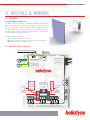
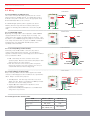
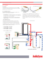
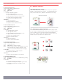
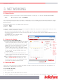
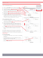
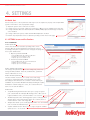
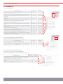
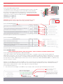
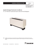
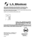
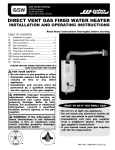
INSTALLATION GUIDE DELTA T PRO LITE CONTROL UNIT WIFI EXCELLENCE BY DESIGN TABLE OF CONTENTS 1. OVERVIEW 2 2. INSTALL & WIRING 3 3. NETWORKING 7 4. SETTINGS 9 5. MONITORING 13 6. TROUBLE 14 7. WARRANTY 16 1. OVERVIEW 1.0. For service, contact Heliodyne: (888)878-8750 1.0.0. Safety Guidelines This control conforms to the National Electric Code and is certified by the Underwriters Laboratory. Any electrical wiring or modifications to the control I/O should be performed with the power disconnected. Service should only be performed by a qualified professional. Carefully review all instructions in this manual for installation and use. Do not modify equipment under any circumstances; use only as designed. Install all components in an accessible location for servicing and maintenance. Noncompliance with these guidelines will void all warranties. Heliodyne recommends consulting an IT professional for connecting to the device and configuring network parameters. An intermediate level of knowledge in IT is required to install this controller. The Pro Lite Controllers contain battery-backed SRAM, protecting the system clock, settings and data in case of a power outage. Because the battery is only lightly used during these events, it is not user serviceable and will last the life of the control. 1.0.2. Models The Delta-T Pro Lite controller is available with a Wi-Fi signal ONLY. • DLTA 000 003 [Wi-Fi 802.11 b/g] Follow all local building codes and regulations, as well as these industry accepted guidelines and standards: BUILDING USEC, UBC, UPC, NRCA ASHRAE Solar Energy Equipment NFPA 70 National Electric Code 1.0.1. Introduction The Delta-T Pro Lite controller is designed to control basic solar thermal collector systems for use in domestic water heating. Each control contains the user interface software which can be accessed via an internet capable device and web browser. When the device is connected to an internet capable network, the controller can transmit data to the Heliodyne monitoring site for detailed data logging and system tracking. For best results, 1.0.3. Computing Requirements • PC, Mac, PDA or other internet capable device • Web Browser with JavaScript enabled • Ad-hoc network capable 1.0.4. Network Requirements for Monitoring Communication • Always on internet connection (DSL, cable, T1, etc.) • DHCP enabled network or available static IP-Address for controller • Network must allow TCP communication on port 9999 • [Wi-Fi] 802.11b/g compatible router with Open, WPA - TKIP, or WPA2 - CCMP (aka AES) encryption *WEP OR OTHER WPA/WPA2 ENCRYPTION ALGORITHMS ARE NOT SUPPORTED* 3 INSTALLATION / CONTROLLER IO 2. INSTALL & WIRING 2.0. Installation 2.0.0. Mounting the Standalone Box The Delta-T Pro Lite should be mounted on a wall indoors, away from weather and interference. Using the mounting holes on the back of the box, securely install 3 screws into mounting plane leaving 1/4” between the wall and the back of the bolt head; place control back upon screws and slide down to secure box tightly into screw pattern. A screw template is provided with this manual on page 19. An ideal installation location is: • About 5 ft. (1.5m) off the finished floor • Away from equipment and other sources of electrical interference • Out of direct sun; in a cool dry location 2.1. Controller Inputs and Outputs JP5: SHORT 2&3+ RESET BUTTON = I.P. RESET JP7 JP5 Wi-Fi JP6 1 2 3 RESET VFS - FLOW & TEMPERATURE T3 Vs S1 COLLECTOR OUT T1 STORAGE LOW T2 RPS - PRESSURE & TEMPERATURE T4 p ©2010 ON OFF INPUT POWER VOLTAGE SWITCH: 115 / 230VAC 50 - 60Hz RELAY 2: POTENTIAL FREE INTERNALLY POWERED (DEFAULT) AUTO SOLAR RELAY: POTENTIAL FREE INTERNALLY POWERED (DEFAULT) POWER INPUT NO L RELAY 2 NC NO L N L SOLAR RELAY S O L A R H O T W A T E R WIRING RELAYS FOR AVAILABLE FUNCTIONS 2.2. Wiring POWER WIRING 2.2.0. Power Wiring and LED Indication This control comes pre-wired with a grounded electric cord for plug-in operation in 115VAC systems. If a modification needs to be made to the power connection, connect the appropriate Load, Ground and Neutral wires to the connector. RED POWER LED ©2010 LOAD A red LED will light up when power is applied to the board. Likewise, when the relays have been activated, either by the controller or manually, a Green LED next to the active relay will show. NEUTRAL GREEN RELAY LED’S R2 GROUND SOLAR RELAY VOLTAGE SWITCH 2.2.1. 115/230 VAC Switch Optionally, the voltage switch can be adjusted to handle 230VAC supply (modification of the cord plug may be necessary). Use caution as this also changes the supply voltage to the relays. I.E. if the switch is set to 230VAC supply, the pumps or accessories wired to the relays must also be able to operate on 230VAC. Heliodyne packaged units come default with 115 VAC pumps, unless specifically ordered otherwise. 115VAC ©2010 230VAC SOLAR RELAY WIRING 2.2.2. Solar Relay Wiring and Functionality Solar Relay 1 has a N.O. and N.C. connection; they share a common neutral and ground connection. The Solar Relay is supplied as a wetted contact (i.e. with voltage) but can be modified to be a potential free switch. POTENTIAL FREE INTERNALLY POWERED Y: ©2010 • N.O. - Solar Relay: this is the connection for the solar operation pumps. Both the solar and the tank pumps in dual pumped systems are connected here. • N.C.: this connection can be used to power components that operate opposite to the solar operation, such as a pool controller with domestic water heating priority N.C. LOAD N.O. LOAD (SOLAR) • Timer Operation: Turn this relay on and off at a set hour INTERNALLY POWERED ©2010 during each day. Relay 2 can handle up to 20Amps resistive load such as an electric heating element. • Aquastat Operation: Operate this relay when a sensor reaches a set temperature. • Simple Differential Operation: Operate a second differential using sensors of your choice. POTENTIAL FREE NEUTRAL N.O. LOAD 2.2.4. Relay Specification Summary Table RELAY 1 (SOLAR) RELAY 2 Contact Voltage (Wetted) 115 or 230 115 or 230 Contact Type N.O. & N.C. N.O. 20A, 240VAC [N.O.] 10A, 240VAC [N.C.] 30A, 240VAC Ratings GROUND RELAY 2 WIRING 2.2.3. Relay 2 Wiring and Functionality Relay 2 has only a N.O. connection and is supplied as a wetted contact (i.e. with voltage) but can be modified to be a potential free switch. Relay 2 can have three purposes: ITEM NEUTRAL GROUND 5 SENSOR INSTALLATION AND PLACEMENT 2 . 3 . Sensor s BRASS IMMERSION WELL - 1/2”NPT 2.3.0. Types The Delta-T Pro Lite can read two types of sensors: 10kΩ Thermistors and Grundfos VFS (Vortex Flow Sensor) and RPS (Relative Pressure Sensor) sensors. 2.3.1. Thermistor Sensors We have two mounting styles of thermistors available, each suitable for different system placement: • SENS 000 001: The flattened copper lug can be attached to the sensor stud on a solar storage tank, or can be strapped to the outside of the system fluid tubing. • SENS 001 001: The sensor works in conjunction with the immersion well, and can be placed in the fluid stream for greater accuracy. SENS 000 001 SENS 001 001 The sensor leads are 24AWG Class II and carry 4VDC. Use 18-24AWG zip or bell wire to run from the sensor location to the controller. Use caution when installing to avoid wire damage. Shielded wire is not necessary. Use insulation and weatherproofing for accurate sensor readings. Install out of direct sunlight. 2.3.2. Grundfos Sensors Heliodyne recommends Grundfos VFS sensors for flow measurement. Because of the vortex principle, they are less expensive, last longer, and more accurate than pulse / paddle-wheel sensors. They also combine a temperature measurement. Model selection is based on design flow rate; we have 4 flow sizes and 1 pressure size: • • • • FLOS FLOS FLOS FLOS 010 026 053 106 000 000 000 000 [to [to [to [to SENSOR INSTALLATION T1 10.5 GPM] 26 GPM] 53 GPM] 106 GPM] • PRSS 150 000 [to 150 psi] THERMISTOR SENSORS T4 T1 RPS T2 ©2010 T GRUNDFOS SENSORS T3 T P M VFS ©2010 T3 VFS T2 T4 RPS TYPICAL CLOSED LOOP SOLAR SYSTEM S O L A R H O T W A T E R SENSORS AND MANUAL FUNCTIONS 2.3.3. Collector Sensor T1 Supplied with HPAK, and HFLO systems TYPE: 10kΩ Thermistor USE: REQUIRED FUNCTIONS: • ‘Hot’ differential operation • ‘Hot’ energy calculation • Freeze monitoring sensor for open loop • Low temperature monitor for vacation mode • Useful collector temperature monitor • Drain back system high limit monitor WARNINGS: • Isolate from ambient • Never install inside collector • Install on collector outlet header only 2.3.4. Low Tank Sensor T2 Supplied with HPAK, and HFLO systems TYPE: 10kΩ Thermistor USE: REQUIRED FUNCTIONS: • ‘Cold’ differential operation • Tank high limit monitor • Low temperature monitor for vacation mode • Single Tank Gas function monitor • Relay 2 space heating setpoint • Relay 3 operation setpoint WARNINGS: • Isolate from ambient • Ensure contact with tank wall 2.3.5. Grundfos VFS and T3 Supplied with HPAK, and HFLO systems TYPE: Vortex Flow Sensor USE: REQUIRED for energy monitoring INFO: Can be moved to measure flow anywhere in the solar system and calculate energy at that point, select sensors for cold and hot measurement in Settings FUNCTIONS: • Monitor flow rate for energy calculation • ‘Cold’ energy calculation WARNINGS: • Ensure correct VFS range is set in settings 2.3.6. Grundfos RPS and T4 TYPE: Relative Pressure Sensor / 2 x 5VDC Analog Sensing USE: OPTIONAL FUNCTIONS: • Solar system pressure monitoring • Insolation monitoring with compatible pyranometer • Electricity monitoring with compatible current transformer 2 . 4 . M a n u a l Fu n c t i o n s 2.4.0. Manual Operation of Relays The Pro Lite comes from the factory with the relays set to operate in AUTO, or controlled by the set functions. To manually disable both relays, or turn them both on, adjust the slide switch as necessary. MANUAL RELAY OPERATION ©2010 ON OFF AUTO 2.4.1. Manual Reset of Network Parameters To reset the network parameters, place the removable jumper stored on pins 1 and 2 of the JP5 location, to pins 2 and 3. With the jumper in place, firmly press the reset button and hold for approximately two seconds. Network settings and password have been reset to the defaults. Replace the jumper in its original location. NETWORK RESET JP6 JP7 JP6 JP7 1 JP5 JP5 2SEC ©2010 2 RESET JP6 JP7 RESET RESET JP6 JP7 3 JP5 JP5 JP7 1 2 3 REMOVABLE JUMPER JP6 RESET S1 JP5 7 CONNECTING TO THE CONTROLLER 3. NETWORKING 3.0. Network Overview The Heliodyne controllers use internet protocol (IP) to display information on a web page. The Pro Lite is available with Wi-Fi ONLY. • Wi-Fi [802.11 b/g wireless signal - DLTA 000 003] The controllers use Ad-Hoc networking, or computer to computer direct connect, for initial controller setup and operational use. The Pro Lite can optionally be installed on a local area network, or Infrastructure, for ease of viewing data and communication with the Heliodyne Monitoring Servers. All settings are behind a log-in. The CASE Sensitive defaults are: User Name: Admin Password: caution To begin the configuration setup of the Delta-T Pro Lite, supply the unit with power, and prepare the computer, PDA or device for connection with the controller’s default ad-hoc network: • Disconnect from any other Ethernet, WiFi, modem, or network connection and close all open browser windows. • For laptops connecting to Ethernet controls, ensure the power cable is connected as many computers disable the Ethernet port to conserve battery power. • For Windows Vista users, enable file sharing. • Make sure Javascript is enabled. 1 2 3.1. Connect to the Controller 3.1.0. Connecting to DLTA 000 002 [Wi-Fi] 1. In Ad-Hoc mode, the Wi-Fi controllers broadcast a default network name (SSID) “DTT Pro Lite WiFi” with a suffix of some combination of 4 characters (e.g. DTT Pro Lite WiFi 3C9D). These are the last 4 characters of the controller’s MAC Address, which is a unique number to every controller. This makes it easier to detect which controller you are connected to when setting up multiple controllers in close proximity. The SSID in Ad-Hoc mode can be changed as desired. 2. Connect to the appropriate Wi-Fi SSID and allow your computer to assign itself a link local address (this can take up to a minute). 3. Open a new browser window and enter the controller’s address: 169.254.148.50 in the address bar. If the Controller interface does not come up right away, refresh your browser every 5-10 seconds until it loads. 3 1. 4 2. 3. 4. 5. 6. Software Version Controller IP Address Navigation Bar System Operation, Sensor and History Data System Date and Time WiFi Signal Strength (WiFi Only), MAC Address and Software Version 5 6 3.2. Infrastructure Mode The Pro Lite can be easily setup on a network using DHCP. Heliodyne recommends an IT professional for static IP Configuration. For additional info see www.heliodyne.com/controls. 3.2.0. DLTA 000 003 [Wi-Fi] 3.2.0.0. Setup With DHCP 1. Bring up the controller’s web interface as in section 3.1.1. 2. Click on SETTINGS in the Nav Bar; you will be prompted for a user name and password, enter the defaults unless you have changed it. S O L A R H O T W A T E R NETWORK SETUP / SETTINGS 3.2.0.0. Setup With DHCP (Continued) 3. 4. 5. 6. 7. 8. 9. Click on the NETWORK Bar near the bottom of the page. In the Infrastructure Box, click on the Set Active radio button. Select the ‘Use DHCP’ box. Set which form of encryption your router is using. Enter the name of the WiFi network you wish to connect to - this is CASE Sensitive. Enter and re-enter in the passphrase for your WiFi network, also CASE Sensitive. Hit ‘Update Network Settings’ and close your browser window. Use the Delta-T Pro Discovery Tool to find the Controller and click on ‘Open Web Interface’ to view it in your web browser. This program is available for download at www.heliodyne.com/controls. 3.2.0.1. Setup With Static IP Address 1. Follow steps 1-4 above in section 3.2.0.1. 2. Uncheck the ‘Use DHCP’ box if it is selected (the IP Address and network numbers will display). 3. Follow steps 6-8 above in section 3.2.0.1. 4. Enter in the appropriate settings for your static IP Address and 5. network settings. Note that any static IP Address selected should be available and outside the assigning range of the DHCP server / router. Hit ‘Update Network Settings’ and close your browser window. Open a new browser window and navigate to the Static IP just entered. If the network settings were entered incorrectly or incompatible with the network, the controller will reset itself within one minute’s time to transmit again in Ad-Hoc mode with the default SSID and IP Address of 169.254.148.50. 3.2.1. Wi-Fi Ad-Hoc Mode • To change back to Wi-Fi Ad-Hoc mode, Set Active in the SETTINGS > Network tab. • The network parameters are reset to the defaults and cannot be changed in this mode, except for the SSID. • Once back in Ad-Hoc transmitting mode, the Ad-Hoc SSID can be renamed. • Save the settings to take effect. 9 CHANGING CONTROLLER OPERATION SETTINGS 4. SETTINGS 4.0. Quick Start For fast setup, here is a list of parameters that may need to be adjusted to properly control simple DHW systems. Remember to save any adjusted settings. 1. Adjust the system clock to reflect the local time. 2. If using an open loop system, change the system type to Open Loop for enabling freeze protection. 3. If using a Grundfos VFS other than installed in an HPAK, HFLO, adjust the flow range to match the sensor installed. 4. If using a drain back system, enable the Drain Back Operation checkbox. 5. Rename any temperature sensors as desired by clicking on them in the home page. 4.1. SETTINGS Screens and Pro Functions 4.1.0. SYSTEM Bar 4.1.0.0. System Box The Pro Lite has two user selectable operating modes. Each activates different operation algorithms and should be selected accordingly. Every time a system has been changed, all settings are reset to their default values. 1. Open Loop Residential DHW • Presets Differentials: On at 9°F and Off at 4°F • Enables freeze recirculation at 35°F • Adjusts Glycol Concentration to 0% 2. Closed Loop Residential DHW • Presets Differentials: On at 18°F and Off at 5°F • Disables freeze recirculation • Adjusts Glycol Concentration to 50% 4.1.0.1. Settings Login Password This changes the password to log in to the settings only, it does not change the WiFi password. Enter the password twice, passwords must be 20 characters or less. 4.1.0.2. 24 Hour System Clock The time and date need to be set to stamp sensor and energy correctly for communication with our monitoring servers. Note that setting the time will cause the controller to restart and may be unavailable in your browser window immediately following the update. Provided the network settings are correct, the controller will come back on to the same IP Address. 4.1.0.3. Links • • • • ‘Setup Monitoring Communication’ takes you to a page to register your controller with the Heliodyne Monitoring Service. Once you are registered with the service, this link is hidden. See section 5. ‘Download System Sensor and Energy Data’ opens a new page which displays all the current saved history data in the controller, about 1 month’s worth of sensor and energy data. ‘Relay Control Panel’ opens a new page within which one can manually turn on and off the individual relays. ‘Update Software Version’ directs you to a page to begin the software update process. See Section 6. S O L A R H O T W A T E R CHANGING CONTROLLER OPERATION SETTINGS 4.1.1. OPERATION Bar 4.1.1.0. Solar Relay Box DEFAULT SETTING LIMIT The minimum Differential (Value of [T1 minus T2], or if T3 is installed and the average is used [T1 minus the average of T2 & T3] ), to turn Relay 1 ON from OFF FUNCTION DESCRIPTION 18°F [CL], 9 [OL] 2°F V 100°F Check this box to use the tank average in Differential and High Limit Operation (Pro Models Only) OFF ON / OFF During Relay 1 operation, the maximum Differential the system can exhibit in order for Relay 1 to turn back OFF 5°F [CL], 4 [OL] 0°F V < On Diff. The percentage of Dowfrost HD propylene glycol in the heat transfer fluid to be used in the energy calculation 50% [CL], 0 [OL] 0% V 70% The limit Value T2, at which the solar relay will turn OFF even with a satisfactory differential. NOT TO BE RELIED UPON AS A SAFETY LIMIT OR PRIMARY LIMIT CONTROL. 160°F 80°F V 200°F ON ON / OFF 82°F [CL], 80 [OL] 50°F V 200°F 120°F 80°F V 200°F OFF ON / OFF 35°F [OL Only] 33°F V 80°F OFF (CL) ON / OFF OFF ON / OFF DEFAULT SETTING LIMIT Check this box to use the Tank High Limit Function The minimum Value T1 must be greater than for the differential function to begin monitoring the differential Uses the cool nighttime collectors to deplete energy from the storage. Set the minimum T2 Value to cool the tank down to. Check this box to use the Vacation Mode function If the selected system on the SETTINGS > SYSTEM bar is Open Loop, recirculates warm storage water through the collector loop when this value is greater than T1. Check this box to use Freeze recirculation when the set system is not Open Loop Check this box when operating a Drain Back system to prevent thermal shock when the Differential is greater than 100°F and the Solar Relay, Relay 1, is off. 4.1.1.3. Relay Two Operation: Timer Relay Operation Relay two can be used to operate on a time setting. FUNCTION DESCRIPTION Check this box if using R2 as a timer relay. Relay capacity is 30A, 240VAC. OFF ON / OFF At the top of this hour Value, i.e. 8:00 or 8 AM, R2 will shut OFF. The clock is a 24-hour clock. 8:00 0 V 23 At the top of this hour Value, i.e. 17:00 or 5 PM, R2 will turn ON. The clock is a 24-hour clock. 17:00 0 V 23 4.1.1.4. Relay Two Operation: Aquastat Operation Relay Two can also be operated in Aquastat Mode. Check the ‘Aquastat Operation’ button to enable this function. FUNCTION DESCRIPTION DEFAULT SETTING LIMIT The temperature the selected sensor must exhibit to turn R2 ON. If this temperature is less than the R2 OFF temp, R2 will be ON in between the OFF and ON temp; otherwise, it will be ON above the R2 ON temp, and turn back off at the R2 OFF temp 160°F 50°F V 200°F The temperature the selected sensor must exhibit to turn R2 OFF. See above if R2 OFF > R2 ON. 150°F 50°F V 200°F T2 T1 v T4 The installed sensor for reading the ON and OFF values set above. 11 CHANGING CONTROLLER OPERATION SETTINGS 4.1.1.5. Relay Two Operation: Simple Differential Operation Relay Two can be operated using a secondary differential with a high limit, and optionally function conditionally based on the Solar differential or another sensor. DEFAULT SETTING LIMIT HOT temperature sensor for the differential equation (ΔT=Hot Sensor - Cold Sensor) FUNCTION DESCRIPTION T1 T1 V T4 COLD temperature sensor for the differential equation (ΔT=Hot Sensor - Cold Sensor) T2 T1 V T4 The minimum Differential (ΔT=Hot Sensor - Cold Sensor) to turn Relay 2 ON from OFF 18°F 2°F V 100°F During Relay 2 operation, the maximum Differential the system can exhibit in order for Relay 2 to turn back OFF 5°F 0°F V < On Diff. 160°F 80°F V 200°F ON ON / OFF T1, 160°F T1 v T4 50°F V 200°F The limit Value COLD sensor at which R2 will turn OFF even with a satisfactory differential. NOT TO BE RELIED UPON AS A SAFETY LIMIT OR PRIMARY LIMIT CONTROL. Check this box to use the R2 high limit function Choose this option to operate Simple Differential only when the Solar Relay is ON Choose this option to operate Simple Differential only when the Solar Relay is OFF due to the Solar Tank greater than the high limit value (T2 or the Average of T2 & T3 if installed and Use Average is selected) Choose this option to operate Simple Differential when the selected sensor is hotter or colder than the set temperature. Choose this option to operate Simple Differential all the time 4.1.2. SENSORS AND METERING Bar 4.1.2.0. System Metering Box The Delta-T Pro Lite can be fitted with many different inputs above the normal temperature sensors, including an electronic pressure sensor, pyranometer or current transformers. In addition, the energy calculation algorithm can be adjusted for the installed parameters. METER DESCRIPTION Select if a Grundfos VFS flow and temperature sensor is installed DEFAULT SETTING LIMIT ON ON / OFF Set the flow Range for the Grundfos VFS; this is the flow range in LPM. HPAK / HFLO Pro and HCOM’s have the default’s preset. If a sensor is purchased separately, the range is printed on the packaging. HPAK/HFLO 2-40 HCOM 20 - 400 The Pro Lite is only capable of reading a Grundfos VFS sensor and therefore will use it for the Energy calculation - - Select which sensor will be used for the HOT sensor in the System Energy Calculation. FOR GREATEST ACCURACY, SELECT TWO SENSORS OF THE SAME TYPE (I.E. Thermistors T1&T2, or Grundfos T3 & T4) T1 T1 v T4 Select which sensor will be used for the COLD sensor in the System Energy Calculation. FOR GREATEST ACCURACY, SELECT TWO SENSORS OF THE SAME TYPE (I.E. Thermistors T1&T2, or Grundfos T3 & T4) T3 T1 v T4 OFF ON / OFF Select whether a Grundfos RPS pressure sensor is installed (0 - 150PSI) MIN: 2-40 MAX: 20-400 S O L A R H O T W A T E R SENSORS / SOFTWARE UPDATE 4.1.2.0. System Metering Box (Continued) The ‘Grundfos Pressure’ signals can be for two alternate purposes in place of the RPS sensor (Pressure and T7): measuring an electric circuit with a current transformer (CT) such as a main supply and electric tank element, or monitoring insolation with a pyranometer. Two signals can be read simultaneously. The Delta-T Pro electrical requirements are below. At right is the PCB signal layout. Power Supply 5VDC Signal Reading Range 0-5VDC +5VDC GND S1 S2 1 2 3 4 Grundfos Flow Grundfos Pressure IMPORTANT: Reversing polarity or going outside of signal ranges will damage circuits. Contact Heliodyne for connector with 12” wire leads, part number: 21816. 4.1.2.1. Electricity Monitoring Box FUNCTION DESCRIPTION DEFAULT SETTING LIMIT 240VAC 10 V 500VAC 50A 10, 20, 50, 100, 150, 200A 240VAC 10 V 500VAC This is the CT’s full scale value (when the controller reads 5VDC, the CT is at full scale) 50A 10, 20, 50, 100, 150, 200A This is the power frequency (60Hz is standard in USA) 60Hz 40 - 70Hz Main Circuit Volts AC is the nominal Voltage the CT connected to S1 This is the CT’s full scale value (when the controller reads 5VDC, the CT is at full scale) Tank Circuit Volts AC is the nominal Voltage the CT connected to S2 Contact Heliodyne for information about compatible CT’s. 4.1.2.2. Insolation Monitoring Box DEFAULT SETTING LIMIT Select to enable insolation monitoring on Pin 3 (S1) FUNCTION DESCRIPTION - - Select to enable insolation monitoring on Pin 4 (S1) - - Select to read dual pyranometers, on Pin 3 (S1) AND Pin 4. - - 1.0 1000.0 Calibration constant of the installed pyranometer. This is the multiplier the controller will use to turn the read voltage into insolation. Contact Heliodyne for information about compatible pyranometers. 4.2.0. SOFTWARE UPDATE CAUTION: SOFTWARE UPDATES MAY RESET SETTINGS BACK TO DEFAULTS. VERIFY ALL SETTINGS ARE AS REQUIRED FOLLOWING AN UPDATE. 4.1.2.0. Software Update through Web Browser - WiFi Controllers ONLY The Pro WiFi controllers can be easily updated through the web browser. To upgrade, ensure you have the latest software from www.heliodyne.com/controls. There are several versions of software on the webpage, for WiFi Pro’s, WiFi Lite’s and Ethernet, so it is crucial to save the version that goes with your model. The software is typically saved in a compressed folder, with the extension .ZIP. Uncompress the folder and there will be a .BIN (binary) file and the release notes in a .TXT file inside. READ THE RELEASE NOTES. The .BIN file is the actual file used by the controller. Navigate to the SETTINGS page under the SYSTEM box. Click on the link that says ‘Update Software Version.’ A window will pop up and ask for the user and password, these are the same used to enter into the settings as described in section 3.0. The default user name is ‘Admin’ and the default password is ‘caution’. Once logged in the page below displays. 4.1.2.0.0. Web Browser Update Process 1. Select ‘Choose File’ and navigate to the .BIN file on your computer. Once selected the path should display next to ‘Upload’. This is the version the controller is currently operating with. This is the last version of software that was loaded into storage (not operating.) For new controllers this may say ‘No upgradable firmware has been loaded.’ 1 2 13 SOFTWARE UPDATE / MONITORING 2. Hit ‘Upload’. The controller will download the file you selected into storage. This can take a minute or two for the controller to save the complete file. 3. After the controller has downloaded the file the browser will display the successfull upload page showing the size, hardware and version. This is just a confirmation that the file downloaded has been saved into storage and is compatible with the controller; the software still needs to be installed. IMPORTANT: If the file was damaged, incompatible or the transfer interrupted you will see an error below the ‘Firmware uploaded successfully’ in green. You will need to repeat steps 1-3. 4. After a successful download, click ‘Install’ to install the newly downloaded file into the controller’s operating memory. The controller will become unresponsive at this point and you may see a connection error in your browser. DO NOT UNPLUG THE CONTROLLER. It can take up to two minutes to install the new software, restart, and come back into operation mode. If the controller is being upgraded from a very old version of software, it is likely it will return to Ad-Hoc mode and need to be set up again on the network (if using Infrastructure Mode). 5. After the controller has restarted and is operating once again, check the settings to ensure they are adjusted as necessary. 5. MONITORING 5.0. Overview The Controller has two types of monitoring, the built in or Local Monitoring that is stored in the controller’s memory, and the Heliodyne Web Monitoring service. The Local Monitoring is limited because of the size of the controller’s memory. When the controller is connected to a network with an internet connection, it communicates with the Web Monitoring service, which is available for viewing performance data and settings from the WWW; anywhere in the world. It is also possible to change settings, add site pictures and more. 5.1. Local Monitoring 5.1.0. ENERGY Page In addition to the sensor data graphs on the home page, the controller also displays the last 30 days, and 12 months of accumulated energy data. More in depth monitoring is provided on the Heliodyne Web Monitoring service. At this point all numbers are in imperial units. 5.1.1. SETTINGS Page - Download System Sensor and History Data This page displays all the current saved sensor and energy history data for the controller. This is the same data that is sent to the Web Service. Currently the Pro Controllers can hold about 30Days worth of sensor history data. This data is taken as an average of sensor readings over a complete 10Minute period. (Sensor readings are taken every second). This data can be saved as a text file and imported into a numbers program. With the browser page open, select all the data and paste into a text editing program (Notepad for PC’s, Text.app for Mac’s). Filter the data by selecting ‘Comma Delimited’ to get all the numbers in the correct columns. 5.2. Heliodyne Web Monitoring (http://monitoring.heliodyne.com) 5.2.0. Monitoring Setup Set the controller in Infrastructure Mode as in section 3. Navigate to the SETTINGS home page, under the SYSTEM bar and click on the ‘Setup System Monitoring’ link. You will be directed to an email form on the Heliodyne website. Fill out all the required fields and send it. If you are installing multiple controllers for a single energy producing system, put the MAC address for each controller so Heliodyne can consolidate the users and data for those controllers. Tip: when you click on the link, it saves the controller’s MAC Address in the browser address bar, for easy copy and paste into the email form. Heliodyne will register your controller and send all associated parties an email on login information within one business day. S O L A R H O T W A T E R TESTING / NETWORK TROUBLE 6. TROUBLE 6.0. Delta-T Pro Lite Testing and Troubleshooting More in-depth knowledge is available at www.heliodyne.com/controls. Before contacting Heliodyne tech support, run through this entire section to see if it solves the problem. If the issue cannot be resolved by these tests and common problems, their answers will give Heliodyne a better idea of what the issue might be. 6.0.0. Testing TEST NAME METHOD OUTCOME Supply the controller with power If there is a red LED near the thermistor sensor inputs, the control has power. If there is no red LED, check the fuse for continuity. If the fuse is bad, replace with a similar 100mA fuse. On / Off Test Manually turn the relays on or off Review section 2.4.4. Turn the relays on; each relay should have a green LED lit up next to it. When lit, test the voltage at the NO contact to see if 120VAC (or 240VAC if switched) is supplied. Turn the relays off; no green LEDs next to the relays should be lit. Test the NO contacts to be sure there is no voltage supplied when off Basic Sensor Test Short or Open sensors A sensor short signals to the controller a high temperature of around 350°F, an open signals a very low temperature of around -90°F. Measure the sensor resistance Disconnect the sensor from the control to prevent any controller feedback. Using a voltmeter set to read Ω, or Ohms, measure the resistance of the installed sensor. Check this table to see if the measured values correspond to the expected values. Bad values can mean the connecting wires or the sensor itself. If a bad sensor is suspected, check the sensor at the 6” factory leads. Power Test Sensor Operational Test Basic Function Test Short or Open sensors (assuming no high limit or other extreme conditions) °F Ω Infinity 40 104 5,326 0 32 32,630 50 122 3,601 10 50 19,890 60 140 2,487 20 68 12,490 70 158 1,751 25 77 10,000 80 176 1,255 30 86 8,057 100 212 680 °C OPEN SHORT 0 Test the differential setting & collector: short T1; the pumps should turn on Test the differential setting & storage: open T2; when T1 is above the Usable Collector Temperature set in the SETTINGS; the pumps should turn on Test the freeze protection in open loop mode: open T1, the pumps should turn on 6.0.1. Troubleshooting Network Issues ISSUE • [Wi-Fi] Can’t connect to the controller • Connected, but can’t view the web interface POSSIBLE CAUSE SOLUTION Connected to another Wi-Fi or Ethernet network When the controller is in Ad-Hoc mode, as shipped from the factory, to connect to the “DTT PRO WIFI” network, the computing device cannot be connected to any other network. The device must connect only to the controller’s network. PC: Computing device driver issue The best way to connect to a Wi-Fi controller is to use the Operating System’s (I.E. Vista, or XP’s) connection feature, rather than the device’s Wi-Fi card driver software (usually done in the task bar). To connect via the OS, go: Start > Control Panel > Network Connections > Local Area Network and select the network to connect to. Computing device has not had time to resolve the IP addresses Depending on the speed of the device, it can take up to 1 minute for the device to allow communication to the Pro. Close any open browser windows, and reopen once connected. Incorrect IP Address entered If the controller’s settings have not been changed, use the default IP: 169.254.145.50. If that does not solve the issue, review section 2.4.5. and reset the control to the defaults. Close the web browser window, open a new window, try the default settings. 15 NETWORK / OPERATION TROUBLE 6.0.1. Troubleshooting Network Issues Continued ISSUE POSSIBLE CAUSE [Wi-Fi] Router incompatible The Wi-Fi router must be able to handle 802.11 b/g communication. The encryption MUST be either Open, WPA - TKIP, or WPA2 - AES. If trouble exists with the encryption, set the router to filter MAC addresses in open communication and add all the MAC addresses destined for the network. See 4.1.0. for the controller’s MAC. Incorrect network settings Consult an IT professional or system administrator to ensure the correct parameters are set in the controller for use on the network. If the settings were changed, the controller will be available at the new saved IP Address rather than the default. Credentials were entered incorrectly The User ID and password are case sensitive, and must be entered exactly as the defaults or saved value. Password was changed If the password was changed and forgotten, follow section 2.4.5. to reset to the defaults. This will also reset any changed network parameters. • Can’t connect to the controller on a network • Can’t get into the settings SOLUTION 6.0.2. Troubleshooting Operation ISSUE • Not Enough Hot Water • Bad or no sensor readings in the control software POSSIBLE CAUSE Incorrect piping connections or dip tube lengths Controller doesn’t turn pumps on Check the sensors and ensure they are contacting the piping or tank sufficiently and they are well insulated from the ambient temperatures to provide accurate readings. Improper wiring or loose connections Ensure all the connections are placed in the proper input area i.e. the low tank sensor actually does connect to the controller at T2; wire colors are oriented in the proper terminals (Specifically Grundfos VFS and RPS sensors), the connectors are firmly connected and pressed all the way in or down, and all connections are metal to metal, no plastic or wire insulation can interfere for proper operation. Bad sensors or wiring Use the Sensor Operational Test in 6.0.0. to determine if the thermistors are sending an appropriate reading to the controller. Sensor not installed If the sensor reads a very low temperature in the range of -80°F to -110°F, the control is not receiving any signal from that sensor, i.e. it is not installed or installed properly. Controller is in OFF position Review section 2.4.4. If there is no jumper in the correct location, use the jumper located at JP5 for resetting the network parameters (No jumper at JP5 has no affect on the network parameters). No electricity to pump Check the pump wiring to ensure pump(s) have correct wires at the terminals (i.e. white goes to N, green to ground, etc) and at the relay contacts. Measure voltage at the relay contact to determine if voltage is supplied. Ensure the unit is plugged in and the controller voltage switch is set to provide the correct voltage. Check the fuse to make sure it has not blown. Differentials are set too high Adjust the differentials back to the defaults as described in section 4.2.1. Loose or bad contact Clean contacts and firmly place connections, ensure metal to metal contact. Bad sensors or wiring Use the Sensor Operational Test in 6.0.0. to determine if the thermistors are sending an appropriate reading to the controller. Minimal solar energy available This can be normal operation in fall, winter and spring depending on the collector to storage ratio. To alleviate in these months: • Set a higher ON differential • Increase the usable collector temperature For open loop systems, the freeze protection may be set too high Decrease the temperature at which the controller will recirculate hot storage water to prevent freezing; see section 4.2.1. to reset the default value. Bad sensors or wiring Use the Sensor Operational Test in 6.0.0. to determine if the thermistors are sending an appropriate reading to the controller. • Pump does not start • Pump cycles on and off • Pump runs continuously SOLUTION Check the heat transfer appliance tank connections and ensure the hot goes into the top of the tank with a short or no dip tube, and the cold goes into the bottom of the tank, or the top with a along diptube. Ensure the hot out of the tank to the fixtures is not shared with the solar equipment. Controller is in ON position Review section 2.4.4. and remove any unnecessary jumpers. Usable Collector Temperature is set too low Increase the temperature at which the collector must reach to begin monitoring the differential function; see section 4.2.1. to reset the default, or increase the value. Bad sensors or wiring Use the Sensor Operational Test in 6.0.0. to determine if the thermistors are sending an appropriate reading to the controller. S O L A R H O T W A T E R WARRANTY 7. WARRANTY HELIODYNE, shall provide a warranty for defects in compliance with the purchased goods delivered after 3/1/2009. This warranty applies to the first retail buyer and to any subsequent owners. Product shall be free from defects in material and workmanship, malfunctions and failure to perform, under normal use, service and maintenance, provided that said products have been installed in accordance with HELIODYNE’s Installation Instructions. The warranty term for each product shall begin on the date of installation and remain active for the period of time as specified and applicable for each individual product. The HCOM, HPAK, HFLO, HPAS Products and their variants. • Five (5) year limited warranty (parts only, no labor, no shipping) from date of installation when installed with HELIODYNE Collectors. • Three (3) year limited warranty (parts only, no labor, no shipping) on Integrated Electronics (such as controller, pumps, sensors, etc.) • In the event that the Product is installed with another brand of collector, or any equipment other than HELIODYNE collectors, then the period of time shall be one (1) year from date of installation for Product and Electronics. The GOBI Collectors and their variants. • Ten (10) year limited warranty (parts only, no labor, no shipping) from date of installation. The DELTA-T Products and their variants. • Three (3) year limited warranty (parts only, no labor, no shipping) from the date of installation. In the event that evidence cannot be provided to indicate the date of installation, then the warranty period shall begin on the date the product was manufactured. Objects are warranted at HELIODYNE’s discretion by repair of the object of purchase or replacement of defective parts, exchange or reduction of price. The right of the contractor to convert objects is ceded by common consent. Replaced parts become the property of HELIODYNE. Wages and costs spent on shipping, installation and disassembly must be covered by the client. This provision similarly applies to all warranty agreements. It is at HELIODYNE’s discretion to replace defective goods with similar, faultless goods. In this case, any rights to cancel the agreement cease. The client expressly waives the right for it and its legal successors to assert claims for damages or loss of profit (including without limitation special, indirect, loss of use, contingent, or consequential damages) due to defects or nonconformity in the purchased good. The warranty set forth above constitutes the sole and exclusive remedy against HELIODYNE for the furnishing of any nonconforming or defective goods. THE ABOVE WARRANTY IS EXPRESSLY IN LIEU OF ALL OTHER WARRANTIES, EXPRESS OR IMPLIED, INCLUDING WITHOUT LIMITATION ANY WARRANTY AS TO MERCHANTABILITY OR FITNESS FOR A PARTICULAR USE OR PURPOSE. If the Product contains a defect that cannot be repaired after a reasonable number of attempts to do so, you, the buyer, may elect either a refund of its purchase price, or a replacement without charge. A replacement may consist of a new or factory rebuilt product of at least the same quality. A new warranty shall apply to any replacement. Claims on warranty will only be admitted and considered if they are announced in writing immediately after the defect was first noticed. Oral communication or communication by telephone is not sufficient. To obtain service on the Product, notify Heliodyne Customer Service by email at [email protected], or by letter to 4910 Seaport Ave., Richmond, CA, 94804. Provide proof of purchase and date. Should service be requested and no defect found in the Product, then a reasonable charge will be made for the service. In no event shall HELIODYNE be liable for the following: • Conditions resulting from a defect in a component or part that does not make up the HELIODYNE Product. • Conditions resulting from a significant departure from Heliodyne’s Installation Instructions. • Conditions resulting from any misuse, abuse, negligence, weather damage, accident or alteration. • Consequential damages such as: damage to your property, loss of time, inconvenience or loss of use of the Product or any incidental expenses resulting from any breach of the express warranty. Conditions that may occur in the normal operation of the Product shall not be invoked by HELIODYNE to reduce or defeat the coverage of this warranty. HELIODYNE’s liability under this warranty shall be in lieu of all warranties of fitness and in lieu of all warranties of merchantability. Heliodyne shall not be liable for any incidental or consequential damages covered by a defective product. The maximum liability under this warranty shall not exceed the contract price of the Product. Some states do not allow the exclusion or limitations of incidental or consequential damages, and some states do not allow limitations on implied warranties, such as that of fitness and of merchantability. Therefore the above exclusions and limitations do not apply to you. The warranty excludes damage caused by force majeure and malfunction that are due to improper assembly, and/or product installation. HELIODYNE is not liable for possible costs resulting from defects. Glass breakage in collectors is specifically excluded. In order for HELIODYNE to accept liability: • Installation must have been carried out by a licensed specialized company (heating contractor or plumber) following the version of installation instructions in force; • HELIODYNE or its representative was given the opportunity to check complaints on site immediately after any defect occurred; • Confirmation exists that the system was commissioned properly and that the system was checked and maintenance was performed annually by a specialized company licensed for this purpose. The warranty agreed by HELIODYNE is only valid for their clients. This warranty gives you specific legal rights, and you may also have other rights, which vary from state to state. Unless otherwise explicitly agreed in writing, it is understood that these are the only written warranties given by HELIODYNE, and HELIODYNE neither assumes nor authorizes anyone to assume for it any other obligation or liability in connection with the Product. 17 MOUNTING TEMPLATE 4.00” 4.25” 7.00” 2.00” 6.50” SCALE = 1:1 S O L A R H O T W A T E R This Page Intentionally Blank 19 This Page Intentionally Blank S O L A R H O T W A T E R Heliodyne, Inc. • 4910 Seaport Avenue • Richmond, CA 94804 T: 510.237.9614 • F: 510.237.7018 www.heliodyne.com Sales Inquiries: [email protected] Information and Support: [email protected]