1
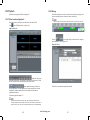
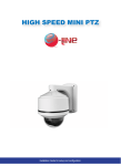
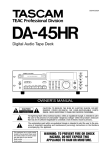
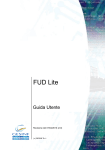
NETWORK VIDEO RECORDER Plug In Auto Detect Rercord 01.BSM.15.0009501 Product Made in China under ISO9001 & ISO1400 standards Manual Printed in China v1.0 NVR Software Guide for setup and configuration. Contents About this document About this document .................................................................................................. 2 Purpose This document is for Network Video Recorders, including the product features, hardware installation, network access, network configuration, daily maintenance, and troubleshooting. Contents ........................................................................................................................ 3 1 Preface ........................................................................................................................ 5 1.1 Important note ................................................................................................................ 5 1.2 About this manual........................................................................................................... 5 1.3 Check the installation environment ................................................................................ 6 Intended Audience This document is intended for: 2 Specification ............................................................................................................. 7 Technical support engineer Maintenance engineer 3 Operation instruction .............................................................................................. 9 3.1 Front panel description ................................................................................................... 9 3.2 Rear panel description .................................................................................................. 10 3.3 First boot ....................................................................................................................... 11 3.4 Shutdown ..................................................................................................................... 12 3.5 Displayer resolution adjustment ................................................................................... 12 3.6 Add Network cameras .................................................................................................. 14 3.7 Login ............................................................................................................................ 15 3.8 Web access ................................................................................................................... 16 Symbol Conventions This symbol may be founded in this document are defined as follows: Symbol description Alerts you to a high risk hazard that could, if not avoided. Alerts you to a medium or low hazard that could, if not avoid, result in moderate or minor in injury. 4 Quick configuration .............................................................................................. 18 Alerts you to a potentially hazard situation that could, if not avoid, result in damage, data loss, performance deterioration, or unanticipated results. 5 Live video ................................................................................................................ 24 6 Playback................................................................................................................... 28 6.1 Recording playback ...................................................................................................... 28 6.2 Recording backup ......................................................................................................... 29 Provide a tip that may help you solve a problem or save time. 7 Alarm searching ..................................................................................................... 33 Provides additional information to emphasize or supplement important points in the main text. 8 Setup ........................................................................................................................ 35 8.1 NVR setup .................................................................................................................... 35 8.2 Camera management .................................................................................................... 48 Special Notices When using video surveillance products, comply with applicable statutory and regulatory requirement to enable and maintain legal surveillance device. It is illegal for company or person to install surveillance devices in an office to monitor employees outside scope of local law, or use surveillance devices to invade other people’s privacy with illegal purposes. -2- 9 Web Browser Access NVR ................................................................................... 49 eLineTechnology.com 9.1 Login ............................................................................................................................ 49 9.2 Operation Read............................................................................................................. 50 9.3 Live Video .................................................................................................................... 52 9.4 Playback ....................................................................................................................... 53 -3- 9.5 Alarm Search ................................................................................................................ 55 9.6 NVR setup .................................................................................................................... 55 9.7 Network Camera setup ................................................................................................. 56 1 Preface 10 NVMS Access NVR ............................................................................................. 57 10.1 Start and Run .............................................................................................................. 57 10.2 Login .......................................................................................................................... 57 10.3 System main interface ................................................................................................ 58 10.4 NVR management ...................................................................................................... 58 10.5 Playback ..................................................................................................................... 66 1.1 Important note Thank you for choosing our Network Video Recorder (NVR). Please read this user manual carefully before using NVR. Network Video Recorder (NVR) is a complicated system equipment. For avoid any fault caused by installation, debugging, operation and environment causes, please read below important note: Read this manual carefully before installation. In view of the different brands and models of hard disk in the current market, we recommend using SEAGATE and WESTERN Digital with high stability and high performance-price ratio. Never open the device cover and dissemble the device by nonprofessional person, otherwise may cause damaging and electric shocking. Video data lost caused by installation, configuration, improper operations, and hard disk error is born by the buyer. 1.2 About this manual Before you use this manual, please read below declarations carefully: -4- eLineTechnology.com This manual is intended for NVR user. This manual content is suitable for NVR. This manual gives example to explain NVR operation details and performance index. Before using NVR, please read this manual carefully and follow the steps to install and use. For any questions during using the NVR, contact service center. The device may be upgraded without prior notice. -5- 1.3 Check the installation environment 2 Specification Installation environment Before installing the device, checking the environment according to the Table 1-1 Installation environment check items Check item standard Moisture-resistant The relative environment humidity must be in the range from 5% to 95%. If the humidity is higher than 95%, a dehumidifier must be installed, such as an air conditioner with the dehumidification function or a dedicated. Dehumidifier. In addition, water seepage, water dropping, and dew forming and not allowed. Dustproof Lightproof If the office block is near the source of dust, such as the colliery, country install for the offices, and anti-burglary and fireproofing doors must be installed for the equipment room. The device must be installed in the environment that is not shined by a strong light, delaying the aging of the device enclosure. System CPU SOC (System-on-chip) Operating system Embedded Linux 2.6 Features Watchdog technology, automatic fault reset; quickly configure, easy to use Video Record 4 x 1080P Network Camera (average stream 6Mbps) Or 6-channel 720P Network Camera (average stream 4Mbps) Or 12-channel D1 Network Camera (average stream 2Mbps) Largest video capacity does not exceed the total bandwidth of 24Mbps Ability to decode H.264 (ISO / IEC 14496-10) high profile 4.2 Can decode 1080P video streaming Real-time video Single screen: 1x1080P/720P/D1 Four pictures: 4xD1 Six screen: 6xD1 Graphical interface Resolution VGA: resolution including 1024x768/1280x1024/1600x1200 HDMI: Resolution including 1920x1080P/1280x720P Installation notice During the installation, please notice: NVR power input voltage is DC12V(±5%). The supply voltage must meet the input voltage, can’t be higher or lower. NVR installation should be kept horizontal. NVR installation should avoid direct sunlight, and keep away from heat and high temperature environment. Make sure connects NVR with other equipment’s normally. Install the Hard Disk when use NVR first time. NVR can automatically identify the hard drive capacity, support current market mainly models. But for NVR work stable we advise to use good brand hard disk. Others Please use a soft and dry cloth to clean NVR, do not use chemical solvents. Don’t put other things on NVR. NVR is standard of electromagnetic radiation, no harm to human body. -6- Storage HDD eLineTechnology.com Two external-swappable hard disk , maximum 2x2TB hard drive supported -7- Recording time D1: stream 2 Mbit / s 2M x 3600s / 8 = 900MB / H (1 hour using 900MB of disk space) 720P: stream 4Mbit / s, 4M x 3600s / 8 = 1.8GB / H 1080P: Maximum stream 6Mbit / s, 6M x 3600s / 8 = 2.7GB / H 2 2T Hard Drive: 4 x 1080P can be kept for 15 days; 6 x 720P can be kept for 15 days; 12-channel D1 can be kept for 15 days 3 Operation instruction 3.1 Front panel description Figure 3-1 shows the front panel of the Network Video recorders. Table 3-1 shows the description of front panel. Audio Audio output Line Out, Audio interface output from the rear panel. Audio formats G711,G723.1,8K,16bits Sampling Figure 3-1 Front panel Network Transmission control Embedded network bandwidth adaptive flow control technology. Web Webserver supported with Flash technology for and popular browsers in real-time monitoring and video playback, and system configuration. Network protocol RTP/RTCP, TCP/UDP, HTTP, DHCP, DNS Client Characteristic Temperature Ambient temperature: -10 ° C -45 ° C, using industrial grade microprocessor, intelligent heating and cooling Humidity: 20% to 80% Power consumption With two 2T hard drive to increase 18W low-power design, the motherboard's maximum power consumption of 6W; Power input DC 12V±5% 5A Thermal The main chip heat sink, plus intelligent temperature controlled fans. Size Chassis:220mm x 150mm x 100mm(L x W x H) -8- eLineTechnology.com Table 3-1 Front panel description No. Name Description 1 HDD Enclosure For fixed hard 2 HDD LED Hard normal solid red status. 3 The key to open / power indicator Open, close, NVR, NVR is turned on the power light is solid red power light flashes red NVR Close. 4 Network indicator Flashing green network connection is normal. 5 Alarm indicator Reserved for future use. 6 USB interface External mouse, keyboard, mobile hard disk. -9- 3.2 Rear panel description 3.3 First boot Figure 3-2 shows the rear panel of the Network Video recorders. Table 3-2 shows the interface of rear panel. Figure 3-2 Rear panel Make sure that the right of access to power NVR. Ensure correct display HDMI or VGA interface connection. If the front panel of the power indicator lamp does not flash please plug in the power cable .Enable the power switch, NVR start running. If the front panel power indicator lamp flashing Red light, please put the switch at front panel to start device. After the device starts, the power light is solid red device starts after the self-test, and the test results are displayed on the screen. Show in Figure 3-3. Entire boot process takes about two minutes. Figure 3-3 Device power on Table 3-2 Real panel description No. Name Description Cooling fan Start automatically when the temperature is too high. 2 Power switch Turn on or turn off the power. 3 Power Interface DV12V, 5A power. 4 Audio output 3.5mm Mono audio. 5 HDMI output HDMI video output interface. 6 VGA output VGA DB15 video output interface. 7 RST button Restores the factory default settings. 5 second holds. 8 Network Interface RJ45 100Mbps network interface. 1 -10- When an exception occurs when the device self-test, this interface will stay in the lower right of the screen, you can choose to continue or shutdown. If you choose to continue, the device will continue to start, until the device login screen is shown. eLineTechnology.com NVR hard drive has rigorous testing, if fails, the reasons may include the following: Unformatted new hard disk. Go to quickly configure the hard disk is formatted。 Formatted hard drive, the NVR supported file systems do not match。 Hard disk is damaged。 -11- 3.4 Shutdown If the equipment is not load, long press the PWR button on the front panel for more than three seconds, the device will shut down, solid red becomes red flashing power indicator panel after a successfully shut down. Shutdown process, the system prompts are off, do not cut off the power。 Equipment running directly through the rear panel power off switch, cut off the power or unplug the power cord should be avoided. In some circumstances, the power supply is not normal, will lead to the NVR not to work properly, serious damage can occur to the NVR. In this environment, it is recommended to use regulated power supply, or a backup AC source. If the device is logged into the main interface, you can click the top right Button or long press the PWR button on the front panel for more than three seconds will bring up the shutdown interface, shown in Figure 3-4Interface. Adjustment Steps: Step 1 Click Change on login interface and find the adjustment interface shown in Figure 3-5. Figure 3-5 Adjust displayer Figure 3-4 Shutdown interface Step 2 Choose the type of resolution in the resolution of the drop-down box. Device will automatically switch to the selected resolution and show the dialog for Yes or Cancel. If no operate in 10 seconds, displayer will back to previous resolution. If select Yes then will switch to the selected resolution. If select cancel display will not save the configuration and back to previous resolution. Adjust display. Step 3 If displayer couldn’t show the full screen (at the corners can’t see adjust the displayer (we advise to auto adjust first ) 1. Click Adjustment button at lower right corner. 2. In the step of the drop-down box to choose the adjustment step. Step: The moving distance when adjust screen each times , the greater number the more moving distance, you can select the larger step sizes to adjust sketchy, and then select the smaller step tuning. 3. Use UP, DOWN, LEFTRIGHT button to adjust the screen. 3.5 Displayer resolution adjustment NVR support resolutions with VGA 1024*768, VGA 1280*1024, VGA1600*1200, HDMI720P, HDMI1080P, you can select the proper resolution according your displayer. For display using VGA set to 1024*768 or VGA 1280*1024. When using HDMI input we advise to use HDMI 1080P. -12- ) then we need to Step 4 eLineTechnology.com Click the configuration interface to close. Exist displayer interface -13- Figure 3-6 Camera dedicated network Back to Login interface ----END 3.6 Add Network cameras This NVR allow to connect maximum12 pcs network cameras. Recording baud rate totally is 24Mbps and live video total baud rate is 12bps. NVR maximum support to connect 12 pcs D1 resolution with average bard rate is 2Mbps network camera, If total baud rate more than 24Mbps it may cause NVR to lose video and not run stable. When Add HD IP camera, it can be added by reduction the number of channel or the camera baud rate. Detail Specifications please refer to 2 Specifications Method 2: Add the camera manually. Discover the network camera we can discover by broad cast, IP segment search, and pointed IP search. Network camera have to be pointed IP first and stay with a same sub network segment. Add Network camera Option One:Private Network Setup Method 1: NVR will discover the network camera automatically. Camcorder network is a network exists only network cameras and NVR, there is no other network equipment, and this network is dedicated to the NVR and network cameras, audio and video transmission. Dedicated camera network must be connected with the NVR LAN2, and ensure that the LAN2 camera network functions are enabled (factory default enabled detailed configuration, see "Network Video Recorder User Manual quick configuration through LAN1 access NVR. LAN2 Camera dedicated network function is enabled,NVR functions as: Enable DHCP service automatically assigns IP addresses to network cameras (network cameras enable DHCP function). Automatic network search network camera. Search to automatically add network cameras, and enable 24 * 7 hours of video Private Network Setup is default open. 3.7 Login Login to the equipment using the following steps: Step 1 In the login screen shown in Figure 3-1, enter a user name, password. The camera dedicated network topology shown in Figure 3-6. -14- eLineTechnology.com -15- Figure 3-1 Login screen Figure 3-2 NVR login interface Enter a user name and password into the login screen to enter the main page. Step 2 Click Login. Super user: admin, super user password: admin. User names and passwords are case-sensitive. Please modify the password after the first login. After three tries the user will be locked, and will no longer be able to continue to log in until the administrator can unlock the user, how to unlock Check Network Video Recorder User's Manual " management. Enter the main interface. ---- End 3.8 Web access NVR Web Server, built-in Flash technology supports IE, Chrome, Firefox, Safari and other popular browsers. Can be quickly be configured through the Web, live preview, video playback, alarm retrieval, NVR configuration, camera configuration and other operations. The NVR default IP address is: network port 1 is 192.168.0.120, network port 2: 192.168.1.120. You can use a Web browser to access the IP address in the address bar input device, such as: connection through the Ethernet port 1, enter: http://192.168.0.120 Web access, please confirm that the network is properly connected, and the network is unobstructed, and you use the correct IP address The system must have the flash player installed before main system can be used. Into the NVR Web login screen shown in Figure 3-2. -16- eLineTechnology.com -17- 4 Quick configuration When the manual mode is selected, click Button for time synchronization. Select automatic synchronization mode, time synchronization automatically by NVR, this means all cameras will have internal times set to match NVR time. Area 2:NVR network configuration。 NVR default factory IP address: network 1:192.168.0.120, network 2: 192.168.1.120. The basic network configuration can configure the IP address, subnet mask, default gateway, DNS address and other parameters. Real-time display of the network connection status and speed. 8.1.5 Network specific parameters, see "Network Video Recorder User Manual. Network support the cameras dedicated network function, factory default enables this feature. Quickly configure some common functions together to facilitate the configuration management of the NVR. It provides: The NVR network configuration, disk management, date and time configuration, the search network camera, video configuration; fast configuration of the features of the camera network configuration stream configuration, motion detection configuration. Enter the rapid configuration interface, as shown in Figure 4-1 The Camera network is the only network cameras and NVR, there is no other network equipment network。 Figure 4-1 Fast configuration interface Private network enabled camera, see Chapter 2 for detailed explanation of the operation. Camera private network means in such a network there exist Network camera and NVR only without any other network devices. When the private network enabled, then NVR will do following operations: When DHCP function enabled, the IP address will be arranged to network cameras automatically. Auto discover the network cameras. Auto discovered the network cameras and enable 7*24H recording schedule. When it’s using the camera private network, then the topological graph like Figure 2-2. Figure 4-2 Camera dedicated network topology The rapid configuration interface description. Area 1:NVR Basic information and time synchronization functions. NVR Basic information configuration. The NVR can set the name, date and time. Synchronization time of the network cameras. You can select the manual mode or automatic mode. -18- eLineTechnology.com -19- Figure 4-4 Device Discovery Tips Area 3:Hard disk management。 Format the hard disk will cause video loss, please use this feature with caution。 Power unit off to remove the hard drive, use the software to control this process as below otherwise it may cause damage to the hard disk recordings. Hard disk management for hard disk management NVR: Format hard disk. Click the Format button, pop-up prompts, choose to format. Capacity. Note: 2T formatted hard disk takes about 10 minutes to complete. Load or unload HDD. Please uninstall the need to pull out the hard disk, hard disk. Modify hard disk group. (Normal, abnormal, unformatted drive or does not exist) to view the status of the disk. View the disk space and the total space. Area 4:Select Network Camera Area 5:Search cameras, delete cameras. When enabled private network cameras, NVR will automatically search for the network cameras. Click the Apply button to complete the network camera selection. When the number of network cameras is not more than 12 units, NVR automatically add the management list. When the number of network cameras of more than 12 units, NVR automatically randomly add 12 units to manage, and prompted a warning, as shown in Figure 4-3. Private network using the camera function, you need to manually search for network cameras, network cameras click Search pop-up the camera search interface shown in Figure 4-5 shows the. Figure 4-5 Camera search interface Figure 4-3 Device Discovery Tips You must on the NVR management of equipment selection, click ignore NVR management network camera, click, pop-up camera selection screen shown in Figure 4-4。 -20- eLineTechnology.com -21- Figure 4-6 stream quick configurations Click the button ,Pop-up camera selection screen shown in Figure 4-4, the interface device selection, choose the camera finished, click Apply determine the choice. , Need to remove the management camera in the camera list, click the check box Select the camera, the camera button and then click Delete to remove. Area 6:Manage cameras certification account. Can only certification through the camera to normal use, be sure to add the correct camera certification before adding the camera, the camera certification account list of account numbers and passwords, this is not same as NVR account users. Certification account used to log on to the network cameras, for search network camera login authentication. Only certified network cameras can be added to NVR system. Systems have a default account admin password admin; you can click add a network camera certification account. Click Icon to to select account to be deleted from list. Area 7:Configure network camera. You can view the status of the network camera, set the name of the network cameras, IP address, video strategy, stream parameters, and motion detection parameters. 1. 2. 1. 2. 1. View the status of network cameras, status: online, not online, account errors. Online equipment, you can click Real-time video preview. Modify the name of the network camera. Enter the desired name of the device corresponds to the name of the bar, you can modify the name of the camera. Modify the IP address of Network Camera. Click to modify the IP address, network cameras IP Settings dialog box pops up Set the network camera IP specific operation methods and procedures, see the "Network Video Recorder User Manual in 8.1.5 Network. Set video strategy. Video strategy information, click on the desired modifications configuration dialog pop-up video strategy; Specific methods of operation and the steps set video strategy see 8.1.7 Video Network Video Recorder User Manual. Set the device stream. Click stream information required to modify the pop-up the stream configuration dialog box shown in Figure 4-6 will show. -22- eLineTechnology.com 2. Applied to all of the same device switch stream is set to open, click the Apply button will automatically set the current parameter to all devices with the same resolution parameters. Set to detect alarm. 1. Click the desired modification motion detection, motion detection alarm dialog pops up. 2. If the motion detection alarm, you must set the arming time and detection area. -23- Decoding ability 5 Live video This system decoding ability is 6 channels D1 or 1 channel 720p or 1 channel 1080p. If it is over loaded, then it will print out”Decoding ability not enough” on the screen showing area. Intelligent adaptive mechanism of stream frame rates This system provides the intelligent adaptive mechanism of stream frame rates. When you are selecting the camera to watch the live video, the system will select the suitable stream according to system’s own decoding ability and live video windows. Always make the system working with best performance. Input the username and password, click login. Enter the live video interface, which looks like Figure 5-1. If you need to change the streams manually, you need right click the screen to call the menu, then we will be able to see all the available streams in current camera. And after we switched the streams, by the bottom line of the live video window we will see the stream information. Figure 5-1 Live video interface Live video interface introduction as Figure 5-1. Table 5-1 Live video interface introduction g Items Name Content 1 Top menu Click Live video, Recording playback, Alarm search and Quick setup to enter the responding interface. Live video Alarm log tracking Monitor the recording status PTZ Control Audio monitor Full screen automatically Video mark Sensor configuration -24- eLineTechnology.com icon to check the HDD information. Click icon to enter the recording backup interface. Click icon to lock the interface. 2 Channel Layout When you are watching the live video, we can select the 1 screen, you can select 1 display, four display, six display layout and other layout mode. After we selected the layout mode, we can move the camera from the left list to the layout screen, then click save button to save the layout. There exist two option”Shared layout” ”May layout”, this system also support |”Wheel guard” mode, we can configure the wheel guard mode in system management and live video layout. 3 Camera List In the camera list it listed all the cameras in the system. In the live video interface, you can select the camera from the left list to the live video channel to do the below operates: Click 4 Alarm informatio n 5 Bottom menu means normal, means offline, means unverified.(username or password is not correct) In this area will display the alarm information include motion detection and I/O input alarm. This information area will only display recently latest 20 alarm information. Click to clear the information. Click 、 -25- and icon, we can try to hide or Items Name Figure 5-2 PTZ Control menu Content display the layout list, alarm list and alarm information. :Play live video button. :Close live video button. :Mark tag button, you can mark the tag during the live video, it will helps to track the video fragment in recording playback. :Click this button will call , we can select which one want to display according to the requirement. PTZ Control menu only can be cooperate with IPS Dome and Ext PTZ platform. :PTZ menu button, click will call the PTZ control menu. 6 Live video Display the live video, and configure the sensor settings. If you need to change the streams manually, we can right click the menu, it will list out all the streams which is available for current device. After we selected one of them, it will also display the stream information at the bottom side. Click button to close the PTZ configuration menu. Click button to exit the PTZ control menu. Live video fast operation Right lick mice to call Figure 5-3 interface, call the menu “Showing title, Showing stream info, Enable audio, Stream switch, Sensor configuration etc.” Figure 5-3 Live video monitor menu Full screen automatically Click button, it will be available to choose whether enable the full screen function, also the time delay for full screen showing. When this function is enabled, if we didn’t do any actions during the delay time period, then it will go to the full screen mode immediately. When it is in full screen mode, after you moved the mice to the bottom line it will give out the tool bar, click the icon full screen mode. Then you click in tool bar we can exit the can go to the full screen mode manually again. PTZ control Click button, call the PTZ control menu, as Figure 5-2 showing. In this interface you can adjust pan, zoom, preset, trajectory, scanning, infrared light, north, timer settings etc. -26- eLineTechnology.com -27- You can select the date period at the calendar. Click icon 6 Playback 、 to switch month, 、 to switch year. Means selected date. When it is green marked click means this day have recording files, otherwise there is none recording in that day. Step 3 Recording show. After selected the device and date, at the bottom area of the live video area it will display the recording status. The scale on the time axis showing the recording time period, blue marked means the current playback video time. The playback video will be displayed above the time axis, blue marked means retain video, red marked means alarm video, yellow means label video, green means normal video. 6.1 Recording playback Recording playback will play back the video which is recorded in local HD. Like Figure 6-1 showing. : You can input the time. After Figure 6-1 Local playback clicked , the playback video will jump to the pointed time. : After the time zone, you can select the time interval: 15 minutes, 30 minutes, 1 hour, 4 hours, 8 hours, 12 hours, 1 day. When 1 hour is selected, then the time period between two blue tagging means 1 hour. Step 4 Playing Playback After selected the camera and date, you can start playing playback, click to start play. button Figure 6-2 Control tool bar From left to right are: Play, Pause, rewind 10 seconds, single frame playing, rewind, fast forward and full screen button. During the playback, you can try to move the mice to control the playback processes, click to switch to the full screen mode. ---- End Playback operations steps. Step 1 Choose the camera which you want to playback. Click one from the list at left side, icon icon Step 2 6.2 Recording backup Step 1 button to call the backup interface, click Click path configuration interface like Figure 6-3。 means camera has not been selected. . Date selection. -28- Configure the backup path. means this camera has been selected, eLineTechnology.com -29- button to call the backup Figure 6-3 Backup path browser 4. Double click go into the network disc path list, select the backup path, click ok button save and exit. Step 2 Step 3 USB Storage device 1. Insert U disk or removable HDD to the USB interface. 2. NVR will detect the USB storage device automatically, after detected successfully, it will showing USB storage device. 3. Right click menu to select unmounts or formatting options on the U disk. 4. Double click into the USB storage device path list, select the backup path, click OK button and exit. Configure the backup file options. Backup file large size, we can define the maximum size of individual file. Create the subdirectories, can be specified create the directories based on the network cameras IP or ID. Whether to combine video clip, you can specify whether to make two discontinuous video merged into one file. Select backup recording Method one: We can select the recording and backup during the playback processes. Recording backup control bar as Figure 6-5 showing: Figure 6-5 Recording backup control bar In the backup path, it is displaying the current backup path, if it is none, then you need to select one, in the below list it is showing all the available storage path. This NVR support two kinds of the storage method: Network storage device (NAS) and USB storage device (U disk or Removable HDD). Network storage device 1. Click the Start button to start selecting the recording segment. 2. Select the recorded files, keep pressing mice left button move to left or right side to high light the files which you want to make the backup. 3. .Click Stop button to stop the selection. (You can also click cancel button to cancel the current selected video segment.) 1. Double click the Add network disc, or right click the menu to call the Add network disc interface. Like Figure 6-4。 Figure 6-4 Add network disc Click backup to start the recorded files backup. Method two: In alarm searching, when we are playing the playback alarm triggered video, we can click backup to make the backup files. Step 4 View backup file progress means backup is in You can check the backup status in backup interface, means wait for backup, means backup stopped, means backup processing, failed, means backup finished. Step 5 Backup file searching Enter the backup directory folder, you can check all the backup files like Enter the backup path folder to check the backup files. Like Figure 6-6. 2. Input the IP address, path, account and password, click Add button. 3. Check the network disc status. The status list: OK, connect fail, unavailable. Only when status is OK it means the network disc can be used for backup normally.. -30- eLineTechnology.com -31- Figure 6-6 File search 7 Alarm searching In alarm searching interface we can search the alarm recording. Operation steps Step 2 button enter into the alarm management interface like Click Figure 7-1 showing. You can select the camera which you want to search the alarm information from left list. Step 3 Means this camera have alarm information. We can select the alarm type at the Type drop-down menu. Step 1 Figure 7-1 Alarm searching interface. Step 4 Date selections. You can choose the date period which you want to search in the calendar area. Click 、 to switch the month, click 、 to switch month. Means the date which has been selected. If it is red color then it means in that day it have the alarm trigger recording. Step 5 -32- eLineTechnology.com Recording show. -33- After we selected the device and date, we can try to play the alarm recording files below type area. Step 6 Alarm triggers recording play. Select the alarm trigger recording files, click Step 7 8 Setup button to start playing. Alarm recording backup Select the recorded files and click backup button to make backup files. Setup includes NVR setup and camera setup. NVR setup for NVR configure and camera setup for cameras configure. 8.1 NVR setup Click NVR setup in upper right to inter the NVR configure interface show in Figure 8-1. Figure 8-1 NVR setup 8.1.1 Device information When inter NVR setup interface, we can see the system information show in Figure 8-1 . Device information includes: -34- eLineTechnology.com Device ID Device Name Manufacturer ID Manufacturer Name -35- Hardware Version Channel Qty Disk Qty Figure 8-3 Add IP section. Only Device Name can be edit, other parameters can’t be edit. When device update the device info will auto update as well and will keep same step with the software version. 8.1.2 Device Management User and search, add, delete cameras through device management. Select NVR setup->Device Management, Enter the camera management interface, like Figure 8-2 showing; it will list all the cameras which has been connected with NVR, and also some basic information of them. Figure 8-2 Device Management interface 2. Input the Begin IP address and End IP address and Port number. 3. Click Apply to finish the operation. 4. This system will search the IP cameras in such an IP segment automatically, and display the searching result below. Add manually 1. Click showing. button, to call the add cameras interface like Figure 8-4 Figure 8-4 Add cameras manually Search and add cameras. The steps of search and add cameras like below: Step 1 Step 2 Click the add button to call the camera searching interface like Figure 8-2 . Add the cameras according to the IP segment or something specific. Add IP address 1. Click Add button in IP address, to call the IP adding interface as Figure 8-3. -36- 2. Input the IP address and Port number. 3. Click OK button to finish the operation. 4. If such camera is available, then the adding result will display below. eLineTechnology.com -37- Step 3 Click Figure 8-6 System warning information. button to call the interface as Figure 8-5. Figure 8-5 Add camera management Warning information searching steps. Step 1 Select the warning type (Disk Alarm, Record Alarm, All). Step 2 Input searching Begin Time and End Time. Step 3 Click searching button , then the searching result will be displayed below. ---- End 8.1.4 Network You can check the Camera DHCP IP address, configure IP address, subnet mask, gateway address, First NDS, backup NDS. Step 4 Select the cameras which you want to add from the left part list click finish the operation. Click. to To cancel the adding operation. Click OK button to finish the operation. If set the camera in LAN network, please don’t let any cameras’ IP address conflict with other computers. 8.1.3 System alarming Select Setup>System warning> system warning Enter the system warning like Figure 8-6 showing. Operates steps Step 1 choose configure > system configure > network Enter the network configuration interface like Figure 8-7 showing. -38- eLineTechnology.com -39- Figure 8-7 Network interface Edit current layout Create New layout The steps to create new layout below: Step 1 NVR Setup> Live Video Layout Enter the live video layout like Figure 8-8. Figure 8-8 Live video layout Step 2 Configure the network parameters, reference the Table 8-1. Table 8-1 Network parameters Step 3 Items Introduction How to configure Get IP address automatic ally It will get the IP address from DHCP server automatically. Switch DHCP to on by this button . IP Address Camera IP address, it can configure the IP address depends on real situation. Default IP is 192.168.0.120 Subnet mask Configure the subnet mask Default address is 255.255.255.0 Gateway Input if needed Default is 192.168.0.1 DNS Configure the DNS server address Default is 192.168.0.1 Step 2 Click Net to call the new layout like Figure 8-9. Figure 8-9 New layout Click to application Call the Apply successfully; click OK to finish the network parameters configuration. If pop up other windows, then please confirm the parameters are all correct and configure again. 8.1.5 Live video layout You can configure the live video layout in order to call the live video quickly. Live video layout can do below operations: Create new layout View current layout -40- eLineTechnology.com -41- Step 3 Step 4 Input the New layout name Configure the New layout position, you can select the Shared layout or my layout. Step 3 Step 4 Call the record policy configuration interface like Figure 8-11. Shared layout means the layout for all the users. May layout means the layout for current login user only. Shared layout only can be created by authorized users. Step 5 Step 6 Please select “√” on the cameras which you want to record, and also select the corresponding streams parameters. Click to More Figure 8-11 Record Policy Configuration Figure 8-11 Schedule record configuration interface. Configure to enable the wheel guard or not. Wheel guard time interval could be set as 5s, 10s, 30s, and 60s. Choose the screen split settings. From left to right are single frame, 4 frames, 6 frames and 1+5 frames. You can choose one of them. Step 7 Step 8 Use the Mic left click to select the camera from the list and move to the live video layout. Click “Apply” to finish and save the configuration. If it call the window to warn you the name can’t be none, then please input the layout name. ---- End 8.1.6 Recording You can configure the Recording by Schedule, Alarm recording, recording quality, and Recording Policy. Step 1 Choose Setup> Record> Record Policy. Enter the Record Policy like Figure 8-10. Figure 8-10 Record Policy Step 5 Configure Record Policy Configure 7*24H and Record by Schedule two policies. If select record by schedule, we need to configure the schedule plan. Steps as below 1. Click , enter into the schedule record configure interface, like Figure 8-12. 2. Configure the schedule for recording. 3. Click Apply to save. Step 2 Enable the record (Enable as Default) -42- eLineTechnology.com -43- Figure 8-12 Schedule record configuration 8.1.7 Storage policy In storage policy interface, you can do the following operates: Check the current HDD status. Check the HDD information details; include HDD capacity, free space. Unload and Format operates. Firstly using HDD need to format first otherwise the recording file cannot be written into the HDD. Select System configuration>Record>Storage Configuration. Enter the Storage Configuration, like Figure 8-13 showing. Figure 8-13 Storage Configurations Step 7 Whether to enable the alarm record If not want to enable the alarm record, then just set the button to OFF. If want to enable the alarm record, then set the button to ON. Whether to enable the audio Step 8 Configure the Storage Policy Step 9 When HDD is full, record cycle. Retention day time. Configure the HDD disk group. Step 6 Storage Policy you can select: There will be 2 HDD disk groups. We can set the recording to be recorded into two different HDD disk groups. Step 10 Configure the record streams bit rates. Step 11 Click Apply to save the configurations and exit the record policy interface. ---- End To protect the HDD, before you plug out the HDD, you have to unload the HDD firstly. 8.1.8 Account Management Privilege group setting User’s basic privilege includes: -44- eLineTechnology.com Live video Playback -45- Backup Alarm search System Management Shutdown Record service Set shared layout Accounts>Group 2. Click yes to return to the original interface. 3. Click Apply to finish the operation. Step 1 System default privilege group is Administrators, which cannot be deleted and modified. User setting You can add and delete users, the users which have the privilege of system configuration can unlock the system which may be locked by serial login with incorrect password. Enter the Group configuration interface, like Figure 8-14. Figure 8-14 Group configuration interface Step 1 System configuration>Account>User Enter the user interface like Figure 8-15 showing. Step 2 Add, Delete user. Add user 1. Click add to call the add user interface. 2. Input the user name. 3. Click OK button. Finish the adding user, return to the previous interface. Figure 8-15 User configurations Step 2 Add and Delete Groups Add privilege group. 1. Click Add Call the Add Group interface. 2. Input Group Name. 3. Click OK. Finished adding, return to the original interface. 4. Select the groups which are added, and select the privileges which they can have. 5. Click Apply to finish the adding. Delete Privilege group. 1. Click Delete to call the Delete Privileges Group interface. -46- eLineTechnology.com 4. Configure the user password and privilege group. -47- 5. Click Apply to finish the user adding configuration. Delete user. 1. Click delete to call the delete user interface. 2. Click yes to return the previous interface. 3. Click Apply to finish the user operates. 9 Unlock the locked user When login to the system, if the user input the wrong password more than 3 times, then the system will lock the user, but only the administrator can unlock the users. NVR Web Server, built-in Flash technology supports IE, Chrome, Firefox, Safari and other popular browsers. Can be quickly be configured through the Web, live preview, video playback, alarm retrieval, NVR configuration, camera configuration and other operations. 8.1.9 Date and Time Configuration You can set the Date and Time and also the Date Time format of NVR. Step 1 Setup>System Configuration>Date and Time, 9.1 Login Enter the date and time interface like Figure 8-16 showing. The NVR default IP address is: network port 1 is 192.168.0.120, network port 2: 192.168.1.120. You can use a Web browser to access the IP address in the address bar input device, such as: connection through the Ethernet port 1, enter: http://192.168.0.120 Figure 8-16 Date and Time configuration Step 2 Step 3 Web Browser Access NVR You can input the correct time. Choose the date and time format which you want to use with. ---- End 8.2 Camera management Web access, please confirm that the network is properly connected, and the network is unobstructed, and you use the correct IP address The system must have the flash player installed before main system can be used. NVR Web login screen shows in Figure 9-1. In the camera management interface we can configure the parameters of the cameras which have been added to the NVR. Figure 9-1 NVR Login interface They way how to configure the device from NVR and from WEB is same. Please reference the network cameras “IE Web browser interface Guide”. Enter a user name and password into the login screen to enter the main page User Name and Passwords both are admin -48- eLineTechnology.com -49- Super user: admin, super user password: admin. User names and passwords are case-sensitive. Please modify the password after the first login. After three tries the user will be locked, and will no longer be able to continue to log in until the administrator can unlock the user, how to unlock Check Network Video Recorder User's Manual " management。 NVR Web only support 6 channel Live video and 1 channel playback for one user login ( maximum ability),other users only support 1 channel Live video and 1 channel playback(minimum ability). The first login user will be the maximum ability user. Other all are the minimum ability users .when the maximum ability user logout then the next user login in will be the maximum ability user. 9.2 Operation Read So NVR Web will adjust Video ability according the user login .when user login the right and bottom will show a message as Figure 9-4. 9.2.1 Player Figure 9-4 User Video ability information interface NVR Web Video function needs Adobe Flash Player to support, If not install the Adobe Flash Player or the player version is too low then it can’t play the Video show in Figure 9-2. Figure 9-2 can’t play video interface Click the Online Users on the Web will enter the online users interface .from there we can see all online use’s video ability show as Figure 9-5. Figure 9-5 online users Please download and install the right Adobe Flash Player. 9.2.2 Video capability NVR Web the max can support 4 users to access the Web and use the NVR at the same time, when online over 4 users a dialogue will be show as Figure 9-3. Figure 9-3 Number of users exceed Click Refresh can update the information. If the maximum ability user logout, Online users interface changed and can be set .Show in Figure 9-6 then other users can set his video ability. -50- eLineTechnology.com -51- Figure 9-6 set user video ability Figure 9-7 Live video If other users set to be maximum ability the interface will back to Figure 9-6 and can’t set the ability anymore. If setting failed a failed message will be display. 9.3 Live Video After login the Web, we can see the live video by select the cameras show in Figure 9-7. 9.4 Playback You can play back the video by Playback interface. Operation Steps Step 1 Click Playback to enter the playback interface show in Figure 9-8 . Step 2 Select the camera that need to playback. Click the camera of list, not chosen. Step 3 means device was chosen, means device was Select date. Check the date on calendar 、 change month, 、 change year. Means the date chosen. If the date with Green color means this day exist video recorded, or will not. Step 4 Video play After select the date then the video display area can play the video .Above File axis is Recording time, the middle blue time represents the current video playback time. File axis display equipment video, red alarm video, green for normal video. Step 5 Video play When select the date and camera then we can playback the video, show in Figure 9-8 control bar -52- eLineTechnology.com button to begin play video. -53- : Play, Stop, Fast forward, Rewind Figure 9-8 Playback 9.5 Alarm Search Click the Alarm Search inter the alarm management interface show in Figure 9-9. Figure 9-9 Alarm search ---- End Step 1 Step 2 Step 3 Choose the device on the left that need to see the alarm information. Choose the alarm type by the bar Type. Choose the date. Means the Check the date on calendar. 、 change month, 、 change year. date chosen. If the date with Red color means this day exist Alarm video recorded, or will not. Step 4 Video play. After select the device and date, the alarm file will display below the Type. And click to begin play video. ---- End 9.6 NVR setup Click the NVR Setup on the Web enter the NVR configure interface show in Figure 9-10. -54- eLineTechnology.com -55- (Detail setting please refer to 8.1 NVR setup) Figure 9-10 NVR setup interface 10 NVMS Access NVR Operation condition You have installed NVMS already. The NVMS client installation method please see "video network management system manual” 10.1 Start and Run If you have installed NVMS please run it by this icon to the Login interface. 10.2 Login When the Login interfaces, enter default user name: admin. Password: admin show in Figure 10-1. 9.7 Network Camera setup Click the Network Camera Setup on the Web enter the camera configure interface shows in Figure 9-11. Figure 10-1 Login interface Figure 9-11 camera configure interface Detail setting and operation please refer to <Web operationmanu>。 -56- eLineTechnology.com -57- 10.3 System main interface After enter the correct user name and password: click Login to system main interface show in Figure 10-2. Figure 10-2 main interface Only Device Name can be edit ,other parameters can’t be edit When device update the device info will auto update as well and will keep same step with the software version. Operation Steps Step 1 select Device manager->NVR management->Device Info The NVR information will show as Figure 10-3. Figure 10-3 Device info interface 10.4 NVR management After enter main interface, select Device manager->NVR management go to NVR configure interface. Step 2 10.4.1 Device Info Set device Name, Enter the name and click Set .if successfully message will promote. ---- End Operation description NVR device info including: Device ID and Device Name Device Type, Manufacturer ID, Manufacturer Name Hardware Version and Software Version Camera Count and Disk Count -58- 10.4.2 Login in Login in interface can change the default user name and password. Operation Steps Step 1 Select Device manager->NVR management->Login in enter the interface show in Figure 10-4.. eLineTechnology.com -59- Figure 10-4 Login interface Step 2 Change the NVR date and time Click the Set button behind the Current Computer Time to sync the time from PC to device. Set the Computer current time to be NVR time. Set manually to change time. Click Set the date. Input the time after the date. button to call the date ActiveX. ---- End 10.4.4 Device Management Add / Delete the IP cameras to NVR through the Device management. Step 1 Select Device manager->NVR management->Device management enter the device manager interface show in Figure 10-6. Figure 10-6 device management Step 2 Enter the user name and password, and click Save to exist. ---- End 10.4.3 Date and Time Change the date and time of NVR Step 1 Select Device manager->NVR management->Date and time enter configure interface show in Figure 10-5. Figure 10-5 date and time setting Step 2 Select the cameras and click Add. Call the adding device interface, like Figure 10-7 to add all the network cameras. -60- Step 3 Select the cameras which you want to add into the NVR. Step 4 Click Add to call the added ok, click OK, add the device successfully and exit the interface. eLineTechnology.com -61- Figure 10-8 record policy Select the devices which you want to delete, click delete then can delete the cameras which you added Step 5 Click Apply to call the “configure successfully interface”, click OK to save the configuration. Figure 10-7 Add device Step 2 Select the device and click Configure. After promote the Record Policy Setting then can set the Schedule record, Alarm Record, audio record etc. ---- End Step 3 Set the policy which you need. Step 4 After you set the configuration click Apply to set. ---- End 10.4.5 NVR Record NVR record can set the Record Policy and Record Storage. Record Policy Step 1 Select device manager->NVR management->Record->Record Policy enter the record policy interface show in Figure 10-8. -62- Record Storage Step 1 Select device manager->NVR management->Record->Record Storage. Enter the record storage interface show in Figure 10-9. eLineTechnology.com -63- Figure 10-9 Record Storage Step 3 Select Enable. Step 4 Select the DiskGroupID. Step 5 Input the UsableSpace. Step 6 Click Modify to save the configuration and exit the interface. Step 7 Select the file system. Step 8 Click DiskFormat to format the disk. It will ask you all the information which has been saved in Disk will be cleared, if yes, then it will start to format. ---- End 10.4.6 NVR Monitor NVR Bear panel has a VGA output and a HDMI output interface. Default NVR will output the VGA “VGA 1024×768” .User can adjust it as: VGA 1024×768、VGA 1280×1024、VGA 1600×1200、HDMI 720P、HDMI 1080P show in Figure 10-11. Figure 10-11 Monitor configure Step 2 Select the Hard Disk and click Modify enter the path setting interface show in Figure 10-10. Figure 10-10 Hard Disk Setting After change the configuration, the NVR will restart automatically. -64- eLineTechnology.com -65- 10.5 Playback 10.5.2 Backup Enter the Backup interface, select the video that need to backup by mouse drag on the time axis and right click mouse->Backup to start the video backup. NVMS can remote playback the NVR recording video. 10.5.1 Video Search and playback Blue file on time axis is the video chosen for backup. Press Ctrl to select more part video. In the main interface, click Playback enter the interface, and click the NVR Icon” ” enter NVR Playback show in Figure 10-12. Figure 10-12 Playback to the backup configure and check the task, setting the Click the path and backup size show in Figure 10-13. Figure 10-13 Backup means: Play, Pause, Stop, back frame, forward frame, 1/2 fast forward, 1/4fast forward, 1/8fast forward, 1/16fast forward, 2fast forward, 4fast forward, 8fast forward, 16 fast forward. Means: amplification, narrow, reduction, 10 seconds amplification, 30 second simplification, 1 minute’s amplification, 5 minutes amplification, 10 minutes amplification. Use those button can control the time simplification and narrow. Click Directory and check the backup file has finished. The maximum playback channel is 16. Query the start-stop time not more than 7 days, split screen display will be selected in accordance with the device for automatic screen. Green color is schedule record, red color is alarm record. Grey color is no video. Local path will read the video save path automatically. -66- eLineTechnology.com -67-