1
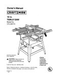
Sears
owners
manual
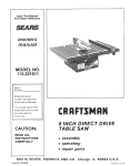
M O D E LN O .
ll3 .19771
SAWONLY
113.1977
5l
S A WW I T HL E G S
SeriaI
Number
M o d e la n d s e r i a l
n u m b e rm a y b e f o u n d
at the front of the base.
Y o u s h o u l dr e c o r db o t h
m o d e la n d s e r i a n
l umber
place
in a safe
for
f u t u r eu s e .
CAUTION:
ReadGENERAL
and ADDITIONAL
SAFETY
INSTRUCTIONS
carefully
IO-INCH
RADIAL SAW
o assemblV
o operating
o repair parts
S o l d b y S E A R S , R O E B U C KA N D C O . , C h i c a g o ,l L . 6 0 6 8 4 U . S . A .
PartNo. 63784
P n n r e c li n U . S . A
tools
f
o
r
P
o
w
e
r
i
n
s
t
r
u
c
t
i
o
n
s
s
o
f
e
t
Y
g e ne r o l
duringextendedPeriodsof
protectors(Plugsor muffs)
operation.
1 . K N O WY O U RP O W E RT O O L
c a r e f u l l v '. L e a r n r t s
;i;;J the owner's manual
a s w e l l a s t h e s p e c i fc
a p p l i c a t i o na n O r i m l t a i i o n i
t
h
istool'
t
o
p
e
c
u
l
i
a
r
o o t e n t i ahl a z a r d s
1 3 .S E C U R EW O R K
lt's
work when-practical'
Use clampso' a uii" to hold
operare
to
hands
both
frees
saferthan usingyour hand'
tool.
2 . G R O U N DA L L T O O L S
an approved 3-conductor
This tool is equipped with
type plug to fit the
cord and ' s-p'ong gtunding
Th: st-t:i conductor
tyit'""tpttti9
proper grounding
Never connect the
wire'
in the cord i, tnt ilou"Ollg
t
e
r
m
i
n
a
l
'
l
i
v
e
g r e e nw i r e t o a
3 . K E E PG U A R D SI N P L A C E
inworkingorder'andinproperadiustmentano
a l i g nm e n t '
A D JU S T INKGE Y S
4" R EM O V E
A N Dw R E N cH E S
F o r m h a b i t o f c h e c k i n g t o s e e t h a t k e yturning
s a n d a ttd ion'
usting
tool before
wrenches ar" r"*o-utd"from
N ,.^:
5 . K E E PW O R KA R E AC L E Ainvite
Floor
Cluttered ttt" unO Oenches sawclusr'
.accidents'
wax or
t"r.i "., be slipperydue to
ENT
SNVIRONM
6 . A V O I DD A N G E R O U E
or wet locations or
in damp
Don't use po*"' tools
wor'k area well lighted'
rc"tp
oin'
to
them
expose
work space'
surrounding
Provide adequate
7 . K E E PC H I L D R E NA W A Y
1' -4' .D O N ' TO V E R R E A C H
I*o
Keep tools
for lubricatingand
oerformance.f orroui instructions
changingaccessories'
TOOLs
16.DIscoNNECT
as
changing accessoriessuch
before servicing; when
blades,bits, cutters' etc'
AS
L TARTING
1 7 .A V O I DA C C I D E N"T
OFF" position before
Make sure switcn 's in
In.
with padlocts' master switches'
s t a r t e rk e y s '
9 . D O N ' TF O R C ET O O L
It will do the iob-Ot"*l"O
it wasdesigned'
1 0 .U S ER I G H TT O O L
Don't force too' i'-*"hment
d e s i g n e df o r '
plugging
SSORIES
1 8 .U S ER E C O M M E N D EADC C Efor
recommended
manual.
Consult the *tt;t
instructionsthat accompanY
the
rottow
tJitt.ii.t.
may
improperaccessories
the accessortt''ir''t use of
causehazards'
1 9 .N E V E RS T A N DO N T O O L tool
is tipped or if the
if the
Serious intu'v toJO ottur
contacted'
"u,ring tool is accidentally
or near the tool such that
Do not store materialsabove
tool to reachthem'
the
on
it is necessaryto stand
dt co.
-
at alltimes'
balance
ARE
1 5 .M A I N T A I NT O O L SW I T HCfor
best and safest
clean
sna'f ano
A||visitorssnoutdbekeptasafedistancefromworx
PI D ' P R O O F by
8 . M A K EW O R K S H OK
or
o t o p e rf o o t i n ga n d
removtng
20.CHECKDAMAGEDPARTS
guard or other part that
tnt tool' a
Before f urther "tJ
that it
"tt"iu"u ciected to ensure
[t
is damaged 'nouti
t.'""]l:l:
i1te1!eo
i1s
p"'iottn
will operate p,opi'iv tnd
movtng
m o v i n g p a r t s 'b i n d i n g o f
o
f
a
t
i
g
n
r
;
e
n
i
f
o
r
Check
otner
any
and
mounting'.
parts, breaKage o{ parts'
or
guard
A
its operation'
conditions tnt' 'it':tttect
r
e
p
a
i
r
ed
p
r
o
p
e
r
l
y
b
e
should
other part tnut it Outtged
or rePlaced'
which
s a f e ra t t h e r a t e f o r
to do a iob it was not
APPAREL
1 1 .W E A RP R O P E R
D o n o t w e a r I o o s e c | o t h i n g , g | o v e s , nin
e c kmoving
t i e s o r j parts'
ewe|ry
to ieicaugnt
(rings, wrist *tttnttl
protectrve
it rgcolnmeld-99 o*ttt
Nonslip toot*tti
long hair' Roll long sleeves
hair covering tJ "ontain
above the elbow'
2 l . D I R E C T I O NO F F E E D
the direction
or cutter^aga.rnst
Feedwork into a blade
onry'
cutter
oiiotation o{ the bladeor
2 2 . N E V E RL E A V ET O O L
UNATTENDED
(Head Protection)
12. USE SAFETY GOGGLES
with ANSI 287'1)
(must
comply
Wear Safety goggles
only have-'impact
ey-eglasses
lGtvOav
at all times.
glasses'Also" use
safety
triOi
resistantr.nstt, inty aie
is dusty' and ear
operation
cutting
ii
mask
face or dust
RUNNING
to a
leavetool until it comes
Turn power oti Oon't
comPletestoP'
2
addltional safety instructions for radial saws
CAUTION: Always disconnect the power cord before
removingthe guard,changingthe cutting tool, changingthe
set-up or making adjustments. Shut off motor before
performing layout work on the saw table.
W A R N I N G : D O N O T C O N N E C TP O W E RC O R D U N T T L
THE FOLLOWING STEPS HAVE BEEN
SATISFACTORILY COMPLETED:
l. Assemblyand alignment.
l l . E x a m i n a t i o na n d o p e r a t i n gf a m i l i a r i t y w i t h O N - O F F
switch, elevationcontrol, yoke index and lock bevel
index and lock, carriage lock, guard clamp screw,
spreaderand antikickbackdevice,and miter index and
lock.
I ll. Reviewand understanding
of all Safety Instructionsand
OperatingProcedures
thru-out manual.
INSTALLATION
1. Set carriagelock beforemovingthe saw.
2- Bolt the saw to the floor if it tends to slip, walk, or
s l i d ed u r i n gn o r m a lo p e r a t i o n .
3. Mount the saw so the table is approximately39,, above
the floor.
4. Mount the saw so the arm slopesslightly downwardto
the rear so the carriagewill not roll forward due to
gravity.
5. lf you attach any kind of table extensionsover 24,,
wide to eitherend of the saw,makesureyou either bolt
the saw to the benchor floor as appropriate,or support
the outer end of the extensionfrom the benchor floor,
as appropriate.
M IN IM ! Z EA C C I D E N TP O T E N T I A L
M o s t a c c i d e n t sa r e c a u s e db y F A I L U R E T O F O L L O W
s e t u pa n d o p e r a t i n gi n s t r u c t i o n s :
(A)GENERAL
- A v o i d a w k w a r dh a n d p o s i t i o n sw, h e r ea s u d d e ns l i p
could causea hand to moveinto a sawbladeor other
cutting tool. Never reach in back of or around the
cutting tool with either hand to hold down the
workpiece,or for any other reason;DO NOT place
fingersor handsin the path of the sawblade.
- Neversaw, dado, mold. or rabbet unlessthe proper
g u a r di s i n s t a l l e d
a n d s e t u p a si n s t r u c t e d _ NOTE TH E FOLLOWINGDANGER LABELS
W H I C HA P P E A RO N T H E F R O N T O F T H E Y O K E
ANDGUARD:
OANGER
DAIUGEF:
FoP Youn owil
SAF€TY
READ AI{O UI{O€RSIAND OWIIER'S MAI{UAL AEFONE OPERATING MACHIr{E.
r.waisaFCfrc6clEs.
a.usE"pusHsncr-roFuihowwonx,
gF sltluoE.
2. tEEpxdDs our oF patB
s. N€vai iuca ^rouio rxE s^wtLioE_
3. XiOWXOf TOIVOIO.i|CXAACXS,"
6. AIIOWIOOLrO SrOpOEFonE
AbJUSTTNG_
wABtllIluG: llail,oJi
T*?"'af#9335:iioi.l?
l1'j"u.l'^?,.31
ro ^vorD I
liJuiY
oo
NO' FECD ]
] uet:nrt
riro
I
, currttc
I T O O !r n o r
rHts
;
i
I
I
Eio
]
I
i
I
- l f a n y p a r t o f t h i s r a d i a ls a w i s m i s s i n go r s h o u l d
break, bend or fail in any way, or any electrical
componentfail to perform properly.shut off power
switch, removecord from power supply and replace
damaged,missingandlor failedpartsbeforeresuming
operation.
_ I F Y O U R S A W M A K E SA N U N F A M I L I A RN O I S E
O R I F I T V I B R A T E S E X C E S S I V E L YC E A S E
O P E R A T I N GI M M E D I A T E L Y U N T I L T H E
S O U R C E H A S B E E N L O C A T E DA N D T H E
PROBLEM
CORRECTED.
-WARNING: DO NOT ALLOW FAMILIARITY
(GAINED FROM FREOUENT USE OF YOUR
SAW) TO BECOME COMMONPLACE.ALWAYS
R E M E M B E RT H A T A C A R E L E S SF R A C T I O N O F
A S E C O N DI S S U F F I C I E N T O I N F L I C TS E V E R E
INJURY.
- Before starting work, verify that no play exists
betweenthe column & column support, or in the
carriage,and that arm. yoke, and bevellocks,/clamps
aretight.
- A largeproportion of saw accidentsis causedby use
of the wrong type blade,dull, badly set, improperly
sharpenedcutting tools, by gum or resinadheringto
c u t t i n g t o o l s , a n d b y s a w b l a d em i s a l i g n m e n
out-of-parallelwith the fence. Such conditionscan
causethe material to stick, jam (stall the saw) or
"KICKBACK"
a t t h e o p e r a t o r .N E V E R A T T E M P T
TO FREE A STALLED SAW BLADE WITHOUT
FIRST TURNING THE SAW "OFF". If thE
sawbladeis stalled or jammed, shut saw ,,OFF,,,
removeworkpiece,and checksawbladesquareness
to
table surfaceand to the fence,and check for heel.
Adjust as indicated.
- CAUTION: DO NOT cycle the motor switch ,,ON"
and "OFF" rapidly, as this might causethe sawblade
to loosen.In the event this shoutdever occur,allow
the saw blade to come to a complete stop and
re-tightenthe arbor nut normally, not excessively.
- D_o
1ot leavea long board unsupportedso the spring
of the board causesit to shift on the table. provide
proper support for the workpiece,basedon its size
and the tyBe of operationto be performed.Hold the
work firmly againstthe fence.
- Neverusea lengthstop on the
free end or edgeof the
workpiece whether crosscuttingor ripping. Never
hang onto or touch the free enJ of woikpiecewhen
crosscutting,or a free piece that is cui off while
power is "ON" and/or the saw bladeis rotating.In
s h o rt, the cut-off piece in anv ,,thru_sawinq"
operation must never be confined - it must 6e
a l l o w e dt o m o v el a t e r a l l y .
- Makesureyour fingersdo not
contactthe terminals
wheninstalling
or removing
t h e p l u gt o o r f r o m a l i v e
powersource.
- N e v e rc l i m b o n t h e s a w ,o r c l i m b
n e a rt h e s a ww h e n
power is "ON". Never leavethe saw with power
"ON",
or before the cutting tool has come to a
completestop. Lock the motor switchand pur away
the key when leavingthe saw.
- Do not use any blade or other cutting
tool marked
for an operatingspeedlower than 345b RpM. Never
usea cuttingtool largerin diameterthanthe diameter
for which the saw was designed.For greatestsafety
a n d e f fi c i e n c y w h e n r i p p i n g , u s e t h e m a x i m u m
diameterblade for which the saw is designed,since
under these conditions the spreaderis nearestthe
blade.
- Neverturn your saw "ON" beforeclearingthe table
or work surfaceof all objects(tools,scrapsof wood,
etc.) except the workpiece and related feed or
supportdevicesfor the operationplanned.
- D O N O T p e r f o r ml a y o u t .a s s e m b l yo.r s e t u pw o r k o n
t h e t a b l ew h i l e t h e c u t t i n gt o o l i s r o t a t i n g .
- N e v e r p e r f o r m a n y o p e r a t i o n" F R E E H A N D , ' .T h i s
term meansfeedingthe sawbladeinto the workpiece
or feedingthe workpieceinto the sawbladeor other
cutting tool without usingthe fence or someother
device which preventsrotation or twistinq of the
w o r k p i e c ed u r i n g t h e o p e r a t i o nN
. e v e r, , R t i , , i n t h e
crosscutposition. Nevermake a miter cut with the
arm in the 90o crosscutposition.
* N e v e rl o w e ra r e v o l v i n gc u t t i n gt o o l i n t o t h e
t a b l eo r
a workpiecewithout first locking the CarriageLock
K n o b . R e l e a steh e k n o b o n l y a f t e rg r a s p i ntgh e y o k e
Handle. Otherwise the cutting tool may grab the
workpieceand be propelledtoward you.
- The sawblade,dado, or other cutting tool must be
additional safety instructionsfor radial saws
removed from the saw arbor before using the
a c c e s s o r ys h a f t ( r e a r e n d o f t h e s a w m o t o r ) . N E V E R
o p e r a t et h e s a w w i t h c u t t i n g t o o l s ( i n c l u d i n gs a n d i n g
a c c e s s o r i e si n
) s t a l l e do n b o t h e n d s o f t h e s a w a r b o r .
(B) RIPPING
'l
. Never apply the feed force to the section of the
workpiece that will become the cut-off (free) piece.
Feed force when ripping must always be applied
between the saw blade and the fence . . . use a
"PUSH
STICK" (see pg. 261 for narrow or short
worK.
2. W h e n e v e r p o s s i b l e , u s e t h e i n - r i p p o s i t i o n - t h i s
p r o v i d e sm i n i m u m o b s t r u c t i o n f o r f e e d i n g b y h a n d
o r p u s hs t i c k a s a p p r o p r i a t e .
?
D o n o t r e l e a s et h e w o r k p i e c e b e f o r e o p e r a t i o n i s
complete - push the workpiece all the way past the
rear (outfeed or exit) of the sawblade.
4 . Make sure by trial before starting the cut that the
antikickbackpawls will stop a kickback once it has
s t a r t e d .K e e p p o i n t s o f p a w l s S H A R P I
Use a push stick when ripping short (under 12
i n c h e s )o r n a r r o w ( u n d e r 6 i n c h e sw i d e ) w o r k p i e c e s .
6. C A U T I O N : N e v e r r e p o s i t i o n t h e G u a r d o r
antikickback with power "ON".
"KICKBACK"
A
o c c u r sd u r i n g a r i p - t y p e o p e r a t i o n
when a part or all of the workpiece is thrown back
violently toward the operator. lt can occur when
t h e w o r k p i e c ec l o s e si n o n t h e r e a r ( o u t f e e d s i d e ) o f
the sawblade (pinching), binds between the fence
and the sawblade (heel), or is grabbed by the
sawblade teeth (wrong-way feed) at the outfeed
"PlNCHlNG"
side.
is generallyavoided by
u t i l i z a t i o n o f t h e s p r e a d e r ,a n d a s h a r p s a w b l a d eo f
the correct type for the workpiece being cut.
' 'H
E EL " c a n b e a v o i d e d b y m a i n t a i n i n g t h e
s a w b l a d ee x a c t l y p a r a l l e l t o t h e f e n c e . G r a b b i n gb y
the sawblade teeth can be caused by heel or by
f e e d i n gf r o m t h e w r o n g d i r e c t i o n ( s e e " D A N G E R "
wa rning on guard)
it can be avoided by
maintaining parallelism of sawblade to fence,
feeding into the sawblade from the nose of the
g u a r d o n l y , a n d b y p o s i t i o n i n g t h e s p r e a d e ra n d
antikickback property, and keeping the workpiece
down on the table and against the fence.
8. Position the nose of the guard to just clear the
w o r k p i e c e , a n d p o s i t i o n / a dj u s t t h e a n t i k i c k b a c k
and spreaderdevicesas instructed.
9. NEVER cut more than one piece at a time by
s t a c k i n gw o r k p i e c e sv e r t i c a l y .
10. NEVER feed a workpiecethru the saw with another
p i e c e ( b u t t i n g s e c o n d p i e c e a g a i n s tt r a i l i n g e d g e o f
p i e c e b e i n g c u t ) , e v e n i f o f t h e s a m e t h i c k n e s s .F e e d
e a c h w o r k p i e c e i n d i v i d u a l l y t h r u t h e s a w b l a d e ,a n d
c o m p l e t e l y b e y o n g t h e s a w b l a d e ,b e f o r e r i p p i n g t h e
next workpiece. Use push stick if the rip cut is less
than 6" wide.
1 1. D O N O T p u l l t h e w o r k p i e c e t h r u t h e s a w b l a d e
- p o s i t i o n y o u r b o d 1 , a t t h e n o s e ( i n - f e e d )s i d e o f
the guard: start and complete the cut from that
same side. This will require added table support
for long pieces.
1 2 . P l a s t i ca n d c o m p o s i t i o n ( l i k e h a r d b o a r d ) m a t e r i a l s
m a y b e c u t o n y o u r s a w . H o w e v e r , s i n c e t h e s ea r e
usually quite hard and slippery. the antikickback
p a w l sm a y n o t s t o p a k i c k b a c k .
T h e r e f o r e ,r i p w i t h t h e f i n i s h e d s i d e d o w n ( n e x t t o
t h e t a b l e ) a n d b e e s p e c i a l l ya t t e n t i v e t o f o l l o w i n g
proper set-up and cutting procedures.Do not stand,
or permit anyone else to stand, in line with a
potential kickback.
1 3 . W h e n s a w i n g 1 / 4 " o r t h i n n e r m a t e r i a l s ,f o l l o w a l l
normal ripping procedures except set sawblade into
table top at least 1/8". DO NOT let go of or stop
feeding the workpiece between the blade and fence
until you have pushed it completely past the
antikickback pawls. Otherwise the workpiece could
get into the back of the sawblade and be thrown
v i o l e n t l y f r o m t h e s a w i n t h e d i r e c t i o n o p p o s i t et o
the feed direction. This is the same action that
would occur if the instructions of the DANGER
warning on the guard is aborted. Do not stand,or
permit anyone elseto stand, in line with the path of
a workpiece that may be thrown from the saw in
this manner.
1 4 . P o s i t i o n t h e s a w s o n e i t h e r y o u , a h e l p e r ,o r a c a s u a l
observer is forced to stand in line with the
sawblade.
15. Use extra care when ripping wood that has a twisted
grain or is twisted or bowed - it may rock on the
table and/or pinch the sawblade.
(C)CROSSCUTTING
1. ALWAYS RETURN THE CABRIAGE TO THE
F U L L R E A R W A R D P O S I T I O NA T C O N C L U S I O N
O F E A C H C R O S S C U TT Y P E O P E R A T I O N . N e v e r
r e m o v e y o u r h a n d f r o m t h e Y o k e H a n d l eu n l e s st h e
c a r r i a g e i s i n t h i s p o s i t i o n . O t h e r w i s et h e c u t t i n g
tool may climb up on the workpiece and be
p r o p e l l e dt o w a r d y o u .
Place guard in horizontal position and adjust
a n t i k i c k b a c k p a w l st o j u s t c l e a r t h e t o p o f t h e f e n c e
o r w o r k p i e c e ,w h i c h e v e ri s h i g h e r .
3 . N E V E R g a n g c r o s s c u t- l i n i n g u p m o r e t h a n o n e
workpiece in front of the fence - stacked vertically,
or horizontally outward on the table - and then
pulling saw thru: the blade could pick up one or
m o r e p i e c e sa n d c a u s ea b i n d i n g o r l o s s o f c o n t r o l
a n d p o s s i b l ei n j u r y . '
4. Do not position the Arm so the operation you are
perf orming permits the cutting tool to extend
beyond the edgesof the Table.
2.
(D) ACCESSORTES
1 . U s e o n l y r e c o m m e n d e da c c e s s o r i eass l i s t e d o n p a g e
34.
2.
N e v e r o p e r a t et h i s s a w w h e n e q u i p p e dw i t h a d a d o
head or molding head unless the molding head
guard is installed - see listing of recommended
a c c e s s o r i e sT. h e o n l y e x c e p t i o n i s w h e n " t o p - s i d e "
d a d o i n g o r m o l d i n g , w h e n t h e s a w b l a d eg u a r d m u s t
b e u s e d . S e e d e t a i l e d i n s t r u c t i o n st h a t a c c o m p a n y
the dado head, molding head, and molding head
guard.
T h e u s e o f a b r a s i v eo r c u t - o f f w h e e l s , o r w i r e
w h e e l s , c a n b e d a n g e r o u sa n d i s n o t r e c o m m e n d e d .
(Abrasive or cut-off wheels are used to saw many
different materials including metals, stone, and
g l a s s).
4. Drill Chuck: Do not install or use any twist drill
fa r g e r t h a n 1 | 2 - i n c h i n d i a . , o r i o n g e r t h a n 7 i n c n e s
i n l e n g t h o r e x t e n d i n g m o r e t h a n 6 i n c h e sb e y o n d
the chuck jaws. Do not install or use any reduced
s h a n k d r i l l e x c e p t o f t h e s p a d et y p e ( 1 i n c h d i a . o r
smaller). "Use for drilling WOOD and PLASTIC
onlv."
WEAR YOUR
The operation of any power tool can result in foreign
objects being thrown into the eyes, which can resultin
se.vgre9y9 damage.Always wear safety gogglescomplying
with ANSI 287.1 (shownon packagetOJtorecommencing
power tool operation.Safety Gogglesare availableat Seari
retailor catalogstores.
electrical connections
POWERSUPPLY
1. Motorspecifications
The A-C motor used in this saw is a capacitor-start.
non-reversible
type havingthe following specifications:
Voftage
eO/24O
Amperes
11l1.s
H e r t z ( c y c l e. .s. ).
.......60
Phase
. . Sinqle
RPM .
... 3460
Rotationasviewedfrom sawbladeend . . . . Clockwise
CAUTION: Your saw is wired for 12Ov operation.
Connectto a 120V, l$Amp. branch circuit and use a
15-Amp. time-delay fuse or circuit breaker. lf the
motor is used tor 24OY operation, connect to a
15-Amp. branch circuit and usea 1S-Amp.time-delay
fuse or circuit breaker.
This machinemust be groundedwhile in useto protect
the operatorfrom electricshock.
I F Y O U A R E N O T S U R ET H A T Y O U R O U T L E T I S
P R O P E R L YG R O U N D E DH, A V E I T C H E C K E DB Y A
O U A L IF IE D E L E C T R I C I A N .
W A R N I N G : D O N O T P E R M T TF T N G E R ST O T O U C H
T H E T E R M I N A L S O F P L U G SW H E N I N S T A L L I N G
OR REMOVING THE PLUG TO OR FROM THE
OUTLET.
W A R N I N G : I F N O T P R O P E R L YG R O U N D E DT H I S
POWER TOOL CAN INCUR THE POTENTIAL
HAZARD OF ELECTRICAL SHOCK.
PARTICULAR LY WHEN USED IN DAMP
LOCATIONSIN PROXIMITY TO PLUMBING. IF AN
ELECTRICAL SHOCK OCCURS THERE IS THE
POTENTIAL OF A SECONDARYHAZARD SUCH AS
YOUR HANDS CONTACTINGTHE SAWBLADE.
I F P O W E RC O R D I S W O R NO R C U T , O R D A M A G E D
IN ANY WAY, HAVE IT REPLACED
IMMEDIATELY.
lf your unit is for use on lessthan 150 volts it has a
plugthat lookslike below.
3 - P R O N GP L U G
PROPERLY
GROUNDED
OUILET
t
ff-r]t
o t
o
fil
\ "
GROUNDING PRONG
'
This power tool is equippedwith a 3-conductorcord
and groundingtype plug which has a grounding
- prong,
Listed by Underwriters' Laboratories.The ground
conductorhasa greenjacketand is attachedto the tool
housingat one end and to the ground prong in the
attachmentplug at the other end.
This plug requiresa mating 3-conductorgroundedtype
outlet asshown.
lf the outlet you are planningto usefor this powertool
is of the two prong type DO NOT REMOVE OR
ALTER THE GROUNDING PRONGIN ANY
MANNER. Usean adapterasshownand alwaysconnecr
t h e g r o u n d i n gl u gt o k n o w n g r o u n d .
It it recommendedthat you havea qualifiedelectrician
rypF9e the TWO prongoutlet with a properlygrounded
T H R E E p r o n go u t l e t .
An adapteras shown below is availablefor connectinq
plugsto 2-prong receptacles.
The greengroundinglu!
extending from the adapter must be connectedto i
permanent ground such as to a properly grounded
outlet box.
G R O U N D I N GL U G
ADAPTERI
M A K E S U R ET H I St S
CONNECTED
TO A
KNOWN GROUND
3-PRONG
PLUG
-i--'--
2-PR.NG
RECE
PTACLE
NOTE: The adapter illustratedis for use only if you
alreadyhavea properlygrounded2-prongreceptacle.
ELECTRICALCONNECTIONS
WARNING: CHANGES tN ELECTRTCAL
C O N N E C T I O N SS H O U L D B E M A D E B Y A
O U A L IF I E D E L E C T R I C I A N .
I . ChangingMotor Connections
a. Under normal home workshopusage,and if proper
(full) vell3gqis suppliedto the motor, your sawwill
operate efficiently on 120V, as connectedat the
factory. However,if any of the followingconditions
exists,it will be advisablefor you to reconnectthe
. motor for 24OY operation - to obtain the
efficiencyand performancefor which your saw is
designed:
(1) Heavy-dutyoperations.
(2) Either an undersizedor an overloadedbranch
circuit servingthe saw motor.
(3) Low voltage supplied by the power source,
which the power companycannotcorrect.
b. Motor wiring connectionsfor 120V (asmadeat the
factory) are described below. Necessary
reconnections
for 240V operationarealsodescribed
following. Wheneverchanging connectionsfrorh
120V to 24OY or vice-versa,
make certain thatall
necessarysteps (including proper fusing of the
branchcircuit) are completed.
electricalconnections
to a 240V
is co-nnected
d. Make certain the receptacle 2a0v
circuit
a
!1nctr
A-c power t'ppl;;;;Gh
bv
a1d-1;'otected
itpacitv'
havingat leastt,i'S-ttp'
breaker'
circuit
a 1S-amp'trme-oelayfuseor
MOTORSAFETYPROTECTION
5unc:
"vacuumed"'
blown out' or
NOTE: This motor should be
interferencewith normal
freouently to prevent ;;ilil
motor ventilation.
al-reset'
Y o u r s a w m o t o r i s e q u i p p e d, ytti t l ^ i . m a n upower-l
i ne
99:l a
lltsafevalue'
thermal-overload protecto-rTtlilntO exceeds
circuit when the rnorora'.'.p.raiure
r 20v I 240v
I O R U s EO N
rero oru
EROWN LEAD ON
o
1
5
l
8
for 120V A'C'
2. Connections
from motor to expose
a.- Ratou" nameplatecover
terminalboarcl'
as
motor must be connected
u. ii. *ir., insideof the
shown:
n u m b e r6 t e r m i n a l '
( 1 ) T h e o r a n g e - c o l o r ewdi r e o n
n u m b e r5 t e r m i n a l '
(2)The b'o*n-coto"d wire on
PROTECTOR
( R E DB U T T O N )
c.Usethel20Vpower.cordp|ugfurnishedwithyour
saw'
motor'
the line and'stopsthe saw"OFF"
'ittt'-iaw
1. lf the protectoropens
the
to
switch
immediately p""
cool'
p"titf "", and allowthe motor to
F O RU S EO N
O R A N G EL E A DO N
gRowl rtlo ON
I 20V 240V
6
8
5
7
3. Connectionsfor 240V A'C'
terminal box must be
a. The wires insidethe motor
connectedasfollows:
wdi r e o n n u m b e r8 t e r m i n a l '
(1) The orange-colore
7 terminal'
w
( 2 ) T h e b r o w n - c o l o r e di r e o n n u m b e r
a (3-blade)
with
plug
power-cord
b. Replacethe 120V
po*ti-"ord..white and
"hot" plug
240V plug, "onn"Jting'tnt
the two
to
black leads, "'ptiiiuJrv'
po*tt-cord grounding
blades- ,no "onnJttlnj irtt
wire to the PluggroundProng'
G R O U N D I N G B L A D E1 5
L O N G E S TO F 3 B L A D E S
24OVPLUG& RECEPTACLE
2 . A f t e r c o o l i n g t o a s a f e o p e r a manually
t i n g t e mby
p epushing
rature,the
overloadprotector "tn U" "iot"A
red
lf
the
of the motor.
in the red button Jn ar,. ,op
motor
the
placeimmediately'
button will not tntf into
cool for a while
is still too hot and Lutt U" allowed-t^o minutes.(An
take20-30
lonqer.In some".r., aii, ,ry
protector is closed')
r"ril[:'I, "ii"[ *irr l"oicate
-Uewill snap into running
3. As soon as the red button start-ed^'andoperated
tty
tt*"ON"
the
position.
saw switch to the
normally, by pulling o"'tft"
position'
circuit lrealers may result
4. Frequentopeningof fusesor
the motor circuit is fused
if
or
-""ot-endations'
if motor is overlo]deJ'
Overloadingcan
differently tr.ot
is misaligned
sa;v
if
or
Your
occur if you feed;itpiJtv
use
not
Do
heels'
blade
.u
1-t-t-,:,f^:t"tttt
so that the
qualifiedelectrlclan'
"apicitv without consultinga
for operationon the
5. Although the motor is designed t::ot nameplate'
voltage anO t'equl-ncv tpu"iiitO 9n, on voltagesnot
sa.fely
normal toads wiri Ue handled
the nameplatevoltage'
below
or
atove
tO'U"
more than
at motor
require
.lltl ,u-oltust
Heavy loads, no*u"tt'
nameplate'
on
terminals.q"r' trtl-*itage'specified
6 . M o s t m o t o r t r o u b | e s m a y b e . t r areduced
cedtolo
oseor
input
incorrect tonntii'ont' overloading'
or
circuit)
supplv
thJ
in
voltage(suchastt"ritiit *ites
check the
to an overly-'""n'-t"ooit'-liicuit' ,Always
supply.circuit' whenever
connections,tnt ioJ tnd the
Checkwire
il""p#ott.ttliiltclorilv'
the motor tairt
followrng'
iit". .nO lengthswith the table
N O A D A P T E RI S
A V A I L A B L EF O R
THIS TYPEPLUG
c.
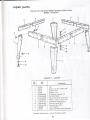
W I R ES I Z E S
loss of
cord-will causesome
The use of any extension minimum and to prevent
i
power. To t""p ii"it-'io
3-blade receptacle'
Plug your saw into a24OY '
6
I
over-heatingand motor burn-out, use the table below to
determinethe minimum wire size(A.W.G.)extensioncord.
Use only 3 wire extension cords which have 3 prong
grounding type plugs and 3-pole receptacleswhich accept
the tools plug.
Wire Size Required
.
lAmerican Wire Gauge Numberl
240 Volt Line | 120 Volt Lines
Up to 100 feet
100 feet to 200 feet
200 feet to 400 feet
NOTE: For circuits of greaterlength,the wire sizemust be
increasedproportionatelyin order to deliveramplevoltage
to the saw motor.
LOCATIONSAND FUNCTIONSOF CONTROLS
MITERSCALE
AND INDIC,ATOR
ARM CON-TROLLEVER
BEVELINDEX LEVER
RIP SCALEINDtCATOi
SWIVEL
LATCHLEVER
ON-OFF SWITCH
W I T HK E Y
ARM LOCK
ADJUSTINGWHEEL
TABLECLAMP
RIP SCALE
INDICATOR
CARRIAGE
LOCK KNOB
YOKE LOCK
HANDLE
ANTIKICKBACK,SPREADER
ADJU5TINGW]NG SCREW
ANTIKICKEACK
AND SPREADER
ASSEMBLY
EEVELINDEX
INDICATOR
ACCESSORY
SHAFT
CONTENTS
Guarantee
......2
G e n e r aSl a f e t yI n s t r u c t i o nf os r P o w e rT o o l s . . . . . . . . .
2
A d d i t i o n aSl a f e t yI n s t r u c t i o nf os r R a d i aSl a w s . . . . . . .
3
ElectricalConnections
........5
AssemblyandAlignm
. . e. .n t
........8
UnpackingandPreassembly...
.:.... g
AlignmentProcedure
.......12
Locationand Functionsof Controls
BasicSawOperations
Adjustmentsto Conipensate
for Wear
Trouble-Shooting
Maintenance
and Lubrication . .
RecommendedAccessories
RepairParts
20
23
28
31
34
34
?tr
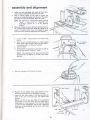
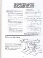
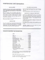
assembly a n d a l i g n m e n t
@::=€
@F-=-S
7/ 16-inch wrench
'l
/Z-inch wrench
9/1 6-inch vvrench
>
TooLs NEEDED
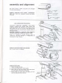
FRAMTNG
souAREMUsrBETRUE
C H € C K I N GA C C U R A CO
YF
I N S I D EO F S Q U A R E
s \ _ , ! l ! j : l , -
R E A RE D G EO F F R O N TT A B L E
(FENCE,SPACER
AND BACK
BOARDS
REMOVED)
\d-=$l-]
S c r e w d r i v e r( m e d i u m )
S c r e w d r i v e r( s m a l l )
C H E C K I N GA C C U R A CO
YF
OUTSIDE
OF SQUARE
DRAW L I G H T L I N E O N
TABLEA L O N G T H I S E D G E
D R A WL I G H TL I N E O N
T A B L €A L O N G T H I SE D G E
Framing
square
Pliers
S H O U L D8 E N O G A P O R
O V E R L AH
P E R €W H E N
SQUARE
I S F L I P P EO
DV E R
IN DOTTED
POSITION
:.Pencil
U N P A C K I N GA N D P R E A S S E M B L Y
W A R N I N G : D O N O T C O N N E C TT H E P O W E RC O R D T O
A S O U R C EO F P O W E R .T H I S C O R D M U S T R E M A I N
U N P L U G G E DW H E N E V E RY O U A R E W O R K I N G O N
THE SAW.
M o d e l 1 1 3 . 1 9 7 7 1R a d i a lS a w i s s h i p p e dc o m p l e t ei n o n e
c a r t o nb u t D O E SN O T I N C L U D ES t e e lL e g s .
Model 1 13.197751RadialSaw is shippedcompletein one
cartonbut INCLUDESSteelLegs.
1. Unpackingand CheckingContents
Separateall "loose" partsfrom packaging
materialsand
check each item with "Table of LooseParts" to make
sure all itemsare accountedfor, beforediscardingany
p a c k i n gm a t e r i a l .
lf any parts are missing,do not attempt to assemble
radial saw, plug in the power cord, or turn the switch
o n u n t i l t h e m i s s i n gp a r t sa r eo b t a i n e da n da r e i n s t a l l e d
correctlv.
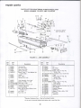
(?,
LI
Key No.
I
I
?
4
E
o
7
SHOULDBE NO GAP OR
OVERLAPHEREWHEN
SAUAREIS FLIPPED
OVER
IN DOTTEO
POSITION
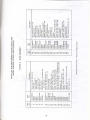
Table of Loose Parts
Basic
Sawassembly
Reartable
Tablespacer
R i pf e n c e
F r o ntta b l e
Channel,
TableMtg.
"Owner's
Manual"
LoosePartsBagPartNo.63794
( c o n t a i n itnhgef o l l o w i nigt e m s ) :
Rip-Scale
Indicator
TwinNut(forattaching
rip-scale
indicator)
Machine
PanHd.,6-32x7116"
Screw,
Hex" 1" Wrench,
I /4
H e x" 1 " W r e n c 3
h /, 16
ElevatiC
o nr a n k A s s e m .b. l. y.
ArborWrench
ShaftWrench
* LoosePartsBagPartNo.63795
{ c o n t a i n itnhgef o l l o w i nigt e m s ) :
Machine
PanHd.,'ll4-20x 1"
Screw,
Washer,
Steel(Flat),17164x 518x 1132" . .
"T"
Nut,
PanHd.114-20
Screw,
x 1-314"
Nut,Hex114-20.
L o c k w a s h e r . .1. 1
.4
T a b l eC l a m p
*LoosePartsBagPartNo.63796
( c o n t a i n itnhgef o l l o w i nigt e m s ) :
H e x" 1 " W r e n c h1,1 8 ". .
SwitchKey
Lockwasher,5/16"
W a s h eFrl,a t1 1 / 3 2x 7 1 8 x 1 1 1 6 "
SetScrew,
CupPt.1/4-20x 1" - N u t ,L o c k5 / 1 6 - 1 8
B o l tS
, q .H d .5 / 1 6 - 1x8 3 1 4 " .
r Y a s h e r . 2 1xl E94i 1 6x 1 / 1 6 "
N u t ,H e x5 / 1 6 - 1 8
*Thisbagincluded
in Loose
PartsBagNo.63794
€lty.
L
z
4
5
I
I
A
2
1
1
+
1
2
2
I
The fof fowing parts are includedwith Model 113'197751.
Key
No.
'|
2
3
4
5
5
6
6
6
7
8
I
Table of Loose Parts
L e g. . .
L.H. ..
Stiffener,
R.H. . .
Stiffener,
LoosePartsBagPartno. o'si'S'Z'
(containing
items):
thefollowing
- Screw.Truis Hd. 114'20x5l8 - . .
- Lockwasher,
l/4 External
- Lockwasher.
5/16External
- Nut,Hex114'20.
- N u t ,H e x J a m5 / 1 6 { 8
- Nut,Hex112-13.
- Foot.Leveling
- Screw,
x 5/8 .
HexHd.5/16-18
- W a s h e1r 1
. 1 3x2 l 1 / 1 6x 1 / 1 6 . .
,$a
oty.
4
4
4
Ug e
s}{"
40
40
I
40
8
8
4
8
't6
5
a
6
\E{
r-))
FJ
g
v
""
""1:
o l o
o
.
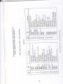
NOTE: Steel Legsare furnishedwith Model 113.197751
From amongthe looseparts,find the followingHardware:
TrussHeadScrews,114-20x5/8
1/4-External
Lockwashers,
Hex Nuts, 1/4-2O
Hex Nuts, 1/2-13
LevelingFeet
9
8
7
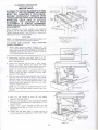
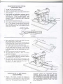
A S S E M B L I N GS T E E L L E G S
40
40
40
8
4
@
a\_-/J
</t'u
o l o
o
STIFFENER
R.H.
STIFFENER
L.H.
21-1/4"+
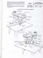
Assemblethe Legsas shown.
1. AssembleTwo (2) eachof right and left handStiffeners
to the length shown using 1/4-20 x 518" truss head
and hex nuts.
screws,lockwashers
o
o
o
o
2. Attach the four {4) legsto the Stiffenersusing1/4-20
and nuts.
screws,lockwashers
o
STIFFENER
t l J
3. Installlevelingfeet as shown.To levelsteellegs,loosen
nut on insideof leg and turn nut on outsideto raiseor
and then
lowerfeet.Adjust all four levelersif necessary,
tightennuts on insideof leg.
N O T E :T h e s e l e v e l e r s a r e n o t i n t e n d e df o r h e i g h t
adiustment.
CAUTION: Levelingfeet must be adjustedso the sawdoes
not rock AND so that the arm slopesslightlydownwardto
the rear so the carriagewill not roll forwarddue to gravity.
e.-5
&\,
9
lo
o
o
o
o
o
o
o
o
STIFFENER
o
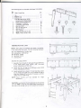
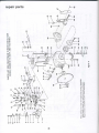
REMOVESKTDSFROM BASE
MOUNTINGSAW
1.
.FroT among the loose parts, find the following
hardware:
8
8^
16
8
Hex HeadScrews,5/16_1g
x 5/g
5/.l6 in. exierna'tlype
.Lockwashers,
W a s h e r s1,1 / 3 2 t D
H e xJ a m N u t s , 5 / l G l g
2. Placesaw on legsso that holesin bottom of saw line
up
with holesmarkedX in top of legs.
3. lnstall screws,washersand nuts asshown.
lf you mount the saw on any other Craftsman
baseor flat
bench, make sure Elevation Crank has propei clearance
to
rotate. The saw must be bolted down. position
saw to slope
sligh-tlyrearward,so when the carriageis instailedit wiil
not
roll forwarddue to gravity.
SAW BASE
HEX HEADSCREW
FLAT WASHER-
S T I F FN
EE R
FLAT WASHER
/
loc<wassen
HEXNUT
ATTACHELEVATIONCRANK.
Besuresetscrew
is tightenedon flat of shaft.
ELEVATE ARM TO ITS MAXIMUM HEIGHT.
Removeshippingblock and discard.
ro
R.H. STIFFENER
assemblyand alignment
BE positiveswitch is "OFF" and power cord unplugged
thru-outentireprocedure.
REMOVE CARRIAGE STOP SCREW, LOCKWASHER
AND TAG. Read and understand warning tag before
discarding.
@t*ofi:fo
LocKwAsHER
6p
&
, sToPscREw
V*n'*rrt
rillto*tt
L O C KA R M B E F O R EP R O C E E D I N G .
H O L D I N G C A R R I A G E A S S E M B L YW I T H B O T H
HANDS, CAREFULLY START AND SLIDE THE
C A R R I A G EO N T O T H E T R A C K S .T h e a s s e m b l ym u s t b e
held parallelwith the arm so that all four bearingsslide
smoothly onto the arm, preventingany excessive
strain on
bearings
and track.
W A R N I N G : R E I N S T A L L C A R R I A G E S T O P S C R E WT O
P R E V E N TC A R R I A G EF R O M R O L L I N GO F F A R M .
Check for
"Adjusting
loosenessof carriage bearings. Refer to
C a r r i a g e B e a r i n g s "i n " A d j u s t m e n t s t o
Compensate
for Wear"Section.
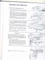
R E M O V ES H I P P I N GS C R E W SA N D D I S C A R D .
Use of pliers may be necessary.
REMOVESAW BLADE.
1. Tightencarriagelock knob.
2. Loosenguardclampscrew,removeguard.
3. Motor shaft has left hand threads.Hold shaft wrench
and rotate arbor wrench down (clockwise).
4, Removeshaft nut, outer collar, saw blade, and inner
collar.Set asideand out of the way.
VIEWOF UNDERSIDE
OF MOTOR
SHOWINGLOCATIONOF TWO
SHIPPINGSCREWS
PULLDOWN
TO LOOSEN
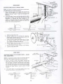
A L I G N M E N TP R O C E D U R E
IMPORTANT:
S Q U A R EH D . S C R E W
s/16-18 x 3/4
T A B L EM O U N T I N G
S U P P O RCTH A N N E L
IN ORDERTO OBTAINMAX'MUMCUTT'NG
ACCURACY,THE FOLLOWI'VGS'X STEPS
M U S T B E C A R E F U L L YF O L L O W E D .
BECOME THOROUGHLY FAMILIAR WITH
THESESTEPSSO THAT YOU CAN ALWAYS
MAINTAIN YOUR SAW 'N PROPER
ALIGNMENT.THE ACCIJRACYOF EACH
ADJUSTMENT 'S ALWAYS DEPENDENT
OF THEPRECEDING
UPONTHE ACCIJRACY
ADJUSTMENT.
After following the 6 step assembly and alignment
procedure and the Basic Saw operation section refer to
Trouble Shooting section if any difficulty is experienced
when performing any sawing operation.
FLAT WASHER
S T E PO N E
F R ON T
N O T E : T h e f o l l o w i n g a d j u s t m e n t ,p e r f o r m e d p r o p e r l y , w i l l
r e s u l t i n t h e w o r k t a b l e b e i n g p a r a l l e lt o t h e a r m .
M O U N TR A I L SU 5 I N G
INI)E
ATTACHING AND LEVELING TABLE MOUNTING
S U P P O R TC H A N N E L S .
1. A t t a c h t a b l e m o u n t i n g s u p p o r t c h a n n e l s w i t h f o u r
s o u a r e h e a d 5 / 1 6 - 1 8 x 3 / 4 s c r e w s ,l o c k w a s h e r sa n d f l a t
w a s h e r sa n d n u t s . P O S I T I O NS C R E W Sl N C E N T E R O F
C H A N N E L S L O T S , f i n g e r t i g h t t o p e r m i t c h a n n e l st o
"slip"
a g a i n s tt h e b a s ew h e n l e v e l i n g .
2.
hULE)
UNLOCK
LOCK
I N D E XR E L E A s T
POSlTtN
O
'i'\
R e l e a s eb e v e l l o c k l e v e r , m o v e b e v e l i n d e x p i n t o l e f t
and rotate the motor to position saw blade, end of shaft
down. Lock bevel lock.
Unlock and hold arm control lever in index release
position as shown. Position arm against left stop
( a p p r o x i m a t e l y 5 0 o m i t e r ) . L o o s e n c a r r i a g el o c k k n o b
a n d p o s i t i o n c a r r i a g ed i r e c t l y o v e r l e f t h a n d c h a n n e l '
N O T E : F o r s a f e t y r e a s o n si n a c c o r d a n c ew i t h t h e U L
standard, stops have been provided to prevent 3600
r o t a t i o n o f t h e r a d i a la r m .
4. S l i d e t h e a r b o r w r e n c h h a n d l e b e t w e e n e n d o f m o t o r
shaft and mounting channel to act as a feeler gauge.
Carefully lower the motor with elevationcrank until
the end of shaft is just touching the arbor wrench.The
wrench should slide back and forth with only slight
"A".
resistance.Tighten screw
N O T E : D o n o t c h a n g et h i s e l e v a t i o ns e t t i n g u n t i l b o t h
l e f t a n d r i g h t h a n d t a b l e s u p p o r t c h a n n e l sh a v e b e e n
ad i usted.
"8"
and tighten
Move arm and carriage to screw
m
a
n
n
e
r
.
s
a
m
e
support in the
M o v e a r m a n d c a r r i a g et o r i g h t h a n d s u p p o r t c h a n n e l
and level in the same manner you adjusted the left hand
support channel.
Recheck both support channels to make sure that
tightening screws did not affect the accuracy of the
adjustment.
8 . Elevate saw and place motor in vertical position to
p r o v i d e c l e a r a n c ef o r i n s t a l l a t i o no f f r o n t ( w o r k ) t a b l e .
5.
ARBORWRENCH
SCREW"8"
SCREW
t2
TABLEMOUNTING
S U P P O RCTH A N N E L
(LEFTHAND)
assembfyand alignment
F R O N TT A B L T
INSTALLATTONOF FRONT (WORK)
TABLE.
EOITOMS
O F I
1. Placefront table board
upsidedown
-ir,J'iJr.,
on a workbenchor
on the f loor. Drive f_"ui
into
that is not
counterbored.
2. Align the counterbored
.holeswith matchingholes in
support channels. Instail
the tir:" l)ifil'"tnch
flat
washers,and four % _.2g
" ii""i.,-p#-'H?o macnine
screvvs.
Just baretystart the
poin;;;;'r;"ie"w and the
one(1)%- 20x 1-3/4 gup
pii
inch
3.
i;J
il;riJ screw
,n
table center holesInstall one % lockwasher
and Hex Nut on each
of the
four (4) screws in the support
channelsand tighten.
4.
,fL:::
l-
:+cuP PO|NT
s E TS C R E W
ol edgeacrossthe front tabre
::.: ::_b],._.b:.,d
;;1'J:
["J,ffn' jJi"n?l".ogi^tj-t-iT4;il:':Jffi
ir,.r."t i.ir; il'o'i1,il;ii.:;
f_ffil::,whether
low at its center.
5. lf the front table is,trigh.
a t c e n t e r ,f i r s t t i g h t e n t h e
center (% _ 20 x 1-3/4
notOOownscrewuntil the
t a b l e i s t e v e l_ t h e n l i s ,inch)
h l e nt h ; i ; ; ; ' # w
untitthis
s c r e wi s s n u g .
lf table is low at center.first
tighten the levelingscrew
untir the tabte is tevet_
til i;e;;;"inJ
noro oo*n
screw.
taOtgis.not high or low,
tighten levelingscrewanol
itcenter
hold down screwsnuq.
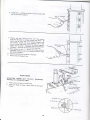
STEPTWO
ADJUSTINGCOLUMN TUBE
IN COLUMN SUPPORT
f o , o w i n g a d j u s t m e n its
|.9TE: ,The
very CRtTICAL.Atl
pro"-"durgl
l1Y: -1is",t.nt
l.rv on th is'adlustmentbeino
correctry.
ALL'Looa-irui"dj"
rvrUii";;
BtilB'rft;1
1. Index and lock arm
at 0o Miter.
While holding the arm rrvith
o n e h a n d , h o l d f i n g e r so f
other hand as shown, between
column iuOe ano column
Appty gentte side presi"r.-;;-the
:opposing
leeo1
arm in
directions.,
rotational
.Anv ,io. 1"-rid."",
movement (indicated by
arrow) ;
il;.;'*ith
finger.
lf looseness exists the following
adjusrments are
requ i red.
2. Remove Column Stupport
trim using screwdriver
shown.
as
LEVETING
S E TS C R E W
F R O N TT A B L E
3. L,oosen(2') % - 20 Gib set
screwson the left side
rearof the columnsupport.
at the
4. Elevate,and then
_ . , . " ^ r , , , . (a)
r r rthe
r d , if
n e ccolumn
olumn
bincts
b
i n d s :nrr
a n d -,-.,-.,^-t?y:,l,lh".Arm:
e l e v a t i o nl ;
loosen
two 5/16 _ id
Dtarprr nr,+. ^^ 3_-_^ .diffic-ult
j:,;"1;
jl.it,iil.-ii;;";;ilT#
3:i1,1^ly::^"1
but
firm-.r.r.,i"".'i6)
tf ths
I:,i,j:T"::^.rT::,1 -- *iir,
i"
ff
uurumnsupport,
H;,i::ilo",l;
n,r1g,nf:^,:o;
tighten
:.,iJ"
the two s/16 - lg.plated
5.
nuts until movement
disanne:,.
ar^.,^r:^_
-,
d
isappea
rs-_ e
Ievat
ionrr,.i
rI' [. ili ;:?,#.i ;i#:
Now tinhto- rlr- /rr 1/ _ ^^ ^..
2g Gib;;;;;;;s untirno
**":r*::,:f,.^-(^2,)!:
;;#'ff Hirffi
::i'""':,?*:""t:l:l3lpr'v""i'ts-f
and ColumnSupport.
Recheckelevationand re-adjust
if necessary.
9
7. ReplaceColumnSupport
trim.
STEPTHREE
SOUARING CROSS
T R A V E L SI N A S T R A I G. C
- TT R A V E L
H -TU
LINE'.'-'"
i
,
Index but do not lock arm
at 0o miter.
btade as shown. Moto.
,n"r
|;:::[.:.w
I( C A R R I A G E
has teft hand
e END OF AREoR
wRENcH
RESTING
ON IAELE
Saw 314P6
OUTER
COTLAR
ARBORNUT
INNER COLLAR
l4
assemblyand alignment
3. Lower arm until saw blade iust clearsthe front table.
Lock the yoke clamphandleand bevellock lever.
4 . Place a framing square on the table as shown and
position the bladeand squareuntil the legof the square
just contactsa tooth of the blade.Mark this tooth.
must be
NOTE: The framing (or combination)"square
Assembly and
"lrue"
see start of
Alignment" section on p' 8 for checking
method."
5. When the carriageis moved back and forth on the arm,
the marked tooth should just touch the squareat all
points. lf marked tooth moves into square or away
are required:
from squarethe following adjustments
Loosen(3) 3/8 - 16 set screwsin arm latchat rear
of arm.
b . Move the arm in proper directionto make marked
tooth follow edgeof squarewhen the saw bladeis
"crosscut" manner.
movedalongarm in a
c. Lock arm latch.
in arm latch as tight as
d . RETIGHTEN (3) setscrews
possibleand recireck"crosscut" travel.
a.
NOTE: This squaringof the crosscut travel will
simultaneouslyset BOTH of the 45o miter index
positions.
e.
Set miter indicator on 0o position as shown.
TABLECLAMP
6. Position the rip (guide) fence, spacerboard and rear
table boardbehindthe front table boardas shown.
7 , Install the two table clamps in the holesprovidedfor
them at the rear of the saw base,and tighten them
securely.
NOTE: The life of your saw table will be lengthened
considerablyif you will cover the front table with a
fitted pieceof % inch plywood. This should be tacked
in placefor easyreplacement.Useof such a coverwill
allow you to do all cutting into the cover,ratherthan
your tabletop.
NUT
WASHER
REARTABLE
SPACER
FRONTTABLE
r5
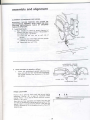
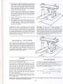
STEPFOUR
S O U A R I N GS A W B L A D E T O ( W O R K ) T A B L E
NOTE: lf alignmentprocedurestep onewas not performed,
this adjustmentcan not be accomplished.
1. Placea framing squareon the table with the short leg
againstthe saw blade.Do not allow the squareto rest
"set-out" tooth; it must rest flat againstthe
againsta
bladeside.
2. lf the saw blade is squarewith the table top (no visible
gap appearsbetween the saw blade and square)arld no
is required. Set bevel indicator to 0o
iolrti-.nt
reading.lf the squaredoesnot touch the saw bladeas
shown (with squareleg held firm againstthe tabletop),
performthe following adjustments:
WRONG
I
L O O S E NT H E S E
FOURSCREWS
a. Tighten carriage lock knob'
b. Remove handle cover by removing two #10 Pan
H e a d S c r e w s .R e m o v eh a n d l e b y r e m o v i n g5 / 1 6 - 1 8
socket head screw and lockwasher.
c. Loosen the four socket head screws with 114" Hex
"L"
Wrench. Rotate motor while holding square
f irmly against saw blade and table top.
d. Slightly tighten each of the four screwsand recheck
. . . Now tighten each screw tight.
e . R e i n s t a l lh a n d l e a n d a d j u s t i n d i c a t o ro n 0 o r e a d i n g .
f.
KIbN
s/16-18SOCKET
HEADSCREW
5/16 rN. LocKwASHER
Loosen carriage lock knob.
NO. IO PAN HD.
SCREW
S T E PF I V E
.
SOUARING BLADE TO RIP (GUIDE) FENCE
HEEL ADJUSTMENT.
IEFT HAND
C A R R I A G EC O V E R
BLADE
NOTE: lf alignment procedure steps two and four were not
performed, this alignment step cannot be accomplished'
1. Position carriage as shown and tighten carriage lock
knob. Place a framing square against the rip fence and
the saw blade, as shown. The long leg of the square
must be held firmly againstboth the fence and the table
top, and the short leg must not touch any o{ the teeth
on the saw blade. Check at several points of blade
rotation.
2.
R I PF E N C E
lf the square does not touch the blade at both of the
t w o p o i n t s a s s h o w n , a h e e lc o n d i t i o n e x i s t s .
l6
assemblyand alignment
3. To correct"heel" conditionproceedasfollows:
a.
b.
c.
d.
Removeleft hand carriagecover.
Loosenthe yoke clamphandle.
Loosen(slightly)the two hex-head
screws.
Rotate the yoke assemblyuntil gap between the
sawbladeand squareis eliminated.
e. Lock yoke clamp handle and retighten the two
hex-headscrews.
f. Recheckfor "heel" and installcarriagecover.
g. Loosencarriagelock knob.
N O T E : T h i s a l i g n m e n tp r o c e d u r ew i l l s i m u l t a n e o u s tsve t
b o t h y o k e i n d e x i n gp o s i t i o n sf o r b l a d ei n a n do u t r i p .
HEX HEADSCREWS
LEFTSIDEOF CARRTAGE
VE RTIC.AL HEEL ADJUSTMENT
1. With sawblade in 90o cutoff position. elevate saw and
rotate motor to vertical position (Blade Horizontal) and
check for heel. Make sure bevel lock lever is locked.
2.
Position square perpendicular to fence and between
blade and table, as shown lower arm. Do not allow the
square to rest against a "set-out" tooth, it must rest flat
againstthe blade side.
J.
l f t h e s a w b l a d e i s p a r a l l e lw i t h t h e t a b l e t o p ( n o v i s i b l e
gap appears between the saw blade and square), no
adjustment is required.
4 . lf there is a visible gap between saw blade and square, a
bevel heel condition exists and adjustment is required.
a. To correct, unlock bevel lock lever, loosen the rear
motor mount 3/8-16 nut until you can rotate Cam,
and then rotate Cam as shown until gap between
saw blade and square is eliminated.
b. Tighten nut and bevel lock lever and recheck.
c.
B e p o s i t i o nm o t o r i n c r o s s c u tp o s i t i o n .
I
TABLE
KIgN I
WRONG
(TURN CAM
cou NTERCLOCKWTSE)
t7
WRONG
(TURN CAM
c L o c K w IS E )
STEPSIX
1. INSTALLING AND ADJUSTING RIP SCALE
INDICATORS.
NOTE: The rip scalesand pointersare intendedto
be used for quick settings.For greateraccuracy,
take direct measurement
betweenbladeand fence.
indicatorand twin nut, loosenbut do
a. Pre-assemble
not removethe two screwswhich attach left hand
carriagecover.
b. Tilt carriagecoverand installrip indicatorasshown.
Tightencarriageattachingscrews.
c. Loosen but do not removecarriagelock knob in
right hand carriagecover.Installrip indicatorin the
samemanner.Tightencarriageattachingscrews.
d. With the fence in its normal position (next to the
front table),loosenthe yoke clamp handle,pull on
swivellatch pin knob and rotatethe yoke as shown
to index the yoke 90o from the crosscut position.
This will locatethe saw blade betweenthe motor
and the fence. Lock the yoke by tightening the
y o k e c l a m ph a n d l e .
IABLE SPACERBOARD
RIP SCALEINDICATOR
e.
f.
s.
Position carriage until the edge of the blade, when
spun by hand, just touches the front face of the
fence. The rip-scaleindicator (on the right hand side
of radial arm) should now read "0" inches on upper
portion of the blade "ln-Rip" scale. lf not, loosen
screws and shift the indicator until it is aligned with
"0"
the
mark, then tighten the screws.
NOTE: With the saw blade and fence in the position
shown, the upper portion of the blade "ln-Rip"
scale is used. lf the fence is re-located at the
extreme rear position, the lower portion of the
"ln-Rip"
blade
s c a l ew o u l d b e u s e d .
CARRIAGE
LOCK KNOB
The blade "Out-Bio" scale indicator on the left
hand side of the radial arm is adjusted in essentially
the same manner as the blade "ln-Rip" indicator,
except the blade should be as shown. With 2 inches
measured between the fence and the face of saw
blade, the rip-scale indicator should be positioneo
to read 2 inches on the upper portion of the blade
"OutRip" scale.
NOTE: With the saw blade and fence in the position
shown, the upper portion of the blade "Out-Rip"
scale is used. lf the fence is moved to rear position
(at the rear of rear table) the lower portion of the
"Out-Rip"
blade
scale is used.
Loosen the yoke clamp handle, pull on the swivel
latch pin knob and return the blade to the 90o
position.
2 ' ' - M E A S U R EFDR O MF E N C E
TO NEAREST
BLADEIOOTH
t8
assemblYand alignment
A L I G N M E N TO F S P R E A D E RF O R R I P P I N G '
GUARD OR
W A R N I N G : N E V E R P O S I T I O NT H E
NoR
wlrH PowERoN;
ir,r'iiiiickaAcKAssEMBLY
pdi;iioN-attrrlrrcreAcr PAWLsBY GRASPING
P A W L SO R S P R E A D E R .
2. Install BladeGuard.
of
a. Sight (visually)to check for proper alignment is
spreader
the
lf
shown'
as
blade
saw
ipieaOerwith
not aligned,adjustit asfollows:
(1) Loosen two hex nuts' one on each side of
sPreader.
(2) Rotate hex nuts with fingersuntil the spreader
is directlYin line with sawblade'
(3) Tightenboth hex nuts firmlY'
ANTIKICKBACK,SPREADER
WING SCREW
ADJUSTING
3. Checkand Adiust the spreaderasfollows:
spreaderadjustingwing
a. Loosen the antikickback
"tab" positionthe antikickback
the
screwand with
blade
and spreaderassemblynearthe bottom of the
a n dt i g h t e n .
PAWLS
ANTIKICKBACK
FENCE LOCATIONS
ripping
Position (A) .is used for most cutoff and narrow
width
oi"t.iionf. Position (B) is used for maximum
c
r
osscut
m
a
x
i
m
u
m
(
C
)
a
c
h
i
e
v
e
t
o
i
s
u
s
e
d
.
i i p p i n g .P o s i t i a
capacityin thin work.
your saw' you
Now that you have assembledand aligned
of this
controls.section
operating
proceecl
with
to
are ready
not
does
if
saw
section
manual. Refer to trouble shooting
problemsshouldsurfaceafter
anv
or
sitisfactorilv
;;;;;
usingthe saw.
B
rt
l9
C A
rl
rocationsand functions
of contrors
The versatility of the
Rad.ial Saw is due, in part.
to its
andthese
.r._lh1
:"^:::"lrt
,[:iilJ",.'::Jhe
t"v, io i"-rJJ..rrrr,operation.
controIs tot . rr op.ruiio-n"r"i"ro
r. actua
||y
A s e r i e so f s i x d i a q r a m
",m
**l.il' ;;:i.'i;l:"","..Xi1;;
*:,TS.'
:::ffiTJj:
set-ups and
!.
operatino
tamiliar with thesedia-qrams
,procedurer. io, Jf.lortd become
t h a t f o l l o w , b e f o r eo p e i a t i n gand the oo.i.,lni Instructions
y o u r, . * l - " , " . " , "
MITERSCALE
AND INDICATOR
5
2
ARM CONTROL
LEVER
BEVETINDEX L E V E R
RIP SCALEINDICATOd
o-rprx or cut
rdur
:g
-:l-:JLAOE
3
AilcL€ (AEv€L)
6
SWIVEL
LATCH LEVER
v r\-vrF
SWITCH
W I T HK E Y
POWER SWTTCHG KEY
A R ML O C K
ADJUSTING
WHEEL
TAELECLAMP
\
ELEVATION
CRANK
I
4
CARRIAGE
L O C KK N O B
3
YOKE LOCK
H,ANDLE
ANTIKtcK8ACK, SPREADER
ADJUSTING
WING SCREW
ANTIKICKBACK
AND SPREADER
ASSEMELY
BEVELINDEX
INDICATOR
7
ACCESSORY
SHAFT
locations and functions of controls
saw-blade(bevel) angle, are: bevel lock leverand
lever.
bevel-index
b. The bevel-indexscaleindicatesthe angularposition
of the motor with respectto horizontal,from 0o to
90o in eitherverticalPosition.
c. The bevel index lever automaticallyindexes the
motor at 0o, 45o and 90o. Move bevelindex lever
to the left while positioningthe blade,then release
it. At any other positionit doesnot engage.
d. The bevel lock lever locks the motor to the yoke
w h e n t h e m o t o r i s i n a n y p o s i t i o n .P u l l l e v e rt o
and pushto lock.
release
1 . Depth of Cut (Elevation)
a. The diagram shows the elevationcrank which is
usedto raiseand lower the saw blade.
b. Clockwise rotation raises the blade
counterclockwiserotation lowers it- One complete
turn of the handlewill raiseor lowerthe saw blade
1/16-inch.
2. Angleof Cut (Miter)
Proper Indexing Method - Experiencedoperatorsof
woodworkingequipment.suchasthis CraftsmanRadial
Saw, acquire the habit of indexing in one direction
only, whenevera new settingis madein preparationfor
a differentoperation.
Example: When moving the arm to a miter index
positionmoveit slightly pastthe desiredindex position,
t h e n r e t u r nt o t h e i n d e xp o s i t i o nc a r e f u l l yt o i n d e xa n d
lock. Yoke indexing and bevel indexing can be
a c c o m p l i s h e di n a s i m i l a r m a n n e r . T h i s i n d e x i n g
technique tends to neutralizeany stressesimpaired
upon saw components and contributes to the high
degreeof accuracy the saw is capableof producing
when operatedexpertly.
a. The arm control lever locks, unlocksand indexes
the arm for Left and Right Miter cuts.
radial arm has positiveindex positionsat 0o
The
b.
and 45o Left and Right. The arm is rotated by
pulling arm control leverto index releaseposition'
With arm control lever releasedthe arm will
automaticallvindex at 0o and 45o Left or Right'
After positioning arm to the desiredmiter angle,
pusharm control leverto lockedposition.
6. PowerSwitch and Key
a. Insertkey into switch lock'
b.
Insertfinger under end of switchleverand pull end
out, to turn switchon.
U N L O C K I N D E XR E L E A S E
c. Pushleverin - with thumb - to turn switchoff.
3.
Yoke Pivot (Ripping)
a. Two controls are used in this operation. They are:
the swivel latch-pin lever and the yoke clamp
handle.
b. A swivel latch lever automatically indexes the yoke
at each 90o position. Pull the spring-loadedswivel
tatch-leverforward to releasethis pin.
c. The yoke clamp handle locks the yoke to the
c a r r i a i e i n a n y p o s i t i o n . P u l l t h e h a n d l ef o r w a r d t o
releasethe yoke; push the handle rearward to secure
the yoke.
d'
4. Carriage Lock
The carriage lock knob is rotated clockwise to lock
the carriageon the radial arm. and counterclockwise
to releaseit.
crosscutting operations the
b. When performing
k
n
ob must be rotated
carriage lock
counterClockwise until the carriage is free to travel
a l o n g t h e a r m . T h i s k n o b s h o u l d b e t i g h t e n e du n t i l
the operator is ready to grasp the bevel index
handle and make a cut.
a.
5. Blade Angle (Bevel)
a.
The two controls used in angular positioning and
indexing of the motor, to provide the desired
2r
W A R N T N G : T H I S L O C K T N GF E A T U R E l S
PROVlDED TO PBEVENT UNAUTHORIZED
USE OF YOUR SAW. ALWAYS REMOVE THE
KEY AND KEEP IT IN A SAFE PLACE. TO
B ON END OF
REMOVE KEY, HOLD THUM
"OFF,, POSITION
L E V E R T O K E E PS W I T C HI N
A N D P U L L K E Y S T R A I G H TO U T .
W A R N I N G : F O R Y O U R O W NS A F E T Y A L W A Y S
"OFF" WHEN SAW IS NOT
LOCK THE SWITCH
t N U S E .R E M O V EK E Y A N D K E E PI T I N A S A F E
PLACE. . . ALSO IN THE EVENTOF A POWER
F A I L U R E { A L L Y O U R L I G H T SG O O U T ) T U R N
S W ] T C HO F F . L O C K I T A N D R E M O V ET H E K E Y
THIS WILL PREVENT THE SAW FROM
STARTING UP AGAIN WHEN THE POWER
C O M E SB A C K O N .
Spreader
-to
prevent kerf from closing in on sawblade and
possible kickback;
- to prevent "wrong-way feed". "Wrong'way feed" is
feeding the workpiece - when sawbladeis in a rip
position - into the outfeed side of the cutting tool
(sawblade, dado, molding head, etc.). the side
c o n t a i n i n g t h e a n t i k i c k b a c k / s p r e a d e r .T h i s c a n b e
extremelv hazardous becausethe sawblade may grab
the workpiece and throw it violently toward the nose
o f t h e g u a r d ( i n f e e ds i d e o f t h e t o o l ) . D a n g e r l a b e l o n
guard.
"Wrong-way
feed" occurs when the teeth themselves
cut, or attempt to cut, a kerf in the workpiece. This
"kickback"
which is generated by the
differs from a
sides (one or both) of the teeth, becauseof binding
between the fence (heel), pinching of the sides of the
sawblade (failure to use spreader),and/or inadequate
set of teeth of sawblade.
- to act as a partial guard regarding accidental contact
with the sawblade at the outfeed side when ripping,
and leading edge when crosscutting.
a. The blade guard is positioned by loosening the
guard clamp screw and rotating the guard so that
"nose" just
clears the workpiece as shown.
the
7. AccessoryShaft
accessories:
Useonly the following recommended
D r i l l c h u c k ,S a n d i n gd r u m ,a n d R o u t e ra d a p t e r .
CAUTION: The sawblade,dado, or cutting tool must
be removed from the saw arbor before using the
accessoryshaft. NEVER operate the saw with cutting
installedon both
tools (includingsandingaccessories)
endsof the sawarbor.
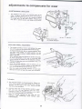
P O S I T I O N I N GG U A R D , A N T I K I C K B A C K A N D
A S S E M B L YF, O R R I P P l N G
SPREADER
W A R N I N G :N E V E R P O S I T I O NT H E G U A R D O R
A N T I K I C K B A C KA S S E M B L YW I T H T H E P O W E R
O N . N E V E R P O S I T I O NT H E A N T I K I C K B A C K
P A W L S B Y G R A S P I N G T H E P A W L SO R
SPREADER.
)
b.The antikickback and spreader assembly must be
adjusted to accommodate the thickness of the
board being ripped. A wing screw in the guard
Securesthe assembly.
GUARD
,-r-CLAUP
"
SCREW
t
IN F E E D
DIRECTION
+
)
/
MINIMUM
N O S EO F
GUARD GUARDCLEARANCE
1 . The blade guard is positioned by loosening the guard
D I R E C ITO N
OF KICKBACK
clamp screw and rotating the guard so that the nose iust
clearsthe workpiece as shown'
This is necessary:
- to protect operator from accidentally contacting the
sawblade radially from the Infeed direction.
-to
hold down the workpiece against the table minimizing lifting or fluttering (particularly thin
and/or I ight workpieces);
- to minimize sawdust thrown toward the operator.
- to minimize the possibilityof a thin pusher board
riding up on top of the workpiece with loss of control
of workpiece.
2.
f ccu
A N T I K I C K E A CPKO S I T I O N
3.
T h e a n t i k i c k b a c k a n d s p r e a d e ra s s e m b l y i s u s e d d u r i n g
r i p p l n g o p e r a t i o n s a n d i s a d j u s t a b l et o a c c o m m o d a t e
t h e t h i c k n e s so f t h e b o a r d b e i n g r i p p e d - A w i n g s c r e w
i n t h e g u a r d s e c u r e st h e a s s e m b l Y .
These adjustments are necessarY:
Antikickback
- to stop a kickback if generated.
22
Loosen the wing screw and with the tab provided,
position the antikickback and spreader assembly until
the pawl assumes approximately the position shown
above. Tighten the wing screw.
(Make sure by trial before starting the cut that the
antikickback pawls will stop a kickback once it has
started). Insert workpiece alongside spreader under
outer set of pawls by approaching pawls in the feed
direction. Push workpiece sharply in the direction of a
kickback (opposite to direction of feed). Readjust
Pawls if they do not stop the kickback motion by biting
into the workpiece.
)
j
HAVE YOUFOLLOWEDALLS'XSTEPSOF
THE ALIGNMENTPROCEDI'RE?IF YOU
HAVE NOT FOLLOWED THEM IIT rNfuN
PROPER SEQUEVCE, YO'I CENNbT
EXPECTACCURATECI'TTING NESUIiS.
In addition to, the proper alignment of your saw, you musr
a l s o b e c o m e f a m i l i a r w i t h t h e f o l l o w i n g p r a c t i c e si n o r d e r
to expect the best results.
I
t
THISEDGEOF BOARD
AGAINSTFENCEFOR ALL CUTS
1. Edge of workpiece which is placed against fence
m u s t b e a s s t r a i g h ta s t h e l o n g s i d eo f y o u r f r a m i n g
square.
2. Workpiece must be as flat as the front table board
on your saw.
3. There must be no sawdust or other wood chios
between the fence and front table board.
4.
There must be no sawdust or other wood chips
underneath workpiece or between workpiece and
fence.
5. Workpiece must be held tightly against fence . .
t h i s i s e s p e c i a l l yi m p o r t a n t w h e n m a k i n g a n g l e c u t s
becausethe workpiece has a tendency to move.
6. Always use the correct Sawblade for the Job . . .
Always keep it sharp.
7 . W h e n m a k i n g a f o u r s i d e df r a m e :
a. The two side pieces must be exactly the same
length.
b. The top and bottom pieces must be exactlv the
same length.
c. Always place the same edge of the workpiece
against, the fence
turn the workpiece end
for end for the successivecuts and mark a pencil
l i n e o n t h e t a b l e f o r g a u g i n gt h e r e q u i r e dl e n g t h .
Turn workpiece over end for end
keep same edge
against fence when making successivecuts.
2ND AND 4TH CUTS
P E N C I LL I N E F O R
G A U G I N GR E Q U I R ELDE N G T H
3RD CUT
SCRAP
D-eviations from any of the above practices will have
an
effect on the accuracy of the cuts that you make.
basic saw operations
i
I
t
Basic saw operations are summarized into six categories,
explained and illustrated in the following paragraphs.
A
book entitled "Power Tool Know How-Radial Saw,, is
available at your nearest Sears Retail Store or
Catalog
Store. This book contains considerable data applicable
to
t h e r a d i a ls a w .
| 3F":l?i
N . O T E : R e f e r t o p a r a g r a p h su n d e r , , O p E R A T | O N , ,
for
illustrations and descriptions of controls.
23
basic saw operations
REOUIREMENTSFORCROSSCUT
Board position (stationary) against rip fence (guide) and
l a y i n gf l a t o n t a b l e t o p .
(OPERATIONS 1 THROUGH 4}
1. Arbor nut must be tight and saw blade guard installed
i n h o r i z o n t a lp o s i t i o n .
2. Arm control lever must be in locked position.
3. Adjust the antikickback assemblyso the pawls just clear
the workpiece or the fence, whichever is higher.
4.
Work must be held firmly against table and fence. For
workpieces thicker than the fence is high, install a
higher fence (at least workpiece thickness). Always
place the fence in the most forward position (farthest
from the column support) compatible with the
workpiece being processed and the operation being
performed. With the carriage fully retracted. the blade
must not contact the workpiece when placed against
the fence, within the stated capacitiesof your saw.
5. Blade should be sharp and correctly set.
6. Hands must be kept well away from saw blade.
7 . Y o k e c l a m p h a n d l em u s t b e i n l o c k e d p o s i t i o n .
8. Bevel index lever must be locked.
9. Blade should cut into the table or plywood cover not
morethan 1/32 inch.
10. Pull the saw ,forward just far enough to sever the
l u m b e r . l t i s d a n g e r o u si f t h e b l a d e h a s b e e n p u l l e d t o o
far out beyond the piece being cut. When it is returned
it can pick up the right hand piece and throw it over the
fence.
11. For operations No. 3 and No. 4, observeadditional
"Operating
Controls"
instructions under paragraph
"Blade
Angle".
PROPER
(SEE ITEM "10" AT LEFT)
N o . 1 _ CROSSCUT
OPERATION
Crosscutting is the process of sawing the workpiece by
p u l l i n g t h e s a w b l a d e t h r o u g h it and using the fence as a
support for the edge of the workpiece. Never crosscut
free-hand.
DIRECTION
OF TRAVEL
W A R N I N G : B E F O R E C R O S S C U T T I N GM, A K E S U R E
T H E A R M C O N T R O LL E V E R , B E V E L L O C K L E V E R
A N D Y O K E C L A M PA R E A L L L O C K E D N
. E V E RU S EA
L E N G T HS T O PO R A F I X E D G U I D E O N T H E F R E E
E N D O R E D G EO F A W O R K P I E C ED. O N O T C R O S S C U T
W O R K P I E C ETSH A T P L A C EY O U R H A N D SC L O S ET O
THE PATH OF THE SAW BLADE. WHEN MORE
E X P E R I E N C EI S G A I N E D B Y U S I N G T H E S A W , I T
WtLL BE NOTICEDT
, H A T W H E NP U L L I N GT H E S A W
T ,H E B L A D E
T O W A R DY O U D U R ] N G C R O S S C U T T I N G
T E N D ST O F E E D I T S E L FT H R O U G HT H E W O R K D U E
TO THE ROTATION OF THE BLADE AND THE
D l R E C T I O N O F T H E F E E D . T H E R E F O R EY, O U
S H O U L DD E V E L O PT H E H A B I T O F H O L D I N GY O U R
R I G H T A R M S T R A I G H T F R O M T H E S H O U L D E RT O
THEWRIST.
24
IMPROPER
( S E EI T E M" l O ' ' A T L E F T )
NG
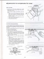
REPETITIVE CROSSCUTTI
"C"
clamp (min. 6 inch) usinga wood block on
Clamp a
e a c h s i d e o f t h e a r m . T h i s w i l l l i m i t t h e c a r r i a g et r a v e l
beyond the position necessary to complete the crosscut
operation.
basic saw operations
OPERATION
N o . 2 - M I T E RC R O S S C U T
Miter crosscuttingis the processof sawinga board at any
angleother than a 90o (square)cut. The 45o miter angleis
a popular one, since two boards cut to 45o can be
assembled
to form a 90o cornerfor producinga squareor
rectangularframe.The radial arm is set to the desiredangle
of cut; yoke and bevelsettingsindexedat 0o (andlocked)
as in squarecrosscutting.
The boardbeingcut is held firmly
againstthe fence (guide) and the carriagepulled forward
along the radial arm to perform the desiredcut. As in
"Operation
No. 1", the carriageshouldbe returnedto full
rear position and the saw blade allowed to come to a
completestop beforeremovingthe boardsfrom saw table.
OPERATIONNo. 3 - BEVELCROSSCUT
Bevelcrosscuttingis the processof sawingat 90o (sguare)
acrossthe board with the saw bladeset at an angleother
than 90o to the saw table. The radial arm and yoke are
indexedat 0o and locked,but the bevelis setto the desired
angleof cut. The board is held firmly againstthefenceand
the carriagepulledforward alongthe radialarm to produce
the cut. The carriageshould be returnedto full rearward
positionand the saw blade allowedto come to a complete
stop beforeremovingthe boardsfrom sawtable.
OPERATION o.4 - COMPOUND
cRosscuT
Compound crosscutting is the combination of miter and
bevel crosscuts.The radia, arm and bevel are set to produce
the desired cut; the yoke is indexed at 0o and locked. The
board is held firmly against the fence and the carriage
pulled forward along the radial arm to produce the cut.
Again. the carriage should be returned to full rearward
position and the saw blade allowed to come to a complete
stop before removing boards from saw table.
R E O UR
I E M E N TW
S H E NR I P P I N G
(OPERATIONS
5 AND 5)
1. Carriagelock knob must be locked.
2. Radialarm must be lockedin 0o position.
3. Work must be held firmly againsttableand fencewhile
feedingthrough.
4. Guard spreaderand antikickbackmechanismmust be
p r o p e r l y s e t . O B S E R V E I N S T R U C T I O N Sl N
P A R A G R A P H , " P O S I T I O N I N GG U A R D . A N D
A N T I K I C K B A C KA N D S P R E A D E R
A S S E M B L YF O R
RIPPING"UNDER "LOCATION AND FUNCTION
OF CONTROLS".
5. Bladeshouldbe sharpand correctlyset.
6. When ripping narrowstock,lessthan 3 inchesbut more
than 1/4 inch betweenthe guardand the fence(guide),
usea "Push Stick" at least1l4" thick and at least16"
long so the workpieceis clearof the bladebeforeyour
handcontactsthe guard.
GREATER
THAN r/4"
S L I G H T I YL E S ST H A N
T H I C K N E SOSF W O R K P I E C E
uP TO 3/8"
7. When ripping stock 1/4 inch or less between the blade
and fence (guide) use a Pusher Board.
Pusher board should not be lessthan 3 incheswide and
1 6 i n c h e sl o n g . N a i l o r g l u e a 3 / 4 x 3 / 4 x 4 i n c h b l o c k
to one edge of pusher board to be used as a grip.
The pusher board should be fed into the blade behind
t h e s t o c k b e i n g r i p p e d u n t i l t h e s t o c k i s c l e a ro f t h e r e a r
of the blade (not more than 8 inches so as not to strike
antikickback pawls) and then pulled back with use of
t h e g r ip .
8 . H a n d sm u s t b e k e p t w e l l a w a y f r o m s a w b l a d e .
9. Saw blade MUST be parallel to fence, to minimize
possibiIity of kickbacks.
10. For every new width of cut, a new PUSHER BOARD o r a r e w o r k e d P U S H E R B O A R D t o r e m o v et h e m a t e r i a l
c o n t a i n i n gt h e k e r f - m u s t b e u s e d .
blp
1 1 . T h e o u s h e r b o a r d s h o u l d b e t h e s a m e t h i c k n e s sa s t h e
workpiece. No thinner for strength, or no thicker since
the nose of the guard must clear the top of the
w o r k p i e c ew i t h m i n i m u m c l e a r a n c e .
1/4" OR LE55
N o .5 - O U T - R I P P I N G
OPERATION
AND IN.RIPPING
1.
-
W A R N I N G : N E V E R R I P F R E E . H A N D .B E F O R E
R I P P I N G , M A K E S U R E T H E G U A R D ,A N D
A N T I K I C K B A C KA N D S P R E A D E RA S S E M B L YA R E
. LSO.MAKE SURE THE SAW
S E T U P P R O P E R L YA
B L A D E I S P A R A L L E L W ] T H T H E F E N C E .N E V E R
R I P W O R K P I E C E SS H O R T E RT H A N T H E S A W
BLADE DIAMETER.
Ripping is the process of sawing the workpiece by
feeding it into the saw blade when using the fence as a
guide and as a positioning device to obtain the desired
width of cut. The sawblade is oarallel to the fence.
26
2. Sincethe work is pushedalongthe fence,it must havea
straightedgein order to make slidingcontactwith the
fence.Also, the work must makesolidcontactwith the
table, so that it will not wobble.Providea straightedge,
e v e n i f t h i s m e a n st e m p o r a r i l yn a i l i n go f a n a u x i l i a r y
straight-edged
board to the work. lf the workpiece is
warped,turn the hollow sidedown.
3. Always usethe sawguardand makesurethe spreaderis
correctly alignedwith the saw kerf and antikickback
pawls properly adjusted.Woodcut with the graintends
to spring the kerf closed and bind the blade and a
kickbackcould occur.
4 . Stand a little to one side of centerto be clear of 'work
in caseof kickback.
5 . When rippingshort or narrow work, alwaysuse a push
stick appliedto the sectionof the workpiecebetween
the blade and fence. . . pushthe work pastthe bladeso
e i l l m i n i m i z et h e
i t i s c l e a ro f t h e b l a d e .T h i s p r o c e d u rw
p o s s i b i l i t yo f k i c k b a c k s .
In-Ripping.The radialarm and bevelare indexedat 0o and
locked, but the yoke is turned 90-degrees
in a clockwise
direction (viewedfrom above)from the crosscutposition.
Thus, when standingin front of the saw,the bladewould
be rotating counterclockwise.
After positioningthe guard
and antikickbackmechanismthe workpieceis fed from the
right-handside of the saw. The "Blade In-Rip" scaleis on
the right-handsideof radialarm.
Out-Ripping.The radial arm and bevel are indexedat 0o
and locked, but the yoke is turned 90-degreesin a
counterclockwise
direction (viewedfrom above),from the
crosscutposition.Whenstandingin front of the saw,blade
would be rotating clockwise.After positioningthe guard
and antikickbackmechanismthe workpieceis fed from the
left-handside of the saw.The"Blade Out-Rip" scaleis on
the left handsideof radialarm.
O P E R A T I O N o . 6 - B E V E LR I P P I N G
Bevel ripping is either in-ripping or out-ripping as described
above, except the saw blade is tilted out of perpendicular to
the saw table surface. The radial arm is indexed at 0o and
locked, the bevel is set to the desired bevel angle and the
yoke is positioned for in-ripping (saw blade at rear) or
(saw blade at front), as required. All
out-ripping
requirements and observations applicableto normal ripping
operations also apply to bevel ripping.
DADOING
MOLDING/SANDING
Instructions for operating the Dado Head are contained in
booklet furnished with the Dado Head.
The saw arbor is designed for dado heads up to 13/16
inches wide. Do not install a wider dado head on the arbor.
Take severalpassesif required dado cut exceeds13/16 inch.
When installing the dado head on the arbor, ALWAYS
install the inside "loose collar" first. Be sure the teeth of
the chippers are placed to fall in blade gullets,and chippers
are approximately equally spaced around the arbor.
DO NOT install the outside loose collar. Make sure the
arbor nut is tight. Install the arbor nut directly againstthe
outer blade of dado head.
For best results and to avoid excessiveload on the motor,
NEVER CUT A 13/16" WIDE DADO. DEEPER THAN
3/4" IN ONE PASS.
Instructions for operating the Molding Head are contained
i n a b o o k l e t f u r n i s h e dw i t h t h e M o l d i n g H e a d .
For use of Molding Head Cutter or Drum Sander the rear
table reqr.Jresan opening (next to rear face of fence) for
clearance.Cut this opening as shown.
REARTABLE
N E V E R U S E A D A D O H E A D O R M O L D I N GH E A D W I T H T H E S A WA R B O R V E R T I C A LW I T H O U TI N S T A L L I N GA N D
A D J U S T I N GA M O L D I N GH E A D / D A D OG U A R D .
27
adjustments to compensate for wear
ADJUSTING BEVEL LOCK LEVER
r--=-\.
1. The purpose of this lever is
to lock the moror at any
angle. To adjust, remove the set
screw with wrench as
shown. Use the bevel
lever
as
, *r.n.n to tighten
-lock
the clamp bolt. Do Not
Over fight"n. R'.ptace bevel
lock lever in locked position anO
ilgl_,t"n the 5s1sqrsM/.
\
N
EEVELLOCK
LEVER
w
/
E
V
I
I
t/8 HEX ''1" WRENCH
EEVELLOCK LEVER
I N L O C K E DP O S I T I O N
YOKE LOCK HANDLE ADJUSTMENT.
1. This handleprovidesa friction lock
betweenthe upper
face of the yoke and the bottom lr"" tiii,"
carriage.
It should eliminateany play or rotation
betweenthese
two parts when locked. lts proper position
for saw
o.perationis gpproximatelymidway U.t*..n
the two
sidesof the yoke.
When sufficientwear has occuredto permit
the handle
to move considerablyto the rear. or strike
the Voke
before locking,the handlemust be adjuileO
as follows:
2. Removecarriagestop screwand lockwasher
with a ,l/4
i n c h h e x - Lw r e n c h .
3. Grasp-thecarriageassembly,move it carefully
off the
. n d . . o l r a d i a la r m , h o l d i n gi t p a r a l l e l
t o t t r ei a O i aa
t rm
until all carriagebearings
aie free ot their i...t r.
Rest the motor and carriageassemblyon
saw work
table and re-installcarriagestop scre* .nJ
io.r*.rh"r.
HEX '1., WRENCH
(l/4 tNcH)
- t
"/
CARRIAGE
STOP
SCREW
To Readjust
Sg, Vgi1. lock handleat unlockedposition.
Tightennut
untirrock;;;ii;j;;k;,
lljl.
illlgthe wrench.,
oetween
two
rsll6 wRENCH
mid_way
sides of the yoke. nemoue carnage
stop screw and lockwasher.
7.
H o l d t h e m o t o r a n d c a r r i a g ea s s e m b l y
p a r a l l e lt o r a d i a l
arm.and start the rear bearings
onto the tracrs.
Continue to hold the assemblyparallel
to the tracks
until the forward bearingsare
on the tracks.
9lld^"_-,1. carriage rearward on the radial arm and
SrOPSCREW
:LIOI TC.KAW! LA_SrHHEER .C A R R | A G E
AND
28
adiustmentsto compensatefor wear
ARM TO COLUMN
1. With the arm control lever unlocked and in index
releaseposition,the arm should move firmly with no
verticalplay in the arm.
The arm shouldfit snuglyon the column. lf not. then
adjust.
a. Removetwo (2) screwsfrom rear cover plate and
tighten evenly top two 3/8-16 bolts, until arm
movesfirmly and there is no verticalor horizontal
movementin the arm when arm control lever is
l o c k e do r u n l o c k e d .
b, Bottom two nuts shouldbe snuggedevenly,but not
nearlyastight astop two bolts.
c. Be-lnstallRearCoverPlate.
d-
A D J U S T I N GC A R R I A G EB E A R I N G S
In proper adjustmentthe top and bottom radii of all four
bearingsshouldbe in contact with the arm tracksfor their
entire lengthand carriageshould roll freely but with some
resistance.
To test for looseness
betweenbearingsand trackson radial
arm,performthe followingsteps.
1. Removeleft-handcarriagecover.
2. Pushthe carriageto its full most rearwardposition.
3. Finger hold front carriagebearingas shown and apply
as much force as possibleand at the same time pull
carriageforward. lf you can stop the bearingfrom
turning it will requireadjusting.
4. Check rear bearingin the same manner and adjust as
follows:
a. Loosen nuts just enough to permit the eccentric
screwsto turn.
b. Rotate the eccentricscrewsa oartial turn (left or
right) as requiredto take up looseness.
c . Hold the headsof eccentricscrewsin the position
establishedin the precedingstep and tighten nuts
on undersideof carriage.Correctadjustmentexists
when you cannot keep the bearingsfrom turning.
However, excessivebearing pressure will cause
d i f f i c u l to p e r a t i o na n d r a p i dw e a r .
d . I nstallcarriage
cover.
WASHER
ASSEMBLY
ECCENTRIC
SCREW
CARRIAGE
CARRIAGE
BEARING
PLAIN WASHER
LOCKWASHER
NUT
29
A R M L O C KA D J U S T I N GW H E E L
Arm control lever operatesa brake shoe that locks and
the arm index
releases
the arm, and automaticallyreleases
pin for 0o & 45o miter settings.
The lock action shouldfeel tight and secure.Considerable
amount of effort must be appliedto the leverto lock the
arm.
N O T E : L e v e rm u s t b e i n u n l o c k e dp o s i t i o nw h i l e m a k i n g
adjustment.
lf adjustmentis required,turn arm lock adjustingwheel
under front of the arm clockwise to tighten, counterclockwiseto loosen.
ARM INDEX ROD ADJUSTMENT
At some time it may be necessaryto make an adjustment to
the Arm Index Rod, to compensate for wear in the
I n d e x i n gS y s t e m .
LEVERARM KNOB
M I T E RI N D I C A T O R
An indication that this adjustment must be made is when
one of the following occurs:
IMPORTANT: ARM LOCK/ADJUSTING WHEEL (SEE
ABOVE) MUST BE PROPERLY ADJUSTED AT THIS
TIME.
1. With the arm control lever pulled forward and held
"lndex
R e l e a s e "p o s i t i o n , t h e a r m c a n n o t b e
in the
moved out of the Indexed position. (lndex pin not
f u l l y r e t r a c t i n gf r o m l n d e x r i n g ) .
2 . W i t h t h e a r m i n o n e o f t h e I n d e x p o s i t i o n sa n d t h e
arm control lever allowed to rest in the Unlocked
position (with the column tube supports and gibs
adjusted properly eliminatingall play in this area).
A slight side to side movement is noticeable at the
front of the arm. (lndex pin not fully seated in
IndexRing).
\
r*trenscn-r
,/\
-"'1-b
Y
'*
I
o
ARMTRIM
ARM TRIM
PAD
ARM CONIROL
LEVER
CARRIAGE-
E
^L
:
STOPSCREW
To make an adjustment to the arm Index rod the following
steps must be taken.
1 . R e m o v i n gA r m T r i m ( S h r o u d )
a . R e m o v em i t e r i n d i c a t o r . S n a p f i t .
b. Remove miter scale by removing two #10 Pan
Head screws.
c. Remove knobs from arm control lever.
d. Remove stop screw and lockwasher in arm.
R e m o v e c a r r i a g e .R E - I N S T A L L S T O P S C R E W
AND LOCKWASHER.
e. Grasp arm trim and remove.
f. Remove arm trim pad.
6
CARRIAGE
2. Adiusting Index Rod.
a. Loosen carriage bolt and nut which holds
adjusting bracket in place.
b . P o s i t i o na r m i n 0 o l n d e x .
c. Bring adjusting bracket forward until it is
approximately 1/16 inch from contacting Index
rod. Or until it is in the extreme forward
position on the mounting slot.
d. Tighten carriage bolt & nut. Test indexing
action in all Index positions.
parts that have been removed.
Reinstall
3.
a . I n s t a l la r m t r i m p a d .
BRACKET
ADJUSTING
Remove Carriage Stop Screw and Lockwasher
and install carriage.REINSTALL CARRIAGE
S T O P S C R E W .A N D L O C K W A S H E R .
c . I n s t a l ll e v e ra r m k n o b .
d. Install miter scale and miter indicator. Set miter
indicator to 0o.
b.
r/r6-lNcH
30
trouble-shooting
F I N I S HC U T E N D
l$'$
1. RADIAL SAW DOES NOT MAKE ACCURATE 0o or
450 MTTERCROSSCUTS.
a. Looseness between column tube and column
support.
Align as describedin Alignment'procedure
Section
Step Two.
b. Crosscuttravel not properly adjusted.
R efer to Step Three in Alignment procedure
SectionSquaringCrosscutTravel.
c. Column is Loosein Support.
Referto StepTwo in Alignmentprocedure.
,\\'\\
\\\\\
F E N C EE D G E
F E N C EE D G E
F I N I S H C U T L O O K S L I K E T H I S _ O OC R O S S C U T
d. Arm Not IndexingProperly.
R e fe r t o A r m I n d e x R o d A d j u s t m e n t i n
Adjustmentsto Compensate
for Wearsection.
e . CarriageAssemblyLooseon Arm.
Refer to CarriageBearingAdjustmentin adjustment
to Compensate
for WearSections.
f. Looseness
betweenYoke and CarriageAssembly.
Refer to "Yoke Lock Handle" adjustment in
adjustmentto Compensate
for WearSection.
OR LIKE THIS - 45O MITER.
g.
SawdustbetweenWork Pieceand Fence.
KeepFront Work TableClean.
h . Rip FenceNot Straight.
ReplaceFence.
2. SAW CUTS AT ANGLE _ NOT 9OOTO TABLE TOP.
SHOULD
B E9 0 "
ANGLE
a. Table support channelsnot properly leveled.
Refer to Step One under Alignment procedure
Section.
b. Blade not squareto work table top.
Referto Step Four in AlignmentprocedureSection.
3. B L A D E A N G L E ( B E V E L )C U T SN O T A C C U R A T E .
a. Corrective Action is the sameas paragraph2A and
B above.
b. CarriageBearingsLoose.
Referto adjustingcarriagebearingin adjustments
to
compensate
for wearsection.
c. Bevel Lock Handle Loose.
Refer to Adlustment Bevel Lock Handle ln
Adjustmentto Compensate
for WearSection.
4. SAW KERF (CUT EDGE} OF STOCK ROUGH _
TOOTH MARKS LEFT ON EDGEOF SAW KERF.
FENCE
wlDEcuT-
R O U G HK E R F
N O T E : T h i s c o n d i t i o ni s c o m m o n l yc a l l e d" H E E L " .
b. BevelCrosscuttingOr BevelRipping.
Refer to Step 5 Under Alignment ProcedureSection
VerticalHeelAdjusting.
Using lmproper Bladefor FinishCut Desired.
UseProperSmoothCutting Blade.
F I N I S HC U T E N D SQUARE
,/l\\\l
WARNING: REMOVE POWER CORD FROM POWER
S O U B C EB E F O R ET R O U B L ES H O O T I N G .
NOTE: Changingone adjustmentwill effect another,so it is
best to perform all of the alignment procedureswhen
correctingany one problem.
The usual operating"troubles" are listedin the following
paragraphs
with the necessary
correctionslisted.
Crosscuftingor Miter Cutting
"Heeling"
w i l l t e n dt o s l i d et h e w o r k p i e c ea l o n gt h e
guide fence,as the cut is beingmade,and make a
squarecut almostimpossible.
Refer to step 5 underAlignmentProcedureSection
- "SquaringBladeto Fence."
SQUARE
Fl'r/: c
(KERF)
- -
--=
-
D I R E C T I OO
NF
ATTEMPTED
BLADE
TRAVEL
B L A D E' , H E E L I N G , .
D I R E C T I OO
NF
BLADE
TRAVEL
--
trouble-shooting
I N RIP POSITION
5. WOOD
BINDS, SMOKES AND MOTOR SLOWS
DOWN OR STOPSWHEN RIPPING.
a. Dull blade or warpedboard.
Sharpen or replace the saw blade. Avoid the
attempteduseof severlywarpedmaterial.
b. Feed rate too fast.
Slow Feed Rate.
T O P V I E W W I I H ARM 9OO TO THE FENCE
/ \ -
\-l
FENCE \I
FEED
DIRECTION
<-
c. Saw blade heels.
C h e c k a n d a l i g n a s d e s c r i b e di n A l i g n m e n t
ProcedureSection,Step Five.
d. Fence not straight.
Replacefence.
e. CarriageAssemblyLooseon Arm.
Refer to adjustingcarriagebearingsin adjustments
to compensatefor wear section.
6. B O A R D P U L L S A W A Y F R O M F E N C E W H E N
RIPPING.
a. Saw Blade has heel.
Corrective action is the same as preceding
instructionsexplainedin paragraph
c.
7. W O R K P I E C ES T R I K E SS P R E A D E RW H E N R I P P I N G .
a- Adjust spreaderper instructions in Step Six under
"Alignment of Spreaderfor Ripping".
8. SAW DOES NOT TRAVEL SMOOTHLY ON ARM
TRACKS.
a. Dirty tracks.
Clean Tracks.
b. Bad Bearing.
ReplaceBearing.
c, Worn Tracks
ReplaceTracks
9 . C L A M P I N G F O R C E N O T S U F F I C I E N TA T M I T E R
ANGLES OTHER THAN 45O.
a. Arm Control LeverrequiresAdlustment.
Refer to Arm Lock Adjusting Wheelin Adjustments
to Compensatefor WearSection.
1 0 .C L A M P I N G F O R C E N O T S U F F I C I E N T A T B E V E L
ANGLES OTHER THAN 45O.
a. Bevel Lock LeverRequiresadjusting.
Refer to Adjusting Bevel Lock Lever in
Adjustments to Compensatefor WearSection.
32
H E E LT O R I G H T :
INCORRECT
H E E LT O L E F T :
INCORRECI
CORRECT
1 1 .D E P T H O F C U T V A R I E S F R O M O N E E N D O F
WORK PIECETO THE OTHER.
a. Table Top not parallel with Arm.
Refer to Attaching and Levelingtable Mtg. Support
Channelsin Step OneAlign. Section.
12. BLADE TENDS TO ADVANCE THRU LUMBER TOO
FAST.
a. Dull Blade.
Replaceor sharpenblade.
b. Not advancingSaw Blade properly.
Draw Saw Blade across lumber with a slow and
steadypull.
CHART
MOTORTROUBLE'SHOOTING
particularly
tgt
NOTE:Motorsusd on wood-working -"I: woodchips
to tne accumu'|il;;isivdust'anO
susceptible
to
ot '"""'umed"',frequently
and shouldbe blown-oit
ventilatton'
motor
with normal
il;";;i;;"rence
REMEDY
SUGGESTED
Motor will not run.
1. ProtectoroPen;circuit
broken.
2. Low voltage.
Motor will not run and
"BLOW".
fuses
Motor fails to develoP
full power. (Poweroutput
of .otot decreasesraPidlY
with decreasein voltage at
motor terminals.For
examPle:a reductionof
10/o in voltagecausesa
reduction of 19%in
ma<imum Poweroutput
of which the motor ts
capable,while a reduction
ol 2V/o in voltagecauses
in
a reduction of 36o/o
maximum Poweroutput')
Motor overheats.
lUotor starts slowlY or
fails to come uP to full
speed.
Motor stalls(resulting,in
blown fusesor trlppecl
circuit breakers)-
Frequent oPeningof
tusei or circuit breakers'
1. Short circuit in line,
cord or Plug.
2. Short circuit in motor or
looseconnections'
line'
3. lncorrectfusesin Power
1. Powerline overloadedwith
and other
lights,aPPliances
motors.
wiresor circuit
2. Undersize
too long3.
-' Generaloverloadingof
oo*"t company'sfacilities'
iln rn"ny sectionsof the
country, demandfor
electricalPowerexceeds
the capacityof existing
and distribution
generating
sYstems.)
on red.button'
1. Resetprotector by pushing
(indicatedby
motor
of
top
on
located
audibleclick).
proper voltage'
2. Check power line for
plugfor damaged
l.'- lnspectline, cord and
insulationand shortedwires'
fgr.looseor.,-^-2. lnspectall terminalsin motor
on wrres'
insulation
worn
or
terminals
;.f,;
3. lnstallcorrectfuses'
1. Reducethe line load'
lengthof wiring'
2. lncreasewire sizes,or reduce
3. Requesta voltagecheck
from the power company'
1. Slow down rate of feed'
feed ratewhen
1. Excessive
crosscuttingor rlPPlng'
(Air
2. lmProPercooling'
circulation restrlcteo
through motor due to
sawdust.etc.)
"heel"'
3. Saw bladehas
provide normal air
2. Cleanout sawdustto
motor'
through
lation
circu
Sectionof
3. Refer to Alignment Procedure
1. Correct low voltagecondition'
triP
1. Low Voltage will not
s,witch.
starting
condition'
1. Correctthe low line voltage
1. Voltagetoo low to permlt
motor to reachoPerattng
speed.
2. Fusesor circuit breakers
do not havezufficient
caPacitY.
with
2. Replacefusesor circuit breakers
nits'
u
pto-petcaPacitY
1. Reducemotor load'
breakers'
2. Replacefusesor circuit
1. Motor overloaded'
2. Fusesor circuit breakers
do not havesufficient
caPacitY.
33
maintenanceand lubrication
MAINTENANCE
N O L U B R I C A T I O NR E O U I R E D
W A R N I N G : F O R Y O U R O W N S A F E T Y ,T U R N S W I T C H
"OFF"
A N D R E M O V E P L U G F R O M P O W E RS O U R C E
OUTLET BEFORE MAINTAINING OR LUBRICATING
YOUR SAW.
When you receive your new Craftsman radial saw, it
requiresno lubrication.The radial saw has been partially
alignedand all bearingsare lubricatedand sealedfor life. In
time, however, in order to keep your saw in perfect
working order and accurate,it will be necessary
to lubricate
and realign. In fact, your radial saw needs more of a
cleaning
t h a na l u b r i c a t i o n .
Do not lubricatecarriageball bearingsor motor bearingsas
these are sealed ball bearings and require no added
lubrication.
Do not lubricatebetweenradialarm cap and radialarm.
P E R I O D I C A L L YL U B R I C A T ET H E S EP O I N T S
Use SAE No. 10W-30automotiveengineoil and refer to
PartsList for locations.Apply a few drops of oil alongthe
swivel latch pin and bevel index pin only if the pin has a
tendencyto stick. Removethe left-handcarriagecoverand.
use oil sparinglyto prevent it from getting on the ball
bearingsor races.
A light film of oil should be wiped on the face of the
column tube to lubricatethe fit betweenthe columntube,
and column support.
Make sure the teeth of the ANTI KICKBACK pawls are
alwayssharp.Replaceif not sharp.
LUBRICATION
The thread on the elevation shaft assembly can be
lubricatedthrough the oil hole in the centerof the radial
arm cap.
Your saw is precisionbuilt and should be kept cleanand
properly lubricated.Before describingthe variouspoints
w h i c h m a y p e r i o d i c a l l yr e q u i r el u b r i c a t i o n ,l T l S M O R E
IMPORTANT TO FIRST MENTION THE VARIOUS
P O I N T SW H I C HS H O U L DN O T B E L U B R I C A T E D .
CAUTION: Excessive oil at any location will attract
airbornedust particlesand sawdust.
recommended accessories
CAT.NO.
ITEM
Stand
S t e eL le s s
...::.:::::.::::::
Casters
KeyChuck
*Molding
HeadGuard- 7-inch
*Molding
HeadGuard- f-inch
R o t a r y S u r f a cPel a n e r - C a r b i d e T i p
S a n d i n g W h e e l8- - i n c h
SandingWheel- lO-inch
D u s t C o l l e c t o. r. . .
D u s t C o l l e c t o. r. . .
TaperJig
*Satin
Cut Dado- 7-inch .
*SatinCutDado-8-inch.
*Molding
H e a dS i n g l eC u t t e r
*Molding
HeadThreeCutter
SandingDrum - 3-inch
o Lower RetractableGuard .
"Power
Tool Know How Handbook"
RadialSaw
....9-222Os
...9-22208
.9-2980
. . .9-29524
. . .9-29523
.... 9-29513
. -.9-2274
.9-22723
.....9-16998
....-9-29517
...9-3233
. .9-3257
..9-3253
9-3215
9-3221
. .5-25246
9-29009
9-2917
*Before purchasing
or using any of these accessories,
read
and comply with additionalsafetyinstructionsNo. "(D)2"
on p. 4 of this manual.
.Meets OSHA Requirements
asof 8-73.
The above recommendedaccessories
are current and were
availableat the time this manualwasprinted.
34
repair parts
PARTSLIST FOR CRAFTSMANlO.INCHRADIAL SAW
MODEL 113.197751
o
s
4
6-
ll
&-
t2
o;;f;,
o
a
o
o
o
FIGUREl_LEGSET
Key
No.
1
2
4
E
o
7
I
o
10
11
12
*
Part
No.
63749
60314
63751
63750
sTD 551225
sTD 541025
sTD 523106
sTD 551031
sTD 55'l131
srD 541231
sTD 541250 |
803835
I
63752
I
Description
Leg
x5/8
Screw.TrussHd. 114-2O
Stiffener,R.l-.|.
Stiffener,L.H.
*Lockwasher,External1/4
*Nut, Hex 114-2O
*ScrewH
, e x H d . 5 / 1 6 - 1 8x 5 i 8
* W a s h e r1,1 1 3 2x 1 1 / 1 6x 1 / 1 6
*
External5/16
Lockwasher,
* N u t . H e x J a m5 / 1 6 - 1 8
*rurt, Hex Jam 112-13
Foot, Leveling
g.S of LooseParts(Not lllustrated)
Locally'
StandardHardwareltem - May be Purchased
35
repair parts
rr
U
/i
F
=
@
-1 r.o
<tN
Ob)
(\lc)
!t
rt
< (|)
r
cc
ln
9o
=z
o<
t
t
I
ln
t
:\
*--\
€
!t
t
F_=._
= N
<1. ct)
Jj
CO
yE) -o
-\
I
./i'
<E
o
3
I l
n
1-0@ @ i
CUJ
(Jco
EE
of
uZ
0DE-3
/
T
oa
ro
I
t
-d$
€
c-a
-fl- N
I
0i
O
ij
,
s--0-{
CD
-'i UJ
o
=o
tEr E
I
I
o-
I
/
/
,/
i'Iil
\
\
\
Affi_ATn
\
UH
r-W
l l l
J
C
D
N
\
\
\
\
9
!t
-----o-
I
(t
=
s
6b_q
p1o
\
-
36
1
o
l
o
lr
__6
(*
6
- - 7 ^
(\I
(')
CL
a,
o
o
{
I
frE€E
(o
EE-+E
"g
n
;
sSs ZZZ=,
:;
*S
ti
or
dg;.=e
ee?=i
,-l-r
*^;?
:
F
) x
xO
*ql
\ s
rl) \
x
s v
e sf :f
. : I e i r * E i F : ' - --E= * = * ' * €
6 d : 9 5 * E T ; # ; F E : f f f 6 & E f iH g
=:iii p
pi s$! !.;gg:.Fq?t?t-=€Ei'i #FgSggsBsB
s.t5coE
= . n,t32?pE
r\C
.L
P 3
3
6 .-
AR
o5
< i
E E : s p eI
-t
E2
eFEnngn;E
;EEBilgEEAAfi$$E
Ip
I
6<
Is
z
r
N
€5
5
(9
o;
=z
=t\
E
g 9P
i!;
f( Jfafo
E>
?.=
F J
vr!'/.J
rR
P=
5
CL
'A
-e
:
L
z
E
o-
)
A
(O
C., Ct an @ U) a/)
CL
RNRREESgsgSSSg
UJ
I
E
o)
sl
N
l
X
;
;
9
-
C'
@
C
o
X
to
E
(
sO
T
-i+
-,
T
i -E
i 9:;
fl :-t^R
PEF, SsSs--{
-3_ ^s
g)
eco
:-<
i;
(\r
cb
E
o
3
S
@
x
F
d = 1 5 8- c . : . >
;
R
-{
(n
.?
ErES!;:Q*b.rAE b -;
E€tEEe.aSFq
E ;r ; - :9 > r - :E:iEqE;
>
-
.
a
i
t l e E3 #
: ; : r !
6
- .,'B
F = :
L - ( J ( J
6 e , . ; 3 <. u) u)
=Ei;FFcFEIgi$FFF
8
D : : E B
;E$SEE
N*CE;$;EH;s
e c . ({ ' ) < r f ,( or \ @o )3 :
37
l::5
9:3I
RF NRXR
repair parts
/P-3
,'^f-e
t u )
{ r t
\
b-Z*
R--e
\
/
4-,F
/
.
/
=
CN
\\
.D
Ob
o
\
\\\
rtuo+)
\' \
9;
=z
o
<
FF
\------\
=E
Ei
/
/
./-\ \
/
;
/
\\Ii
. ' , a \\" \\
<r
EFi
r=
/
/
1
\(@' /' p*G
*-(,:1
/
,/
W
C1
dF
/
-/.F\
\
/
\ z N9-s
\_/ ffi>ks ? ; 3 3h
U
-/V/ * 9 l tt l/\\ l t l t
I
,l-.
^
s r
l l
er
o
<t
/6)(d.-.
("d"7i-
,'
[
tI
4--r . _-l
4
|
_\D4\2l J_
__4v_ _
F'
5-m
zffiP ?yrf*- d;r\d-e$dd
s/nir\"FN
rw:l\\ w,
//^
+E-\\)qjl-?tT
/'
I I \
nmr $-Mre
' ou ; r y f f i \ g A }
/
(
i2
om
Ea>
v,i
fR
P
=
tE
f
{i'rV-l
\^ \\ \.\ *. '
r\ . \' q \+-\ s. t\,
LI*-UHJ
"\
L-J
ltr\//\ V
=
*-ffir\
\t,. l/
e$\
\\'//-
o
8-€'-"qA'
---,
.--{-C
A
3'%
:-)a"
Ier.t----....-.G,1-
Et-*t t
{
-
e
*/
".2\fr
;/@
E-
",.
e'
I
=tfr'ffbo:o-ffi^-H)**o-it".,,
\
S E
\
\
\
t\
6l
)
h
c,
-e
.\ f
N
ff
/
E
o
{;";
iE;
E€#
g9g
i . HE
!: 'qe I:
E-cr;
=9
;
i -g
o,-/oPST'iqW\:
:F eo 'i6
N
,'t-Fry-t:\r
*P-?roqq
';
/ ,L2/>PeRVff\
i€3
i*J * ,/& -.+#?
Eg:
Tl''\=fff'tY1T-T%'i
-*3
s= -
ll\\lY
llllll
S = 9 i c i x € 6 r t ( t c { -
38
P
E
P
N \
$
(o
o
CL
(t
(l'
o
9S
x
N
i
i?
I
=S
x
S
:
lcr
o
:
cc
o..d
T ::_
( ; " 1
N : i
3
< ; g
i
: ; Ei E€ i S ;Ii s
a
-^'fFi ^E*rt E F F € € ; S : E F
i a g o e : Ir Ii X=' . , iI.B- ; €d SEF : r ; - . d E'F.
:8 ; a. €:
e
Fii
-'- o
o.C !,
o X o
= ;,P
;.:
i'' E
i.9t#i
, t8.di= H-i$
- E
.
i
?q€F,
i;F!
i:;E;i:€€
tqq:c€
t:s
r *; - ^ .*
* E E f; ! : E i c * E0 € Es A E EE s$ E - s =
g9 #
sr atzsE-}-;E$F-.F
s.s,rs
e3"EFE"Hi
!
=
*
*
*
*
r
*
.E$
- :
(Jn
z=
==
=:
EUJ
o(Jdl
;
F
(
Y
P
I
6
E
! !, l
u
'4.
Lz
"E"E8g
=
a
6
o
; i'i
Y O G
)
g
c
D
=
X
Y . o- ' o-
iEg;BHBe$;$gcgB
='E';
Il)NFO)N0O(Y)$(r)lJ
^lr)lr)(c'<fslsl$cD<
u(O(Osl(O(O(O(OC)(r
l-(,)cD(f)ct(f)0DCDo(I
t Y 6
qo(o(o(o(o(0(o(o(o(c
o . =
o o
G
>
g q
g - O
ia
YZ
3 E3
Fet
[ :
{a
x
e=;
X c ) c
iF
#;
-
:.9 i
C"
6b
v/
^.
.- a .>= o 6
{ 5cc
I
<')
uJ
E,
E
nt
:x
5
= a
u-z
E
29
.
N
cn !)
o
P
=
E,
(,
o
o
o-
3
if,
o
-Csf
€-:-
O
=R
=
<o 9co
q
;
i
=
N
\
<
r9*
-
.:@
* iT
*
-
9 ( g
:: I
x
co
i- i
x
m
E
p
q;
i
g:C
@
F
.;ass.:F
5sgFs€5E
; s!;5i; ;sg.!,;
: 5Es
t
lO
o
*
o
+
U)
(
*
,
=]j
*
)
F
*
o
(
o
(
c
i
=
id
5
3 ;
:P
=
t
3 = . 6 S * 1 9 ps p 3H $ p 9I F e 3 3 h o ! o- o , e- - ; - = - E
a
- N ( e s r o( o N@o ) 3= S 3 : 3 S : P P
R X N R N R R N R Rg ;
39
i
t Y
>(n
Y =
z.
'|
EE
! -
: a L
F E.H
x +
>
P
6tr
:Y
5
Y
G
?
'
-
EL
PSHPHSHHHe;f;
gE; 6F
bHDE;BHIggHHHE;g
Ur(O(OU)-(o(9(o(o(4
gj
:
d
-.
!
*
N6r
f,6
E
r
i,H
J S€ :EEs .5d E* u=,dp
E
l : .E
F = _ ?ti rq
._T
u.
s - ;+
..d
l - - 9 . - . * p H - _ 6t ' 6
J t: -p?' a
t jr - 6J 6 Pg
=:l3Fi6
*
o v
X
dg S
Ts{ S:.€E 5 S
a i a 5 g a = E_ : F q . e - t g ( ' , - 5 l
F : bE t q i e
9o)
: o
_3 :E
o')
T
i { = ' E F g ; x = F . . d . = i i g ;g
**::;;;3r4E : ?
{:
a
$ 8 3 3 E D E E e E $ S $ S SgS8$; i l 3 s 3 3 0 3 8 8 6
t
E*
ro o O" ;
?
>
o
- -
9 9F ? o
-
- v i -
t3€
,;€6
repair parts
$
o
(r'
N
(?
-St
---d-s
\
fr
\
\
\
\
\\
G, tf
$ ! t
=
o
)
I< (EF
o5
<
Ea)
I
a
T 1ta!
I
I
o
G'
9o
=z
o<
S 9 9 S r
=
R
=o
\
al--A
\ \ \
,lh
u,*uj-\ttrg,l
a ?n
l,l- -
tr<ff
(J6
E E
of
ttZ
F-r
ct, ttt
lo
,^o
rI
\
\
\
\
tE r =
\
A,
t --r
G
e-.',--.H
b\8,
1 Y A \
|
|
r-ld0{D
l
I
. I A
!t
('I
-
r
/tl
G l ( \ l p
\
l \ € | o
F
-Or
t
t/
,fu
ass -q :
:ii gi:
Es: ES9.E
E
-E
E;r
;
S p T . q? [ s s
o
CL
0
(D
o
E t ' r sP. E ;? g _ i ;e t s € a * a - - . g t
q;ig
;
;
s
i,irt€
i{i!';qis
€
;;r
gs
g
g*
g
g
$;ei:F g ;! g ; i sssg! : s
I
E
v)
-16
:
6B
B
ro or 5
rrl5ro $ 6
rr, cor- e E
ui. S 3 - r 3 il 3 sr e o.)3 3 S 3
d.z
<T
o
=
UJ
,o<
(n
(n
=
F
a6D
ut
(t)
E I
?$
{r
EUJ
o 6
EE
of,
ttZ
a$
S
I
o
d
ror)
Nroc")
FFF
8S
8N
88
E
N
8PB
:
o
f;Ef;
;8f;EEH;E;;8fi
;;f;$EEf;
88F
E(Yt
9o
=z
EE
e
<t t\
ua zd
e
> AQ Q
r ll (9 s ro q9 \ cO 6) O 61 (\l
N N (9 C') (Y) (v) (r, (Y) Ot (9
Cr)CDsf *
J
Nc) sf Lo COF @ o, O
g .+ + + sf S S .t rO
I
6
I
\f
UJ
F'E'
o o
E
f
(9
q
.Eie,
d
lJ-
cnw
E
A
:
e
i
,.l:-rri ,^ -:cc- r-OrX = s
ro- i'l
a
€ 5
P'iEx.f{dd;X'*=;-;='d'd.i-
a-
?
E
(g
1
e
: -s $i?ss ; ;
SE
S i< oi . o s ; i S . . g
q
Ff
5
'-te--33
L @ Q I I
E
;
T
lo
,^o
F=
q
3
lrr Ei
o
u)
(e
:
g
F
: S
i " : E E : i E ' - ?xT. iEeF'x1x6! -f -i '€. =
F
H=3
i -S
gI
, H f; ;a : : E S ; i
En;E:;$
;-:-_*s
5;:.:.;$I
Ef; sF-q_s
! E'F
"E
ss;"8.;"i:Es;"H
; ES;EsSs3;
*
F
riZ
a q? N
|.r,
Q e Q tJ)N=
*
OF
N
@
c9
+
*
I
N
(Y)
N
S
tO cO tr) roOlr)
+
5-
T
O
N
O
s
St On (O O) (7) O S O ro rir
F
DaEq(o?Ea E
p E SF
F oE
F Ft or FpcS
o opo E
6 -s
- -S
- oS
- FE E B a F a o
- S ? (o
FA$
qC/,
@(o
g€
*
3 SD I
3
tO
(\l
b
(Y)
f
F
N
(,)S
(o o)(oo)
(n.D u) (n <Do ; (o (o 6 (o (o @ (o(o @ ?,/)
lr)(ON@
OJO-
4l
NCY)$
lO (Or\
@6rc'F
N(Y)<?rO
- N N ( r I N N N
repair parts
PARTSLIST FOR CRAFTSMANlO.INCHRADIAL SAW
MODEL NUMBER 113.19771AND 1 13.197751
13 14
\ l
t5
/
bb+- I
l5
I
IF THIS PARTIS REMOVED,
D I S C A R DA N D R E P L A C E
WITH A NEW PUSH NUT.
25
tT"*F
-f
[[-----1i";' i'
Y*g@
.-Y><5
s_-5
FIGURE5_ARMASSEMBLY
Key
No.
Part
No.
'I
63626
2 63629
63631
4 63628
9420417
o
63627
63632
63630
Key
No.
Description
20
21
22
23
H o u s i n gP, i n
P i n ,A r m I n d e x
Shoe,Arm Lock
S p r i n gT
, ension
*Screw,
Type "T" Hex WasherHd.
1/4-20 x 5/8
Guide
Rod,lndex
Spring,Arm Lock
24
25
26
27
28
29
1 1 63633
Rod Assembly,Arm Lock
t z 60332
Washer,21/64x1x1/8
*
N
ut. Hex 114-20
I J
sTD 541025
*
1 4 s T D 5 5 1 2 2 5 Lockwasher, Exlernal 114
t 3 63635
Bracket,Adjusting
1 6 63634
LeverAssembly
*Bolt,
1 7 g417711
Rd. Hd. Short SquareNeck
1 / 4 - 2 Ox 1 / 2
1 8 63638
P i n ,L e v e r
1 q 60240
+Nut, Push'l14
30
31
32
33
u
35
36
37
Part
No.
Description
Pin
63637
P i n ,C l e v i s
63636
63667
Clamp,Cord
*Screw,
Type "T" PanHd.
sTD 601103
10-32x 3/8
*Lockwasher,
Ext. Tooth N10
sTD 551210
Track
63639
448337
Screw,Type "T" Rd. Hd.
10-32x 5/8
Trim Front Arm
63680
Key
60256
*Screw,
Tvpe "T" Pan Hd.
sTD 600803
8-32 x 5/16
Guard,Switch
63664
63663
Switch, Locking(lncludesKey N o . 271
Arm, Radial
63624
63640
Bracket,Support
Grommet
60225
Washer,17/64 x 5/8 x 1/32
60128
*Nut, Push
60208
Insulation
63773
*Standard
Locally.
Hardwareltem - May be Purchased
+lf this part is removed,discardand replacewith a new PushNut.
42
PARTSLIST FOR CRAFTSMAN1O-INCHRADIAI. SAW
MODEL NUMBER113.19771AND 113.197751
2
II
-@
,rt
.--Jg"
t\
8
9
15 14
9
t6
12
/
F I G U R E6 _ G U A R DA S S E M B L Y
Key
No.
Part
No.
Key
No.
Description
1
2
3
4
5
6
Guard
63681
*Nut, Square,5/16'18
120399
Bar,Antikickback
6391
Guide,Antikickback
63540
*Washer,
13/64 x 5/8 x'l /32
sTD 551010
*Screw,Type "T" Pan Hd.
sTD 601103
7
I
Screw,Wing5/1G18 x 1/2
60219
*Nut,
H e x . ,5 / 1 6 - 1 8
sTD 541231
9
10
11
12
13
14
15
16
't7
10-32x 3/8
*Standard
Part
No;
Pawl,Anti-Kickback
63271
* R i n g ,R e t a i n i n 7
g/16
srD 582013
Spreader
63270
Bearing
63269
Screw,Guard Clamp
63539
*Nut,
Hex,&32
sTD 541008*Lockwasher,
ExternalTooth No.8
108
srD 551
Clamp, Guard
63538
*Screw,
Pan Hd., 8'32 x 112
sTD510805
Hardwareltem - May be PurchasedLocally.
43
Descdption'
Sears
owners
manual
SERVICE
M O D E LN O .
ll3.l977l
S A WO N L Y
Il3.l9775l
IO-INCHRADIALSAW
N o w t h a t y o u h a v e p u r c h a s e ydo u r 1 0 - i n c hr a d i a rs a w ,s h o u r d
a
need ever exist for repair parts or service,simply contact
any
sears service center and most sears, Roebuckand co. stores.
B e s u r et o p r o v i d ea l l p e r t i n e n tf a c t sw h e n y o u c a l l o r v i s i t .
T h e m o d e l n u m b e r o f y o u r 1 0 i n c h r a d i a rs a ww i ,
befoundon
a label attached to your saw, at the front of the
base.
S A WW I T H L E G S
H O WT O O R D E R
R E P A I RP A R T S
W H E N O R D E R I N GR E P A I RP A R T S ,A L W A Y S G I V E T H E
F O L L O W I N GI N F O R M A T I O N
:
P A R TN U M B E
R
P A R TD E S C R I P T I O N
M O D E LN U M B E R
113.19771
113.197751
N A M EO F I T E M
1 OI N C HR A D I A LS A W
All parts listed may be orderedfrom any searsservice
cenrer
and most Searsstores. rf the parts you need are not stocked
l o c a l l y ,y o u r o r d e r w i l l b e e l e c t r o n i c a l ltyr a n s m i t t e dt o
a sears
R e p a i rP a r t sD i s t r i b u t i o nC e n t e rf o r h a n d l i n q .
S o l d b y S E A R S , R O E B U C KA N D C O . . C h i c a g o ,l L . 6 0 6 8 4
U.S.A.
P a r tN o . 6 3 7 8 4
F o r m N o . S P 4 4 11 l
P r i n t e di n U . S . A .7 / 7 9