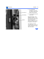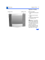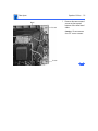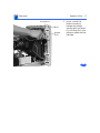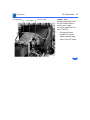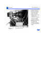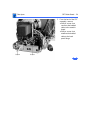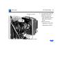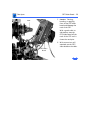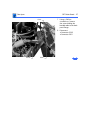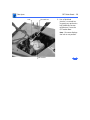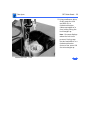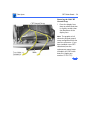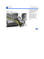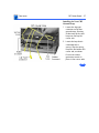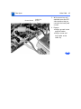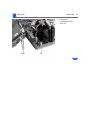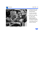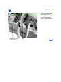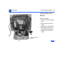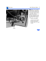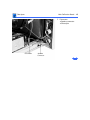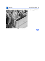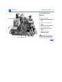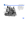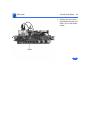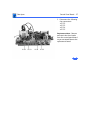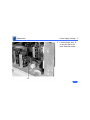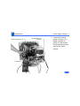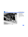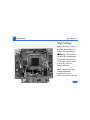
1
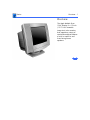
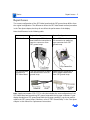
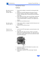
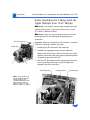
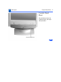
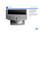
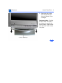
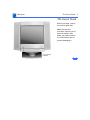
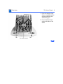
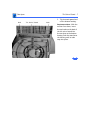
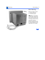
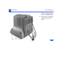
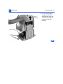
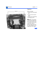
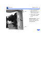
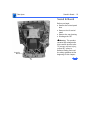
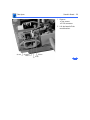
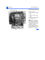
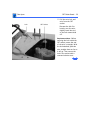
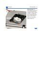
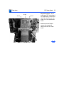
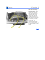
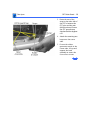
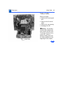
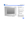
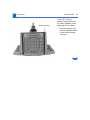
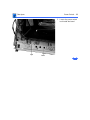
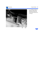
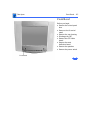
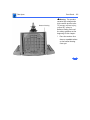
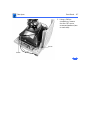
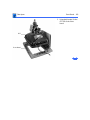
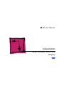
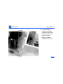
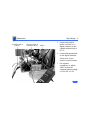
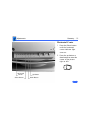
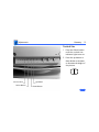
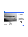
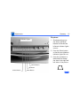
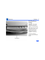
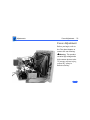
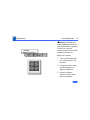
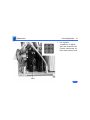
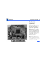
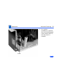
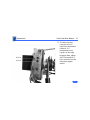
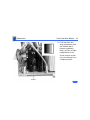
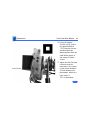
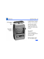
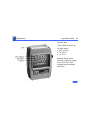
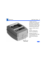
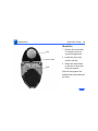
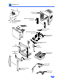
K Service Source
Apple Multiple Scan 15 AV
Display
K Service Source
Basics
Apple Multiple Scan 15AV
Display
Basics
Overview - 1
Overview
The Apple Multiple Scan
15AV Display is a 15-inch
(13.75-inch viewable
image size) color monitor
that supports a variety of
resolutions and that features
a built-in amplifier and
front-facing stereo
speakers.
Basics
Overview - 2
Monitor Features
Features of the Apple Multiple Scan 15AV Display include
the following:
• Antistatic, antiglare screen surface
• Multiple screen resolutions ranging from 640x480 to
1024x768
• Front-facing, CD-quality speakers
• Easy-access front headphone jack
• Support for Mac OS and Windows 95
• Compatible with Apple ColorSync software for the
closest possible color match between what is seen on the
monitor and what is printed or scanned
Basics
Repair Issues - 3
Repair Issues
The current configuration of the CRT/video board and the CRT ground strap differs from
the original configuration. The differences affect the CRT/video board removal procedure
in the Take Apart chapter, but they do not affect the performance of the display.
Note the differences in the following table:
Part
CRT/Video Board
Original Configuration
Two prongs on CRT/video
board shield for connection to
two-wire connector from
CRT ground strap
Newer Configuration
CRT Ground Strap
connection to
CRT/Video Board
Two-wire connector at end of
two twisted wires from CRT
ground strap
Spade lug-type connector at
end of single braided cable
from CRT ground strap
Clip on CRT/video board shield
for connection to spade lugtype connector from CRT
ground strap
Note: Apple part number 076-0757 is a kit that includes the new configuration of the
CRT/video board and a matching CRT ground strap with the lug-type connector. If your
display already has a CRT ground strap with the lug-type connector, you do not need to
replace the CRT ground strap. Otherwise, refer to “CRT Ground Strap” in the Take Apart
chapter in this manual for replacement instructions.
K Service Source
Specifications
Apple Multiple Scan 15AV
Display
Specifications
Characteristics - 1
Characteristics
Picture Tube
Phosphor
15-in. CRT (13.75-in. diagonal viewable image size)
Raster Size: 10.6 in. x 7.9 in. (270 mm x 200 mm)
Multiple scan
Antistatic, antiglare surface treatment
Dot Pitch: 0.28 mm
White Point: 9300° K
Shipping Brightness: 25 foot Lamberts (± 5 fL)
Aluminized P22 (red, green, blue)
Phosphor CIE Coordinates:
Red
x = 0.610 ± 0.020 y = 0.342 ± 0.020
Green x = 0.298 ± 0.020 y = 0.588 ± 0.020
Blue
x = 0.151 ± 0.015 y = 0.064 ± 0.015
Specifications
Characteristics - 2
Screen Resolution
Macintosh
PC-Compatibles
640x480 at 60 Hz in VGA mode
640x480 at 67 Hz in Macintosh mode
800x600 at 60 Hz in SVGA mode
800x600 at 72 Hz in SVGA mode
832x624 at 75 Hz in Macintosh mode
1024x768 at 60 Hz in Macintosh mode
1024x768 at 70 Hz in Macintosh mode
1024x768 at 75 Hz in Macintosh mode
640x480 at 60 Hz in VGA mode
800x600 at 60 Hz in SVGA mode
800x600 at 72 Hz in SVGA mode
1024x768 at 60 Hz in SVGA mode
1024x768 at 70 Hz in SVGA mode
1024x768 at 75 Hz in SVGA mode
Specifications
Characteristics - 3
Cable Connector
15-pin miniature D-type
Input Signals
Red, green, and blue signals; separate sync
Audio
Response: 50 Hz to 20,000 Hz
Output: 2 W
SPL: 82 db @ 1 kHz, 1 meter
Specifications
System
Requirements
Characteristics - 4
Power Macintosh, Macintosh Centris, Macintosh Quadra, some
Macintosh Performas, or any NuBus compatible Macintosh
with a Macintosh Display Card 24AC.
Macintosh II family, PowerBooks, Duo and Mini Dock, some
Macintosh Performa, Macintosh LC, LC II, LC III, and
Macintosh computers with Display Cards 4•8, 8•24, or
8•24GC installed work in 640x480 mode. Other modes
possible with additional adapters.
System software version 7.1 or later
Specifications
Monitor Timings
Characteristics - 5
640x480
Resolution @ 60 Hz
640x480
Resolution @ 67 Hz
Horizontal Timing
Back Porch: 48 dots
H SYNC: 96 dots
Front Porch: 16 dots
1 dot: 39.72 ns
1 H: 31.77 µs
1/dot: 25.175 MHz
Horizontal Timing
Back Porch: 96 dots
H SYNC: 64 dots
Front Porch: 64 dots
1 dot: 33.06878 ns
1 H: 28.5714 µs
1/dot: 30.24 MHz
Vertical Timing
Back Porch: 33 H
V SYNC: 2 H
Front Porch: 10 H
1/H: 31.5 kHz
1 V: 16.67 ms
Vertical Timing
Back Porch: 39 H
V SYNC: 3 H
Front Porch: 3 H
1/H: 35.0 kHz
1 V: 15.0 ms
Specifications
Monitor Timings
Characteristics - 6
800x600
Resolution @ 60 Hz
800x600
Resolution @ 72 Hz
Horizontal Timing
Back Porch: 88 dots
H SYNC: 128 dots
Front Porch: 40 dots
1 dot: 25.0 ns
1 H: 26.4 µs
1/dot: 40.0 MHz
Horizontal Timing
Back Porch: 64 dots
H SYNC: 120 dots
Front Porch: 56 dots
1 dot: 20.0 ns
1 H: 20.800 µs
1/dot: 50.0 MHz
Vertical Timing
Back Porch: 23 H
V SYNC: 4 H
Front Porch: 1 H
1 H: 37.879 µs
1/H: 16.58 kHz
1 V: 16.58 ms
Vertical Timing
Back Porch: 23 H
V SYNC: 6 H
Front Porch: 37 H
1/H: 48.077 kHz
1 V: 13.853 ms
Specifications
Monitor Timings
Characteristics - 7
832x624
Resolution @ 75 Hz
1024x768
Resolution @ 75 Hz
Horizontal Timing
1/H: 49.7 kHz
Back Porch: 224 dots
H SYNC: 64 dots
Front Porch: 32 dots
1 H: 20.1 µs
1/dot: 57.28 MHz
Horizontal Timing
Back Porch: 160 dots
H SYNC: 136 dots
Front Porch: 24 dots
1 dot: 15.385 ns
1 H: 20.677 µs
1/dot: 65.0 MHz
Vertical Timing
Back Porch: 38 H
V SYNC: 3 H
Front Porch: 2 H
1 V: 13.41 ms
Vertical Timing
Back Porch: 29 H
V SYNC: 6 H
Front Porch: 3 H
1/H: 48.363 kHz
1 V: 16.667 ms
Specifications
Controls and Ports - 8
Controls and Ports
User Controls
I/O Ports
Front Panel: power, select, up, down, recall, brightness,
contrast, sound volume
Additional picture controls available using the select button:
horizontal and vertical shift, horizontal and vertical size
Automatic degauss at power-on; manual degauss by turning power
switch off, then on (capable of full degauss after monitor is
turned off for 20 minutes or more)
Headphone/Speaker: one input port and one pass-through output
port
Specifications
Physical and Electrical - 9
Physical and Electrical
Power Supply
Input Frequency
Range
Size and Weight
Monitor Stand
Voltage: 100–240 VAC
Frequency: 50–60 Hz
Power: 75 W maximum; 8 W sleep mode
Horizontal: 30 kHz to 60.2 kHz
Vertical: 56 Hz to 75 Hz
Height: 14.93 in. (383 mm ± 5 mm)
Width: 17.3 in. (443 mm ± 5 mm)
Depth: 15.4 in. (395 mm ± 5 mm)
Weight: 31 lb. (14 kg)
Removable tilt-and-swivel stand
Specifications
Environmental - 10
Environmental
Temperature
Operating: 50°F to 104°F (10°C to 40°C)
Shipping: –4°F to +151°F (–40°C to +65°C)
Storage: 32°F to 140°F (0°C to 60°C)
Humidity
20% to 95% (noncondensing) over the range of 77°F to 104°F
(25°C to 40°C)
Altitude
Operating: 0 to 10,000 ft. (0 to 3,048 m)
Transit: 0 to 15,000 ft. (0 to 4,500 m)
Power Saving
Feature
Conforms to the Energy Star Program of the United States
Environmental Protection Agency
K Service Source
Troubleshooting
Apple Multiple Scan 15AV
Display
Troubleshooting
General - 1
General
The Symptom Charts included in this chapter will help you
diagnose specific symptoms related to your product. Because cures
are listed on the charts in the order of most likely solution, try
the first cure first. Verify whether or not the product continues to
exhibit the symptom. If the symptom persists, try the next cure.
( Note: If you have replaced a module, reinstall the original
module before you proceed to the next cure.)
For additional assistance, contact Apple Technical Support.
Troubleshooting
First Checklist/ - 2
First Checklist
Important: Many Apple Multiple Scan 15AV display modules
returned for repair are found to be fully operational. Read this
checklist before you return a module, and prevent needless module
replacement and unnecessary time delays.
The Apple Multiple Scan 15AV Display is not
compatible with all computers.
This display works with both Macintosh and IBM PC-compatible
computers. A video card may need to be installed to use this display
with some computers. For more information, see the computer
manual.
For more information on what computers or video cards are
compatible with the display, see the Specifications chapter.
The CRT raster will not always resemble a perfect
rectangle.
CRT tolerances allow for some distortion. Additional distortion can
be caused by magnetized metal objects (such as desks or file
cabinets). Move the unit to a different location if you notice raster
bowing or bent raster edges.
Jitter, faint lines, or screen movement can be caused
by external interference such as electronic devices
and fluorescent lights.
Fluorescent lights, other monitors, or electronic appliances
(such as coffee makers and copy machines) can cause raster
distortion. Move the unit to another room or building to help
determine if external interference is the source of the problem.
Note: If the raster has shifted up/down or right/left only, adjust
it using the user controls. However, keep in mind that, if you then
move the monitor, you may need to readjust the centering
controls.
If the display changes (for better or worse) when you move it to
another location, the environment is the source of the problem.
Relocate the monitor or move the distortion-causing object.
Troubleshooting
First Checklist - 3
A maladjusted screen can mimic the symptoms of
main deflection board or CRT failures.
By performing the adjustment procedures, you might determine if
one or more of the adjustments is the cause of the problem.
CRTs rarely fail.
Needless CRT replacement can be prevented by checking display
adjustments, checking the possibility of other defective modules,
and accepting small imperfections in screen display.
If you have any doubts about whether a CRT is defective, contact
Apple Technical Support.
Troubleshooting
Symptom Charts/No Raster - 4
Symptom Charts
No Raster
No raster (screen is
black); power
indicator light on
1
2
3
4
5
No raster; power
indicator light off
1
2
Ensure that the display is connected to a known-good video
source.
Adjust the front panel brightness and contrast controls.
Check the monitor’s video cable for breakage or damage.
Perform a continuity check to ensure that the video cable is
not at fault.
Slowly adjust the screen control on the flyback transformer
to see if the raster appears. If it reappears, perform the
“Cutoff and White Balance” procedure in the Adjustments
chapter.
Replace the main deflection board.
Ensure that the display is plugged in and that the power cord
is not damaged.
Replace the main deflection board.
Video
Display has one
predominant color
1
2
3
4
5
Verify that the CRT/video board is connected securely to the
CRT socket.
Inspect the video cable connector (at P301) on the CRT/
video board for breakage/continuity. This cable carries the
Red, Green, and Blue signals from the main deflection board
to the CRT/video board.
P301
Perform the “Cutoff and White Balance” procedure in the
Adjustments chapter.
Replace the CRT/video board.
If you suspect a defective CRT, contact Apple Technical
Support.
Troubleshooting
Symptom Charts/Video (Continued) - 5
Video (Continued)
Areas of the screen
have blotches of color
1
2
3
Screen is too bright;
adjusting Brightness
control does not
lower intensity
1
2
3
4
Since this type of problem (purity) is often caused by
magnetic fields in the area, place unit in another location to
see if symptom disappears, changes in its intensity, or
changes location on the screen.
Turn off the monitor power switch, wait five minutes, then
turn it back on. This enables the monitor’s internal
degaussing coil.
Severe magnetic field problems require the use of an
external degaussing coil. (Degaussing coils can be purchased
at most larger electronic parts stores.)
Perform the “Cutoff and White Balance” procedure in the
Adjustments chapter.
Replace the CRT/video board.
Replace the main deflection board.
If you suspect a defective CRT, contact Apple Technical
Support.
Troubleshooting
Symptom Charts/Geometry - 6
Geometry
Raster not centered
1
2
Adjust either or both horizontal center and vertical center
controls. See “Geometry” in the Adjustments chapter.
Adjust the horizontal center switch (SW701 on version G
only). See “Horizontal Centering” in the Adjustments
chapter.
Size of the horizontal
and/or vertical
raster is incorrect
Use the appropriate size controls to set the vertical height to 200
mm (7.9 inches) and the horizontal width to 270 mm (10.6
inches). Refer to “Geometry” in the Adjustments chapter.
One or both sides of
the raster is bowed
1
2
3
Raster is narrower or
wider at the top of the
screen than at the
bottom
1
2
3
To minimize the bowing, perform the “Pincushion”
procedure in the Geometry section of the Adjustments
chapter. Keep in mind that there is some allowed tolerance
and the setting will NOT always be perfect.
Important: As mentioned in step one, some degree of bowing
is still considered to be within tolerance. If you have any
doubts, contact Apple Technical Support before replacing a
board that may not fix the problem.
Replace the main deflection board.
To set the keystone control for optimum screen performance,
perform the “Keystone” procedure in the Geometry section
of the Adjustments chapter. Keep in mind that there is some
allowed tolerance and the setting will NOT always be perfect.
Important: As mentioned in step one, some trapezoidal
imperfection is still considered to be within tolerance. If you
have any doubts, contact Apple Technical Support before
replacing a board that may not fix the problem.
Replace the main deflection board.
Troubleshooting
Symptom Charts/Sound Problems - 7
Sound Problems
Distorted or no sound
coming through one
speaker
Disconnect the wires to both speakers. Using jumper cables,
connect the right speaker wire to the left speaker and the left
speaker wire to the right speaker. This will isolate the problem to
a defective speaker or a defective main deflection board.
Distorted or no sound
in both speakers
1
On a Performa 6400,
sound comes through
Performa subwoofer
even though
headphones are
plugged into
headphone jack on
front of display
To mute the subwoofer, do any one of the following:
• Keep headphones plugged into headphone jack on front of
display, but mute subwoofer using Sound and Displays
Control Panel.
• Keep headphones plugged into headphone jack on front of
display, but lower volume of subwoofer by turning balance
control knob at rear of Performa 6400 fully
counterclockwise.
• Plug headphones into headphone jack on front of Performa
6400.
• Plug headphones into headphone jack at rear of Performa
6400.
2
Try another sound source to ensure that you are not using a
defective CD or other sound device.
Replace the main deflection board.
K Service Source
Take Apart
Apple Multiple Scan 15AV
Display
Take Apart
Safety Guidelines for Taking Apart the Apple Multiple Scan 15AV
Safety Guidelines for Taking Apart the
Apple Multiple Scan 15AV Display
±Warning: This product contains high voltage and a highvacuum picture tube. To prevent serious injury, review
CRT safety in Bulletins/Safety.
Never use a grounding wriststrap until after
discharging the CRT and setting up an ongoing ground
connection.
±Warning:
CRT Discharge Tool
Anode Cap
Important: Whenever the housing of the monitor is removed
and before replacing a module, you must
1
Discharge the CRT and remove the anode cap.
3
With the CRT discharged and the ongoing ground in place,
wear a grounding wriststrap to prevent equipment
damage from static electricity.
2
Establish an ongoing ground by using a cable with
alligator clips at both ends. Connect one end to the anode
aperture, and connect the other end to the braided ground
strap that wraps around the CRT.
Anode Aperture
Note: The ground strap
and CRT/video board on
newer displays are
somewhat different than
pictured here. Refer to
“Repair Issues” in the
Basics chapter for details.
Ongoing Ground
Ground Strap
Take Apart
Control Panel Door - 2
Control Panel
Door
No preliminary steps are
required before you begin
this procedure.
Control Panel Door
Take Apart
Control Panel Door - 3
1
2
Position the monitor
close to the edge of a
table and so that the
screen faces you.
Press down on the center
of the door so it flips
open.
Take Apart
Control Panel Door - 4
3
Grasp each side of the
door and pull the door
down to release it from
its hinges.
Replacement Note: Position
the door under the bezel so
the hinges line up with the
bezel contacts. Push the door
onto the bezel until it snaps
into place.
Control Panel Door
Take Apart
Tilt-Swivel Stand - 5
Tilt-Swivel Stand
Before you begin, remove
the control panel door.
Note: Because this
procedure requires you to
place the monitor face
down, you need to remove
the control panel door to
prevent damaging it.
Tilt-Swivel
Stand
Take Apart
Tilt-Swivel Stand - 6
1
2
Tab
Tilt-Swivel Stand
Tab
Place the monitor facedown on a padded surface
with the bottom of the
stand facing you.
Press inward on both
tabs on the sides of the
stand.
Take Apart
Tilt-Swivel Stand - 7
3
Hook
Tilt-Swivel Stand
Hook
Tilt the stand upward and
off the bottom housing.
Replacement Note: With the
monitor face down, insert
the two hooks on the back of
the tilt-swivel stand into
the two slots on the bottom
housing. Push the stand onto
the housing until its tabs
snap into place.
Take Apart
Rear Housing - 8
Rear
Housing
Rear Housing
Before you begin, remove
• Control panel door
• Tilt-swivel stand
This product
contains high voltage and a
high-vacuum picture tube.
To prevent serious injury,
review CRT safety in
Bulletins/Safety and read
the safety guidelines at the
beginning of this chapter.
±Warning:
Take Apart
Rear Housing - 9
1
2
Screws
Place the monitor facedown on a padded surface.
Remove the four Phillips
screws (two on each
side).
Take Apart
Rear Housing - 10
3
Rear
Housing
Video Cable
Lift the rear housing
straight off the CRT
assembly and route the
video cable through the
opening in the rear
housing.
Take Apart
Speaker - 11
Speaker
Speakers
Before you begin,
• Remove the control panel
door
• Remove the tilt-swivel
stand
• Remove the rear housing
• Discharge the CRT
This product
contains high voltage and a
high-vacuum picture tube.
To prevent serious injury,
review CRT safety in
Bulletins/Safety and read
the safety guidelines at the
beginning of this chapter.
±Warning:
Take Apart
Speaker - 12
1
Speaker Connectors
Locate the inoperative
speaker and disconnect
the speaker connector
near the display’s
bottom corner, either
• Red speaker connector
on the right
• White speaker
connector on the left
Take Apart
Speaker - 13
2
Routing
Channel
Speaker Wire
Remove the speaker wire
from its routing channel.
Take Apart
Speaker - 14
3
Screwdriver
Foam Gasket
Speaker
4
Use a flat-blade
screwdriver to pry off
the speaker and its foam
gasket from the bezel.
Lift the speaker from the
inside bezel.
Replacement Note: When
replacing a speaker, verify
that the bezel is clean, peel
off the foam gasket’s
adhesive backing, and apply
the speaker to the bezel.
The speakers are fully
interchangeable, so you can
replace a speaker on either
side of the bezel.
Take Apart
Speaker Grilles - 15
Speaker Grilles
Speaker Grille
Speaker Grille
Before you begin,
• Remove the control panel
door
• Remove the tilt-swivel
stand
• Remove the rear housing
• Discharge the CRT
This product
contains high voltage and a
high-vacuum picture tube.
To prevent serious injury,
review CRT safety in
Bulletins/Safety and read
the safety guidelines at the
beginning of this chapter.
±Warning:
Take Apart
Speaker Grilles - 16
1
Bezel
Screw
Screw
Remove the two recessed
screws at the top and
bottom of the inner bezel
sides.
Caution: Do not remove
the CRT corner screws.
Take Apart
Speaker Grilles - 17
2
Screwdriver
Bezel
Speaker
Grille
Insert a small flatblade screwdriver
between the outside
speaker grille and bezel.
Pry off the grille in four
places to release the four
side tabs.
Take Apart
Speaker Grilles - 18
3
Hook
4
Gently tilt the speaker
grille toward the
display face to release it
from the bezel hooks.
Repeat steps 1 through 3
for the other speaker
grille.
Replacement Note: The left
and right speaker grilles
come as a pair and are not
interchangeable.
Hook
Take Apart
Sound In Board - 19
Sound In Board
Before you begin,
• Remove the control panel
door
• Remove the tilt-swivel
stand
• Remove the rear housing
• Discharge the CRT
This product
contains high voltage and a
high-vacuum picture tube.
To prevent serious injury,
review CRT safety in
Bulletins/Safety and read
the safety guidelines at the
beginning of this chapter.
±Warning:
Sound In
Board
Take Apart
Sound In Board - 20
1
2
Screw
Sound In
Board
Screw
P156
Remove
• Two screws
• P156 connector
Lift the board off the
metal bracket.
Take Apart
CRT/Video Board
CRT/Video Board - 21
CRT/Video Board
Before you begin,
• Remove the control panel
door
• Remove the tilt-swivel
stand
• Remove the rear housing
• Discharge the CRT
This product
contains high voltage and a
high-vacuum picture tube.
To prevent serious injury,
review CRT safety in
Bulletins/Safety and read
the safety guidelines at the
beginning of this chapter.
±Warning:
Take Apart
Ground Cable
CRT/Video Board - 22
CRT Shield
Ground Cable
Caution: When
disconnecting cables from
the CRT/video board, be
careful not to apply
excessive pressure on the
neck of the CRT.
1
Disconnect the two
braided CRT ground
cables located on both
sides of the CRT shield.
Take Apart
CRT/Video Board - 23
2
Two-Wire
Connector
Braided Cable at E2
From the side of the CRT
assembly, disconnect
• Two-wire connector
behind CRT/video
board (On newer
displays the two-wire
connector was
replaced by a braided
cable with a spade
lug-type connector.)
• Braided cable at E2 to
the right of the
flyback transformer
on the main deflection
board
Take Apart
CRT/Video Board - 24
3
Screw
Screw
From the back of the CRT
assembly, remove
• Phillips screw that
connects the braided
cable to the sound in
board
• Phillips screw that
attaches the braided
cable to the back
panel flange
Take Apart
CRT/Video Board - 25
Red Wire at P304
Two-Wire Connector at P305
4
From the side of the CRT
assembly, disconnect
• Red wire with the
gray connector on the
CRT/video board at
P304
• Black two-wire
connector on the CRT/
video board at P305
Take Apart
CRT/Video Board - 26
5
Neck
6
CRT/Video
Board
Caution: Twisting,
bending, or applying
force to the CRT/video
board could damage the
neck of the CRT.
With a gentle side-toside motion, ease the
CRT/video board off the
neck of the CRT until it
clears the neck pins.
With some wires still
attached, set the CRT/
video board on the table.
Take Apart
CRT/Video Board - 27
P301
7
8
Screw
P302
Using a Phillips
screwdriver, remove
the screw holding the
braided cable to the back
panel flange.
Disconnect
• Connector P302
• Connector P301
Take Apart
CRT/Video Board - 28
Lock
Screwdriver
9
Use a flat-blade
jeweler’s screwdriver
to gently pry up the wire
lock (about one to two
millimeters) from the
CRT socket base.
Note: On newer displays
the lock is not present.
CRT Socket
Take Apart
CRT/Video Board - 29
10 Using needlenose pliers,
firmly grasp the lock
and twist it in a
clockwise direction
(about one-eighth of a
turn) while pulling the
lock straight up.
Note: On newer displays
where the lock is not
present, firmly grasp
the wire and twist it in a
clockwise direction
three to four turns. Pull
the wire straight up.
Needlenose Pliers
Lock
Take Apart
CRT/Video Board - 30
Lock
CRT Socket
11 Pull the wire lock and
wire from the CRT
socket.
Because the lock fits
loosely over the wire,
slightly bend the wire
so the lock cannot slide
off.
Replacement Note: Before
securing the lock inside the
CRT socket, ensure the end
of the wire is straight. With
the lock attached, push the
wire straight down as far as
it will go. Then secure the
lock in the socket with a
counterclockwise turn.
Take Apart
CRT/Video Board - 31
Replacement Note: On
newer displays the wire lock
is not present and the wire
receptacle on the CRT socket
is smaller. To replace the
wire, ensure the end of the
wire is straight and push it
down as far as it will go.
Gently tug on the wire to
ensure a secure fit.
Take Apart
Screw
CRT/Video Board - 32
Shield
Screw
Replacement Note: Before
returning a CRT/video board
for replacement, remove and
retain the shield so you can
attach it to the replacement
board.
Remove the two Phillips
screws that secure the
shield onto the CRT/video
board.
Take Apart
CRT/Video Board - 33
CRT Ground Strap
Replacement Note: When
replacing the CRT/video
board, you might need to
replace the CRT ground
strap as well. Check the
ground connection on the
CRT/video board shield and
the connector on the CRT
ground strap. The
connections must match.
Refer to “Repair Issues” in
the Basics chapter for more
details.
Take Apart
CRT/Video Board - 34
Removing the Old CRT
Ground Strap
1
Place the display facedown on a thick book that
is slightly smaller than
the dimensions of the
display face.
Note: The graphic at left
shows the original ground
strap configuration with the
two-wire connector. If you
have installed a new CRT/
video board, use the
replacement ground strap
included in the CRT/video
board kit (Apple part
number 076-0757).
Take Apart
CRT/Video Board - 35
2
3
Cut the four plastic cable
ties that secure the CRT
ground strap to the
degauss coil.
Remove the four CRT
corner screws and
washers; ensure the
rubber grommets
remain in the corner
tabs.
Take Apart
CRT/Video Board - 36
4
5
Starting at the top
corner of the CRT, lift
off the end loop of the
ground strap from the
corner tab. Repeat for
the other three loops.
Remove the old CRT
ground strap from the
display assembly.
Take Apart
CRT/Video Board - 37
Installing the New CRT
Ground Strap
1
2
Locate the lug-type
connector on the new
ground strap. Starting
at that end, slip the end
loop over the top left
corner tab.
Locate the loop that is
connected with a
spring. Slip the spring
loop over the bottom left
corner tab, as shown.
Ensure the rubber
grommets remain in
place in the corner tabs.
Take Apart
CRT/Video Board - 38
3
4
5
Route the rest of the
strap to the other side of
the CRT in between the
CRT yoke and the main
deflection board. Ensure
the CRT ground strap
slips beneath the degauss
coil.
Attach the remaining two
loops over the corner
tabs.
Ensure the rubber
grommets remain in the
corner tabs. Lift up and
support the bezel
assembly to secure the
four corner screws.
Take Apart
CRT/Video Board - 39
6
7
Ensure the CRT ground
strap maintains contact
with the CRT on all three
sides and the degauss coil
is centered on the CRT.
Adjust as necessary.
Using the plastic cable
ties included with the
ground strap in the CRT/
video board kit, secure
the ground strap to the
degauss coil at the two
top corners. Use the
remaining two cable ties
to secure the ground
strap to the middle of the
degauss coil.
Take Apart
Video Cable - 40
Video Cable
Before you begin,
• Remove the control panel
door
• Remove the tilt-swivel
stand
• Remove the rear housing
• Discharge the CRT
This product
contains high voltage and a
high-vacuum picture tube.
To prevent serious injury,
review CRT safety in
Bulletins/Safety and read
the safety guidelines at the
beginning of this chapter.
±Warning:
Video Cable
Take Apart
Video Cable - 41
Ground Cable
Ground Cable
Caution: Twisting, bending,
or applying force to the
CRT/video board could
damage the neck of the CRT.
1
2
Two-Wire
Connector
CRT/Video Board
Two-Wire
Connector
Disconnect
• Two braided CRT
ground cables from
the CRT shield
• Two two-wire
connectors from the
CRT/video board
With a gentle side-toside motion, ease the
CRT/video board off the
neck of the CRT until it
clears the neck pins.
Take Apart
Video Cable - 42
Ground Screw
Cable Clip
Screw
3
4
With some wires still
attached, move the CRT/
video board so that you
can reach the back panel
screws.
Remove
• Phillips ground screw
and lock washer
• Phillips screw and
lock washer at the
cable clip
Take Apart
Video Cable - 43
5
P301
E3
Disconnect
• Connector P301
• Pin E3
Take Apart
Video Cable - 44
6
7
8
Disconnect P401 from
the center of the main
deflection board.
Cut the tie wrap that
holds the P401 cable.
Remove the cable from
the cable clamp.
Replacement Note:
Secure the P401 cable
by routing it through the
cable clamp and using a
new wire tie wrap.
Cable Clamp
Tie Wrap
P401
Take Apart
Video Cable - 45
9
Video Cable Hook
Strain Relief
Hook
At the video cable strain
relief, press the two
hooks forward and pull
up on the video cable
strain relief to release it
from the slot.
Take Apart
Main Deflection Board - 46
Main Deflection
Board
Before you begin,
• Remove the control panel
door
• Remove the tilt-swivel
stand
• Remove the rear housing
• Discharge the CRT and
disconnect the anode cap
• Remove the CRT/video
board
Main Deflection
Board
Take Apart
Main Deflection Board - 47
This product
contains high voltage and a
high-vacuum picture tube.
To prevent serious injury,
review CRT safety in
Bulletins/Safety and read
the safety guidelines at the
beginning of this chapter.
±Warning:
1
Screw
Remove the Phillips
screw from the chassis
bracket (next to the
bottom right CRT corner
screw).
Take Apart
Main Deflection Board - 48
2
Ground Pin
Speaker
Connector
Disconnect
• Speaker connector
• Ground pin
Take Apart
Main Deflection Board - 49
3
P701
Disconnect the CRT yoke
wire at P701.
Take Apart
Main Deflection Board - 50
4
Speaker
Connector
P902
Disconnect
• Speaker connector
• Degaussing coil at
P902
Take Apart
Main Deflection Board - 51
5
6
Bottom
Housing
Screw
Screw
Place the monitor facedown on a padded surface.
Remove the two Phillips
screws from the bottom
housing.
Take Apart
Main Deflection Board - 52
7
Chassis
8
Screwdriver
Tab
Tab
While grasping the end
of the main deflection
board chassis with one
hand, use a flat-blade
screwdriver to press in
on one of the two tabs on
the bottom of the bezel
assembly.
Press in on the other
tab, and slide the main
deflection board straight
up and off of the CRT
assembly.
Refer to this chapter to
remove the sound in
board, video cable, and
control panel board that
Take Apart
Main Deflection Board - 53
are attached to the main
deflection board chassis.
Replacement Note: With the
control panel board secured
to the replacement main
deflection board, align the
side edges of the main
deflection board with the two
slide rails on the bottom
housing.
Slide Rails
Bottom Housing
Slide Rails
Ensure no cables get
pinched as you slide the
board into place. With the
board in place, be sure to
reconnect all cables
including the anode cap.
Take Apart
Control Panel Board - 54
Control Panel
Board
Before you begin,
• Remove the control panel
door
• Remove the tilt-swivel
stand
• Remove the rear housing
• Discharge the CRT
• Remove the CRT/video
board
• Remove the main
deflection board
This product
contains high voltage and a
high-vacuum picture tube.
±Warning:
Control Panel Board
Take Apart
Control Panel Board - 55
To prevent serious injury,
review CRT safety in
Bulletins/Safety and read
the safety guidelines at the
beginning of this chapter.
1
Screw
Remove the Phillips
screw.
Take Apart
Control Panel Board - 56
2
Holder
Slightly tilt the control
panel board forward, and
slide it out of the plastic
holder.
Take Apart
Control Panel Board - 57
3
Disconnect the following
four connectors:
• P152
• P153
• P154
• P155
Replacement Note: Remove
and retain the three knobs
from the control panel board
so you can attach them to the
replacement board.
P152
P153
P154
P155
Take Apart
Power Switch - 58
Power Switch
Before you begin,
• Remove the control panel
door
• Remove the tilt-swivel
stand
• Remove the rear housing
• Discharge the CRT
• Remove the CRT/video
board
• Remove the main
deflection board
This product
contains high voltage and a
high-vacuum picture tube.
To prevent serious injury,
±Warning:
Power Switch
Take Apart
Power Switch - 59
Bottom Housing
review CRT safety in
Bulletins/Safety and read
the safety guidelines at the
beginning of this chapter.
1
Place the monitor face
down on a padded surface
so the bottom housing
faces you.
Take Apart
Power Switch - 60
2
Lock
Bezel
Locate the power switch
lock inside the bezel.
Take Apart
Power Switch - 61
3
Tab
Lock
Use needlenose pliers to
grasp the lower tab of
the power switch lock.
Pull up the lock as far as
it will go.
Take Apart
Power Switch - 62
4
Slot
Side
Tab
Needlenose Pliers
Tab
Needlenose Pliers
While holding the lock
tab up, use a second pair
of needlenose pliers to
pinch the two side tabs
so that they fit through
the slot in the lock.
Repeat for the other side
tabs.
Take Apart
Power Switch - 63
5
Power
Switch
Spring
Lock
Pull the lock off of the
power switch and spring.
Take Apart
Power Switch - 64
6
Tilt up the CRT assembly
to pull out the power
switch and spring from
the front side of the
bezel.
The power switch
assembly consists of the
three pieces shown here.
Lock
Spring
Power
Switch
Take Apart
Front Bezel - 65
Front Bezel
Before you begin,
• Remove the control panel
door
• Remove the tilt-swivel
stand
• Remove the rear housing
• Discharge the CRT
• Remove the CRT/video
board
• Remove the main
deflection board
• Remove the speakers
• Remove the power switch
Front Bezel
Take Apart
Front Bezel - 66
This product
contains high voltage and a
high-vacuum picture tube.
To prevent serious injury,
review CRT safety in
Bulletins/Safety and read
the safety guidelines at the
beginning of this chapter.
±Warning:
Bottom Housing
1
Place the monitor face
down on a padded surface
so the bottom housing
faces you.
Take Apart
Front Bezel - 67
2
Screw
Screw
Using a Phillips
screwdriver, remove
the four CRT corner
screws and washers (two
on each side).
Take Apart
Front Bezel - 68
3
CRT
Front Bezel
Using both hands, lift the
CRT off of the front
bezel.
K Service Source
Adjustments
Apple Multiple Scan 15AV
Display
Adjustments
Power Supply Voltage - 1
Power Supply
Voltage
Before you begin, refer to
the Take Apart chapter to
remove the rear housing.
Warning: This product
contains high voltage and a
high-vacuum picture tube.
To prevent serious injury,
review CRT safety in
Bulletins/Safety.
±
Note: Perform the power
supply voltage adjustment
whenever the main
deflection board is replaced.
Adjustments
Power Supply Voltage - 2
1
2
3
Turn on the display and
let it warm up for five
minutes.
Using the control strip,
set the screen
resolution to 640x480.
Using the Display
Service Utility, select
the crosshatch display
pattern with the black
background from the
Standard Patterns
screen.
Adjustments
Power Supply Voltage - 3
4
J5
Locate jumper wire J5
on the left side of the
main deflection board.
Adjustments
Positive Probe at J5
Voltmeter
Power Supply Voltage - 4
Ground Probe at
Chassis
5
Connect the positive
probe (red wire) of a
digital voltmeter to
jumper J5 and connect
the ground probe (black
wire) to the metal
chassis.
Adjustments
Power Supply Voltage - 5
6
Positive Probe at J5
VR951
While maintaining the
voltmeter probe
connections, use a
plastic screwdriver to
adjust VR951 until the
voltmeter reads 50 VDC
± 0.2V.
Adjustments
High Voltage - 6
High Voltage
Before you begin, refer to
the Take Apart chapter to
remove the rear housing.
Warning: This product
contains high voltage and a
high-vacuum picture tube.
To prevent serious injury,
review CRT safety in
Bulletins/Safety.
±
Note: Perform the highvoltage adjustment
whenever the main
deflection board is replaced.
Adjustments
High Voltage - 7
1
2
3
Turn on the display and
let it warm up for five
minutes.
Using the control strip,
set the screen
resolution to 640x480.
Using the Display
Service Utility, select
the crosshatch display
pattern with the black
background.
Adjustments
High Voltage - 8
Cathode
4
Locate diode D713
between the flyback
transformer and large
heatsink on the main
deflection board.
Notice the cathode
(striped end) of D713.
D713
Adjustments
Ground Probe at
Chassis
High Voltage - 9
Positive Probe at
Cathode of D713
5
VR501
6
7
Connect the positive
probe (red wire) of a
digital voltmeter to the
cathode (striped end) of
D713.
Connect the ground probe
of the digital voltmeter
(black wire) to the
monitor’s metal chassis.
Use a plastic
screwdriver to adjust
VR501 so that the
voltmeter reads a voltage
of 42.5 VDC ± 0.2V.
Adjustments
Geometry - 10
Geometry
Before you begin, open the
control panel door.
Note: In most cases, the
preset factory settings
require no adjustments to
the picture. However, you
can fine-tune the screen
display by using the front
panel controls.
Control Panel Door
Adjustments
Geometry - 11
Vertical Center
1
2
Vertical
Center
Select Button
Up Button
Down Button
Press the Select button
until the vertical center
indicator light turns on.
Press the up button or
down button to move the
center of the picture up
or down.
Adjustments
Geometry - 12
Horizontal Center
1
2
Horizontal
Center
Select Button
Up Button
Down Button
Press the Select button
until the horizontal
center indicator light
turns on.
Press the up button or
down button to move the
center of the picture
right or left.
Adjustments
Geometry - 13
Vertical Size
1
2
Vertical Size
Select Button
Up Button
Down Button
Press the Select button
until the vertical size
indicator light turns on.
Press the up button or
down button to increase
or decrease the height of
the picture.
Adjustments
Geometry - 14
Horizontal Size
1
2
Horizontal Size
Select Button
Up Button
Down Button
Press the Select button
until the horizontal size
indicator light turns on.
Press the up button or
down button to increase
or decrease the width of
the picture.
Adjustments
Geometry - 15
Pincushion
Indicator Lights
1
2
Recall Button
Select Button
Up Button
Down Button
Simultaneously press
the Select and Recall
buttons so that the two
leftmost indicator lights
turn on.
Press the up button or
down button to change
the curvature of the
right and left sides of the
picture.
Adjustments
Geometry - 16
Keystone
Indicator Lights
1
2
3
Recall Button
Up Button
Select Button
Down Button
Simultaneously press
the Select and Recall
buttons so that the two
leftmost indicator lights
turn on.
Press the Select button
so that the two rightmost
indicator lights turn on.
Press the up button or
down button to change
the slant of the right and
left sides of the picture.
Adjustments
Geometry - 17
Recalling Factory
Settings
Important: The monitor
controls are set at the
factory. To fine-tune and
adjust the picture, use the
front panel controls. The
monitor will use your
settings each time the
computer is turned on.
To revert to factory
settings, press the Recall
button.
Recall Button
Adjustments
Focus Adjustment - 18
Focus Adjustment
Before you begin, refer to
the Take Apart chapter to
remove the rear housing.
Warning: This product
contains high voltage and a
high-vacuum picture tube.
To prevent serious injury,
review CRT safety in
Bulletins/Safety.
±
Adjustments
Focus Adjustment - 19
Because you
make adjustments from the
rear of the monitor, position
a mirror to view the
monitor screen. Do not reach
around the monitor to
adjust the controls.
±Warning:
1
2
3
Turn on the display and
let it warm up for five
minutes.
Using the control strip,
set the display to its
highest resolution.
Using the Display
Service Utility, select
the focus pattern.
Adjustments
Focus Adjustment - 20
4
Contrast
Brightness
Set the brightness and
contrast controls to
maximum (turn fully
clockwise).
Adjustments
Focus Adjustment - 21
5
Focus
Use a plastic
screwdriver to adjust
the Focus control on the
flyback transformer for
best center screen focus.
Adjustments
Focus Adjustment - 22
6
Brightness
Reset the brightness
control to its detent
(middle) position.
Adjustments
Horizontal Centering - 23
Horizontal
Centering
Before you begin, refer to
the Take Apart chapter to
remove the rear housing.
Warning: This product
contains high voltage and a
high-vacuum picture tube.
To prevent serious injury,
review CRT safety in
Bulletins/Safety.
±
Because you
make adjustments from the
rear of the monitor, position
a mirror to view the
±Warning:
Adjustments
Horizontal Centering - 24
monitor screen. Do not reach
around the monitor to
adjust the controls.
Note: Perform the
horizontal centering
adjustment whenever the
horizontal center control on
the front panel does not have
sufficient range.
1
Using the control strip,
set the monitor to its
highest resolution.
Adjustments
Horizontal Centering - 25
2
Contrast
Brightness
Set both brightness and
contrast controls to
maximum (turn fully
clockwise).
Adjustments
Horizontal Centering - 26
3
SW701
Use a plastic
screwdriver to position
the arm of the horizontal
center switch (SW701)
until the raster is
centered.
Adjustments
Horizontal Centering - 27
4
Brightness
Reset the brightness
control to its detent
(middle) position.
Adjustments
Cutoff and White Balance - 28
Cutoff and White
Balance
Before you begin, refer to
the Take Apart chapter to
remove the rear housing.
Warning: This product
contains high voltage and a
high-vacuum picture tube.
To prevent serious injury,
review CRT safety in
Bulletins/Safety.
±
Because you
make adjustments from the
rear of the monitor, position
a mirror to view the
±Warning:
Adjustments
Cutoff and White Balance - 29
monitor screen. Do not reach
around the monitor to
adjust the controls.
Caution: When adjusting the
controls on the CRT/video
board, be careful not to
apply excessive pressure to
the neck of the CRT.
Note: Perform cutoff and
white balance adjustments
whenever the CRT/video
board has been replaced or
the screen exhibits a
predominant color tint.
Adjustments
Cutoff and White Balance - 30
1
2
3
Turn on the display and
let it warm up for at
least 10 minutes.
Using the control strip,
set the display to its
highest screen
resolution.
Using the Display
Service Utility, select
the all-black display
pattern.
Adjustments
Cutoff and White Balance - 31
4
Contrast
Brightness
Preset both brightness
and contrast controls to
maximum (turn fully
clockwise).
Adjustments
Cutoff and White Balance - 32
5
Sub-Bright
VR306
Use a plastic
screwdriver to preset
the Sub-Brightness
control (VR306) to its
maximum setting
(counterclockwise).
Adjustments
Cutoff and White Balance - 33
6
R Drive
VR301
G Drive
VR302
Sub-Contrast
VR303
7
Preset the following
controls to their center
positions.
• Sub-Contrast control
(VR303)
• R Drive control
(VR301)
• G Drive control
(VR302)
If you have set the
controls correctly and
the monitor is operating
normally, the raster
should have a bluish
cast. If not, recheck the
controls you preset in
steps 4, 5, and 6.
Adjustments
Cutoff and White Balance - 34
8
9
Screen
Using the Display
Service Utility, select
the gray bars display
pattern.
With the room lights
dimmed, use a plastic
screwdriver to slowly
adjust the Screen control
so that the leftmost bar
is completely black.
Adjustments
Cutoff and White Balance - 35
10 Use a plastic
screwdriver to adjust
the G Bias (VR305)
cutoff control until the
screen has a bluishgreen hue in the darkest
bars.
R Bias
(VR304)
G Bias
(VR305)
11 Adjust the R Bias
(VR304) cutoff control
to produce neutral gray
in the darkest bars.
Note: If you still see a
predominant color in
the darkest bars,
continue adjusting the
two bias controls as
follows until the bars
Adjustments
Cutoff and White Balance - 36
become neutral gray:
• If the display looks
too red, turn up the G
Bias or turn down the
R Bias
• If the display looks
too green, turn up
the R Bias or turn
down the G Bias
12 Set the brightness
control to its detent
(middle) position.
Brightness
Adjustments
R Drive
G Drive
Cutoff and White Balance - 37
13 The drive controls
normally will not
require an adjustment.
However, if a
predominant color
remains in the eight
brightest bars, adjust
the R Drive and/or G
Drive controls to make
these bars appear
whiter.
Adjustments
Cutoff and White Balance - 38
14 If required, perform a
slight readjustment of
the G Bias and R Bias
cutoff controls to
maintain neutral gray
in the eight darkest bars.
R Bias
G Bias
Adjustments
Cutoff and White Balance - 39
15 If the previous two
steps caused more than
the leftmost bar to
become completely
black, perform a slight
readjustment of the
Screen control so that
only the leftmost bar is
completely black.
Screen
Adjustments
Cutoff and White Balance - 40
16 Using the Display
Service Utility, select
the Apple MultiScan
1705 selection screen,
and then select the
display pattern with the
small white square in
the center of a black
screen.
Sub-Contrast
17 Adjust the Sub-Contrast
control so that the
luminance in the center
of the screen measures
25 foot lamberts on a
photometer, which on a
light meter is
• 21 on the bottom
Adjustments
Cutoff and White Balance - 41
scale of the R77 light
meter
• 21 on the red scale of
the 246 light meter
See the next section, “Light
Meter Setup,” for
instructions on how to use
the light meters.
Adjustments
Light Meter Setup - 42
Light Meter Setup
This topic covers setup for
two light meter models:
R77 and 246. Model R77
(Apple part number 0760310) is the newest model
available.
Model R77
The R77 light meter is
capable of reading luminance
from 10 to 1,000
footcandles (fc).
Before you begin, remove
the 10X multiplier plate
Adjustments
Light Meter Setup - 43
from the lens.
Three scales are shown on
the light meter:
• 200-1000 fc
• 50-250 fc
• 10-50 fc
Because display screen
luminance typically ranges
from 10 to 50 fc, take
readings from the bottom
scale only.
Adjustments
Light Meter Setup - 44
To measure a display
screen’s luminance,
1
2
Set the scale switch to
the bottom position (to
set up the 10-50 fc
scale).
Place the lens against the
middle of the screen and
read the bottom scale.
Note: When the light meter
is not in use, slide the scale
switch to its top position,
and store the meter in its
protective case.
Important: If you suspect the
light meter is giving false
Adjustments
Light Meter Setup - 45
readings, verify the
readings with a known-good
light meter or photometer.
Also check the age of the R77
light meter by its four-digit
manufacturing date stamp
(such as 0398 for March
1998).
Caution: Dropping the
meter can permanently
damage its accuracy. A
shock-damaged meter might
read incorrectly or its
pointer may not drop to
zero.
Adjustments
Light Meter Setup - 46
Model 246
Lens
Swivel Head
1
2
3
Scale
Remove the metal slide,
if installed, from the
top of the light meter.
Install the white lens
with the red dot.
Rotate the swivel head
so the lens of the meter
faces the monitor.
Place the lens against the
middle of the screen and read
the scale.
K Service Source
Exploded View
Apple Multiple Scan 15AV
Display
Exploded View
1
Rear Housing
922-2244
CRT/Video Board Kit
with Ground Strap
076-0757
Speaker Grille Gaskets
922-2240
Sound-Out Cable
922-1781
Main Deflection Board
661-1143
Sound In Board
922-2238
Control Panel Board
922-2237
Bezel
922-2432
Speaker
922-2245
Control Panel
Door
922-2243
Monitor Stand
922-2242
Power Button
922-2433
Video Cable
922-2241
Speaker Cover Set
922-2239
Power Cord
590-0380