1
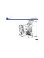
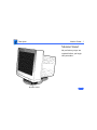
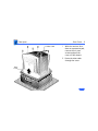
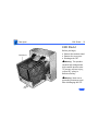
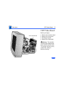
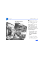
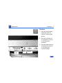
K Service Source
Apple Multiple Scan 17
Display
K Service Source
Basics
Apple Multiple Scan 17 Display
Basics
EEPROM Settings - 1
EEPROM Settings
Caution: To prevent data loss or corruption, always save
EEPROM settings before you replace the microprocessor
board. (See next page.)
See Troubleshooting for instructions on saving the EEPROM
settings from the old microprocessor board and restoring
the settings on the new microprocessor board.
If the settings are lost before they can be written to the new
EEPROM, the display will be impossible to repair, and the
whole display will need to be replaced.
Basics
EEPROM Settings - 2
Microprocessor Board
K Service Source
Specifications
Apple Multiple Scan 17 Display
Specifications
Characteristics - 1
Characteristics
Picture Tube
Screen Resolution
Scan Rates
Cable Connector
17-in. diagonal Trinitron CRT (16.1-in. viewable image)
Multiple scan
Bonded glass panel with antiglare/antistatic multilayer coating
640x480, 800x600, 832x624, or 1024x768
0.26-mm stripe pitch
Vertical refresh rate: 50 to 150 Hz
Horizontal scan rate: 29 to 82 kHz
Macintosh, XGA, VGA, SVGA, and VESA compatible
15-pin miniature D-type
Specifications
Input Signals
System
Requirements
Characteristics - 2
Video: red, green, and blue analog signals; RS-343A
standard;.714 V peak to peak; positive going
Sync on green: RS-343A compatible level;.286 V ± 10%
negative-going during blanking intervals
Separate Sync: 1 to 5 V peak to peak; negative or positive going
Composite Sync: 1 to 5 V peak to peak; negative or positive going
Power Macintosh, Macintosh Centris, Macintosh Quadra, or any
NuBus compatible Macintosh with a Macintosh Display Card
24AC.
Macintosh II family, PowerBooks, Duo and Mini Dock, Macintosh
Performa, Macintosh LC, LC II, LC III, and Macintosh
computers with Display Cards 4•8, 8•24, 8•24GC work in
640x480 mode. Other modes possible with additional adapters.
System software version 7.1 or later
Specifications
Controls and Ports - 3
Controls and Ports
User Controls
I/O Ports
Front panel: power, reset, and control buttons; brightness and
contrast controls
Additional controls available using the command button: horizontal
and vertical shift, horizontal and vertical size, rotation,
horizontal and vertical convergence, and color temperature
Automatic degauss at power-on; manual degauss by turning power
switch off, then on (capable of full degauss after monitor is
turned off for 20 minutes or more)
Two Apple Desktop Bus (ADB) ports and one ADB pass-through
port
Microphone: One input and one pass-through port
Headphone/Speaker: One input and one pass-through port
Specifications
Physical and Electrical - 4
Physical and Electrical
Power Supply
Size and Weight
Universal power supply
Voltage: 90–132 and 198–260 VAC, self-configuring
Frequency: 47–63 Hz
Power: 150 W maximum
Height: 16.5 in. (424 mm)
Width: 15.8 in. (405 mm)
Depth: 17.6 in. (452.3 mm)
Weight: 50.0 lb. (22.5 kg)
Specifications
Monitor Stand
Physical and Electrical - 5
Built-in, tilt-and-swivel stand
Three ADB ports (two ADB ports are in the front of the stand and
one ADB port is at the rear of the stand)
Sound-in and sound-out ports (to the CPU) at the rear of the base
Microphone input and speaker/headphone output ports at the front
of the base
Specifications
Environmental - 6
Environmental
Temperature
Altitude
Humidity
Power Savings
Feature
Operating: 50°F–104°F (10°C–40°C)
Storage: 32°F –140°F (0°C–60°C)
Shipping: -4°F–140°F (-40°C–60°C)
Operating: to 10,000 ft. (1,067 m)
Shipping: to 35,000 ft. (3,048 m)
Operating: 20–80% maximum, noncondensing
Storage: 5–90% maximum, noncondensing
Shipping: 5–95% maximum, noncondensing
Conforms to the Energy Star Program of the United States
Environmental Protection Agency
K Service Source
Troubleshooting
Apple Multiple Scan 17 Display
Troubleshooting
General - 1
General
The Symptom Charts included in this chapter will help you
diagnose specific symptoms related to your product. Because cures
are listed on the charts in the order of most likely solution, try
the first cure first. Verify whether or not the product continues to
exhibit the symptom. If the symptom persists, try the next cure.
(Note: If you have replaced a module, reinstall the original module
before you proceed to the next cure.)
If you are not sure what the problem is, or if the Symptom Charts
do not resolve the problem, refer to the Flowchart for the product
family.
For additional assistance, contact Apple Technical Support.
Troubleshooting
First Checklist - 2
First Checklist
Important: 54% of the Apple Multiple Scan 17 Display modules
returned for repair are found to be fully operational. Read this
checklist before you return a module. Prevent needless module
replacement and unnecessary time delays.
The Apple Multiple Scan 17 Display is not
fully compatible with all Macintosh
computers and PowerBooks.
If you suspect a loss of functionality, especially with the number
of screen resolutions available (in Control Panels), check the
Tech Info Library or contact Apple Technical Support.
Troubleshooting
First Checklist - 3
The CRT raster will not always resemble a
perfect rectangle.
CRT tolerances allow for some distortion. Additional distortion can
be caused by magnetized metal objects (desks, file cabinets, etc.).
Move the unit to a different location if you notice raster bowing or
bent raster edges.
Jitter, faint lines, or screen movement can be
caused by external interference such as
electronic devices and fluorescent lights.
Move the unit to another room or building to help determine if
external interference is the source of the problem.
Troubleshooting
First Checklist - 4
A misadjusted screen can mimic the
symptoms of deflection board or CRT
failures.
By performing the adjustment procedures, you might determine if
one or more of the adjustments is the cause of the problem.
CRTs rarely fail.
Needless CRT replacements can be prevented by checking display
adjustments, checking the possibility of other defective modules,
and accepting small imperfections in screen display.
If you have any doubts about whether a CRT is defective, contact
Apple Technical Support.
Troubleshooting
Display Setting Restoration/Connect the Hardware - 5
Display Setting Restoration
Each Multiple Scan 17 Display has an EEPROM (located on the
microprocessor controller board) that contains adjustment
information specific to that monitor. Before you replace the
microprocessor board, save this EEPROM information.
Use MacTest Pro Display Setting Restore Utility to preserve the
monitor adjustment settings.
Connect the Hardware
There are two ways to connect the hardware to use the MacTest Pro
Display Setting Restore Utility:
1 Connect a serial cable (MINI DIN-8) between the
malfunctioning display and a separate computer running
MacTest Pro. Use either the modem port or the printer port
on the computer. (If you use the printer port, AppleTalk
Troubleshooting
Display Setting Restoration/Connect the Hardware - 6
must be turned off). Also connect a power cable to the display.
Advantage: You do not have to shut down the host computer
or quit MacTest Pro to complete the repair.
Disadvantage: This method requires a separate host
computer (with display).
2
Connect the display as usual, using a video cable and power
cable. Also, connect a serial cable (MINI DIN-8) between the
display and either the modem or printer port on the
computer.
Advantage: This method lends itself to on-site repair; the
display under repair is the only display required.
Disadvantage: Since the microprocessor board on the display
needs to be replaced, the display may not be working well
enough to view this utility in MacTest Pro.
Troubleshooting
Display Setting Restoration/Save the EEPROM Information - 7
Another disadvantage is that after creating the data file from
the old EEPROM, you must quit MacTest Pro and shut down
the computer to install the new EEPROM.
Save the EEPROM Information
To save information from the old EEPROM, create a data file:
1
2
3
4
Start MacTest Pro.
Choose “Apple Multiple Scan 17 Display.”
Select “Test.”
Click “Create File.”
Install the Microprocessor Board
See Take Apart for instructions on installing the new
microprocessor board.
Troubleshooting
Display Setting Restoration/Restore the EEPROM Information After the new microprocessor board is installed, the new EEPROM
will have default settings that allow you to read the display, but
with difficulty. When the settings from the old EEPROM are
transferred to the new EEPROM, the display should be clear and
the last color temperature mode chosen restored.
Restore the EEPROM Information
To download the saved adjustment information to the new EEPROM,
1
2
3
4
Start MacTest Pro.
Choose “Apple Multiple Scan 17 Display.”
Select “Test.”
Click “Write File.”
Troubleshooting
Display Setting Restoration - 9
Caution: Make certain that you are aware of the following
important information about the EEPROM data file. If data is lost
or corrupted, you will have to return the display to Apple for
repair.
• Make sure that the data in the saved file is written back to the
display used to create the file. Each display is unique, so
writing the wrong data to a display may cause severe
adjustment problems.
• Make sure that the data file is deleted after writing the data
back to the display. This erasure ensures that data from one
display is not accidentally written to another.
• Do not delete the new data file before it’s written to the new
EEPROM. If the file is lost before the data can be written to the
new EEPROM, the repair will be impossible to complete and the
whole display will need to be returned.
Troubleshooting
CRT - 10
CRT
If the monitor shuts down shortly after powering up, follow this
procedure to determine if the CRT is defective:
1 Refer to Take Apart to remove the monitor stand, remove the
rear cover, discharge the CRT, remove the EMI shield.
2 With the power off, insert a nonconductive shield (such as a
strip of plastic or cardboard) between the CRT/video board
and the main deflection board to shield both boards from
potential shorts.
3 Note: Twisting, bending, or applying force to the CRT/video
board could damage the neck of the CRT. Be sure to pull the
CRT/video board straight off the CRT.
Loosen the mounting screw on the neck clamp.
4
Without disconnecting any cables, pull the CRT/video board
straight off the neck of the CRT (about 3/4 inch) until the
board disconnects from the pins.
Troubleshooting
CRT - 11
5
6
7
Rest the CRT/video board on the nonconductive shield.
Connect the monitor to a computer.
Plug in the power cable and turn on the monitor.
• If the power indicator light stays on, the CRT is defective.
• If the monitor shuts down immediately or after a few
seconds, replace the main deflection board.
Troubleshooting
Symptom Charts/Raster - 12
Symptom Charts
Raster
No raster; power
indicator light on
1
Raster edges have
color blotches when
displaying an allwhite screen
1
2
2
Ensure monitor’s video cable is properly connected to
computer or video card in the computer.
Replace main deflection board.
Degauss monitor with an external degaussing coil.
Move monitor to different location and repeat degaussing
procedure.
Note: This symptom is caused by strong magnetic fields in the
environment. Exchanging boards will not cure the symptom. Refer
to “First Checklist” in this chapter.
Troubleshooting
Symptom Charts/Raster (Continued) - 13
Raster
Oversized raster;
menu bar might be
partially cut off;
adjustments have no
effect on raster
(Continued)
Replace main deflection board, and without disconnecting
microprocessor board, check its revision level.
Important: On the component side of the board, look for a white
mark on the upper left corner and a 9-digit number that ends in
-11, -12, or -13.
If you see “-12” and a white mark or “-13” and no white
mark, you have an updated board. No board replacement required.
If you see “-11” or “-12” and no white mark, replace the
microprocessor board with an updated board after downloading
settings as described in “Display Setting Restoration” in this
chapter.
Caution: To prevent data loss or corruption, always save
EEPROM settings before you replace the microprocessor board.
Troubleshooting
Symptom Charts/Power - 14
Power
No power; power
indicator light off
1
2
3
Monitor shuts down
1
2
3
4
Check that power cord is properly connected to monitor and
live power source.
Ensure monitor’s video cable is properly connected to
computer or video card in the computer.
Replace main deflection board.
Ensure monitor’s video cable is properly connected to
computer or video card in the computer.
Determine if CRT is the cause by following the “CRT”
procedure in this chapter.
If CRT is not the cause, replace main deflection board.
Replace CRT/video board.
Troubleshooting
Symptom Charts/Indicator Lights - 15
Indicator Lights
Convergence
indicator light blinks
or stays on; power
indicator light might
also blink
Replace microprocessor board after downloading settings as
described in “Display Setting Restoration” in this chapter.
Caution: To prevent data loss or corruption, always save
EEPROM settings before you replace the microprocessor board.
Troubleshooting
Symptom Charts/Indicator Lights (Continued) - 16
Indicator Lights
Rotation indicator
light blinks or stays
on; power indicator
light might also blink
(Continued)
Replace main deflection board.
Troubleshooting
Symptom Charts/Indicator Lights (Continued) - 17
Indicator Lights
Size indicator light
blinks or stays on;
power indicator light
might also blink
1
2
3
(Continued)
Replace main deflection board.
Replace CRT/video board.
Replace microprocessor board after downloading settings as
described in “Display Setting Restoration” in this chapter.
Caution: To prevent data loss or corruption, always save
EEPROM settings before you replace the microprocessor
board.
Troubleshooting
Symptom Charts/Indicator Lights (Continued) - 18
Indicator Lights
Centering indicator
light blinks or stays
on; power indicator
light might also blink
1
2
(Continued)
Replace main deflection board.
Replace microprocessor board after downloading settings as
described in “Display Setting Restoration” in this chapter.
Caution: To prevent data loss or corruption, always save
EEPROM settings before you replace the microprocessor
board.
Troubleshooting
Symptom Charts/Miscellaneous - 19
Miscellaneous
Unable to download
saved adjustment
settings to new
microprocessor board
1
Picture has vertical
jitter
1
Move monitor to different location and see if symptom
persists.
Note: This symptom is often caused by electromagnetic
interference (electronic devices, fluorescent lights, power
lines, etc.). Refer to “First Checklist” in this chapter.
2
Replace microprocessor board after downloading settings as
described in “Display Setting Restoration” in this chapter.
Caution: To prevent data loss or corruption, always save
EEPROM settings before you replace the microprocessor
board.
2
Check that your version of Display Setting Restore Utility
matches the current version in the Diagnostics folder on
Service Source CD.
Contact Apple Technical Support.
Troubleshooting
Symptom Charts/Miscellaneous (Continued) - 20
Miscellaneous
Thin horizontal lines
on screen
(Continued)
Displays larger than 15 inches with tron-style CRTs typically
have two wires, each about one-quarter to one-third of the way
from the top and bottom of the display image. These supporting
wires, which are thinner than a human hair, stabilize the
aperture grill against shocks. The lines are common to all tronstyle displays and are not screen defects. The lines cannot be
adjusted out or eliminated by repairing or replacing modules in
the display.
K Service Source
Take Apart
Apple Multiple Scan 17 Display
Take Apart
Monitor Stand - 1
Monitor Stand
No preliminary steps are
required before you begin
this procedure.
Monitor Stand
Take Apart
Monitor Stand - 2
1
Screw
2
With the monitor facedown on a protective pad,
swivel the base to access
the monitor stand
mounting screw.
Remove the mounting
screw.
Take Apart
Monitor Stand - 3
3
4
Lift the monitor stand
out of the bezel.
If you do not plan to work
on the monitor, return
the monitor to an
upright position on the
protective pad.
Take Apart
Monitor Stand Cables - 4
Monitor Stand
Cables
Sound-In
Connector
Before you begin, remove
the monitor stand.
Note: The monitor stand
includes sound-in and
sound-out cables and an
ADB speaker board. You can
replace the monitor stand as
an assembly, or you can
replace its parts
individually.
Sound-Out
Connector
Take Apart
Screw
Monitor Stand Cables - 5
Tilt Platform
Washer
1
Remove the mounting
plate (with washer) and
separate the tilt
platform from the
swivel platform.
Replacement Note:
When replacing the tilt
and swivel platforms,
align the arrows etched
on the platforms with
the front of the base.
Mounting Plate
Swivel Platform
Take Apart
Monitor Stand Cables - 6
Bottom of Base
2
Screw
Tab
3
Tab
Screw
Tab
Screw
Tab
Sound-Out Connector
Top of Base
Remove the three
screws, push out the
four release tabs, and
separate the bottom from
the top of the base.
Place the bottom of the
base on the protective
pad.
Take Apart
Monitor Stand Cables - 7
Mounting Brackets
4
ADB Speaker Board
Sound-In
Connector
5
6
Mounting
Brackets
Sound Cables
Disconnect the sound-in
and sound-out cables
from the ADB speaker
board.
Remove the ADB speaker
board (if defective).
Unlace the defective
cable(s) from the
bottom of the base and
remove the cables from
the plastic mounting
bracket(s).
Take Apart
Rear Cover - 8
Rear Cover
Before you begin, remove
the monitor stand.
This product
contains high voltage and a
high-vacuum picture tube.
To prevent serious injury,
review CRT safety in
Bulletins/Safety.
±Warning:
Rear
Cover
Take Apart
Rear Cover - 9
Video Cable
1
2
Rear
Cover
With the monitor facedown on a protective pad,
remove the six case
screws and pull the
cover off the chassis.
Route the video cable
through the cover.
Take Apart
EMI Shield - 10
EMI Shield
EMI Shield
Before you begin,
• Remove the monitor stand
• Remove the rear cover
• Discharge the CRT
This product
contains high voltage and a
high-vacuum picture tube.
To prevent serious injury,
review CRT safety in
Bulletins/Safety.
±Warning:
Warning: Never use a
grounding wriststrap until
after discharging the CRT.
±
Take Apart
EMI Shield - 11
Note: The EMI shield is not
replaceable.
6
5
1
1
2
4
3
Remove the six screws
from the shield.
Take Apart
EMI Shield - 12
2
3
Slide the shield toward
the back of the monitor.
Bow the sides of the
shield out and lift off the
shield.
Take Apart
CRT/Video Board - 13
CRT/Video Board
CRT/Video Board
Before you begin,
• Remove the monitor stand
• Remove the rear cover
• Discharge the CRT
• Remove the EMI shield
Warning: This product
contains high voltage and a
high-vacuum picture tube.
To prevent serious injury,
review CRT safety in
Bulletins/Safety.
±
Take Apart
CRT/Video Board - 14
CRT/Video Board Shield
Ground Strap
Flyback
Transformer
Cable
Ties
Never use a
grounding wriststrap until
after discharging the CRT.
±Warning:
Caution: When removing
the ground strap and
flyback transformer cable
from the CRT/video board,
avoid excessive pressure on
the neck of the CRT.
1
2
Disconnect the ground
strap from the front of
the CRT/video board
shield.
Disconnect the flyback
transformer cable from
the CRT/video board.
Take Apart
CRT/Video Board - 15
CRT/Video Board Shield
Ground Strap
Flyback
Transformer
Cable
Ties
3
Remove the flyback
transformer cable from
the cable ties on the
CRT/video board shield.
Take Apart
CRT/Video Board - 16
4
CN307
CN303
CN304
Caution: When
disconnecting the
following cables from
the CRT/video board,
avoid excessive pressure
on the neck of the CRT.
Disconnect these cables
from the CRT/video
board:
• 9-wire video cable
(CN307)
• 8-wire
microprocessor board
cable (CN303)
• 13-wire
microprocessor board
cable (CN304)
Take Apart
CRT/Video Board - 17
5
CN305
CN301
Caution: When
disconnecting the
following cables from
the CRT/video board,
avoid excessive pressure
on the neck of the CRT.
Disconnect these cables
from the CRT/video
board:
• 1-wire ground cable
(CN301)
• 11-wire power cable
(CN305)
Take Apart
CRT/Video Board - 18
6
Caution: When
removing the video
cable clip screw from
the CRT/video board, be
careful not to apply
excessive pressure to
the neck of the CRT.
Remove the screw
securing the video cable
clip to the CRT/video
board shield.
Video
Cable Clip
Screw
Take Apart
CRT/Video Board - 19
7
NTC
Connector
Screw
CRT/Video Board
8
Caution: Twisting,
bending, or applying
force to the CRT/video
board could damage the
neck of the CRT. Be sure
to pull the CRT/video
board straight off the
CRT.
Disconnect the NTC
connector.
Loosen the mounting
screw and pull the CRT/
video board straight off
the neck of the CRT.
Take Apart
Video Cable - 20
Video Cable
Before you begin,
• Remove the monitor stand
• Remove the rear cover
• Discharge the CRT
• Remove the EMI shield
This product
contains high voltage and a
high-vacuum picture tube.
To prevent serious injury,
review CRT safety in
Bulletins/Safety.
±Warning:
Never use a
grounding wriststrap until
after discharging the CRT.
±Warning:
Video Cable
Take Apart
Video Cable - 21
1
CN307
CRT/Video
Board
Caution: When
removing the video
cable from the CRT/
video board, be careful
to avoid excessive
pressure on the neck of
the CRT.
Disconnect the 9-wire
video cable from the
CRT/video board
(CN307).
Take Apart
Video Cable - 22
2
Cable Brace
Press down on the
plastic latch and push
the top of the cable brace
out of the chassis.
Take Apart
Video Cable - 23
3
4
Cable Mounting
Screw
Cable Mounting
Screw
Video Cable
Remove the two cable
mounting screws.
Remove the video cable.
Take Apart
Serial I/O Board - 24
Serial I/O Board
Before you begin,
• Remove the monitor stand
• Remove the rear cover
• Discharge the CRT
• Remove the EMI shield
Warning: This product
contains high voltage and a
high-vacuum picture tube.
To prevent serious injury,
review CRT safety in
Bulletins/Safety.
±
Never use a
grounding wriststrap until
after discharging the CRT.
±Warning:
Serial I/O
Board
Take Apart
Serial I/O Board - 25
1
2
5-Pin Serial
Communications
Cable
3
Serial I/O
Board
Screws
Disconnect the 5-pin
serial communications
cable from the serial I/O
board.
Remove the two screws
securing the serial I/O
board to the rear panel.
Lift out the serial I/O
board.
Take Apart
AC Inlet - 26
AC Inlet
Before you begin,
• Remove the monitor stand
• Remove the rear cover
• Discharge the CRT
• Remove the EMI shield
Warning: This product
contains high voltage and a
high-vacuum picture tube.
To prevent serious injury,
review CRT safety in
Bulletins/Safety.
±
Never use a
grounding wriststrap until
after discharging the CRT.
±Warning:
AC Inlet
Take Apart
AC Inlet - 27
1
Ground Wire
2
Screw
CN603
Remove the screw (with
captive lockwasher) and
the inlet assembly
ground wire from the
chassis.
Disconnect the 2-wire
power inlet cable from
connector CN603 on the
main deflection board.
Take Apart
AC Inlet - 28
3
4
Remove the two screws
securing the AC inlet
assembly to the chassis.
Pull the inlet assembly
through the hole in the
chassis.
Replacement Note:
When replacing the AC
inlet assembly, insert
the power inlet cable and
ground wire through the
chassis mounting hole
before inserting the
circuit card end of the AC
inlet assembly.
AC Inlet
Take Apart
Microprocessor Board - 29
Microprocessor
Board
Before you begin,
• Save EEPROM settings
• Remove the monitor stand
• Remove the rear cover
• Discharge the CRT
• Remove the EMI shield
Important: Before you
replace the microprocessor
board, save the EEPROM
settings. See
Troubleshooting for
instructions.
Microprocessor Board
Take Apart
Microprocessor Board - 30
This product
contains high voltage and a
high-vacuum picture tube.
To prevent serious injury,
review CRT safety in
Bulletins/Safety.
±Warning:
Warning: Never use a
grounding wriststrap until
after discharging the CRT.
±
Take Apart
Microprocessor Board - 31
Important: Make sure you
save the EEPROM settings
before replacing the
microprocessor board.
CN901
1
CN902
CN908
CN907
Disconnect these cables
from the
microprocessor board:
• 13-wire cable
(CN901)
• 8-wire cable
(CN902)
• 5-wire cable
(CN908)
• 6-wire cable
(CN907)
Take Apart
Microprocessor Board - 32
2
Clip
Release the plastic clip
at the top of the
microprocessor board.
Take Apart
Microprocessor Board - 33
3
4
Microprocessor
Board Connector
Pivot the
microprocessor board
so it lies flat.
Pull the microprocessor
board out from its
mating connector and
remove the board.
Take Apart
Main Deflection Board - 34
Main Deflection
Board
Main
Deflection
Board
Before you begin,
• Remove the monitor stand
• Remove the rear cover
• Discharge the CRT
• Disconnect the anode cap
• Remove the EMI shield
• Remove the
microprocessor board
Important: If replacing the
microprocessor board as
well as the main deflection
board, save the EEPROM
settings before replacement.
Take Apart
Main Deflection Board - 35
Flyback
Transformer
Cable
This product
contains high voltage and a
high-vacuum picture tube.
To prevent serious injury,
review CRT safety in
Bulletins/Safety.
±Warning:
Never use a
grounding wriststrap until
after discharging the CRT.
±Warning:
Cable Ties
1
CN505
CN601
CN603
Disconnect these cables
from the main deflection
board:
• CN603
• CN601
• CN505
Take Apart
Main Deflection Board - 36
Flyback
Transformer
Cable
2
Cable Ties
3
CN505
CN601
CN603
Caution: When
removing the flyback
transformer cable from
the CRT/video board,
avoid pressure on the
neck of the CRT.
Disconnect the flyback
transformer cable from
the CRT/video board.
Remove the flyback
transformer cable from
the cable ties on the
CRT/video board shield.
Take Apart
Main Deflection Board - 37
4
CN1400
Serial I/O
Board
Disconnect connector
CN1400 from the serial
I/O board.
Take Apart
Main Deflection Board - 38
5
CN307
Video Cable Clip
CRT/Video
Board
6
Disconnect the 9-wire
video cable (CN307)
from the CRT/video
board.
Remove the screw
securing the video cable
clip to the CRT/video
board shield.
Take Apart
Main Deflection Board - 39
7
Flyback
Transformer
Cable
Caution: When
removing the ground
cable from the CRT/
video board, avoid
excessive pressure on
the neck of the CRT.
Disconnect the 1-wire
ground cable (CN301)
from the CRT/video
board.
CN301
Take Apart
Main Deflection Board - 40
8
Main
Deflection
Board
Screw
9
Screw
With the monitor facedown on a protective pad,
remove the four screws
securing the main
deflection board to the
housing.
Note: Only two screws
are shown. The other two
screws are on the right
side of the main
deflection board.
Lift out the main
deflection board.
Take Apart
Main Deflection Board - 41
10 Remove the two screws
securing the rear panel
to the bottom chassis.
11 Remove the rear panel.
Screw
Rear Panel
Screw
Take Apart
Control Panel Board - 42
Control Panel
Board
Before you begin,
• Remove the monitor stand
• Remove the rear cover
• Discharge the CRT
• Disconnect the anode cap
• Remove the EMI shield
• Remove the main
deflection board
This product
contains high voltage and a
high-vacuum picture tube.
To prevent serious injury,
review CRT safety in
Bulletins/Safety.
±Warning:
Control Panel Board
Take Apart
Control Panel Board - 43
Never use a
grounding wriststrap until
after discharging the CRT.
±Warning:
1
2
Screw
Control Panel Board
Screw
Remove the two screws
securing the control
panel board support to
the front bezel.
Lift out the control panel
board and support.
Take Apart
Control Panel Board - 44
3
CN801
Latch
Latch
Latch
4
Latch
Disconnect the control
panel cable from the
control panel board
(CN801).
Simultaneously, release
each of the four plastic
latches at the rear of the
control panel board and
lift the board.
K Service Source
Adjustments
Apple Multiple Scan 17 Display
Adjustments
Brightness and Contrast - 1
Brightness and
Contrast
No preliminary steps are
required before you begin
this procedure.
Front Panel
Adjustments
Brightness and Contrast - 2
Brightness
1
2
Brightness
Controls
Press the up button to
increase the brightness.
Press the down button to
decrease the brightness.
Adjustments
Brightness and Contrast - 3
Contrast
1
2
Contrast
Controls
Press the left button to
decrease the contrast.
Press the right button
to increase the contrast.
Adjustments
Geometry - 4
Geometry
No preliminary steps are
required before you begin
this procedure.
Front Panel
Adjustments
Geometry - 5
Vertical Center
Crosshatch
1
2
Centering
Indicator
Light
Select
Button
Brightness
Controls
Press the select button
to turn on the centering
indicator light.
Press the up or down
button on the brightness
controls to move the
center of the picture up
or down.
Adjustments
Geometry - 6
Horizontal Center
Crosshatch
1
2
Centering
Indicator
Light
Select
Button
Contrast
Controls
Press the select button
to turn on the centering
indicator light.
Press the left or right
button on the contrast
controls to move the
center of the picture
left or right.
Adjustments
Geometry - 7
Vertical Size
Crosshatch
1
2
Size
Indicator
Light
Select
Button
Brightness
Controls
Press the select button
repeatedly until the size
indicator light goes on.
Press the up or down
button on the brightness
controls to increase or
decrease the size of the
picture.
Adjustments
Geometry - 8
Horizontal Size
Crosshatch
1
2
Size
Indicator
Light
Select
Button
Contrast
Controls
Press the select button
repeatedly until the size
indicator light goes on.
Press the left or right
button on the contrast
controls to decrease or
increase the size of the
picture.
Adjustments
Geometry - 9
Rotation
Crosshatch
1
2
3
Rotation
Indicator
Light
Select
Button
Brightness
Controls
Ê
Press the select button
repeatedly until the
rotation indicator light
goes on.
Press the up button on
the brightness controls
to tilt the picture
clockwise.
Press the down button on
the brightness controls
to tilt the picture
counterclockwise.
Adjustments
Geometry - 10
Shape
Crosshatch
1
2
3
Rotation
Indicator
Light
Select
Button
Contrast
Controls
Press the select button
repeatedly until the
rotation indicator light
goes on.
Press the left button on
the contrast controls to
bring in the sides of the
picture.
Press the right button on
the contrast controls to
expand the sides of the
picture.
Adjustments
Convergence - 11
Convergence
No preliminary steps are
required before you begin
this procedure.
Note: When the convergence
is set properly, the picture
is crisp and clear.
Front Panel
Adjustments
Convergence - 12
Vertical Convergence
Crosshatch
1
2
Convergence
Indicator
Light
3
Select
Button
Brightness
Controls
Press the select button
repeatedly until the
convergence indicator
light goes on.
Press the up button on
the brightness controls
to move the red signal up
and the blue signal down.
Press the down button on
the brightness controls
to move the red signal
down and the blue signal
up.
Adjustments
Convergence - 13
Horizontal
Convergence
Crosshatch
1
2
Convergence
Indicator
Light
3
Select
Button
Contrast
Controls
Press the select button
repeatedly until the
convergence indicator
light goes on.
Press the left button on
the contrast controls to
move the red signal to
the left and the blue
signal to the right.
Press the right button on
the contrast controls to
move the red signal to
the right and the blue
signal to the left.
Adjustments
Color Temperature - 14
Color Temperature
No preliminary steps are
required before you begin
this procedure.
Front Panel
Color temperature refers to
the intensity of the red/
green/blue signals sent to
the monitor. The color
temperature settings are
• 9300 K: white appears
bluish (default)
• 6500 K: white appears
page white
• 5000 K: white appears
reddish
Adjustments
Color Temperature - 15
Color temperature can be
changed to accommodate
preference or application
specifications.
Adjustments
Color Temperature - 16
1
Light
Color
Temperature
Indicator
Select
Button
Contrast
Controls
Press the select button
repeatedly until the
color temperature
indicator light goes on.
Note: The indicator may
or may not blink,
depending on the color
temperature selected:
• A steady light
indicates 9300 K
• A slow blinking light
indicates 6500 K
• A fast blinking light
indicates 5000 K
Adjustments
Color Temperature - 17
2
Light
3
Color
Temperature
Indicator
Select
Button
Contrast
Controls
Press the left button on
the contrast controls to
decrease the color
temperature.
Press the right button on
the contrast controls to
increase the color
temperature.
Adjustments
Factory Settings - 18
Factory Settings
No preliminary steps are
required before you begin
this procedure.
Front Panel
Important: The controls for
the monitor are set at the
factory. To fine-tune and
adjust the picture, use the
front panel controls. The
monitor will use your
settings each time the
computer is turned on. Use
the recall function to
return to factory settings.
Adjustments
Factory Settings - 19
Recall
Note: You can reset
brightness and contrast to
their factory levels;
however, you cannot reset
one or the other. You must
reset both controls.
Use a straightened paper
clip to push in the reset
button.
Reset
Button
Adjustments
Factory Settings - 20
Reset a Specific
Control
1
Picture Control
Indicator Lights
Reset
Button
Select
Button
2
Press the select button
repeatedly until the
indicator light of the
picture control you
want to reset (vertical
or horizontal center,
convergence, or color
temperature) goes on.
Use a straightened paper
clip to push in the reset
button.
The selected picture
control is reset to its
original level.
Adjustments
Factory Settings - 21
Reset All Controls
While holding down the
control button, push in the
reset button with a
straightened paper clip.
Control
Button
Reset
Button
All picture controls are
reset to their factory levels.
K Service Source
Exploded View
Apple Multiple Scan 17 Display
Exploded View
1
EMI Shield
(Not Offered)
922-0742
Bezel
922-0693
Serial I/O Board
922-0749
Video Cable
CRT
Assembly
(Not Offered)
922-0744
Rear Connector
Panel
922-0698
AC Inlet
922-0695
Microprocessor Control Board
922-0710
Cover
922-0694
Control
Panel
Board
661-0882
CRT/Video
Board
922-0818 Tilt/Swivel Base
661-0881
Main Deflection
Board
922-0709
Rear Housing