1
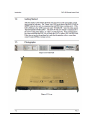
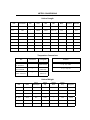
RAP-100
Remote Access Panel
Installation and Operation Manual
Part Number MN/RAP100.IOM
Revision 1
RAP-100
Remote Access Panel
Installation and Operation Manual
Comtech EFData is an ISO 9001
Registered Company.
Part Number MN/RAP100.IOM
Revision 1
December 8, 1999
Copyright © Comtech EFData, 2000. All rights reserved. Printed in the USA.
Comtech EFData, 2114 West 7th Street, Tempe, Arizona 85281 USA, (480) 333-2200, FAX: (480) 333-2161.
Errata A
Comtech EF Data Documentation Update
RAP-100
Remote Access Panel
Installation and Operation Manual
MN-RAP100.IOM REV 1
Original Manual Part Number/Rev: MN/RAP100.IOM Rev 1 Errata Number/ PLM Document ID: PLM CO Number: C‐0029408 Comments: The updated information will be in the next formal revision of the manual. ER-RAP100-EA1 Change: Added photographs to page 1‐2 ER-RAP100-EA1 Revision -
This document is not subject to revision/update!
PLM CO C-0029408
Page 1 of 2
ER-RAP100-EA1
Revision -
This document is not subject to revision/update!
PLM CO C-0029408
Page 2 of 2
Customer Support
Contact the Comtech EFData Customer Support Department for:
• Product support or training
• Information on upgrading or returning a product
• Reporting comments or suggestions concerning manuals
A Customer Support representative may be reached at:
Comtech EFData
Attention: Customer Support Department
2114 West 7th Street
Tempe, Arizona 85281 USA
(480) 333-2200 (Main Comtech EFData Number)
(480) 333-4357 (Customer Support Desk)
(480) 333-2161 FAX
or, E-Mail can be sent to the Customer Support Department at:
[email protected]
Contact us via the web at www.comtechefdata.com.
1. To return a Comtech EFData product (in-warranty and out-of-warranty) for
repair or replacement:
2. Request a Return Material Authorization (RMA) number from the Comtech
EFData Customer Support Department.
3. Be prepared to supply the Customer Support representative with the model
number, serial number, and a description of the problem.
4. To ensure that the product is not damaged during shipping, pack the product in
its original shipping carton/packaging.
5. Ship the product back to Comtech EFData. (Shipping charges should be prepaid.)
For more information regarding the warranty policies, see Warranty Policy, p. viii.
ii
Rev. 1
Table of Contents
Customer Support....................................................................................................................................................... ii
About this Manual .................................................................................................................................................... vii
Conventions and References................................................................................................................................... vii
Reporting Comments or Suggestions Concerning this Manual .............................................................................. vii
Warranty Policy ....................................................................................................................................................... viii
Limitations of Warranty ........................................................................................................................................ viii
Exclusive Remedies............................................................................................................................................... viii
Disclaimer ................................................................................................................................................................. viii
CHAPTER 1.
INTRODUCTION .................................................................................1–1
1.1
Equipment Use:.......................................................................................................................................... 1–1
1.2
Equipment Power: ..................................................................................................................................... 1–1
1.3
CSAT Interface: ......................................................................................................................................... 1–1
1.4
Getting Started:.......................................................................................................................................... 1–2
CHAPTER 2.
REDUNDANT CSAT CONTROL ........................................................2–1
2.1
RAP-100 Menus ......................................................................................................................................... 2–3
2.1.1 VOLTAGES Selection ............................................................................................................................ 2–3
2.1.2 SWITCHES Selection: ............................................................................................................................ 2–3
2.1.3 MODE Selection: .................................................................................................................................... 2–4
2.1.4 ONLINE Selection: ................................................................................................................................. 2–4
CHAPTER 3.
3.1
Rev. 1
ODU OPERATION ..............................................................................3–1
Front Panel ODU Operation..................................................................................................................... 3–1
iii
Preface
RAP-100 Remote Access Panel
3.2
MENU TREES................................................................................................................................. 3–2
3.2.1 SELECT .................................................................................................................................................. 3–2
3.2.2 ODU ........................................................................................................................................................ 3–2
3.2.3 (ODU,ENABLE) System Type ............................................................................................................... 3–2
3.2.4 (ODU,ENABLE) 1:1 ............................................................................................................................... 3–3
3.2.5 (ODU,ENABLE,1:1) RED BOX (Redundancy Controller Box) ............................................................ 3–3
3.2.6 (ODU,ENABLE,1:1,RED BOX) ONLINE............................................................................................. 3–3
3.2.7 (ODU,ENABLE,1:1,RED BOX) MODE ................................................................................................ 3–3
3.2.8 (ODU,ENABLE,1:1,RED BOX) SWITCHES........................................................................................ 3–4
3.2.9 (ODU,ENABLE,1:1,RED BOX) VOLTAGES....................................................................................... 3–4
3.2.10
(ODU,ENABLE,1:1,CSAT#1) Selections (ODU,ENABLE,1:1,CSAT#2) Selections
(ODU,ENABLE,STAND-ALONE) Selections.................................................................................................... 3–4
3.2.11
(ODU,ENABLE,1:1,CSAT#1) CONFIG (Confiuration) (ODU,ENABLE,1:1,CSAT#2) CONFIG
(Confiuration) (ODU,ENABLE,STAND-ALONE) CONFIG (Confiuration).................................................... 3–4
3.2.12
(ODU,ENABLE,1:1,CSAT#1,CONFIG) TRANSMITTER (ODU,ENABLE,1:1,CSAT#2,CONFIG)
TRANSMITTER (ODU,ENABLE,STAND-ALONE,CONFIG) TRANSMITTER........................................... 3–4
3.2.13
(ODU,ENABLE,1:1,CSAT#1,CONFIG,TRANSMITTER) FREQUENCY
(ODU,ENABLE,1:1,CSAT#2,CONFIG,TRANSMITTER) FREQUENCY (ODU,ENABLE,STANDALONE,CONFIG,TRANSMITTER) FREQUENCY.......................................................................................... 3–5
3.2.14
(ODU,ENABLE,1:1,CSAT#1,CONFIG,TRANSMITTER) ATTEN (Attenuation)
(ODU,ENABLE,1:1,CSAT#2,CONFIG,TRANSMITTER) ATTEN (Attenuation) (ODU,ENABLE,STANDALONE,CONFIG,TRANSMITTER) ATTEN (Attenuation) .............................................................................. 3–5
3.2.15
(ODU,ENABLE,1:1,CSAT#1,CONFIG,TRANSMITTER) AMPLIFIER
(ODU,ENABLE,1:1,CSAT#2,CONFIG,TRANSMITTER) AMPLIFIER (ODU,ENABLE,STANDALONE,CONFIG,TRANSMITTER) AMPLIFIER............................................................................................. 3–5
3.2.16
(ODU,ENABLE,1:1,CSAT#1,CONFIG,TRANSMITTER) MUTE
(ODU,ENABLE,1:1,CSAT#2,CONFIG,TRANSMITTER) MUTE (ODU,ENABLE,STANDALONE,CONFIG,TRANSMITTER) MUTE ...................................................................................................... 3–5
3.2.17
(ODU,ENABLE,1:1,CSAT#1,CONFIG,TRANSMITTER) SLOPE
(ODU,ENABLE,1:1,CSAT#2,CONFIG,TRANSMITTER) SLOPE (ODU,ENABLE,STANDALONE,CONFIG,TRANSMITTER) SLOPE...................................................................................................... 3–6
3.2.18
(ODU,ENABLE,1:1,CSAT#1,CONFIG,TRANSMITTER,SLOPE) MANUAL
(ODU,ENABLE,1:1,CSAT#2,CONFIG,TRANSMITTER,SLOPE) MANUAL (ODU,ENABLE,STANDALONE,CONFIG,TRANSMITTER,SLOPE) MANUAL ................................................................................... 3–6
3.2.19
(ODU,ENABLE,1:1,CSAT#1,CONFIG) RECEIVER (ODU,ENABLE,1:1,CSAT#2,CONFIG)
RECEIVER (ODU,ENABLE,STAND-ALONE,CONFIG) RECEIVER............................................................ 3–6
3.2.20
(ODU,ENABLE,1:1,CSAT#1,CONFIG,RECEIVER) FREQUENCY
(ODU,ENABLE,1:1,CSAT#2,CONFIG,RECEIVER) FREQUENCY (ODU,ENABLE,STANDALONE,CONFIG,RECEIVER) FREQUENCY .................................................................................................. 3–6
3.2.21
(ODU,ENABLE,1:1,CSAT#1,CONFIG,RECEIVER) ATTEN (Attenuation)
(ODU,ENABLE,1:1,CSAT#2,CONFIG,RECEIVER) ATTEN (Attenuation) (ODU,ENABLE,STANDALONE,CONFIG,RECEIVER) ATTEN (Attenuation)....................................................................................... 3–7
3.2.22
(ODU,ENABLE,1:1,CSAT#1,CONFIG,RECEIVER) MUTE
(ODU,ENABLE,1:1,CSAT#2,CONFIG,RECEIVER) MUTE (ODU,ENABLE,STANDALONE,CONFIG,RECEIVER) MUTE.............................................................................................................. 3–7
3.2.23
(ODU,ENABLE,1:1,CSAT#1,CONFIG,RECEIVER) SLOPE
(ODU,ENABLE,1:1,CSAT#2,CONFIG,RECEIVER) SLOPE (ODU,ENABLE,STANDALONE,CONFIG,RECEIVER) SLOPE .............................................................................................................. 3–7
3.2.24
(ODU,ENABLE,1:1,CSAT#1,CONFIG,RECEIVER,SLOPE) MANUAL
(ODU,ENABLE,1:1,CSAT#2,CONFIG,RECEIVER,SLOPE) MANUAL (ODU,ENABLE,STANDALONE,CONFIG,RECEIVER,SLOPE) MANUAL............................................................................................ 3–7
3.2.25
(ODU,ENABLE,1:1,CSAT#1,CONFIG,RECEIVER) LNA
(ODU,ENABLE,1:1,CSAT#2,CONFIG,RECEIVER) LNA (ODU,ENABLE,STANDALONE,CONFIG,RECEIVER) LNA.................................................................................................................. 3–8
iv
Rev. 1
RAP-100 Remote Access Panel
Preface
3.2.26
(ODU,ENABLE,1:1,CSAT#1,CONFIG,RECEIVER,LNA) STATE
(ODU,ENABLE,1:1,CSAT#2,CONFIG,RECEIVER,LNA) STATE (ODU,ENABLE,STANDALONE,CONFIG,RECEIVER,LNA) STATE..................................................................................................... 3–8
3.2.27
(ODU,ENABLE,1:1,CSAT#1,CONFIG,RECEIVER,LNA) CAL (Calibrate)
(ODU,ENABLE,1:1,CSAT#2,CONFIG,RECEIVER,LNA) CAL (Calibrate) (ODU,ENABLE,STANDALONE,CONFIG,RECEIVER,LNA) CAL (Calibrate)....................................................................................... 3–8
3.2.28
(ODU,ENABLE,1:1,CSAT#1,CONFIG,RECEIVER,LNA) CURR-WINDOW
(ODU,ENABLE,1:1,CSAT#2,CONFIG,RECEIVER,LNA) CURR-WINDOW (ODU,ENABLE,STANDALONE,CONFIG,RECEIVER,LNA) CURR-WINDOW ................................................................................... 3–8
3.2.29
(ODU,ENABLE,1:1,CSAT#1,CONFIG,RECEIVER,LNA) FAULT-LOGIC
(ODU,ENABLE,1:1,CSAT#2,CONFIG,RECEIVER,LNA) FAULT-LOGIC (ODU,ENABLE,STANDALONE,CONFIG,RECEIVER,LNA) FAULT-LOGIC....................................................................................... 3–9
3.2.30
(ODU,ENABLE,1:1,CSAT#1,CONFIG) MISCELLANEOUS
(ODU,ENABLE,1:1,CSAT#2,CONFIG) MISCELLANEOUS (ODU,ENABLE,STAND-ALONE,CONFIG)
MISCELLANEOUS............................................................................................................................................. 3–9
3.2.31
(ODU,ENABLE,1:1,CSAT#1,CONFIG,MISCELLANEOUS) COLD-START
(ODU,ENABLE,1:1,CSAT#2,CONFIG,MISCELLANEOUS) COLD-START (ODU,ENABLE,STANDALONE,CONFIG,MISCELLANEOUS) COLD-START.................................................................................... 3–9
3.2.32
(ODU,ENABLE,1:1,CSAT#1,CONFIG,MISCELLANEOUS) AFR(Auto Flt Rec)
(ODU,ENABLE,1:1,CSAT#2,CONFIG,MISCELLANEOUS) AFR(Auto Flt Rec) (ODU,ENABLE,STANDALONE,CONFIG,MISCELLANEOUS) AFR(Auto Flt Rec) ............................................................................. 3–9
3.2.33
(ODU,ENABLE,1:1,CSAT#1,CONFIG,MISCELLANEOUS) XREF(Ext Ref)
(ODU,ENABLE,1:1,CSAT#2,CONFIG,MISCELLANEOUS) XREF(Ext Ref) (ODU,ENABLE,STANDALONE,CONFIG,MISCELLANEOUS) XREF(Ext Ref) ................................................................................. 3–10
3.2.34
(ODU,ENABLE,1:1,CSAT#1,CONFIG,MISCELLANEOUS) REF-ADJUST
(ODU,ENABLE,1:1,CSAT#2,CONFIG,MISCELLANEOUS) REF-ADJUST (ODU,ENABLE,STANDALONE,CONFIG,MISCELLANEOUS) REF-ADJUST ................................................................................... 3–10
3.2.35
(ODU,ENABLE,1:1,CSAT#1,CONFIG,MISCELLANEOUS) RTC
(ODU,ENABLE,1:1,CSAT#2,CONFIG,MISCELLANEOUS) RTC (ODU,ENABLE,STANDALONE,CONFIG,MISCELLANEOUS) RTC................................................................................................... 3–10
3.2.36
(ODU,ENABLE,1:1,CSAT#1) INFO (Information) (ODU,ENABLE,1:1,CSAT#2) INFO
(Information) (ODU,ENABLE,STAND-ALONE) INFO (Information).......................................................... 3–10
3.2.37
(ODU,ENABLE,1:1,CSAT#1,INFO) MODEL (ODU,ENABLE,1:1,CSAT#2,INFO) MODEL
(ODU,ENABLE,STAND-ALONE,INFO) MODEL......................................................................................... 3–11
3.2.38
(ODU,ENABLE,1:1,CSAT#1,INFO) TRANSMITTER (ODU,ENABLE,1:1,CSAT#2,INFO)
TRANSMITTER (ODU,ENABLE,STAND-ALONE,INFO) TRANSMITTER ............................................. 3–11
3.2.39
(ODU,ENABLE,1:1,CSAT#1,INFO) RECEIVER (ODU,ENABLE,1:1,CSAT#2,INFO) RECEIVER
(ODU,ENABLE,STAND-ALONE,INFO) RECEIVER ................................................................................... 3–11
3.2.40
(ODU,ENABLE,1:1,CSAT#1,INFO) MISC (ODU,ENABLE,1:1,CSAT#2,INFO) MISC
(ODU,ENABLE,STAND-ALONE,INFO) MISC ............................................................................................. 3–11
3.2.41
(ODU,ENABLE,1:1,CSAT#1,INFO) LNA (ODU,ENABLE,1:1,CSAT#2,INFO) LNA
(ODU,ENABLE,STAND-ALONE,INFO) LNA............................................................................................... 3–11
3.2.42
(ODU,ENABLE,1:1,CSAT#1) MONITOR (ODU,ENABLE,1:1,CSAT#2) MONITOR
(ODU,ENABLE,STAND-ALONE) MONITOR................................................................................................ 3–12
3.2.43
(ODU,ENABLE,1:1,CSAT#1,MONITOR) TX (Transmitter)
(ODU,ENABLE,1:1,CSAT#2,MONITOR) TX (Transmitter) (ODU,ENABLE,STAND-ALONE,MONITOR)
TX (Transmitter)................................................................................................................................................. 3–12
3.2.44
(ODU,ENABLE,1:1,CSAT#1,MONITOR) RX (Receiver) (ODU,ENABLE,1:1,CSAT#2,MONITOR)
RX (Receiver) (ODU,ENABLE,STAND-ALONE,MONITOR) RX (Receiver) .............................................. 3–12
3.2.45
(ODU,ENABLE,1:1,CSAT#1,MONITOR) MISC (ODU,ENABLE,1:1,CSAT#2,MONITOR) MISC
(ODU,ENABLE,STAND-ALONE,MONITOR) MISC..................................................................................... 3–12
3.2.46
(ODU,ENABLE,1:1,CSAT#1,MONITOR) PWR SUPP1 (ODU,ENABLE,1:1,CSAT#2,MONITOR)
PWR SUPP1 (ODU,ENABLE,STAND-ALONE,MONITOR) PWR SUPP1 .................................................. 3–12
3.2.47
(ODU,ENABLE,1:1,CSAT#1,MONITOR) PWR SUPP2 (ODU,ENABLE,1:1,CSAT#2,MONITOR)
PWR SUPP2 (ODU,ENABLE,STAND-ALONE,MONITOR) PWR SUPP2 .................................................. 3–13
Rev. 1
v
Preface
RAP-100 Remote Access Panel
3.2.48
(ODU,ENABLE,1:1,CSAT#1) ALARMS (ODU,ENABLE,1:1,CSAT#2) ALARMS
(ODU,ENABLE,STAND-ALONE) ALARMS.................................................................................................. 3–13
3.2.49
(ODU,ENABLE,1:1,CSAT#1,ALARMS) CURRENT (ODU,ENABLE,1:1,CSAT#2,ALARMS)
CURRENT (ODU,ENABLE,STAND-ALONE,ALARMS) CURRENT......................................................... 3–13
3.2.50
(ODU,ENABLE,1:1,CSAT#1,ALARMS) STORED (ODU,ENABLE,1:1,CSAT#2,ALARMS)
STORED (ODU,ENABLE,STAND-ALONE,ALARMS) STORED................................................................ 3–13
3.2.51
(ODU,ENABLE,1:1,CSAT#1,ALARMS,STORED) VIEW
(ODU,ENABLE,1:1,CSAT#2,ALARMS,STORED) VIEW (ODU,ENABLE,STANDALONE,ALARMS,STORED) VIEW................................................................................................................ 3–14
3.2.52
(ODU,ENABLE,1:1,CSAT#1,ALARMS,STORED) CLEAR ALL
(ODU,ENABLE,1:1,CSAT#2,ALARMS,STORED) CLEAR ALL (ODU,ENABLE,STANDALONE,ALARMS,STORED) CLEAR ALL..................................................................................................... 3–14
vi
Rev. 1
RAP-100 Remote Access Panel
Preface
About this Manual
This manual provides installation and operation information for the Comtech EFData
RAP-100 Remote Access Panel. This is a technical document intended for earth station
engineers, technicians, and operators responsible for the operation and maintenance of
the RAP-100.
Conventions and References
Cautions and Warnings
CAUTION
CAUTION indicates a hazardous situation that, if not avoided, may result in
minor or moderate injury. CAUTION may also be used to indicate other
unsafe practices or risks of property damage.
WARNING indicates a potentially hazardous situation that, if not avoided,
could result in death or serious injury.
WARNING
Metric Conversion
Metric conversion information is located on the inside back cover of this manual. This
information is provided to assist the operator in cross-referencing English to Metric
conversions.
Trademarks
Other product names mentioned in this manual may be trademarks or registered
trademarks of their respective companies and are hereby acknowledged.
Reporting Comments or Suggestions Concerning this Manual
Comments and suggestions regarding the content and design of this manual will be
appreciated. To submit comments, please contact the Comtech EFData Customer Support
Department.
Rev. 1
vii
Preface
RAP-100 Remote Access Panel
Warranty Policy
This Comtech EFData product is warranted against defects in material and workmanship
for a period of two years from the date of shipment. During the warranty period, Comtech
EFData will, at its option, repair or replace products that prove to be defective.
For equipment under warranty, the customer is responsible for freight to Comtech
EFData and all related custom, taxes, tariffs, insurance, etc. Comtech EFData is
responsible for the freight charges only for return of the equipment from the factory to
the customer. Comtech EFData will return the equipment by the same method (i.e., Air,
Express, Surface) as the equipment was sent to Comtech EFData.
Limitations of Warranty
The foregoing warranty shall not apply to defects resulting from improper installation or
maintenance, abuse, unauthorized modification, or operation outside of environmental
specifications for the product, or, for damages that occur due to improper repackaging of
equipment for return to Comtech EFData.
No other warranty is expressed or implied. Comtech EFData specifically disclaims the
implied warranties of merchantability and fitness for particular purpose.
Exclusive Remedies
The remedies provided herein are the buyer's sole and exclusive remedies. Comtech
EFData shall not be liable for any direct, indirect, special, incidental, or consequential
damages, whether based on contract, tort, or any other legal theory.
Disclaimer
Comtech EFData has reviewed this manual thoroughly in order that it will be an easy-touse guide to your equipment. All statements, technical information, and
recommendations in this manual and in any guides or related documents are believed
reliable, but the accuracy and completeness thereof are not guaranteed or warranted, and
they are not intended to be, nor should they be understood to be, representations or
warranties concerning the products described. Further, Comtech EFData reserves the
right to make changes in the specifications of the products described in this manual at any
time without notice and without obligation to notify any person of such changes.
If you have any questions regarding your equipment or the information in this manual,
please contact the Comtech EFData Customer Support Department.
viii
Rev. 1
1
Chapter 1.
INTRODUCTION
1.1
Equipment Use:
The RAP-100 is designed to provide front console monitoring and control of a single
Comtech EFData CSAT Outdoor Transceiver. The RAP-100 is packaged in a chassis
suitable for mounting in standard 19 inch Telecommunication equipment racks.
1.2
Equipment Power:
The equipment is rated for operation over the range 100 – 240 volts AC. It has a
maximum power consumption of 15 watts.
1.3
CSAT Interface:
The RAP-100 is designed to interface to Comtech EFData’s CSAT via an RS-485
interface. The pin-out for the connection between the RAP-100 and the CSAT is shown
in the table below:
Signal Name RAP-100 pin CSAT pin
RS-485 Rx+
8
A
RS-485 Rx9
B
RS-485 Tx+
6
C
RS-485 Tx7
D
Signal Ground
1
U
Rev. 1
1–1
Introduction
1.4
RAP-100 Remote Access Panel
Getting Started:
After the interface cable between the RAP-100 and CSAT is built and installed, simple
apply power for both units. The ‘Comm. Link’ LED on the front of the RAP-100 will be
GREEN when the two units are communicating and RED when a problem exists. If the
LED is RED go to the ‘LINK’ menu and select ‘ESTABLISH’. Select the when queried
‘RE-ESTABLISH COMM LINK?’. The RAP-100 will now attempt to communicate to
the CSAT via the global address ‘0’ at the 5 possible baud rates. Once communications
have been established the RAP-100 will direct the CSAT to address 0001 and 9600 baud.
If this does not resolve the problem first verify that the interface cable is correct then
contact Comtech EFData customer service.
4/1/1999
1–2
Rev. 1
2
Chapter 2.
REDUNDANT CSAT CONTROL
The RAP-100 (Remote Access Panel) is designed to provide a simple ‘Indoor’ interface
to Comtech EFData’s ‘Outdoor’ CSAT terminals. RAP-100’s with software version 1.03
(or later) installed also support direct communications with 2 CSATs and the
Redundancy Controller Box in a redundancy configuration.
The figure below provides a functional block diagram of a 1:1 Redundant CSAT system
with a RAP-100 used as the system monitor and control device.
Redunancy Controller Box
RAP-100
RS485Tx+
RS485TxRS485 Rx+
RS485 Rx-
RS485 Tx+
RS485 TxRS485 Rx+
RS485 Rx-
Remote
Access
Panel
A AUXCOM Rd
A AUXCOM Td
RS232 line
Drives and
Recievers
&
Multiplexer
a
b
c
POS B IND
Tx
TRANSFER
SWITCH
POS A IND
POS A CMD
POS B CMD
CSAT A
A FAULT N.O.
REDUND_FLT*
POSITION A*
REDUNDANCY A*
+24 VDC
Micro
Controller
Td
Rd
B AUXCOM Rd
B AUXCOM Td
RS485 Tx+
RS485 TxRS485 Rx+
RS485 Rx-
CSAT B
B FAULT N.O.
REDUND_FLT*
POSITION B*
REDUNDANCY B*
B SELECT*
POS B IND
Rx
TRANSFER
SWITCH
POS A IND
POS A CMD
POS B CMD
Rev. 1
Signal
Conditioning
+24 VDC
2–1
Redundant CSAT Control
RAP-100 Remote Access Panel
There are a few important points to be made about this system architecture. First, the
Redundancy Controller Box is in complete control of the transfer switches (both Tx and
Rx) when the system is in AUTO mode. This means that the Redundancy Controller Box
is always monitoring the status of both CSATs via their Summary Fault Relays and will
change the position of the switches if the ONLINE unit fails.
If the OFFLINE unit is also failed, the Redundancy Controller Box will not change
the switch position.
The second point is the operator can force a change in the switch position via either a
serial command to the Redundancy Controller Box or by shorting the appropriate pins on
the interface connector. Again this assumes that both unit are non-failed.
The third point is that if the operator commands the Redundancy Controller Box to
MANUAL mode, subsequent ‘Switch Position’ commands will always cause the transfer
switches to change position independent of the status of the CSATs (failed or non-failed).
The fourth point is that when the Redundancy Controller Box is in MANUAL mode it
does not automatically switch the position of the Tx and Rx transfer switches when the
ONLINE unit fails.
The final important point to be made is that the RAP-100 monitors and controls the
redundant system using only serial commands sent via the 4-wire RS-485 interface.
2–2
Rev. 1
RAP-100 Remote Access Panel
2.1
Redundant CSAT Control
RAP-100 Menus
After connecting the RAP-100 to the Redundancy Controller Box and turning power ON
for all of the components in the system the “COMM LINK” LED on the RAP-100 should
be GREEN. If this LED is RED, verify that all interface cables between the two CSATs
and the Redundancy Controller Box as well as the interface cable between the RAP-100
and the Redundancy Controller Box are properly made. If the problem persists contact
Comtech EFData Customer Support.
The second display window that you will encounter is the ‘SYSTEM TYPE’ menu
selection. The choices are ‘STAND-ALONE’ and ‘1:1’. Use the Right or Left Arrow
keys to select ‘1:1’ then press the Enter key. This will take you to the
‘MONITOR/CONTROL’ menu selection. There are three choices here; ‘CSAT#1’,
‘CSAT#2’ and ‘RED BOX’. Selecting either ‘CSAT#1’ or ‘CSAT#2’ will allow you to
configure and monitor each of the individual CSATs. Selecting ‘RED BOX’ will allow
you to monitor and control the Redundancy Controller Box and the transfer switches.
This is the selection that we will discuss in this paper.
Use the Right or Left Arrow keys to select ‘RED BOX’ then press the Enter Key. This
will take you to the ‘REDUNDNANCY BOX’ menu selection. There are four (4) subwindows in this menu branch; ‘ONLINE’, ‘MODE’, ‘SWITCHES’, and ‘VOLTAGES’.
The paragraphs below explain each of these sub-windows in detail.
2.1.1
VOLTAGES Selection
This selection allows you to view the voltage of both the 5V and 12V regulators in the
Redundancy Controller Box. This window is provided primarily to assist in trouble
shooting problems with a redundant system. The voltages displayed should be within +/10% of their respective nominal values.
2.1.2
SWITCHES Selection:
This selection allows you to view the status of both the ‘Tx’ and the ‘Rx’ transfer
switches. An ‘OK’ or ‘FT’ indication is provided for each switch. ‘OK’ indicates that
the respective switch is in the position last commanded via the Redundancy Controller
Box. ‘FT’ indicates that the respective switch is not in the position last commanded via
the Redundancy Controller Box. If a ‘FT’ indication is displayed you should first verify
that the interface cable between the transfer switch and the Redundancy Controller Box is
properly connected. Second you should verify that the voltages in the Redundancy
Controller Box using the VOLTAGES menu item. Thirdly, you should command the
Redundancy Controller Box to MANUAL mode (as described below) and toggle the
switch position twice. If these steps do not fix the problem, contact Comtech EFData
Customer Support.
Rev. 1
2–3
Redundant CSAT Control
2.1.3
RAP-100 Remote Access Panel
MODE Selection:
This selection allows you to view and/or change the operating mode of the Redundancy
Controller Box. If the cursor is on ‘AUTO’ the box is in Auto Mode. If the cursor is on
‘MANUAL’ the box is in Manual Mode. To change the operating mode, use the Right or
Left Arrow keys to select the new mode then press the Enter key. (Note: you must
always press the Enter key after making any change via any of the Arrow keys)
2.1.4
ONLINE Selection:
This selection allows you to view and/or change the position of the Tx and Rx transfer
switches thus controlling the ONLINE/OFFLINE status of the two CSATs. If the cursor
is on ‘CSAT#1’ then CSAT#1 is ONLINE and CSAT#2 is OFFLINE. IF the cursor is on
‘CSAT#2’ then CSAT#1 is OFFLINE and CSAT#2 is ONLINE. To change the position
of the transfer switches use the Right or Left Arrow keys to select the other CSAT
(OFFLINE CSAT) and then press the Enter Key. Within 4 or 5 seconds both the Tx and
Rx transfer switches should change positions. As explained previously, if the operating
mode is AUTO and the OFFLINE unit is failed no change will occur. By placing the
Redundancy Controller Box into MANUAL mode you can force the transfer switches to
change position independent of the state of the two CSATs.
2–4
Rev. 1
3
Chapter 3.
ODU OPERATION
3.1
Front Panel ODU Operation
The user can fully control and monitor the operation of Comtech EFData’s ODU from the
front panel, using the keypad and display of either a CDM550 or CDM550T modem.
Nested menus display all available options and prompt the user for required actions.
The display has two lines each of 24 characters. On most menu screens, a flashing solid
block cursor blinks once per second to indicate the currently selected item, digit, or field.
Where this solid block cursor would obscure the item being edited (for example, a
numeric field) the cursor will automatically change to an underline cursor.
The keypad has six keys, the functions of which are described below:
RIGHT ARROW
LEFT ARROW
UP ARROW
DOWN ARROW
ENTER (ENT)
CLEAR (CLR)
Moves the cursor to the right, when it is displayed
Moves the cursor to the left, when it is displayed
Used for editing the value at the current cursor position, if appropriate. If this is a numeric field,
this will increment the value.
Used for editing the value at the current cursor position, if appropriate. If this is a numeric field,
this will decrement the value.
Used to accept an edited entry. Most menus prompt the user to press this key, by displaying the
text (PRESS ENTER), (ENTER) or (ENT). This results in the entry being accepted, and the user
is then returned to the previous menu.
Used to escape from the current operation and return to the previous menu.
IMPORTANT NOTE: The keypad has an auto-repeat feature. If a key is held down for
more than 1 second, the key action will repeat, automatically, at the rate of 15 keystrokes
per second. This is particularly useful when editing numeric fields, with many digits,
such as frequency or data rate.
Rev. 1
3–1
ODU Operation
RAP-100 Remote Access Panel
3.2
MENU TREES
3.2.1
SELECT
SELECT: CONFIG TEST INFO
MONIT STORE/LD UTIL ODU
The user is presented with the following choices:
CONFIG
(Configuration) This menu branch permits the user to fully configure the unit.
TEST
This menu branch permits the user invoke one of several test modes (loopbacks, for example).
INFO
(Information) This menu branch permits the user to view information on the unit, without
having to go into configuration screens.
(Monitor) This menu branch permits the user to monitor the alarm status of the unit, to view
the log of stored events, and to display the Receive Parameters screen.
(Store/Load) This menu branch permits the user to store and to retrieve up to 10 different
modem configurations.
(Utility) This menu branch permits the user to perform miscellaneous functions, such as
setting the Real-time clock, adjusting the display brightness, etc.
(Outdoor Unit) This permits the user to monitor and control a Comtech EFData RF
Transceiver, if connected.
MONIT
STORE/LD
UTIL
ODU
The first six items are covered in the existing modem manuals. The ODU item is now
described in detail.
3.2.2
ODU
TRANSCEIVER CONTROL:
DISABLE ENABLE (ENTER)
3.2.3
DISABLE
This menu item turns OFF the FSK link to the ODU.
ENABLE
This menu item turns ON the FSK link to the ODU.
(ODU,ENABLE)
System Type
SELECT ODU SYSTEM TYPE:
STAND-ALONE
1:1
The STAND-ALONE items should be selected when the Modem is linked via the Rx IF
cable to a single Comtech EFData ODU. The 1:1 items should be selected when the
Modem is linked to a redundant ODU system via connection between the Rx IF and the
ODU Redudnancy Controller Box.
3–2
Rev. 1
RAP-100 Remote Access Panel
3.2.4
(ODU,ENABLE)
ODU Operation
1:1
MONITOR/CONTROL: CSAT#1
CSAT#2
RED BOX
The user is prompted to select CSAT#1, CSAT#2 or the RED BOX as the device to be
monitored. The first to selection will allow the user to monitor and/or control the
configuration of the two individual ODU’s. The third item, RED BOX, will allow the
user to monitor the current state of the ODU Redundancy Controller Box as well as to
change the current ONLINE/OFFLINE state of each ODU.
3.2.5
(ODU,ENABLE,1:1)
RED BOX (Redundancy Controller Box)
REDUNDANCY BOX: ONLINE
MODE SWITCHES VOLTAGES
The user is prompted to select from 1 of 4 items.
3.2.6
(ODU,ENABLE,1:1,RED BOX) ONLINE
ONLINE UNIT:
CSAT#1
CSAT#2
The cursor will be flashing under either CSAT#1 or CSAT#2. This is the indication of
the currently ONLINE unit. If the user desires to change the ONLINE unit the
LEFT/RIGHT arrow keys are used to move the cursor position and then the ENTER key
must be depressed.
NOTE: If the ODU Redundancy system is in AUTO mode, a ‘forced switch-over’ can
only occurs if the currently OFFLINE unit is fault-free.
3.2.7
(ODU,ENABLE,1:1,RED BOX) MODE
OPERATING MODE:
AUTO
MANUAL
The cursor will be flashing under either AUTO or MANUAL. This is the indication of
the current operating mode of the 1:1 ODU system. If the user desires to change the
operating mode of the 1:1 system, the LEFT/RIGHT arrow keys are used to move the
cursor position and then the ENTER key must be depressed.
Rev. 1
3–3
ODU Operation
3.2.8
RAP-100 Remote Access Panel
(ODU,ENABLE,1:1,RED BOX) SWITCHES
WAVEGUIDE SWITCH STATUS:
TX=OK
RX=OK
This menu item provides the status of both the Tx and Rx Waveguide transfer switches.
If either switch is reporting an ambiguity from the commanded position the “OK” will
change to “FT”. This indicates a switch fault.
3.2.9
(ODU,ENABLE,1:1,RED BOX) VOLTAGES
REDUNDANCY BOX VOLTAGES:
5V= X.X
12V=XX.X
This menu item provides monitor of the voltages inside the Redundancy Controller Box.
This is provided to assist in trouble-shooting system problems.
3.2.10
(ODU,ENABLE,1:1,CSAT#1)
(ODU,ENABLE,1:1,CSAT#2)
(ODU,ENABLE,STAND-ALONE)
Selections
Selections
Selections
ODU SELECT: CONFIG INFO
MONITOR ALARMS (ENTER)
The user is prompted from 1 of 4 sub-menu branches using the LEFT/RIGHT arrow
keys, then press ENTER.
3.2.11
(ODU,ENABLE,1:1,CSAT#1)
(ODU,ENABLE,1:1,CSAT#2)
(ODU,ENABLE,STAND-ALONE)
CONFIG (Confiuration)
CONFIG (Confiuration)
CONFIG (Confiuration)
ODU CONFIG: TRANSMITTER
RECEIVER MISCELLANEOUS
The user uses this menu item to select either the ‘Transmitter configuration branch”,
“Receiver configuration branch” or “Miscellaneous configuration branch”. Use the
LEFT/RIGHT arrow keys, then press ENTER.
3.2.12
(ODU,ENABLE,1:1,CSAT#1,CONFIG)
(ODU,ENABLE,1:1,CSAT#2,CONFIG)
(ODU,ENABLE,STAND-ALONE,CONFIG)
TRANSMITTER
TRANSMITTER
TRANSMITTER
ODU TX: FREQUENCY ATTEN
AMPLIFIER MUTE SLOPE
This menu item is used to select which ODU Transmitter parameter is to be modified.
Use the LEFT/RIGHT arrow keys, then press ENTER.
3–4
Rev. 1
RAP-100 Remote Access Panel
3.2.13
(ODU,ENABLE,1:1,CSAT#1,CONFIG,TRANSMITTER)
(ODU,ENABLE,1:1,CSAT#2,CONFIG,TRANSMITTER)
(ODU,ENABLE,STAND-ALONE,CONFIG,TRANSMITTER)
ODU Operation
FREQUENCY
FREQUENCY
FREQUENCY
EDIT ODU TX FREQUENCY:
5912.5 MHz (PRESS ENT)
The user is prompted to edit the transmit frequency. This is accomplished by selecting
the digit to be edited, using the LEFT/RIGHT arrow keys. The value of the digit is then
changed using the UP/DOWN arrow keys. The user then press ENTER.
3.2.14
(ODU,ENABLE,1:1,CSAT#1,CONFIG,TRANSMITTER)
(ODU,ENABLE,1:1,CSAT#2,CONFIG,TRANSMITTER)
(ODU,ENABLE,STAND-ALONE,CONFIG,TRANSMITTER)
ATTEN (Attenuation)
ATTEN (Attenuation)
ATTEN (Attenuation)
EDIT ODU TX ATTENUATION:
15.00 dB (PRESS ENTER)
The user is prompted to edit the transmit attentuation. This is accomplished by selecting
the digit to be edited, using the LEFT/RIGHT arrow keys. The value of the digit is then
changed using the UP/DOWN arrow keys. The user then presses ENTER.
3.2.15
(ODU,ENABLE,1:1,CSAT#1,CONFIG,TRANSMITTER)
(ODU,ENABLE,1:1,CSAT#2,CONFIG,TRANSMITTER)
(ODU,ENABLE,STAND-ALONE,CONFIG,TRANSMITTER)
AMPLIFIER
AMPLIFIER
AMPLIFIER
SELECT ODU TX AMP STATE:
ON
OFF
(PRESS ENTER)
The user is prompted to select either ON or OFF, using the LEFT/RIGHT arrow keys,
then to press ENTER.
3.2.16
(ODU,ENABLE,1:1,CSAT#1,CONFIG,TRANSMITTER)
(ODU,ENABLE,1:1,CSAT#2,CONFIG,TRANSMITTER)
(ODU,ENABLE,STAND-ALONE,CONFIG,TRANSMITTER)
MUTE
MUTE
MUTE
SELECT TX MUTE STATE:
MUTED UNMUTED
(ENTER)
The user is prompted to select either MUTED or UNMUTED, using the LEFT/RIGHT
arrow keys, then to press ENTER.
Rev. 1
3–5
ODU Operation
3.2.17
RAP-100 Remote Access Panel
(ODU,ENABLE,1:1,CSAT#1,CONFIG,TRANSMITTER)
(ODU,ENABLE,1:1,CSAT#2,CONFIG,TRANSMITTER)
(ODU,ENABLE,STAND-ALONE,CONFIG,TRANSMITTER)
SLOPE
SLOPE
SLOPE
SELECT TX SLOPE MODE:
CALIBRATED MANUAL (ENT)
The user is prompted to select either CALIBRATED or MANUAL, using the
LEFT/RIGHT arrow keys, then to press ENTER.
3.2.18
(ODU,ENABLE,1:1,CSAT#1,CONFIG,TRANSMITTER,SLOPE)
(ODU,ENABLE,1:1,CSAT#2,CONFIG,TRANSMITTER,SLOPE)
(ODU,ENABLE,STAND-ALONE,CONFIG,TRANSMITTER,SLOPE)
MANUAL
MANUAL
MANUAL
EDIT ODU TX SLOPE:
0.0
(PRESS ENTER)
If MANUAL mode is selected, the user is prompted to edit the transmit slope setting.
This is accomplished using the UP/DOWN arrow keys. The user then presses ENTER.
3.2.19
(ODU,ENABLE,1:1,CSAT#1,CONFIG)
(ODU,ENABLE,1:1,CSAT#2,CONFIG)
(ODU,ENABLE,STAND-ALONE,CONFIG)
RECEIVER
RECEIVER
RECEIVER
ODU RX: FREQUENCY ATTEN
MUTE SLOPE LNA
This menu item is used to select which ODU Receivter parameter is to be modified. Use
the LEFT/RIGHT arrow keys, then press ENTER.
3.2.20
(ODU,ENABLE,1:1,CSAT#1,CONFIG,RECEIVER)
FREQUENCY
(ODU,ENABLE,1:1,CSAT#2,CONFIG,RECEIVER)
FREQUENCY
(ODU,ENABLE,STAND-ALONE,CONFIG,RECEIVER) FREQUENCY
EDIT ODU RX FREQUENCY:
3912.5 MHz (PRESS ENT)
The user is prompted to edit the receive frequency. This is accomplished by selecting the
digit to be edited, using the LEFT/RIGHT arrow keys. The value of the digit is then
changed using the UP/DOWN arrow keys. The user then press ENTER.
3–6
Rev. 1
RAP-100 Remote Access Panel
3.2.21
ODU Operation
(ODU,ENABLE,1:1,CSAT#1,CONFIG,RECEIVER)
ATTEN (Attenuation)
(ODU,ENABLE,1:1,CSAT#2,CONFIG,RECEIVER)
ATTEN (Attenuation)
(ODU,ENABLE,STAND-ALONE,CONFIG,RECEIVER) ATTEN (Attenuation)
EDIT ODU RX ATTENUATION:
15.00 dB (PRESS ENTER)
The user is prompted to edit the receive attentuation. This is accomplished by selecting
the digit to be edited, using the LEFT/RIGHT arrow keys. The value of the digit is then
changed using the UP/DOWN arrow keys. The user then presses ENTER.
3.2.22
(ODU,ENABLE,1:1,CSAT#1,CONFIG,RECEIVER)
(ODU,ENABLE,1:1,CSAT#2,CONFIG,RECEIVER)
(ODU,ENABLE,STAND-ALONE,CONFIG,RECEIVER)
MUTE
MUTE
MUTE
SELECT RX MUTE STATE:
MUTED UNMUTED
(ENTER)
The user is prompted to select either MUTED or UNMUTED, using the LEFT/RIGHT
arrow keys, then to press ENTER.
3.2.23
(ODU,ENABLE,1:1,CSAT#1,CONFIG,RECEIVER)
SLOPE
(ODU,ENABLE,1:1,CSAT#2,CONFIG,RECEIVER)
SLOPE
(ODU,ENABLE,STAND-ALONE,CONFIG,RECEIVER) SLOPE
SELECT RX SLOPE MODE:
CALIBRATED MANUAL (ENT)
The user is prompted to select either CALIBRATED or MANUAL, using the
LEFT/RIGHT arrow keys, then to press ENTER.
3.2.24
(ODU,ENABLE,1:1,CSAT#1,CONFIG,RECEIVER,SLOPE)
MANUAL
(ODU,ENABLE,1:1,CSAT#2,CONFIG,RECEIVER,SLOPE)
MANUAL
(ODU,ENABLE,STAND-ALONE,CONFIG,RECEIVER,SLOPE) MANUAL
EDIT ODU RX SLOPE:
0.0
(PRESS ENTER)
If MANUAL mode is selected, the user is prompted to edit the receive slope setting. This
is accomplished using the UP/DOWN arrow keys. The user then presses ENTER.
Rev. 1
3–7
ODU Operation
3.2.25
RAP-100 Remote Access Panel
(ODU,ENABLE,1:1,CSAT#1,CONFIG,RECEIVER)
LNA
(ODU,ENABLE,1:1,CSAT#2,CONFIG,RECEIVER)
LNA
(ODU,ENABLE,STAND-ALONE,CONFIG,RECEIVER) LNA
SELECT LNA: STATE CAL
CURR-WINDOW FAULT-LOGIC
The user is prompted to select 1 of 4 selection using the LEFT/RIGHT arrow keys, then
to press ENTER.
3.2.26
(ODU,ENABLE,1:1,CSAT#1,CONFIG,RECEIVER,LNA)
(ODU,ENABLE,1:1,CSAT#2,CONFIG,RECEIVER,LNA)
(ODU,ENABLE,STAND-ALONE,CONFIG,RECEIVER,LNA)
STATE
STATE
STATE
SELECT ODU LNA STATE:
ON
OFF
(PRESS ENTER)
The user is prompted to select either ON or OFF, using the LEFT/RIGHT arrow keys,
then to press ENTER. This controls whether or not the CSAT will provide LNA
POWER via the Receive RF Cable.
3.2.27
(ODU,ENABLE,1:1,CSAT#1,CONFIG,RECEIVER,LNA)
(ODU,ENABLE,1:1,CSAT#2,CONFIG,RECEIVER,LNA)
(ODU,ENABLE,STAND-ALONE,CONFIG,RECEIVER,LNA)
CAL (Calibrate)
CAL (Calibrate)
CAL (Calibrate)
CALIBRATE LNA CURRENT?
CAL EXIT (PRESS ENTER)
The user is prompted to select either CAL or EXIT, using the LEFT/RIGHT arrow keys,
then to press ENTER. This provides a means to calibrate the LNA current for use with
the Current-Window function described below.
3.2.28
(ODU,ENABLE,1:1,CSAT#1,CONFIG,RECEIVER,LNA)
(ODU,ENABLE,1:1,CSAT#2,CONFIG,RECEIVER,LNA)
(ODU,ENABLE,STAND-ALONE,CONFIG,RECEIVER,LNA)
CURR-WINDOW
CURR-WINDOW
CURR-WINDOW
EDIT LNA CURRENT WINDOW:
99 %
(PRESS ENTER)
The user is prompted to edit the Current Window setting using the UP/Down arrow keys,
then to press ENTER. The value will scroll between 20% and 50% to define the
allowable LNA current change before declaring a fault. Selecting 99% disables the
current window function.
3–8
Rev. 1
RAP-100 Remote Access Panel
3.2.29
ODU Operation
(ODU,ENABLE,1:1,CSAT#1,CONFIG,RECEIVER,LNA)
(ODU,ENABLE,1:1,CSAT#2,CONFIG,RECEIVER,LNA)
(ODU,ENABLE,STAND-ALONE,CONFIG,RECEIVER,LNA)
FAULT-LOGIC
FAULT-LOGIC
FAULT-LOGIC
SELECT LNA FAULT LOGIC:
SUMMARY NO SUMM (ENTER)
The user is prompted to select either SUMMARY or NO SUMM, using the
LEFT/RIGHT arrow keys, then to press ENTER. This controls whether or not the a LNA
Current-Window fault will activate the SUMMARY FAULT RELAY. This allows the
user to select whether or not to switch the ONLINE/OFFLINE CSAT in the event of a
LNA current-window fault.
3.2.30
(ODU,ENABLE,1:1,CSAT#1,CONFIG)
(ODU,ENABLE,1:1,CSAT#2,CONFIG)
(ODU,ENABLE,STAND-ALONE,CONFIG)
MISC: COLD-START
XREF REF-ADJUST
MISCELLANEOUS
MISCELLANEOUS
MISCELLANEOUS
AFR
RTC
This menu item is used to select miscellaneous ODU parameter for modification. Use the
LEFT/RIGHT arrow keys, then press ENTER.
3.2.31
(ODU,ENABLE,1:1,CSAT#1,CONFIG,MISCELLANEOUS)
(ODU,ENABLE,1:1,CSAT#2,CONFIG,MISCELLANEOUS)
(ODU,ENABLE,STAND-ALONE,CONFIG,MISCELLANEOUS)
COLD-START
COLD-START
COLD-START
SELECT COLD START STATE:
ENABLED DISABLED (ENTER)
The user is prompted to select either ENABLED or DISABLED, using the LEFT/RIGHT
arrow keys, then to press ENTER.
3.2.32
(ODU,ENABLE,1:1,CSAT#1,CONFIG,MISCELLANEOUS)
(ODU,ENABLE,1:1,CSAT#2,CONFIG,MISCELLANEOUS)
(ODU,ENABLE,STAND-ALONE,CONFIG,MISCELLANEOUS)
AFR(Auto Flt Rec)
AFR(Auto Flt Rec)
AFR(Auto Flt Rec)
SEL AUTO FAULT RECOVERY:
ENABLED DISABLED (ENTER)
The user is prompted to select either ENABLED or DISABLED, using the LEFT/RIGHT
arrow keys, then to press ENTER.
Rev. 1
3–9
ODU Operation
3.2.33
RAP-100 Remote Access Panel
(ODU,ENABLE,1:1,CSAT#1,CONFIG,MISCELLANEOUS)
(ODU,ENABLE,1:1,CSAT#2,CONFIG,MISCELLANEOUS)
(ODU,ENABLE,STAND-ALONE,CONFIG,MISCELLANEOUS)
XREF(Ext Ref)
XREF(Ext Ref)
XREF(Ext Ref)
SELECT EXT REFERENCE:
YES NO
(PRESS ENTER)
The user is prompted to select either YES or NO, using the LEFT/RIGHT arrow keys,
then to press ENTER. NOTE: The CSAT will automatically lock to an external 5 or 10
MHz reference independent of the state of this selection. This selection determines
whether or not the Summary Fault Relay is activated if the CSAT looses lock with the
external reference.
3.2.34
(ODU,ENABLE,1:1,CSAT#1,CONFIG,MISCELLANEOUS)
(ODU,ENABLE,1:1,CSAT#2,CONFIG,MISCELLANEOUS)
(ODU,ENABLE,STAND-ALONE,CONFIG,MISCELLANEOUS)
EDIT INT REF ADJUSTMENT:
(PRESS ENTER)
REF-ADJUST
REF-ADJUST
REF-ADJUST
087
The user is prompted to edit the Internal 10MHz Reference setting using the UP/Down
arrow keys, then to press ENTER. The value will scroll between 000 and 255. NOTE:
The Internal Refernece is adjusted in the factory to be very accurate with the default
setting of 087. This parameter is made available to compensate for the long-term
frequency drift of the oscillator.
3.2.35
(ODU,ENABLE,1:1,CSAT#1,CONFIG,MISCELLANEOUS)
(ODU,ENABLE,1:1,CSAT#2,CONFIG,MISCELLANEOUS)
(ODU,ENABLE,STAND-ALONE,CONFIG,MISCELLANEOUS)
RTC
RTC
RTC
SYNC ODU RTC TO LCL RTC
YES NO
(PRESS ENTER)
The user is prompted to select either YES or NO, using the LEFT/RIGHT arrow keys,
then to press ENTER. Selecting YES will cause the CSAT RTC to be synchronized with
the Modems RTC.
3.2.36
(ODU,ENABLE,1:1,CSAT#1)
(ODU,ENABLE,1:1,CSAT#2)
(ODU,ENABLE,STAND-ALONE)
INFO (Information)
INFO (Information)
INFO (Information)
INFO: MODEL TRANSMITTER
RECEIVER MISC LNA(ENTER)
The operator uses this menu item to select enter 1 of 5 ‘Information Windows’. Use the
LEFT/RIGHT arrow keys, then press ENTER.
3–10
Rev. 1
RAP-100 Remote Access Panel
3.2.37
ODU Operation
(ODU,ENABLE,1:1,CSAT#1,INFO)
(ODU,ENABLE,1:1,CSAT#2,INFO)
(ODU,ENABLE,STAND-ALONE,INFO)
CSAT-5060/010
SERIAL # 00225
MODEL
MODEL
MODEL
V2.09
(ENT)
This window provides the CSAT Model Number and Serail Number, press ENTER.
3.2.38
(ODU,ENABLE,1:1,CSAT#1,INFO)
(ODU,ENABLE,1:1,CSAT#2,INFO)
(ODU,ENABLE,STAND-ALONE,INFO)
Tx: ON
AMP ON
TRANSMITTER
TRANSMITTER
TRANSMITTER
5845.0 10.00
MUTE OFF 0.0
This window provides the CSAT Transmitter information including Tx Frequency, Tx
Attenuation, Amplifier state, Tx Mute state and Tx Slope adjustment, press ENTER.
3.2.39
(ODU,ENABLE,1:1,CSAT#1,INFO)
(ODU,ENABLE,1:1,CSAT#2,INFO)
(ODU,ENABLE,STAND-ALONE,INFO)
RECEIVER
RECEIVER
RECEIVER
Rx: ON
3625.0 10.00
MUTE OFF 0.0
This window provides the CSAT Receiver information including Rx Frequency, Rx
Attenuation, Rx Mute state and Rx Slope adjustment, press ENTER.
3.2.40
(ODU,ENABLE,1:1,CSAT#1,INFO)
(ODU,ENABLE,1:1,CSAT#2,INFO)
(ODU,ENABLE,STAND-ALONE,INFO)
MISC
MISC
MISC
COLD START = OFF
AUTO FLT REC = ON
This window provides the current state of the Cold Start and Auto Fault Recovery
functions, press ENTER.
3.2.41
(ODU,ENABLE,1:1,CSAT#1,INFO)
(ODU,ENABLE,1:1,CSAT#2,INFO)
(ODU,ENABLE,STAND-ALONE,INFO)
LNA
LNA
LNA
LNA: ON
WINDOW: 99%
FAULT LOGIC: NO SUMMARY
This window provides the current state of the LNA functions, press ENTER.
Rev. 1
3–11
ODU Operation
3.2.42
RAP-100 Remote Access Panel
(ODU,ENABLE,1:1,CSAT#1)
(ODU,ENABLE,1:1,CSAT#2)
(ODU,ENABLE,STAND-ALONE)
MONITOR
MONITOR
MONITOR
MONITOR: TX RX MISC
PWR SUPP1
PWR SUPP2
The operator uses this menu item to select enter 1 of 5 ‘Monitor Windows’. Use the
LEFT/RIGHT arrow keys, then press ENTER.
3.2.43
(ODU,ENABLE,1:1,CSAT#1,MONITOR)
(ODU,ENABLE,1:1,CSAT#2,MONITOR)
(ODU,ENABLE,STAND-ALONE,MONITOR)
TX (Transmitter)
TX (Transmitter)
TX (Transmitter)
TX: SYNTUNE=04.8 PWR=040
IFLO = 10.7 TEMP= 27C
This window provides the Tx Synthesizer and IFLO tuning voltages, the RF Output
Power in dBm and the Transmitter temperature, press ENTER.
3.2.44
(ODU,ENABLE,1:1,CSAT#1,MONITOR)
(ODU,ENABLE,1:1,CSAT#2,MONITOR)
(ODU,ENABLE,STAND-ALONE,MONITOR)
RX (Receiver)
RX (Receiver)
RX (Receiver)
RX: SYNTH TUNE = 03.1
IFLO = 10.9 TEMP= 28C
This window provides the Rx Synthesizer and IFLO tuning voltages and the Receiver
temperature, press ENTER.
3.2.45
(ODU,ENABLE,1:1,CSAT#1,MONITOR)
(ODU,ENABLE,1:1,CSAT#2,MONITOR)
(ODU,ENABLE,STAND-ALONE,MONITOR)
MISC
MISC
MISC
MISC: REF TUNE = 03.0
LNA=000. mA FAN=568 mA
This window provides the Internal Reference Oscillator tuning voltages, the LNA Current
in milliamps and the Fan Current in milliamps, press ENTER.
3.2.46
(ODU,ENABLE,1:1,CSAT#1,MONITOR)
(ODU,ENABLE,1:1,CSAT#2,MONITOR)
(ODU,ENABLE,STAND-ALONE,MONITOR)
PWR SUPP1
PWR SUPP1
PWR SUPP1
PS: 24V=23.8 20V=22.6
12V=13.0
10V=10.1
This window provides a monitor for four of the six internal power supplies, press
ENTER.
3–12
Rev. 1
RAP-100 Remote Access Panel
3.2.47
ODU Operation
(ODU,ENABLE,1:1,CSAT#1,MONITOR)
(ODU,ENABLE,1:1,CSAT#2,MONITOR)
(ODU,ENABLE,STAND-ALONE,MONITOR)
PS: +5V=5.5
PWR SUPP2
PWR SUPP2
PWR SUPP2
-5V=-4.9
This window provides a monitor for the remaining two internal power supplies, press
ENTER.
3.2.48
(ODU,ENABLE,1:1,CSAT#1)
(ODU,ENABLE,1:1,CSAT#2)
(ODU,ENABLE,STAND-ALONE)
ALARMS:
CURRENT
(PRESS ENTER)
ALARMS
ALARMS
ALARMS
STORED
The operator uses this menu item to view either CURRENT Alarm Status or the
STORED Alarms Log. Use the LEFT/RIGHT arrow keys, then press ENTER.
3.2.49
(ODU,ENABLE,1:1,CSAT#1,ALARMS)
(ODU,ENABLE,1:1,CSAT#2,ALARMS)
(ODU,ENABLE,STAND-ALONE,ALARMS)
CURRENT
CURRENT
CURRENT
TX = OK
RX = OK
PWR SUP = OK MISC = OK
The operator uses this menu item to view CURRENT Alarm Status. This window
provides a summary of the current CSAT status, if any of the 4 items displays “FT” the
operator should view the STORED Alarms Log for details.
3.2.50
(ODU,ENABLE,1:1,CSAT#1,ALARMS)
(ODU,ENABLE,1:1,CSAT#2,ALARMS)
(ODU,ENABLE,STAND-ALONE,ALARMS)
STORED
STORED
STORED
STORED EVENTS: VIEW
CLEAR ALL (PRESS ENTER)
The operator uses this menu item to either VIEW or CLEAR the Stored Events Log using
the LEFT/RIGHT arrow keys, then press ENTER.
Rev. 1
3–13
ODU Operation
3.2.51
RAP-100 Remote Access Panel
(ODU,ENABLE,1:1,CSAT#1,ALARMS,STORED)
(ODU,ENABLE,1:1,CSAT#2,ALARMS,STORED)
(ODU,ENABLE,STAND-ALONE,ALARMS,STORED)
VIEW
VIEW
VIEW
LOG 02:11/13/99 10:42:47
OK- REF LOCK
(UP/DWN)
The operator uses the UP/DOWN arrow keys to sequentially view the individual entries
in the Stored Events Log, then press CLEAR to exit the window.
3.2.52
(ODU,ENABLE,1:1,CSAT#1,ALARMS,STORED)
(ODU,ENABLE,1:1,CSAT#2,ALARMS,STORED)
(ODU,ENABLE,STAND-ALONE,ALARMS,STORED)
CLEAR ALL
CLEAR ALL
CLEAR ALL
PRESS ENTER TO
CLEAR THE EVENTS LOG
The operator the ENTER key to clear the event log, else press CLEAR to exit the
window.
3–14
Rev. 1
METRIC CONVERSIONS
Units of Length
Unit
Centimeter
Inch
Foot
Yard
Mile
Meter
Kilometer
Millimeter
1 centimeter
—
0.3937
0.03281
0.01094
6.214 x 10⁻⁶
0.01
—
—
1 inch
2.540
—
0.08333
0.2778
1.578 x 10⁻⁵
0.254
—
25.4
1 foot
30.480
12.0
—
0.3333
1.893 x 10⁻⁴
0.3048
—
—
1 yard
91.44
36.0
3.0
—
5.679 x 10⁻⁴
0.9144
—
—
1 meter
100.0
39.37
3.281
1.094
6.214 x 10⁻⁴
—
—
—
1 mile
1.609 x 10⁵
6.336 x 10⁴
5.280 x 10³
1.760 x 10³
—
1.609 x 10³
1.609
—
1 mm
—
0.03937
—
—
—
—
—
—
1 kilometer
—
—
—
—
0.621
—
—
—
Temperature Conversions
° Fahrenheit
Unit
° Centigrade
Formulas
0
—
C = (F - 32) * 0.555
(water freezes)
32° Fahrenheit
100
—
F = (C * 1.8) + 32
(water boils)
212° Fahrenheit
273.1
—
(absolute 0)
-459.6° Fahrenheit
Units of Weight
Gram
Ounce
Avoirdupois
Ounce
Troy
Pound
Avoir.
Pound
Troy
Kilogram
—
0.03527
0.03215
0.002205
0.002679
0.001
1 oz. avoir.
28.35
—
0.9115
0.0625
0.07595
0.02835
1 oz. troy
31.10
1.097
—
0.06857
0.08333
0.03110
1 lb. avoir.
453.6
16.0
14.58
—
1.215
0.4536
1 lb. Troy
373.2
13.17
12.0
0.8229
—
0.3732
1 kilogram
1.0 x 10³
35.27
32.15
2.205
2.679
—
Unit
1 gram
2114 WEST 7TH STREET TEMPE ARIZONA 85281 USA
480 • 333 • 2200 PHONE
480 • 333 • 2161 FAX