1
Documentation
OpenStage WL 3 / OpenStage WL3 Plus
WLAN Handset
Administration Manual
A31003-M2000-M100-1-76A9
Siemens Enterprise Communications
www.siemens-enterprise.com
Our Quality and Environmental Management
Systems are implemented according to the
requirements of the ISO9001 and ISO14001
standards and are certified by an external certification
company.
Copyright © Siemens Enterprise
Communications GmbH & Co. KG 11/2012
Hofmannstr. 51, D-80200 München
Siemens Enterprise Communications GmbH & Co.
KG is a Trademark Licensee of Siemens AG
Reference No.: A31003-M2000-M100-1-76A9
Siemens Enterprise Communications
www.siemens-enterprise.com
The information provided in this document contains
merely general descriptions or characteristics of
performance which in case of actual use do not always
apply as described or which may change as a result of
further development of the products. An obligation to
provide the respective characteristics shall only exist if
expressly agreed in the terms of contract. Availability
and technical specifications are subject to change
without notice.
OpenScape, OpenStage and HiPath are registered
trademarks of Siemens Enterprise
Communications GmbH & Co. KG.
All other company, brand, product and service names
are trademarks or registered trademarks of their
respective holders.
For internal use only
Contents
Contents
1 Introduction . . . . . . . . . . . . . . . . . . . . . . . . . . . . . . . . . . . . . . . . . . . . . . . . . . . . . . . . . . . . . . . . . . . . . . . . . . 1-1
1.1 About this document . . . . . . . . . . . . . . . . . . . . . . . . . . . . . . . . . . . . . . . . . . . . . . . . . . . . . . . . . . . . . . . . . 1-1
1.2 Short overview . . . . . . . . . . . . . . . . . . . . . . . . . . . . . . . . . . . . . . . . . . . . . . . . . . . . . . . . . . . . . . . . . . . . . . 1-2
1.3 Functionality matrix . . . . . . . . . . . . . . . . . . . . . . . . . . . . . . . . . . . . . . . . . . . . . . . . . . . . . . . . . . . . . . . . . . 1-3
2 Pre-Installation . . . . . . . . . . . . . . . . . . . . . . . . . . . . . . . . . . . . . . . . . . . . . . . . . . . . . . . . . . . . . . . . . . . . . . . 2-1
2.1 VoWiFi System IP addresses. . . . . . . . . . . . . . . . . . . . . . . . . . . . . . . . . . . . . . . . . . . . . . . . . . . . . . . . . . . 2-1
3 Programming the WLAN Handset . . . . . . . . . . . . . . . . . . . . . . . . . . . . . . . . . . . . . . . . . . . . . . . . . . . . . . . . 3-1
3.1 PDM . . . . . . . . . . . . . . . . . . . . . . . . . . . . . . . . . . . . . . . . . . . . . . . . . . . . . . . . . . . . . . . . . . . . . . . . . . . . . . 3-1
3.2 WSG. . . . . . . . . . . . . . . . . . . . . . . . . . . . . . . . . . . . . . . . . . . . . . . . . . . . . . . . . . . . . . . . . . . . . . . . . . . . . . 3-2
3.2.1 Over-the-Air . . . . . . . . . . . . . . . . . . . . . . . . . . . . . . . . . . . . . . . . . . . . . . . . . . . . . . . . . . . . . . . . . . . . 3-2
4 Installation of WLAN Handsets . . . . . . . . . . . . . . . . . . . . . . . . . . . . . . . . . . . . . . . . . . . . . . . . . . . . . . . . . . 4-1
4.1 Installation with Central Device Management (WSG) . . . . . . . . . . . . . . . . . . . . . . . . . . . . . . . . . . . . . . . . 4-1
4.1.1 Create a Network Template in the WSG . . . . . . . . . . . . . . . . . . . . . . . . . . . . . . . . . . . . . . . . . . . . . . 4-2
4.1.2 Create a Common Template in the WSG . . . . . . . . . . . . . . . . . . . . . . . . . . . . . . . . . . . . . . . . . . . . . . 4-3
4.1.3 Create Numbers in the WSG . . . . . . . . . . . . . . . . . . . . . . . . . . . . . . . . . . . . . . . . . . . . . . . . . . . . . . . 4-3
4.1.4 Create a Network Template with Initial Configuration in the PDM . . . . . . . . . . . . . . . . . . . . . . . . . . . 4-4
4.2 Installation without Central Device Management(WSG) . . . . . . . . . . . . . . . . . . . . . . . . . . . . . . . . . . . . . . 4-5
4.3 Installation using the Handset’s Admin Menu . . . . . . . . . . . . . . . . . . . . . . . . . . . . . . . . . . . . . . . . . . . . . . 4-7
4.4 Configure a Handset with a Template . . . . . . . . . . . . . . . . . . . . . . . . . . . . . . . . . . . . . . . . . . . . . . . . . . . . 4-7
4.4.1 Create a template . . . . . . . . . . . . . . . . . . . . . . . . . . . . . . . . . . . . . . . . . . . . . . . . . . . . . . . . . . . . . . . . 4-8
4.4.2 Apply a Template to a Handset with a Number . . . . . . . . . . . . . . . . . . . . . . . . . . . . . . . . . . . . . . . . . 4-8
4.4.3 Apply a Template to a Handset without a Number . . . . . . . . . . . . . . . . . . . . . . . . . . . . . . . . . . . . . . . 4-9
4.4.4 Save Handset Configuration as a Template . . . . . . . . . . . . . . . . . . . . . . . . . . . . . . . . . . . . . . . . . . . . 4-9
4.4.5 Synchronizing a Handset with PDM . . . . . . . . . . . . . . . . . . . . . . . . . . . . . . . . . . . . . . . . . . . . . . . . . 4-10
4.4.6 Configure Handset without Saving It in PDM . . . . . . . . . . . . . . . . . . . . . . . . . . . . . . . . . . . . . . . . . . 4-10
5 Maintenance . . . . . . . . . . . . . . . . . . . . . . . . . . . . . . . . . . . . . . . . . . . . . . . . . . . . . . . . . . . . . . . . . . . . . . . . . 5-1
5.1 Handset . . . . . . . . . . . . . . . . . . . . . . . . . . . . . . . . . . . . . . . . . . . . . . . . . . . . . . . . . . . . . . . . . . . . . . . . . . . 5-1
5.1.1 Configure Spare Handsets without a Number in Large Systems . . . . . . . . . . . . . . . . . . . . . . . . . . . . 5-1
5.1.2 Upgrade Handset Software . . . . . . . . . . . . . . . . . . . . . . . . . . . . . . . . . . . . . . . . . . . . . . . . . . . . . . . . 5-2
5.1.3 Upgrade Software OTA via TFTP . . . . . . . . . . . . . . . . . . . . . . . . . . . . . . . . . . . . . . . . . . . . . . . . . . . . 5-3
5.1.4 Upgrade Software via PDM . . . . . . . . . . . . . . . . . . . . . . . . . . . . . . . . . . . . . . . . . . . . . . . . . . . . . . . . 5-3
5.1.5 Upgrade Software Over the Air (OTA) via Centralized Device Management (WSG) . . . . . . . . . . . . . 5-4
5.1.6 Recapture the Earlier Software. . . . . . . . . . . . . . . . . . . . . . . . . . . . . . . . . . . . . . . . . . . . . . . . . . . . . . 5-4
5.1.7 Upgrade Handset Functionality using License . . . . . . . . . . . . . . . . . . . . . . . . . . . . . . . . . . . . . . . . . . 5-5
5.1.8 Perform a Factory reset . . . . . . . . . . . . . . . . . . . . . . . . . . . . . . . . . . . . . . . . . . . . . . . . . . . . . . . . . . . 5-8
5.2 Replacement of Handsets . . . . . . . . . . . . . . . . . . . . . . . . . . . . . . . . . . . . . . . . . . . . . . . . . . . . . . . . . . . . . 5-8
5.2.1 Replacement Procedure Choice . . . . . . . . . . . . . . . . . . . . . . . . . . . . . . . . . . . . . . . . . . . . . . . . . . . . . 5-8
5.2.2 Replacement of Handset with WSG . . . . . . . . . . . . . . . . . . . . . . . . . . . . . . . . . . . . . . . . . . . . . . . . . . 5-9
5.2.3 Replacement of the Handset with PDM and WSG . . . . . . . . . . . . . . . . . . . . . . . . . . . . . . . . . . . . . . 5-11
5.2.4 Replacement of Handset with PDM Only . . . . . . . . . . . . . . . . . . . . . . . . . . . . . . . . . . . . . . . . . . . . . 5-13
5.3 Change Number of a Handset . . . . . . . . . . . . . . . . . . . . . . . . . . . . . . . . . . . . . . . . . . . . . . . . . . . . . . . . . 5-15
5.4 Update Parameters via WSG. . . . . . . . . . . . . . . . . . . . . . . . . . . . . . . . . . . . . . . . . . . . . . . . . . . . . . . . . . 5-16
5.5 Perform a Security Upgrade via WSG . . . . . . . . . . . . . . . . . . . . . . . . . . . . . . . . . . . . . . . . . . . . . . . . . . . 5-16
5.6 Upgrade the Template . . . . . . . . . . . . . . . . . . . . . . . . . . . . . . . . . . . . . . . . . . . . . . . . . . . . . . . . . . . . . . . 5-17
A31003-M2000-M100-1-76A9, 11/2012
OpenStage WL 3 / WL 3 Plus, Administration Manual
0-3
Contents
For internal use only
5.7 Create a Configuration Backup. . . . . . . . . . . . . . . . . . . . . . . . . . . . . . . . . . . . . . . . . . . . . . . . . . . . . . . . . 5-17
6 Handset Configuration . . . . . . . . . . . . . . . . . . . . . . . . . . . . . . . . . . . . . . . . . . . . . . . . . . . . . . . . . . . . . . . . 6-1
6.1 Select Network . . . . . . . . . . . . . . . . . . . . . . . . . . . . . . . . . . . . . . . . . . . . . . . . . . . . . . . . . . . . . . . . . . . . . . 6-1
6.1.1 Change Active Network . . . . . . . . . . . . . . . . . . . . . . . . . . . . . . . . . . . . . . . . . . . . . . . . . . . . . . . . . . . . 6-1
6.1.2 Change Name of Network . . . . . . . . . . . . . . . . . . . . . . . . . . . . . . . . . . . . . . . . . . . . . . . . . . . . . . . . . . 6-2
6.1.3 Enable Switch between Networks . . . . . . . . . . . . . . . . . . . . . . . . . . . . . . . . . . . . . . . . . . . . . . . . . . . . 6-2
6.2 IP Address Settings . . . . . . . . . . . . . . . . . . . . . . . . . . . . . . . . . . . . . . . . . . . . . . . . . . . . . . . . . . . . . . . . . . 6-2
6.2.1 Automatic IP Address Settings . . . . . . . . . . . . . . . . . . . . . . . . . . . . . . . . . . . . . . . . . . . . . . . . . . . . . . 6-2
6.2.2 Static IP Address (Manual) Settings . . . . . . . . . . . . . . . . . . . . . . . . . . . . . . . . . . . . . . . . . . . . . . . . . . 6-3
6.3 Network Settings. . . . . . . . . . . . . . . . . . . . . . . . . . . . . . . . . . . . . . . . . . . . . . . . . . . . . . . . . . . . . . . . . . . . . 6-3
6.3.1 SSID . . . . . . . . . . . . . . . . . . . . . . . . . . . . . . . . . . . . . . . . . . . . . . . . . . . . . . . . . . . . . . . . . . . . . . . . . . 6-3
6.3.2 Voice Power Save Mode . . . . . . . . . . . . . . . . . . . . . . . . . . . . . . . . . . . . . . . . . . . . . . . . . . . . . . . . . . . 6-4
6.3.3 World Mode Regulatory Domain . . . . . . . . . . . . . . . . . . . . . . . . . . . . . . . . . . . . . . . . . . . . . . . . . . . . . 6-4
6.3.4 Radio and Channel Selection . . . . . . . . . . . . . . . . . . . . . . . . . . . . . . . . . . . . . . . . . . . . . . . . . . . . . . . 6-4
6.3.5 Transmission Power . . . . . . . . . . . . . . . . . . . . . . . . . . . . . . . . . . . . . . . . . . . . . . . . . . . . . . . . . . . . . . 6-6
6.3.6 IP DSCP for Voice/Signaling . . . . . . . . . . . . . . . . . . . . . . . . . . . . . . . . . . . . . . . . . . . . . . . . . . . . . . . . 6-6
6.4 Security Settings. . . . . . . . . . . . . . . . . . . . . . . . . . . . . . . . . . . . . . . . . . . . . . . . . . . . . . . . . . . . . . . . . . . . . 6-7
6.4.1 Open . . . . . . . . . . . . . . . . . . . . . . . . . . . . . . . . . . . . . . . . . . . . . . . . . . . . . . . . . . . . . . . . . . . . . . . . . . 6-7
6.4.2 WEP 64/128-bit Key . . . . . . . . . . . . . . . . . . . . . . . . . . . . . . . . . . . . . . . . . . . . . . . . . . . . . . . . . . . . . . 6-7
6.4.3 WPA-PSK & WPA2-PSK . . . . . . . . . . . . . . . . . . . . . . . . . . . . . . . . . . . . . . . . . . . . . . . . . . . . . . . . . . . 6-8
6.4.4 802.1X with EAP-FAST . . . . . . . . . . . . . . . . . . . . . . . . . . . . . . . . . . . . . . . . . . . . . . . . . . . . . . . . . . . . 6-8
6.4.5 802.1X with PEAP-MSCHAPv2. . . . . . . . . . . . . . . . . . . . . . . . . . . . . . . . . . . . . . . . . . . . . . . . . . . . . . 6-8
6.4.6 EAP-TLS . . . . . . . . . . . . . . . . . . . . . . . . . . . . . . . . . . . . . . . . . . . . . . . . . . . . . . . . . . . . . . . . . . . . . . . 6-9
6.5 Handset Settings . . . . . . . . . . . . . . . . . . . . . . . . . . . . . . . . . . . . . . . . . . . . . . . . . . . . . . . . . . . . . . . . . . . . 6-9
6.5.1 Automatic key lock. . . . . . . . . . . . . . . . . . . . . . . . . . . . . . . . . . . . . . . . . . . . . . . . . . . . . . . . . . . . . . . 6-10
6.5.2 Phone lock. . . . . . . . . . . . . . . . . . . . . . . . . . . . . . . . . . . . . . . . . . . . . . . . . . . . . . . . . . . . . . . . . . . . . 6-11
6.5.3 Audio adjustment. . . . . . . . . . . . . . . . . . . . . . . . . . . . . . . . . . . . . . . . . . . . . . . . . . . . . . . . . . . . . . . . 6-11
6.5.4 Headset Configuration. . . . . . . . . . . . . . . . . . . . . . . . . . . . . . . . . . . . . . . . . . . . . . . . . . . . . . . . . . . . 6-12
6.5.5 In Charger Behavior . . . . . . . . . . . . . . . . . . . . . . . . . . . . . . . . . . . . . . . . . . . . . . . . . . . . . . . . . . . . . 6-13
6.5.6 Configure Profiles . . . . . . . . . . . . . . . . . . . . . . . . . . . . . . . . . . . . . . . . . . . . . . . . . . . . . . . . . . . . . . . 6-13
6.5.7 Hide Missed Call Window . . . . . . . . . . . . . . . . . . . . . . . . . . . . . . . . . . . . . . . . . . . . . . . . . . . . . . . . . 6-14
6.5.8 Battery Warning. . . . . . . . . . . . . . . . . . . . . . . . . . . . . . . . . . . . . . . . . . . . . . . . . . . . . . . . . . . . . . . . . 6-15
6.5.9 Shared Phone . . . . . . . . . . . . . . . . . . . . . . . . . . . . . . . . . . . . . . . . . . . . . . . . . . . . . . . . . . . . . . . . . . 6-15
6.5.10 Uploadable Language . . . . . . . . . . . . . . . . . . . . . . . . . . . . . . . . . . . . . . . . . . . . . . . . . . . . . . . . . . . 6-16
6.5.11 Select Default Language . . . . . . . . . . . . . . . . . . . . . . . . . . . . . . . . . . . . . . . . . . . . . . . . . . . . . . . . . 6-16
6.5.12 Short cuts . . . . . . . . . . . . . . . . . . . . . . . . . . . . . . . . . . . . . . . . . . . . . . . . . . . . . . . . . . . . . . . . . . . . 6-16
6.5.13 Soft Key Functions During Call . . . . . . . . . . . . . . . . . . . . . . . . . . . . . . . . . . . . . . . . . . . . . . . . . . . . 6-18
6.5.14 Import Contacts . . . . . . . . . . . . . . . . . . . . . . . . . . . . . . . . . . . . . . . . . . . . . . . . . . . . . . . . . . . . . . . . 6-19
6.5.15 Company Phonebook . . . . . . . . . . . . . . . . . . . . . . . . . . . . . . . . . . . . . . . . . . . . . . . . . . . . . . . . . . . 6-19
6.5.16 Central Phonebook . . . . . . . . . . . . . . . . . . . . . . . . . . . . . . . . . . . . . . . . . . . . . . . . . . . . . . . . . . . . . 6-20
6.6 Messaging and Alarm . . . . . . . . . . . . . . . . . . . . . . . . . . . . . . . . . . . . . . . . . . . . . . . . . . . . . . . . . . . . . . . . 6-20
6.6.1 IP Address to the WSG . . . . . . . . . . . . . . . . . . . . . . . . . . . . . . . . . . . . . . . . . . . . . . . . . . . . . . . . . . . 6-20
6.7 Messaging Settings . . . . . . . . . . . . . . . . . . . . . . . . . . . . . . . . . . . . . . . . . . . . . . . . . . . . . . . . . . . . . . . . . 6-20
6.7.1 Examples of TTR/TTP settings . . . . . . . . . . . . . . . . . . . . . . . . . . . . . . . . . . . . . . . . . . . . . . . . . . . . . 6-23
6.8 Alarm Settings . . . . . . . . . . . . . . . . . . . . . . . . . . . . . . . . . . . . . . . . . . . . . . . . . . . . . . . . . . . . . . . . . . . . . 6-26
6.8.1 Common Alarm Settings . . . . . . . . . . . . . . . . . . . . . . . . . . . . . . . . . . . . . . . . . . . . . . . . . . . . . . . . . . 6-26
6.8.2 Push Button Alarm. . . . . . . . . . . . . . . . . . . . . . . . . . . . . . . . . . . . . . . . . . . . . . . . . . . . . . . . . . . . . . . 6-27
6.8.3 Test Alarm . . . . . . . . . . . . . . . . . . . . . . . . . . . . . . . . . . . . . . . . . . . . . . . . . . . . . . . . . . . . . . . . . . . . . 6-27
6.8.4 Emergency Call Alarm. . . . . . . . . . . . . . . . . . . . . . . . . . . . . . . . . . . . . . . . . . . . . . . . . . . . . . . . . . . . 6-28
6.8.5 Man-down and No-movement Alarm. . . . . . . . . . . . . . . . . . . . . . . . . . . . . . . . . . . . . . . . . . . . . . . . . 6-28
6.9 Telephony . . . . . . . . . . . . . . . . . . . . . . . . . . . . . . . . . . . . . . . . . . . . . . . . . . . . . . . . . . . . . . . . . . . . . . . . . 6-29
0-4
A31003-M2000-M100-1-76A9, 11/2012
OpenStage WL 3 / WL 3 Plus, Administration Manual
For internal use only
Contents
6.9.1 Endpoint ID and Endpoint number . . . . . . . . . . . . . . . . . . . . . . . . . . . . . . . . . . . . . . . . . . . . . . . . . .
6.9.2 VoIP Protocol . . . . . . . . . . . . . . . . . . . . . . . . . . . . . . . . . . . . . . . . . . . . . . . . . . . . . . . . . . . . . . . . . .
6.9.3 Codec . . . . . . . . . . . . . . . . . . . . . . . . . . . . . . . . . . . . . . . . . . . . . . . . . . . . . . . . . . . . . . . . . . . . . . . .
6.9.4 Offer Secure RTP . . . . . . . . . . . . . . . . . . . . . . . . . . . . . . . . . . . . . . . . . . . . . . . . . . . . . . . . . . . . . . .
6.9.5 Internal Call Number Length . . . . . . . . . . . . . . . . . . . . . . . . . . . . . . . . . . . . . . . . . . . . . . . . . . . . . . .
6.9.6 Emergency Number . . . . . . . . . . . . . . . . . . . . . . . . . . . . . . . . . . . . . . . . . . . . . . . . . . . . . . . . . . . . .
6.9.7 Voice Mail Number . . . . . . . . . . . . . . . . . . . . . . . . . . . . . . . . . . . . . . . . . . . . . . . . . . . . . . . . . . . . . .
6.9.8 Message Centre Number . . . . . . . . . . . . . . . . . . . . . . . . . . . . . . . . . . . . . . . . . . . . . . . . . . . . . . . . .
6.9.9 Max number of Call Completions . . . . . . . . . . . . . . . . . . . . . . . . . . . . . . . . . . . . . . . . . . . . . . . . . . .
6.9.10 Dial Pause Time . . . . . . . . . . . . . . . . . . . . . . . . . . . . . . . . . . . . . . . . . . . . . . . . . . . . . . . . . . . . . . .
6.9.11 Direct off Hook from Charger . . . . . . . . . . . . . . . . . . . . . . . . . . . . . . . . . . . . . . . . . . . . . . . . . . . . .
6.9.12 Replace Call Rejected with User Busy . . . . . . . . . . . . . . . . . . . . . . . . . . . . . . . . . . . . . . . . . . . . . .
6.9.13 Busy on 1 / Disable call waiting . . . . . . . . . . . . . . . . . . . . . . . . . . . . . . . . . . . . . . . . . . . . . . . . . . .
6.9.14 Calling Line Restriction . . . . . . . . . . . . . . . . . . . . . . . . . . . . . . . . . . . . . . . . . . . . . . . . . . . . . . . . . .
6.10 Regional Settings . . . . . . . . . . . . . . . . . . . . . . . . . . . . . . . . . . . . . . . . . . . . . . . . . . . . . . . . . . . . . . . . . .
6.10.1 Set Time & Date . . . . . . . . . . . . . . . . . . . . . . . . . . . . . . . . . . . . . . . . . . . . . . . . . . . . . . . . . . . . . . .
6.10.2 Select Default Language . . . . . . . . . . . . . . . . . . . . . . . . . . . . . . . . . . . . . . . . . . . . . . . . . . . . . . . .
6.10.3 Dialing Tone Pattern . . . . . . . . . . . . . . . . . . . . . . . . . . . . . . . . . . . . . . . . . . . . . . . . . . . . . . . . . . . .
6.11 Display . . . . . . . . . . . . . . . . . . . . . . . . . . . . . . . . . . . . . . . . . . . . . . . . . . . . . . . . . . . . . . . . . . . . . . . . . .
6.11.1 User Display Text . . . . . . . . . . . . . . . . . . . . . . . . . . . . . . . . . . . . . . . . . . . . . . . . . . . . . . . . . . . . . .
6.11.2 Rotate Display Text . . . . . . . . . . . . . . . . . . . . . . . . . . . . . . . . . . . . . . . . . . . . . . . . . . . . . . . . . . . .
6.11.3 Font style . . . . . . . . . . . . . . . . . . . . . . . . . . . . . . . . . . . . . . . . . . . . . . . . . . . . . . . . . . . . . . . . . . . .
6.11.4 Backlight Timeout . . . . . . . . . . . . . . . . . . . . . . . . . . . . . . . . . . . . . . . . . . . . . . . . . . . . . . . . . . . . . .
6.11.5 Brightness. . . . . . . . . . . . . . . . . . . . . . . . . . . . . . . . . . . . . . . . . . . . . . . . . . . . . . . . . . . . . . . . . . . .
6.11.6 Screen Saver . . . . . . . . . . . . . . . . . . . . . . . . . . . . . . . . . . . . . . . . . . . . . . . . . . . . . . . . . . . . . . . . .
6.12 Menu Operation . . . . . . . . . . . . . . . . . . . . . . . . . . . . . . . . . . . . . . . . . . . . . . . . . . . . . . . . . . . . . . . . . . .
6.12.1 Hide Menu Items. . . . . . . . . . . . . . . . . . . . . . . . . . . . . . . . . . . . . . . . . . . . . . . . . . . . . . . . . . . . . . .
6.12.2 Services . . . . . . . . . . . . . . . . . . . . . . . . . . . . . . . . . . . . . . . . . . . . . . . . . . . . . . . . . . . . . . . . . . . . .
6.13 Push-To-Talk (PTT) Group Call . . . . . . . . . . . . . . . . . . . . . . . . . . . . . . . . . . . . . . . . . . . . . . . . . . . . . . .
6.14 Location . . . . . . . . . . . . . . . . . . . . . . . . . . . . . . . . . . . . . . . . . . . . . . . . . . . . . . . . . . . . . . . . . . . . . . . . .
6.14.1 Configure Handset for Cisco/Ekahau RTLS Solution . . . . . . . . . . . . . . . . . . . . . . . . . . . . . . . . . . .
6-30
6-30
6-31
6-32
6-32
6-32
6-32
6-33
6-33
6-33
6-33
6-34
6-34
6-34
6-34
6-34
6-35
6-35
6-35
6-35
6-36
6-36
6-36
6-36
6-36
6-37
6-37
6-37
6-38
6-39
6-40
7 Use Handset to Verify the VoWiFi System Deployment . . . . . . . . . . . . . . . . . . . . . . . . . . . . . . . . . . . . . . 7-1
7.1 Site Survey Tool. . . . . . . . . . . . . . . . . . . . . . . . . . . . . . . . . . . . . . . . . . . . . . . . . . . . . . . . . . . . . . . . . . . . . 7-1
7.2 Scan the Channels. . . . . . . . . . . . . . . . . . . . . . . . . . . . . . . . . . . . . . . . . . . . . . . . . . . . . . . . . . . . . . . . . . . 7-1
7.2.1 Scan all Channels . . . . . . . . . . . . . . . . . . . . . . . . . . . . . . . . . . . . . . . . . . . . . . . . . . . . . . . . . . . . . . . . 7-1
7.2.2 Scan a Specific Channel. . . . . . . . . . . . . . . . . . . . . . . . . . . . . . . . . . . . . . . . . . . . . . . . . . . . . . . . . . . 7-2
7.3 Range Beep . . . . . . . . . . . . . . . . . . . . . . . . . . . . . . . . . . . . . . . . . . . . . . . . . . . . . . . . . . . . . . . . . . . . . . . . 7-2
7.3.1 Configurable RSSI Threshold . . . . . . . . . . . . . . . . . . . . . . . . . . . . . . . . . . . . . . . . . . . . . . . . . . . . . . . 7-2
7.3.2 Range Beep on a Configurable RSSI Threshold . . . . . . . . . . . . . . . . . . . . . . . . . . . . . . . . . . . . . . . . 7-3
8 Handset Internal Web Administration Page . . . . . . . . . . . . . . . . . . . . . . . . . . . . . . . . . . . . . . . . . . . . . . . . 8-1
8.1 Access the Handset´s Internal Web Administration page . . . . . . . . . . . . . . . . . . . . . . . . . . . . . . . . . . . . . 8-1
8.1.1 General View . . . . . . . . . . . . . . . . . . . . . . . . . . . . . . . . . . . . . . . . . . . . . . . . . . . . . . . . . . . . . . . . . . . 8-1
8.1.2 Troubleshoot View . . . . . . . . . . . . . . . . . . . . . . . . . . . . . . . . . . . . . . . . . . . . . . . . . . . . . . . . . . . . . . . 8-2
8.2 Change Administration Password . . . . . . . . . . . . . . . . . . . . . . . . . . . . . . . . . . . . . . . . . . . . . . . . . . . . . . . 8-3
9 Administration. . . . . . . . . . . . . . . . . . . . . . . . . . . . . . . . . . . . . . . . . . . . . . . . . . . . . . . . . . . . . . . . . . . . . . . . 9-1
9.1 Admin Menu Tree. . . . . . . . . . . . . . . . . . . . . . . . . . . . . . . . . . . . . . . . . . . . . . . . . . . . . . . . . . . . . . . . . . . . 9-1
9.2 Quick Access to the Handset’s Device Information . . . . . . . . . . . . . . . . . . . . . . . . . . . . . . . . . . . . . . . . . . 9-3
9.3 LED indications . . . . . . . . . . . . . . . . . . . . . . . . . . . . . . . . . . . . . . . . . . . . . . . . . . . . . . . . . . . . . . . . . . . . . 9-3
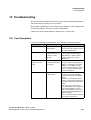
10 Troubleshooting . . . . . . . . . . . . . . . . . . . . . . . . . . . . . . . . . . . . . . . . . . . . . . . . . . . . . . . . . . . . . . . . . . . . 10-1
10.1 Fault Symptoms . . . . . . . . . . . . . . . . . . . . . . . . . . . . . . . . . . . . . . . . . . . . . . . . . . . . . . . . . . . . . . . . . . . 10-1
A31003-M2000-M100-1-76A9, 11/2012
OpenStage WL 3 / WL 3 Plus, Administration Manual
0-5
Contents
For internal use only
10.2 Display Information . . . . . . . . . . . . . . . . . . . . . . . . . . . . . . . . . . . . . . . . . . . . . . . . . . . . . . . . . . . . . . . . . 10-2
10.3 Troubleshooting from the handset Internal Web Administration Page . . . . . . . . . . . . . . . . . . . . . . . . . . 10-5
A Working with Templates . . . . . . . . . . . . . . . . . . . . . . . . . . . . . . . . . . . . . . . . . . . . . . . . . . . . . . . . . . . . . . .
A.1 Create a Template . . . . . . . . . . . . . . . . . . . . . . . . . . . . . . . . . . . . . . . . . . . . . . . . . . . . . . . . . . . . . . . . . . .
A.2 Export a Template . . . . . . . . . . . . . . . . . . . . . . . . . . . . . . . . . . . . . . . . . . . . . . . . . . . . . . . . . . . . . . . . . . .
A.3 Import a Parameter File . . . . . . . . . . . . . . . . . . . . . . . . . . . . . . . . . . . . . . . . . . . . . . . . . . . . . . . . . . . . . . .
A.4 Import a Template . . . . . . . . . . . . . . . . . . . . . . . . . . . . . . . . . . . . . . . . . . . . . . . . . . . . . . . . . . . . . . . . . . .
A-1
A-1
A-1
A-2
A-2
B Configuring OpenStage WL3 Device to be used at OpenScape Voice (OSV) . . . . . . . . . . . . . . . . . . . .
B.1 Prerequisites . . . . . . . . . . . . . . . . . . . . . . . . . . . . . . . . . . . . . . . . . . . . . . . . . . . . . . . . . . . . . . . . . . . . . . .
B.2 WL3 Steps . . . . . . . . . . . . . . . . . . . . . . . . . . . . . . . . . . . . . . . . . . . . . . . . . . . . . . . . . . . . . . . . . . . . . . . . .
B.2.1 Setup TCP Subscriber . . . . . . . . . . . . . . . . . . . . . . . . . . . . . . . . . . . . . . . . . . . . . . . . . . . . . . . . . . . .
B.2.2 Setup TLS Subscriber . . . . . . . . . . . . . . . . . . . . . . . . . . . . . . . . . . . . . . . . . . . . . . . . . . . . . . . . . . . . .
B.2.3 Setup the TLS Subscriber with Root Certificate . . . . . . . . . . . . . . . . . . . . . . . . . . . . . . . . . . . . . . . . .
B.2.4 Setup a Branch Subscriber . . . . . . . . . . . . . . . . . . . . . . . . . . . . . . . . . . . . . . . . . . . . . . . . . . . . . . . . .
B-1
B-1
B-1
B-1
B-2
B-2
B-3
Abbreviations/Glossary
0-6
. . . . . . . . . . . . . . . . . . . . . . . . . . . . . . . . . . . . . . . . . . . . . . . . . . . . . . . . . . . . . . . . C-1
A31003-M2000-M100-1-76A9, 11/2012
OpenStage WL 3 / WL 3 Plus, Administration Manual
Introduction
About this document
1 Introduction
1.1 About this document
Throughout this document you will find cross-references in the text which indicate
further details that can be found in other sections of this document. The crossreferences are colored blue and linked to the relevant place in the document.
Positioning your cursor over the cross-reference text and clicking the left mouse
button will take you to the relevant section.
To return to the original page after viewing a cross-referred page in Adobe
Acrobat or Adobe Reader, click on the “Previous View” arrow (
or
).
This document is intended as a guide when installing the WLAN Handset in a
VoWiFi system. The document describes the settings needed to make the
handset function in a VoWiFi system and is relevant to the following personnel:
•
System Administrator
•
Service Technician
It is recommended that the reader has basic knowledge of the VoWiFi system and
basic knowledge of handset registration in the PBX.
A31003-M2000-M100-1-76A9, 11/2012
OpenStage WL 3 / WL 3 Plus, Administration Manual
1-1
Introduction
Short overview
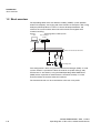
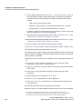
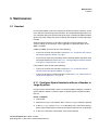
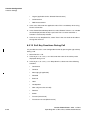
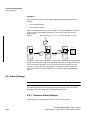
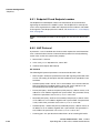
1.2 Short overview
The OpenStage WL3 Voice over Wireless Fidelity (VoWiFi) system provides
wireless IP-telephony, messaging and alarm functions to enterprise LANs. Using
third-party WLAN products as well as in-house developed hardware and
software, the system enables data and voice transmission together with
seamless roaming.
Figure 1
PDM
OpenStage WL3 VoWiFi System
Device Manager
in WSG
Switch to IP Backbone/LAN/Internet
AP
AP
IP-PBX
OpenStage WL3
First configuration is done using the Portable Device Manager (PDM). In small
systems where it is possible to collect all handsets to update settings, daily
maintenance is also done by using the PDM.OpenStage WL3 WSG Server
(WSG) makes it possible to administrate the handsets centrally via a web
interface without the need to collect the handsets.
The handset behavior can be customized to suite each user profile.
1-2
A31003-M2000-M100-1-76A9, 11/2012
OpenStage WL 3 / WL 3 Plus, Administration Manual
Introduction
Functionality matrix
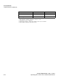
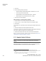
1.3 Functionality matrix
The following matrix shows which functionality that currently can be used by the
different versions and requires settings in the PDM.
WL3
WL3
Messenger
WL3 Plus
Company Phonebook
Yes
Yes
Yes
Central Phonebook
Yes
Yes
Yes
Centralized Management
Yes
Yes
Yes
Customized GUI
Yes
Yes
Yes
Interactive Messaging (IM)
No
Yes
Yes
Location
No
No
Yes
Push to Talk (PTT)
No
No
Yes
Multifunction button
Yes
Yes
No
Push Button Alarm
No
No
Yes
Man-down and No-movement alarm
No
No
Yes
Acoustic Location Signal (ALS)
No
No
Yes
Services
No
No
Yes
Voice Mail
Yes
Yes
Yes
Upload Language
Yes
Yes
Yes
Clear lists in charger
Yes
Yes
Yes
Table 1
The three versions WL3,WL3 Messenger Upgrade and WL3 Plus use the same
hardware and software (except WL3 Plus, which uses a different hardware), and
features are enabled by licensing. The WL3 version is an unlicensed WLAN
Handset with basic functionality, and the WL3 Messenger UpgradeWL3 Plus
versions are licensed WLANHandsets with additional functionalities such as
messaging and alarm, respectively.
A31003-M2000-M100-1-76A9, 11/2012
OpenStage WL 3 / WL 3 Plus, Administration Manual
1-3
Introduction
Functionality matrix
1-4
A31003-M2000-M100-1-76A9, 11/2012
OpenStage WL 3 / WL 3 Plus, Administration Manual
Pre-Installation
VoWiFi System IP addresses
2 Pre-Installation
Before installing handsets in a VoWiFi system, make sure that all equipment is
available. It is recommended to set up chargers and charge the handset batteries
before installation, and to have a number plan available for the handsets. Also be
sure that the IP addressing plan is set up to support the amount of handsets to
be deployed.
We assume that the VoWiFi system is installed including some or all of the
following components (depending on system configuration):
•
DHCP Server. A DHCP server allows devices to request and obtain an IP
address from a server which has a list of addresses available for assignment.
If the WLAN does not have access to a DHCP server, a list of static IP
addresses is necessary.
•
Portable Device Manager. The PDM is used for administration and
programming of the handsets. All settings and updates are in this case done
via the DP1 Desktop Programmer cradle connected over USB.
•
WSG. The WSG handles all communication between the WLAN and its builtin Device Manager. Before installing the handset, make sure the WSG IP
address is available.
For effective administration of a VoWiFi system with several handsets, it is
required to have both a PDM and a Device Manager included in the WSG. In this
case, the PDM is only used to allow the handset to access the WLAN system. All
other settings and updates are done with the Device Manager in the WSG.
2.1 VoWiFi System IP addresses
Complete the table below with the IP addresses, as a help when configuring the
handsets.
Device
IP address/Number/Port
IP-PBX
If used
WSG
Subnet
Required
If used
Mask*
Number plan
NTP Server
If used
N/A
Yes
address**
DNS Server address*
VoIP settings***
Yes
Central Phonebook
If used
Syslog server
If used
Table 1
A31003-M2000-M100-1-76A9, 11/2012
OpenStage WL 3 / WL 3 Plus, Administration Manual
2-1
Pre-Installation
VoWiFi System IP addresses
Device
IP address/Number/Port
TFTP server
Ekahau
RTLS****
Required
If used
If used
DHCP range
Table 1
* Only required if no DHCP is used, that is, static IP is used.
** Depending on system configuration
*** Gatekeeper IP address or SIP proxy IP address used to access the PBX.
****The IP address and port to the location server.
2-2
A31003-M2000-M100-1-76A9, 11/2012
OpenStage WL 3 / WL 3 Plus, Administration Manual
Programming the WLAN Handset
PDM
3 Programming the WLAN Handset
This chapter describes how to configure handsets in three different ways:
•
It is possible to configure the handset by inserting it into a DP1 Desktop
Programmer cradle connected via USB to the PDM.
•
t is possible to configure the handset via over-the-air (OTA) using the Device
Manager in the WSG.
NOTE: This requires that the IP address to the WSG has been configured in
the handset. The IP address is configured using PDM or via the handset’s
Admin menu.
•
It is possible to configure the basic network settings of the handset via its
Admin menu. See Section , “Administration”, on page 1 for more information
about the settings that can be made.
It is recommended to use the Device Manager in WSG to configure handsets in
a large system. The reason is that it enables to install, upgrade and configure a
large amount of handsets simultaneously. Another benefit is that the collection of
the handsets from the user is not needed.
The PDM enables configuration of one handset at the time inserted in the DP1
Desktop Programmer connected via USB to the administrator’s computer.
NOTE: It is recommended to use templates when configuring handsets. By using
a template, the same configuration can easily be applied to many handsets simultaneously.
3.1 PDM
The PDM runs on a PC and is used for configuring the handset as follows:
•
Connect a DP1 Desktop Programmer cradle via USB to the computer running
PDM.
•
Start PDM.
•
Place the handset in this cradle connected to PDM.
For instructions on how to install and use the PDM, see Administration Manual for
Wireless Gateway Server.
A31003-M2000-M100-1-76A9, 11/2012
OpenStage WL 3 / WL 3 Plus, Administration Manual
3-1
Programming the WLAN Handset
WSG
Configuration of handsets via PDM
PDM
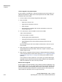
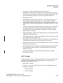
3.2 WSG
WSG runs on an ELISE3 module.
For instructions on how to use the WSG, see Administration Manual for Wireless
Service Gateway.
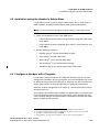
3.2.1 Over-the-Air
There is no external equipment needed besides the Device Manager in WSG and
VoWiFi system. Please proceed with Section , “Installation of WLAN Handsets”,
on page 1.
Figure 1
Configuration of handsets via Over-the-Air (OTA)
VoWiFi
System
IP
Device Manager
in WSG
3-2
AP
Access Point
Client
A31003-M2000-M100-1-76A9, 11/2012
OpenStage WL 3 / WL 3 Plus, Administration Manual
Installation of WLAN Handsets
Installation with Central Device Management (WSG)
4 Installation of WLAN Handsets
This section describes the recommended procedure for installing and configuring
handsets. There are several ways to install a handset, but the procedures
described here guarantees simple maintenance of the network.
It is recommended to use the Device Manager in WSG to install and maintain
handsets in a large network. The reason is that it enables to install, upgrade and
configure a large amount of handsets simultaneously. Another benefit is that the
collection of the handsets from the user is not needed due to configuration is
performed over the air (OTA). The handset must first be configured in the PDM to
access the WSG later on.
The PDM enables administration of one handset at the time inserted in a Desktop
Programmer (DP1) connected via USB to the administrator’s computer.
Installation steps in large VoWiFi Systems using WSG and PDM
NOTE: If the handset to be installed must use certificate to access a WLAN,
follow the instructions in chapter Section 4.2, “Installation without Central Device
Management(WSG)”, on page 5.
These WLAN settings are common network settings for all handsets.
1. Create templates in the Device Manager in WSG; one with network settings
and another with common settings.
2. Create Numbers and apply the templates.
3. Create a template with identical network settings in the PDM.
See Section 4.1, “Installation with Central Device Management (WSG)”, on page
1 for more information.
Installation steps in small VoWiFi Systems using PDM
1. Create Numbers.
2. Create one template for all settings in the PDM.
See Section 4.2, “Installation without Central Device Management(WSG)”, on
page 5 for more information.
4.1 Installation with Central Device Management (WSG)
When installing a large amount of handsets in a VoWiFi system, it is
recommended to have both the WSG and the PDM to make the maintenance and
handling of the system as simple as possible.
A31003-M2000-M100-1-76A9, 11/2012
OpenStage WL 3 / WL 3 Plus, Administration Manual
4-1
Installation of WLAN Handsets
Installation with Central Device Management (WSG)
4.1.1 Create a Network Template in the WSG
Create one template that contains the network parameters (also include the
security settings). Besides the network parameters, additional parameters might
also be set, for example VoIP settings and IP address to WSG. The template must
be created to prevent the WSG from restoring the parameters to default during
the first synchronization.
NOTE: Only select the parameters that are changed, if all parameters are
selected the system performance decreases.
1. Open a web browser and enter the address to the WSG.
2. Click “Device Manager“. You might be prompted to log on the Device
Manager.
3. Select the Templates tab and click “New“. The New template window is opened.
4. In the Device type and Parameter version drop-down lists, select the
corresponding device type and parameter version to use, respectively.
5. In the Name field, enter a descriptive name of the template.
6. Click “OK“.
7. Set the following network parameters:
•
Network settings1 (located under Network > Network A, B, C, or D)
•
VoIP settings2 (located under VoIP)
•
Syslog settings3 (if any) (located under Device > General)
•
WSG settings4 (located under Device > WSG)
8. Click “OK“ to save the template.
NOTE: : See Working with Templates for tip on how to work with templates when
using both PDM and WSG.
1. All required system settings for the WLAN. For example SSID and Security mode.
2. For example VoIP protocol, Gatekeeper IP address or SIP proxy IP address used to access the
PBX.
3. The parameter “Syslog“ must be enabled in order to set the “Syslog IP address“.
4. IP address and password (if any) to the WSG.
4-2
A31003-M2000-M100-1-76A9, 11/2012
OpenStage WL 3 / WL 3 Plus, Administration Manual
Installation of WLAN Handsets
Installation with Central Device Management (WSG)
4.1.2 Create a Common Template in the WSG
Create another template with the common handset settings applicable to all
handsets (exclude the parameters and security settings configured in the
Network template). This template contains for example, hidden menu items in the
display, certain level of ring signal and vibrators.
NOTE: Only select the parameters that are changed, if all parameters are
selected the system performance decreases.
1. Open a web browser and enter the address to the WSG.
2. Click “Device Manager“.
3. Select the Templates tab and click “New“.
4. In the Device Type and Parameter version drop-down lists, select the
corresponding device type and parameter version to use, respectively.
5. In the Name field, enter a descriptive name of the template.
6. Set the specific parameters. See section Section 4.4, “Configure a Handset
with a Template”, on page 7 for more information.
4.1.3 Create Numbers in the WSG
Create a range of Numbers and apply the templates previously created in the
WSG.
NOTE: Do not add numbers already used because these handsets already exist
in the system although not saved in the Device Manager in WSG. The Device
Manager will overwrite the existing parameters in the handset.
NOTE: The parameter version of the template must be equal to or less than the
selected parameter version.
1. Open a web browser and enter the address to the WSG.
2. Click “Device Manager“.
3. Select the Numbers tab and click “New“. The New numbers window is opened.
A31003-M2000-M100-1-76A9, 11/2012
OpenStage WL 3 / WL 3 Plus, Administration Manual
4-3
Installation of WLAN Handsets
Installation with Central Device Management (WSG)
4. In the Device Type and Parameter version drop-down lists, select the device type
and the parameter version to use, respectively.
NOTE: The device type and parameter version must match the handsets to
be used to apply the template.
5. In the Prefix field, enter the numbers’ prefix (if needed).
6. Create a range of numbers by selecting the “Range“ option. Enter the start
call number and the end call number in the fields, respectively. Click “OK”.
NOTE: The maximum range that can be added at a time are 100 numbers.
7. Apply the network settings template to the selected handsets. See Section
4.4.2, “Apply a Template to a Handset with a Number”, on page 8.
8. Apply the common settings template to the selected handsets. See Section
4.4.2, “Apply a Template to a Handset with a Number”, on page 8.
9. Close the WSG.
4.1.4 Create a Network Template with Initial
Configuration in the PDM
In a factory delivered handset, the WLAN settings are not configured that is
required to access the WSG. Using the PDM allows the handset to be primed with
the WLAN parameters and allows it to log in to the Device Manager in WSG for
future management over the air.
Create a template with the basic network settings and IP address to WSG. This
template is only used once for each handset since it must access the WLAN and
then log on the Device Manager. After log in, the settings in the handset are
changed according to the templates in the Device Manager in WSG.
1. Open the PDM.
2. Do one of the following:
•
If a network template was created in the Device Manager in WSG, export
this template and import it to PDM. See Working with Templates for more
information. (Recommended)
•
Create a template (see Section 4.4.1, “Create a template”, on page 8)
with the following network parameters:
- Network settings* (located under Network > Network A (B, C, or D)
- WSG settings** (located under Device > WSG)
4-4
A31003-M2000-M100-1-76A9, 11/2012
OpenStage WL 3 / WL 3 Plus, Administration Manual
Installation of WLAN Handsets
Installation without Central Device Management(WSG)
Note: The parameters in this template should be identical to the parameters in the
network template created in the WSG.
* All required system settings for the WLAN. For example SSID and Security mode.
** IP address and password (if any) to WSG.
3. Put the handset in the Desktop Programmer (DP1) cradle.
4. Run the template. See Section 4.4.3, “Apply a Template to a Handset without
a Number”, on page 9.
5. Remove the handset when synchronization is finished.
6. Enter the Number and the password 1 (if any). Press “Login“.
Settings that were stored for the handset in the Device Manager in WSG will
now be downloaded to the handset. This can, for example, be unique soft- or
hot keys that have been prepared earlier. When the settings have been
downloaded to the handset, it might be restarted depending on the parameter
changes.
7. Repeat step 3 – 6 for all handsets.
4.2 Installation without Central Device Management(WSG)
In a small VoWiFi system, the administration can be handled using only the PDM.
The synchronization is in this case not handled automatically by the system when
a handset’s parameters are changed in the PDM. When the parameters have
been changed in PDM, each handset must be placed in the Desktop Programmer
(DP1) cradle connected to the administrator’s computer in order to synchronize
the parameters with the handset.
1. Open the PDM.
2. In the Numbers tab, click “New“. The New numbers window is opened.
3. In the Device Type and Parameter version drop-down lists, select the matching
device type and the parameter version for the handset to be use, respectively.
4. In the Prefix field, enter the numbers’ prefix (if needed).
5. Create a range of numbers by selecting the “Range“ option. Enter the start
call number and the end call number in the fields, respectively.
6. Click “OK”.
7. Create a network settings template (see Section 4.4.1, “Create a template”,
on page 8) with the following network parameters:
•
Network settings2 (located under Network > Network A, B, C, or D)
1.The password is only required if the “Password“ parameter is set.
A31003-M2000-M100-1-76A9, 11/2012
OpenStage WL 3 / WL 3 Plus, Administration Manual
4-5
Installation of WLAN Handsets
Installation without Central Device Management(WSG)
8. Create another template (see Section 4.4.1, “Create a template”, on page 8)
with the common handset settings applicable to all handsets (exclude the
network parameters and used security settings). Example of parameters
settings:
•
VoIP settings1 (located under VoIP)
•
Software TFTP IP address (if any) (located under Device > General)
•
Syslog settings2 (if any) (located under Device > General)
In addition, settings for hiding menu items in the display, certain level of ring
signal and vibrators etc. can also be configured.
9. Apply the network settings template to the handset, see Section 4.4.2, “Apply
a Template to a Handset with a Number”, on page 8.
10. Apply the common settings template to the handset, see Section 4.4.2, “Apply
a Template to a Handset with a Number”, on page 8.
11. Put the handset in the Desktop Programmer (DP1) cradle.
12. In the Device Wizard window, select “Associate with number“ and press “OK“.
13. Select the handset to associate with. Press “OK“.
The number and parameter settings saved in the PDM will now be synchronized
with the handset. In addition, the handset’s Device ID will also be synchronized
with the number in the PDM.
If certificates must be used to access a VoWiFi system, also perform the steps 14
- 19.
14. In the Numbers tab, right-click the handset’s number and select “Edit
certificates“. An Edit certificate window opens.
15. In the Root tab and Client tab, click “Edit“ and select the certificates to import.
Click “Close“.
16. In the Numbers tab, right-click the handset’s number and select “Edit
parameters“.
17. Select “Network X“ (X represents A, B, C, or D).
18. In the Security mode drop-down list, select “EAP-TLS“.
19. In the EAP client certificate drop-down list, select the client certificate to be
used. Click “OK“.
20. Remove the handset when synchronization is finished.
Repeat the steps 11-13, 20 (if needed, perform the steps 14-19) for all handsets.
2. All required system settings for the WLAN. For example SSID and Security mode.
1. VoIP protocol, Gatekeeper IP address or SIP proxy IP address used to access the PBX.
2. The parameter “Syslog“ must be enabled in order to set the “Syslog IP address“.
4-6
A31003-M2000-M100-1-76A9, 11/2012
OpenStage WL 3 / WL 3 Plus, Administration Manual
Installation of WLAN Handsets
Installation using the Handset’s Admin Menu
4.3 Installation using the Handset’s Admin Menu
It is possible to install a handset using its Admin menu. This is useful when no
PDM or WSG is available and the handset needs to be installed quickly.
NOTE: It is only possible to configure the basic settings via the Admin menu.
1. There are two options to access the Admin menu:
•
If the handset has been factory reset or not been configured; in idle mode,
enter 40022.
•
If the handset has been configured; press “Menu“, select “Settings“ and
enter 40022.
2. Set the following parameters:
•
Network settings1 (located under Network setup)
•
VoIP settings2 (located under VoIP)
•
WL3 settings3 (if any) (located under WL3)
•
Syslog settings4 (if any) (located under Syslog)
•
Add license key (if any) (located under Enter license key)
4.4 Configure a Handset with a Template
It is possible to select a handset in the PDM and directly change one or more
configuration parameters. By using a template, the same configuration can easily
be applied to many handsets simultaneously. Templates are also an efficient way
to give good control over which changes that are applied to each handset.
Templates enables configuration of all aspects of a handset from sound volume
to keypad short cuts.
Your supplier can provide example templates for different PBX:s. The handset will
have full functionality towards the PBX even without such a template. By using
such a template, though, the handset will be customized for that PBX with menu
options for PBX specific functions.
1.
2.
3.
4.
All required system settings for the WLAN. For example SSID and Security mode
VoIP protocol, Gatekeeper IP address or SIP proxy IP address used to access the PBX.
IP address and password (if any) to the WSG.
The parameter “Syslog“ must be enabled in order to set the “Syslog IP address“.
A31003-M2000-M100-1-76A9, 11/2012
OpenStage WL 3 / WL 3 Plus, Administration Manual
4-7
Installation of WLAN Handsets
Configure a Handset with a Template
4.4.1 Create a template
1. Open the PDM or the Device Manager in the WSG.
2. Select the Templates tab and open the menu “Template > New...“. The New
Template window is opened.
3. Select the device type and parameter version that matches the software
version installed on the handset. Give the template a descriptive name.
The parameters that are not part of the template will be left unchanged on the
handset. The parameter version of an installed handset is visible under the
Numbers tab or the Devices tab.
4. Click “OK“.
5. Select the check box of each parameter that you want to be part of this
template and enter the proper value.
6. Click “OK“ to save the template.
4.4.2 Apply a Template to a Handset with a Number
1. Open the PDM or the Device Manager in the WSG.
2. In the Numbers tab, select the handset(s) you want to apply the template to.
NOTE: If several handsets shall be selected, they must be of the same device
type and have the same parameter version.
3. Make a right-click and select “Run template...“.
Only templates with a parameters version matching the selected handsets will be
shown. Select the template you want to apply and click “OK“.
The template is applied. The number of parameters in the template will affect the
time it takes to apply the template to the selected handsets.
When looking at a handset under the Numbers tab, the column “Last run
template“ will show the name of the most recently applied template.
This function cannot be used to download certificates to the handsets.
4-8
A31003-M2000-M100-1-76A9, 11/2012
OpenStage WL 3 / WL 3 Plus, Administration Manual
Installation of WLAN Handsets
Configure a Handset with a Template
4.4.3 Apply a Template to a Handset without a
Number
NOTE: This feature is only applicable for the PDM. However, in the Device
Manager inWSG, it is possible to apply a template to a handset without a number
using the Baseline function. The Baseline function or a template cannot be used
to download certificates to the handsets. See Installation and Operation Manual,
WSG, TDXXXXX.
It is possible to apply a template to a handset without a number in the PDM.
1. Put the handset in the Desktop Programmer (DP1) cradle.
2. In the Found Device Wizard window, select the “Run template“ option.
3. Click “Next >“.
Only templates with a parameter version matching the selected handset will be
shown.
4. Select the template that shall be applied and click “OK“.
The template is applied. The number of parameters in the template will affect the
time it takes to apply the template to the selected handset.
4.4.4 Save Handset Configuration as a Template
It is possible to save all settings of a handset as template. Note that this does not
include contacts, certificates and other personal data. The template will only
contain configuration data.
This template can be used as a backup if you want to restore the configuration of
the handset at a later stage or as a template that can be applied to a number of
handsets.
1. Open PDM or the Device Manager in the WSG.
2. In the Numbers tab, select the handset you want to save as a template.
3. Make a right-click and select “Use as a template...“. Enter a descriptive name
for the template.
4. The Edit template window is opened. By default, all parameters are selected
and are saved when clicking “OK“.
If one or more parameters should be excluded, remove them by clearing the
check box next to the parameter.
A31003-M2000-M100-1-76A9, 11/2012
OpenStage WL 3 / WL 3 Plus, Administration Manual
4-9
Installation of WLAN Handsets
Configure a Handset with a Template
Some parameters are user specific. If it is decided to apply this type of
template to several handsets, it is recommended to exclude the following
parameters:
•
User display text - A text string displayed in idle mode. The parameter is
located directly under “Settings“.
•
Phone lock PIN code - The security code used to unlock the keypad. The
parameter is located under Settings > Locks.
•
Endpoint ID - The identity/name of the user registered in the PBX. The
parameter is located under VoIP > General.
5. Click “OK“.
4.4.5 Synchronizing a Handset with PDM
After installing and saving a handset, it will be synchronized each time it is
connected to the PDM. The synchronization transfers parameter changes
between the handset and the PDM and vice versa as follows:
•
If a parameter has been changed in the handset, it will be transferred to the
PDMWSG.
•
If a parameter has been changed in the PDMWSG while the handset was
disconnected, it will be transferred to the handset.
If the same parameter has been changed in both the PDMWSG and the handset,
the value in PDMWSG will be transferred to the handset.
4.4.6 Configure Handset without Saving It in PDM
It is possible to configure a handset without saving it in the PDM. An unsaved
handset do not have the symbol
in the Saved column. The settings in the
handset can be synchronized and saved in the PDM later on. However, it is
recommended to save the handset in PDM if backup is needed. For example
when a handset needs to be replaced.
1. Put the handset in the Desktop Programmer (DP1) cradle.
2. Open PDM.
3. In the Numbers tab, select the unsaved handset you want to configure.
4. Select Number > Edit parameters.
5. The Edit parameters window is opened. Edit the parameters of the handset and
click “OK“.
4-10
A31003-M2000-M100-1-76A9, 11/2012
OpenStage WL 3 / WL 3 Plus, Administration Manual
Installation of WLAN Handsets
Configure a Handset with a Template
6. Remove the handset from the Desktop Programmer (DP1) cradle. The
handset is no longer visible in the PDM and the settings are only saved in the
handset.
A31003-M2000-M100-1-76A9, 11/2012
OpenStage WL 3 / WL 3 Plus, Administration Manual
4-11
Installation of WLAN Handsets
Configure a Handset with a Template
4-12
A31003-M2000-M100-1-76A9, 11/2012
OpenStage WL 3 / WL 3 Plus, Administration Manual
Maintenance
Handset
5 Maintenance
5.1 Handset
In an existing VoWiFi system it is important to be able to replace handsets, install
new handsets and exchange faulty handsets. The recommended procedure is to
use a template with basic network settings for log in, created in the PDM, and then
get the rest of the settings that were created by the templates in Device Manager
in WSG
Another important matter is to be able to upgrade system parameters and
security settings in the handsets. These upgrades are preferably done in the
WSG if available.
If PDM and WSG are used, do one of the following:
•
If you want to install new handset, see Section 4.1, “Installation with Central
Device Management (WSG)”, on page 1.
•
If you want to create spare handsets to be used when broken handsets need
to be replaced later on, see Section 5.1.1, “Configure Spare Handsets without
a Number in Large Systems”, on page 1.
If only PDM is used, do one of the following:
•
If you want to install new handset, see Section 4.2, “Installation without
Central Device Management(WSG)”, on page 5.
•
If you want to replace a broken handset, see Section 5.2.4, “Replacement of
Handset with PDM Only”, on page 13.
5.1.1 Configure Spare Handsets without a Number in
Large Systems
In large systems where WSG is used, it is recommended to configure a couple of
spare handsets without a number in order to quickly replace a broken handset
later on.
Create a Template
1. Open PDM.
2. Select the Templates tab and click “New“. The New template window is opened.
3. In the Device type and Parameter version drop-down lists, select the matching
device type and parameter version for the spare handset to use, respectively.
4. In the Name field, enter a descriptive name of the template.
A31003-M2000-M100-1-76A9, 11/2012
OpenStage WL 3 / WL 3 Plus, Administration Manual
5-1
Maintenance
Handset
5. Click “OK“.
6. Set the following network parameters:
•
Network settings1 (located under Network > Network A, B, C, or D)
•
VoIP settings2 (located under VoIP)
•
Syslog settings3 (if any) (located under Device > General)
•
WSG settings4 (if any) (located under Device > WSG)
7. Click “OK“ to save the template.
Apply Template to a Handset without a Number
1. Put the handset in the Desktop Programmer (DP1) cradle.
2. In the Found Device Wizard window, select the “Run template“ option.
3. Click “Next >“.
Only templates with a parameter version matching the selected handset will be
shown.
4. Select the template that shall be applied and click “OK“.
The template is applied. The number of parameters in the template will affect the
time it takes to apply the template to the selected handset.
5. Switch off the handset when User name and Password are displayed.
Tip: If the handset shall replace a broken handset, continue with Section 5.2.2,
“Replacement of Handset with WSG”, on page 9.
5.1.2 Upgrade Handset Software
NOTE: Pay attention to the software Release Notes before changing the
software.
The handset software can be upgraded over the air using Centralized Device
Management (WSG) or a TFTP server, or by cable using PDM.
1. All required system settings for the WLAN. For example SSID and Security mode.
2. For example VoIP protocol, Gatekeeper IP address or SIP proxy IP address used to access the
PBX.
3. The parameter “Syslog“ must be enabled in order to set the “Syslog IP address“.
4. IP address and password (if any) to the WSG.
5-2
A31003-M2000-M100-1-76A9, 11/2012
OpenStage WL 3 / WL 3 Plus, Administration Manual
Maintenance
Handset
5.1.3 Upgrade Software OTA via TFTP
Software upgrade OTA via TFTP is used in small VoWifi systems and is
recommended to use if no WSG is available. The benefit is that the handsets do
not need to be collected by the administrator since the software upgrade is
performed over the air.
In order to upgrade the software via TFTP, the following must be done:
1. If needed, the handset must be configured in PDM to access a TFTP server,
seeSection 5.1.3, “Configure Access to the TFTP Server”, on page 3.
Tip: It is recommended to configure the TFTP server’s IP address when
installing the handsets. See Section 4.2, “Installation without Central Device
Management(WSG)”, on page 5.
2. If needed, a new software information file (packageinfo.inf) and a software
(.bin) file must be uploaded to the TFTP server. These files are provided by
your supplier. First rename the .pkg file to .zip and then unzip. Then the
needed .inf and .bin files are available.
See the manual for the TFTP server used for more information on how to
upload files.
3. The handset must be restarted. When the handset has been restarted, it
connects to the TFTP server and downloads the software information file (.inf)
that contains information about the software version. If the software version
differs from the handset’s software version, the handset will download the
software file (.bin) from the TFTP server. The handset will be restarted when
the software upgrade is performed.
Configure Access to the TFTP Server
1. Put the handset in the Desktop Programmer (DP1) cradle.
2. Open the PDM.
3. Open the Numbers tab and select the handset.
4. Make a right-click and click “Edit parameters“.
5. Select Device > General.
6. In the Software TFTP IP address field, enter the IP address to the TFTP server.
7. Click “OK“.
5.1.4 Upgrade Software via PDM
Software upgrade via PDM is used in small VoWiFi systems. The handsets need
to be collected by the administrator due to the software upgrade is performed via
the connected to PDM.
A31003-M2000-M100-1-76A9, 11/2012
OpenStage WL 3 / WL 3 Plus, Administration Manual
5-3
Maintenance
Handset
1. Open the PDM.
2. In the Devices tab, right-click the handset to be upgraded. Select “Upgrade
software...“.
3. In the Available files drop-down list, select the desired software file (.bin).
If needed, import the software file to be used by clicking “Import“. Locate the
software file (.bin or .pkg) and click “Open“.
4. Click “OK“.
5.1.5 Upgrade Software Over the Air (OTA) via
Centralized Device Management (WSG)
Software upgrade via WSG is used in large VoWiFi systems. The benefit is that
the handsets do not need to be collected by the administrator due to the software
upgrade is performed over the air (OTA).
1. Open the Device Manager in the WSG.
2. Open the Devices tab and select the handsets to be upgraded.
3. Make a right-click and click “Upgrade software...”.
4. In the Available software drop-down list, select the desired software file (.bin).
If needed, import the software file to be used by clicking “Import“. Locate the
software file (.bin or .pkg) and click “Open“.
5. In the Upgrade section and Activate new software section, select when the
software shall be upgraded and activated on the handset, respectively.
6. Click “OK“.
Tip: It is also possible to upgrade several handsets of the same device type
simultaneously using the Baseline function in the WSG. See Administration
Manual for Wireless Service Gateway.
5.1.6 Recapture the Earlier Software
The handset stores two software versions which makes it possible to force the
handset to jump back to the earlier software. This feature shall be used if the
current software does not work properly.
NOTE: The handset must be switched off to be able to load the earlier software.
5-4
A31003-M2000-M100-1-76A9, 11/2012
OpenStage WL 3 / WL 3 Plus, Administration Manual
Maintenance
Handset
Press and hold the keys “7” and “8” and press On/Off key at the same time. The
handset loads the earlier software and will keep it as long it is not restarted.
5.1.7 Upgrade Handset Functionality using License
It is possible to upgrade a handset by downloading a license. The following
license is available:
•
WL3 Messenger Upgrade License
There are three alternatives for upgrading a handset:
•
Automatic upgrade, see Section 5.1.7, “Automatic license upgrade”, on page
5.
•
License upgrade using import/export, see Section 5.1.7, “License upgrade
using import/export”, on page 6.
•
Manual upgrade, see Section 5.1.7, “Manual license upgrade”, on page 6.
NOTE: A handset can be re-licensed up to 99 times.
Automatic license upgrade
Use this option if the PDM has an Internet connection to the License Server.
1. Open the PDM.
2. Put the handset in the Desktop Programmer (DP1) cradle.
First time the handset logs on the PDM, the license key will automatically be
downloaded to the handset, go to step 4.
3. If the handset has been logged on to the PDM before, no automatic check for
licenses will be done. The PDM and License Server must be synchronized as
follows;
•
Select the “Licences“ tab.
•
Right-click the handset in the list.
•
Select “Refresh“.
The license key will now be downloaded to the handset.
4. The handset will be restarted. See also Section 5.1.7, “Upgrade Handset
Functionality using License”, on page 5 for viewing the handset’s license
option(s).
If the handset has been updated to a new device type (to WL3 Messenger
Upgrade License), both the new device and the old device is displayed in
PDM. The old device has to be manually removed.
A31003-M2000-M100-1-76A9, 11/2012
OpenStage WL 3 / WL 3 Plus, Administration Manual
5-5
Maintenance
Handset
License upgrade using import/export
Use this option if the PDM has no Internet connection to the License Server. A
product information file (.XML) must first be exported from the PDM, and then
imported to the License Web.
1. Put the handset in the Desktop Programmer (DP1)cradle.
2. Open the PDM.
•
Select the “Licences“ tab.
•
Right-click the handset(s) in the list.
•
Select “Export“.
•
Save the file on a computer with Internet connection to access the
License Web later on.
3. In a web browser, enter the address to the License Web:
“https://www.xxxxxxxxxx“
The License Web is used for:
•
Importing the product information file
•
Viewing/Purchasing the license(s) for the handset(s)
•
Downloading the license file containing the license key(s) for the
handset(s)
See the online help on the License Web for information on how to use the
License Web.
4. When the license file (.XML) containing the license key(s) has been
downloaded from the License Web, select File > Import > Licences in the
PDM to import the file.
5. When the file is imported, the license key(s) is downloaded to the handset(s),
and the handset will be restarted. See also Section 5.1.7, “Upgrade Handset
Functionality using License”, on page 5 for viewing the handset’s license
option(s).
If the handset has been updated to a new device type (to WL3 Messenger
Upgrade License), both the new device and the old device are displayed in
PDM. The old device has to be manually removed.
Manual license upgrade
Use this option if the serial numbers of the handset cannot be exported to a file
due to a PDM is not in use. The serial number(s) must be manually entered in the
License Web to get the corresponding license key for the handset. The license
key must also be manually entered in the handset. See the online help on the
License Web for information on how to get a license key.
5-6
A31003-M2000-M100-1-76A9, 11/2012
OpenStage WL 3 / WL 3 Plus, Administration Manual
Maintenance
Handset
Tip: If several handsets shall be upgraded, it is recommended to use Section
5.1.7, “License upgrade using import/export”, on page 6.
The license key is added via the Admin menu in the handset, see Section 9.1,
“Admin Menu Tree”, on page 1 for information on how to activate the Admin
menu.
Tip: It is also possible to press *#35# in idle mode for quick access to the “Enter
license key“ menu.
1. Press the soft key “Menu“.
2. Select “Calls“.
3. Select “Admin menu“.
4. Select “Enter license key“.
5. Enter license key without blanks.
6. Press “OK“.
If the license key is valid, a dialog window “License key accepted“ is shown. The
handset will now be restarted.
If the handset has been updated to a new device type (to WL3 Messenger
Upgrade License), both the new device and the old device are displayed in PDM.
The old device has to be manually removed.
Move License
It is possible to move a product license (WL3 Messenger Upgrade License) to an
unlicensed handset. Any optional licenses will follow. For example, aWL3
Messenger Upgrade license can be moved from a handset with a broken display
to an unlicensed handset. The broken handsetcan then be sent for repair.
Prerequisites: A PDM that supports the move license function, and a connection
to the license server.
To move a license using the PDM:
1. Put the licensed handset in the desktop programmer.
2. On the Licenses tab, select the handset online.
3. On the License menu, click “Move license...”.
4. In the Move license dialog, select the unlicensed handset and click “OK”.
The handset in the desktop programmer is restarted.
5. Put the unlicensed handset in the desktop programmer.
6. On the Licenses tab, select the handset online.
7. On the License menu, click “Refresh”.
A31003-M2000-M100-1-76A9, 11/2012
OpenStage WL 3 / WL 3 Plus, Administration Manual
5-7
Maintenance
Replacement of Handsets
The handset in the desktop programmer is restarted.
5.1.8 Perform a Factory reset
When a factory reset is done on a handset, all configuration settings will be
restored to default values; PBX subscriptions, contacts, messages, downloaded
language, certificate etc. will be removed. The software and licenseswill be left
intact.
Factory Reset using PDM
1. Open the PDM.
2. Put the handset in the Desktop Programmer (DP1) cradle.
3. In the Device tab, mark the handset to be factory reset. Note that the handset
must be online.
4. In the Device menu, select “Factory reset“. Alternatively, right-click the
handset and select “Factory reset“.
5. A Reset devices window appears, click “Yes“. The handset will be restarted.
Factory Reset using Handset
It is possible to factory reset a handset from its Admin menu.
1. To activate the Admin menu, select Menu > Settings and enter 40022.
2. Select “Factory Reset“.
3. A Reset portable? window appears, press “Yes“. The handset will be restarted.
5.2 Replacement of Handsets
A handset can be replaced with a spare handset if it is broken. The handset
registered in PDM or WSG, is associated with its device type, device ID and
extension. During the replacement procedure, the broken handset’s device type
and extension will be associated with the spare handset’s device ID.
5.2.1 Replacement Procedure Choice
•
5-8
If you have WSG and already have applied the network template to the spare
handset(s) to log on it later on, see Section 5.2.2, “Replacement of Handset
with WSG”, on page 9.
A31003-M2000-M100-1-76A9, 11/2012
OpenStage WL 3 / WL 3 Plus, Administration Manual
Maintenance
Replacement of Handsets
•
If you have both PDM and WSG, and need to apply the network template to
the spare handset(s) to log on it later on, see Section 5.2.3, “Replacement of
the Handset with PDM and WSG”, on page 11.
•
If you only have PDM, see Section 5.2.4, “Replacement of Handset with PDM
Only”, on page 13.
Data included in a replacement transfer
The following data is replaced during a replacement:
•
User parameters
•
Contacts (entered by the user)
Note that the following data is not replaced:
•
Call list
•
Messages
•
Company phonebook
•
Downloaded language
•
Certificates
•
Licenses1
5.2.2 Replacement of Handset with WSG
There are two different replacement procedures as follows:
•
If the broken handset and the spare handset have the same device type and
functionality license, seeSection 5.2.2, “Replace without Move Licenses in
WSG”, on page 9.
•
If the broken handset and the spare handset have not the same device type
and/or functionality license. The license must be moved to the spare handset,
see Section 5.2.2, “Replace and Move Licenses in WSG”, on page 10.
Replace without Move Licenses in WSG
Both the broken handset and the spare handset must be of the same device type
and have same functionality license.
1. In both handsets, press *#34# in idle mode and select “License“ to check that
they have same device type and licenses.
If the login screen is displayed in the spare handset, press “Info“ and select
“License“.
1. A handset’s license(s) can be moved to an unlicensed handset (WSG) if following the replacement instructions in Section 5.2.2, “Replace and Move Licenses in WSG”, on page 10.
A31003-M2000-M100-1-76A9, 11/2012
OpenStage WL 3 / WL 3 Plus, Administration Manual
5-9
Maintenance
Replacement of Handsets
2. If the broken handset is online in the Device Manager, switch off the handset
to make it offline.
3. Take a spare handset prepared with the network settings (including the IPaddress to the WSG).
4. Enter the Number and leave the password blank. Press “Login“.
The spare handset is automatically updated from the WSG and might be
restarted depending on the changed settings. The last stored settings for the
broken handset in the WSG has been transferred to the spare handset.
Replace and Move Licenses in WSG
The broken handset and the spare handset do not have the same device type
and/or have the same functionality license.
In order to move the licenses to the spare handset, it must be an unlicensed WL3.
To check that the handset is unlicensed, press *#34# in idle mode and select
“License“. Only WL3 must be displayed here.
1. Make sure that the broken handset is saved in the Device Manager (indicated
by a
in the Saved column. If not, in the Numbers tab, right-click the broken
handset and select “Save“.
2. Switch off the broken handset to make it offline in the Device Manager.
3. Take an unlicensed spare handset (WL3) prepared with the network settings
(including the IP-address to the WSG).
4. Enter the number and leave the password blank. Press “Login”. The handset
is now online in the Device Manager.
5. Make sure that the spare handset is saved in the Device Manager (indicated
by a
in the Saved column. If not, in the Numbers tab, right-click the spare
handset and select “Save“.
6. Switch off the spare handset to make it offline in the Device Manager.
7. Switch on the broken handset to make it online in the Device Manager.
8. In the Device Manager, select the “Licenses“ tab.
9. Right-click the broken handset and select “Move license...“.
10. In the Move license window, select the WL3 that should receive the license.
Press “OK“.
11. The broken handset restarts and has now become a WL3. Switch off the
broken handset to make it offline in the Device Manager.
12. Switch on the spare handset to make it online in the Device Manager.
13. In the Device Manager, select the “Licenses“ tab. Right-click the spare
handset and select “Refresh“.
5-10
A31003-M2000-M100-1-76A9, 11/2012
OpenStage WL 3 / WL 3 Plus, Administration Manual
Maintenance
Replacement of Handsets
The spare handset is automatically updated from the WSG and restarted. The
last stored settings and licenses for the broken handset in the WSG has been
transferred to the spare handset.
5.2.3 Replacement of the Handset with PDM and WSG
If the spare handset to be used must be factory reset or no network template has
been applied, a PDM is needed to apply the network template to the spare
handset. When the network template is added, the handset can log on to the
Device Manager.
There are two different replacement procedures as follows:
•
If the broken handset and the spare handset have the same device type and
functionality license, seeSection 5.2.3, “Replace without Move Licenses
using PDM and WSG”, on page 11.
•
If the broken handset and the spare handset have not the same device type
and/or functionality license. The license must be moved to the spare handset,
see Section 5.2.3, “Replace and Move License using PDM and WSG”, on
page 12.
Replace without Move Licenses using PDM and WSG
Both the broken handset and the spare handset must be of the same device type
and have same functionality license.
1. In the handset, press *#34# in idle mode and select “License“ to check that
both handsets have same device type and licenses.
2. Make sure that the broken handset is saved in the Device Manager (indicated
by a
in the Saved column. If not, in the Numbers tab, right-click the broken
handset and select “Save“.
3. Switch off the broken handset to make it offline.
If the spare handset is not prepared with the basic network settings, also perform
the steps 4 - 7.
4. Open the PDM.
5. Put the spare handset in the Desktop Programmer (DP1) cradle.
6. Run the template with the basic network settings containing (see Section 4.4,
“Configure a Handset with a Template”, on page 7):
•
Network settings1 (located under Network > Network A, B, C, or D)
•
VoIP settings2 (located under VoIP)
1. All required system settings for the WLAN. For example SSID and Security mode.
2. VoIP protocol, Gatekeeper IP address or SIP Proxy IP address used to access the PBX.
A31003-M2000-M100-1-76A9, 11/2012
OpenStage WL 3 / WL 3 Plus, Administration Manual
5-11
Maintenance
Replacement of Handsets
•
WSG settings1 (located under Device > WSG)
7. Remove the handset from the Desktop Programmer (DP1) cradle. The
handset might be restarted depending on parameter changes.
8. Enter the number and the password2 (if any). Press “Login”.
The spare handset is automatically updated from the WSG and might be
restarted depending on the parameter changes. The last stored settings for the
broken handset in the WSG has been transferred to the new handset.
Replace and Move License using PDM and WSG
The broken handset and the spare handset do not have the same device type
and/or have the same functionality license.
In order to move the licenses to the spare handset, it must be an unlicensed WL3.
To check that the handset is unlicensed, press *#34# in idle mode and select
“License“. Only WL3 must be displayed here.
1. Make sure that the broken handset is saved in the Device Manager (indicated
by a
in the Saved column. If not, in the Numbers tab, right-click the broken
handset and select “Save“.
2. Switch off the broken handset to make it offline.
3. Open the PDM.
4. Put the unlicensed spare handset (WL3) in the Desktop Programmer (DP1)
cradle.
5. Run the template with the basic network settings containing (see Section 4.4,
“Configure a Handset with a Template”, on page 7):
•
Network settings1 (located under Network > Network A, B, C, or D)
•
VoIP settings2 (located under VoIP)
•
WSG settings3 (located under Device > WSG)
6. Remove the handset from the Desktop Programmer (DP1) cradle. The
handset is restarted.
7. Enter the number and the password3 (if any). Press “Login”.
8. Make sure that the spare handset is saved in the Device Manager (indicated
by a
in the Saved column. If not, in the Numbers tab, right-click the spare
handset and select “Save“.
9. Switch off the spare handset to make it offline.
10. Switch on the broken handset to make it online.
1. IP address and password (if any) to the WSG.
2. The password is only required if the “Password“ parameter is set.
5-12
A31003-M2000-M100-1-76A9, 11/2012
OpenStage WL 3 / WL 3 Plus, Administration Manual
Maintenance
Replacement of Handsets
11. In the Device Manager, select the “Licenses“ tab.
12. Right-click the broken handset and select “Move license...“.
13. In the Move license window, select the WL3 that should receive the license.
Press “OK“.
14. The broken handset restarts and has now become a WL3. Switch off the
broken handset to make it offline in the Device Manager.
15. Switch on the spare handset to make it online in the Device Manager.
16. In the Device Manager, select the “Licenses“ tab. Right-click the spare
handset and select “Refresh“.
The spare handset is automatically updated from the WSGand restarted. The last
stored settings and licenses for the broken handset in the WSG has been
transferred to the spare handset.
5.2.4 Replacement of Handset with PDM Only
Replacement via PDM is used in small VoWiFi systems or when WSG is not
available.
•
If the broken handset and the spare handset have the same device type and
functionality license, seeSection 5.2.4, “Replace without Move Licenses
using PDM”, on page 13.
•
If the broken handset and the spare handset have not the same device type
and/or functionality license. The license must be moved to the spare handset,
see Section 5.2.4, “Replace and Move Licenses using PDM”, on page 14.
Replace without Move Licenses using PDM
Both the broken handset and the spare handset must be of the same device type
and have same functionality license.
1. In both handset, press *#34# in idle mode and select “License“ to check that
they have same device type and licenses.
Alternatively, if the spare handset has been factory reset, press “Info“ and
select “License“.
2. Put the broken handset in the Desktop Programmer (DP1) cradle.
3. Open the PDM.
4. Make sure that the handset is saved in the PDM. In the Numbers tab, a saved
handset has the symbol
in the Saved column. If not, right-click the handset
and select “Save“ in order to transfer the settings to the spare handset later
on.
A31003-M2000-M100-1-76A9, 11/2012
OpenStage WL 3 / WL 3 Plus, Administration Manual
5-13
Maintenance
Replacement of Handsets
5. If the spare handset has been previously used, perform a factory reset, see
Section 5.1.8, “Perform a Factory reset”, on page 8.
6. Put the spare handset in the Desktop Programmer (DP1) cradle.
7. A Found Device Wizard window appears. Select “Associate with Number“ and
click “Next >“.
8. In the list, select the broken handset to be replaced with the spare handset.
Click “OK“.
The broken handset has been replaced and its settings have been transferred to
the spare handset.
Replace and Move Licenses using PDM
The broken handset and the spare handset do not have the same device type
and/or have the same functionality license.
In order to move the licenses to the spare handset, it must be an unlicensed WL3.
To check that the handset is unlicensed, press *#34# in idle mode and select
“License“. Only WL3 must be displayed here.
1. Put the broken handset in the Desktop Programmer (DP1) cradle.
2. Open the PDM.
3. Make sure that the broken handset is saved in the PDM. In the Numbers tab,
a saved handset has the symbol
in the Saved column. If not, right-click the
handset and select “Save“ in order to transfer the settings to the spare
handset later on.
1. Put an unlicensed spare handset () in the Desktop Programmer (DP1) cradle.
2. Run the template with the basic network settings containing (see Section 4.4,
“Configure a Handset with a Template”, on page 7):
•
Network settings1 (located under Network > Network A, B, C, or D)
•
VoIP settings2 (located under VoIP)
The handset might be restarted depending on parameter changes.
3. Put the broken handset in the Desktop Programmer (DP1) cradle.
4. In the PDM, select the “Licenses“ tab.
5. Right-click the broken handset and select “Move license...“.
6. In the Move license window, select the WL3 that should receive the license.
Press “OK“. The broken handset restarts and has now become a WL3.
7. Put the spare handset in the Desktop Programmer (DP1) cradle.
1. All required system settings for the WLAN. For example SSID and Security mode.
2. VoIP protocol, Gatekeeper IP address or SIP Proxy IP address used to access the PBX.
5-14
A31003-M2000-M100-1-76A9, 11/2012
OpenStage WL 3 / WL 3 Plus, Administration Manual
Maintenance
Change Number of a Handset
8. In the PDM, select the “Licenses“ tab. Right-click the spare handset and
select “Refresh“.
The spare handset is restarted and the licenses for the broken handset in the
PDM has been transferred to the spare handset.
9. A Found Device Wizard window appears. Select “Associate with Number“ and
click “Next >“.
10. In the list, select the broken handset to be replaced with the spare handset.
Click “OK“.
The spare handset might be restarted and the settings for the broken handset
in the PDM has been transferred to the spare handset.
5.3 Change Number of a Handset
It is possible to change the number of a handset, but keep all other settings in the
handset.
1. Open PDMor the Device ManagerWSG.
2. Open the Numbers tab, and select the handset to be updated with a new
number.
3. In the Number menu, select “Rename...“. Alternatively, right-click the handset
and select “Rename...” from the menu that appears.
4. In the New prefix field, enter the new prefix (if needed).
5. In the New number field, enter the new number.
NOTE: Make sure that the new number does not exist in another system. If
several handsets have the same number, their settings will overwrite each other
when synchronizing with WSG/PDM.
6. Click “OK“.
The new number will be synchronized with the handset when it is connected to
PDM or WSG.
A31003-M2000-M100-1-76A9, 11/2012
OpenStage WL 3 / WL 3 Plus, Administration Manual
5-15
Maintenance
Update Parameters via WSG
5.4 Update Parameters via WSG
This section describes the general procedure on how to change/update
parameters using the WSG. The update starts when the handset is idle and will
not interrupt an ongoing call.
NOTE: Only select the parameters that are changed, if all parameters are
selected, the system performance decreases.
1. Open the WSG.
2. Create a new template with only the parameters that shall be changed.
3. Select the numbers that should be updated and apply the template.
The handsets are automatically updated from the WSGand might be
restarted depending of which parameters that are changed.
5.5 Perform a Security Upgrade via WSG
This section describes how to perform an update/change of the WLAN password/
authentication using the WSG.
NOTE: Change settings in the handset before change settings in the AP. Else,
synchronization of new settings to the handset settings cannot be performed.
Tip: Leave one access point with the old configuration to allow switched off
handsets to receive the updates when they are turned on. Bring the handset to
that APs coverage area.
1. Open the WSG.
2. Create a new template with the new security settings.
•
Security mode1
3. Apply the new template to the handsets.
The handsets are automatically updated from the WSG and restarted.
NOTE: At this time, the handsets have no access to the WLAN system.
4. Change the security settings for the access points.
1. All required settings for the WLAN. For example User name, Password, Regulatory domain etc.
5-16
A31003-M2000-M100-1-76A9, 11/2012
OpenStage WL 3 / WL 3 Plus, Administration Manual
Maintenance
Upgrade the Template
The handsets are now able to access the WLAN.
5.6 Upgrade the Template
The upgrade procedure of the templates definition version is described in the
Administration Manual for the Portable Device Manager.
5.7 Create a Configuration Backup
It is recommended to have a backup of the configuration in the handsets and the
site.
The backup procedure is described in the Administration Manual for the Wireless
Service Gateway.
A31003-M2000-M100-1-76A9, 11/2012
OpenStage WL 3 / WL 3 Plus, Administration Manual
5-17
Maintenance
Create a Configuration Backup
5-18
A31003-M2000-M100-1-76A9, 11/2012
OpenStage WL 3 / WL 3 Plus, Administration Manual
Handset Configuration
Select Network
6 Handset Configuration
NOTE: This chapter describes settings in parameter definition files (.def). These
files are regularly updated and settings may change slightly. For example "On" to
"Enable" or a parameter can be moved to another directory.
The handset requires some settings to function in the VoWiFi system. All settings
are done in the PDMWSG. This section describes the available settings for the
handset. The first part explains network settings and the second handset settings.
For more information, see the PDM Online Help that is accessible for each
parameter by clicking the icon
in the Edit parameters view, or the
Administration Manual for the Personal Device Manager.
NOTE: Configuring OpenStage WL3 Device to be used at OpenScape Voice
(OSV) see Appendix B in this Manual.
6.1 Select Network
The handset can switch between four different WLAN system configurations
called Network A, Network B, Network C, and Network D. The name can be
changed (via PDM or WSG) and is visible in the handset, see Section 6.1.2,
“Change Name of Network”, on page 2.
A handset can be configured for up to four different WLANs but only for oneWSG
and one VoIP System.
The configured networks in PDM must have a SSID value in order to view them
in the handset.
Network A is the default system and used throughout this manual.
1. Select Network > General.
2. In the Active network drop-down list, select “Network A”.
6.1.1 Change Active Network
1. Select Network > General.
2. In the Active network drop-down list, select “Network A“, “Network B“,
“Network C“, or “Network D“.
A31003-M2000-M100-1-76A9, 11/2012
OpenStage WL 3 / WL 3 Plus, Administration Manual
6-1
Handset Configuration
IP Address Settings
6.1.2 Change Name of Network
The name is shown when selecting network in the handset.
1. Select Network > Network A (or B, C, or D).
2. In the Network name field, enter the name of the network.
6.1.3 Enable Switch between Networks
The handset may be configured to switch between networks on the site.
1. Find parameter Network > General > Auto-switch network, and select
“Enable”.
Parameter Auto-switch network time-out appears. This parameter defines the
time before the handset tries to connect with the next included network.
2. Enter a value in seconds for parameter Auto-switch network time-out.
3. For the networks that should be included in the auto-switch network:
Find parameter Network > Network A (B, C, D) > Include in auto-switch
network, and select “Yes” to enable switch to Network A (B, C, D).
6.2 IP Address Settings
The IP address settings can be configured in two ways.
•
The handset can configured to receive an IP address automatically from a
DHCP server, see Section 6.2.1, “Automatic IP Address Settings”, on page 2.
•
If no DHCP server is used, a unique IP address must be entered manually for
each handset, see Section 6.2.2, “Static IP Address (Manual) Settings”, on
page 3.
6.2.1 Automatic IP Address Settings
1. Select Network > Network A (or B, C, D).
2. In the DHCP mode drop-down list, select “Enable”.
The Phone IP address, Subnet mask and Default gateway are automatically set
up.
6-2
A31003-M2000-M100-1-76A9, 11/2012
OpenStage WL 3 / WL 3 Plus, Administration Manual
Handset Configuration
Network Settings
6.2.2 Static IP Address (Manual) Settings
1. Select Network > Network A (or B, C, D).
2. In the DHCP mode drop-down list, select “Disable (static mode)”. Additional
parameters will be displayed.
3. In the Phone IP address field, enter the unique IP address for the handset.
4. In the Subnet mask field, enter the subnet mask.
5. In the Default gateway field, enter the IP address for the default gateway.
DNS Server Settings
It is possible to configure which DNS server the handset shall use. If the primary
DNS server is available, it is always used. Otherwise, the secondary DNS server
will be used.
NOTE: The DNS parameters are only visible if the DHCP mode is set to “Disable
(static mode)”, see Section 6.2.2, “Static IP Address (Manual) Settings”, on page
3.
Primary DNS Server
1. Select Network > Network A (B, C, or D).
2. In the Primary DNS field, enter the IP address to the primary DNS server.
Secondary DNS Server
1. Select Network > Network A (B, C, or D).
2. In the Secondary DNS field, enter the IP address to the secondary DNS
server.
6.3 Network Settings
6.3.1 SSID
The SSID is the name of the network the handset associates to.
1. Select Network > Network A (B, C, or D).
2. In the SSID field, enter system SSID.
Note that the SSID is case-sensitive.
A31003-M2000-M100-1-76A9, 11/2012
OpenStage WL 3 / WL 3 Plus, Administration Manual
6-3
Handset Configuration
Network Settings
6.3.2 Voice Power Save Mode
The voice power save mode is used during calls. NONE is recommended to
obtain optimal voice quality. U-APSD uses less power but is more sensitive to
network disturbances.
If supported by the infrastructure U-APSD is the preferred choice and multiple the
talk time more than 4 times compared to NONE mode.
1. Select Network > Network A (B, C, or D).
2. In the Voice power save mode drop-down list, select one of following:
•
NONE
•
U-APSD
6.3.3 World Mode Regulatory Domain
There is a set of regional rules for the world mode settings and the a-band that
the handset complies to. The preferred and the default setting is “World mode
(802.11d)”. The handset gets its regulatory settings from the AP. If this is not
supported by the AP, then this has to be set in the handset as follows:
1. Select Network > Network A (B, C, or D).
2. In the World mode regulatory domain drop-down list, select one of the following:
•
World mode (802.11d) (default)
•
ETSI
•
Japan
•
USA
6.3.4 Radio and Channel Selection
The handset supports the 802.11a/n radio and 802.11b/g/n radio, but it cannot
use the 802.11a/n radio and the 802.11b/g/n radio simultaneously. The radio
determines which channels that can be used.
802.11 a/n Channels
Defines which 802.11a/n channels to use. It is recommended to use the value
“UNII-1“. Select “Advanced“ only if the channels shall be set in the Advanced:
802.11 channels parameter, see Section 6.3.4, “Advanced: 802.11 Channels”, on
page 6.
6-4
A31003-M2000-M100-1-76A9, 11/2012
OpenStage WL 3 / WL 3 Plus, Administration Manual
Handset Configuration
Network Settings
1. Select Network > Network A (B, C, or D).
2. In the 802.11 protocol drop-down list, select “802.11a/n“.
3. In the 802.11a/n channels drop-down list, select one of the following:
NOTE: The selected World Mode Regulatory Domain determines which
channels to be used. SeeSection 6.3.4, “Bands and Channels used by WiFi
a-radio”, on page 5.
•
All
•
Non DFS
•
UNII-1
•
UNII-3
•
UNII-1, UNII-2
•
UNII-1, UNII-2, UNII-3
•
UNII-1, UNII-2, UNII-2 Extended
•
Advanced
Bands and Channels used by WiFi a-radio
Frequency band
Channels
Non DFS
5.150 - 5.250 MHz, 36,40,44,48
5.725 - 5.845 MHz 149,153,157,161, 165
UNII-1
5.150 - 5.250 MHz 36,40,44,48
UNII-2
5.250 - 5.350 MHz 52,56,60,64
UNII-2
Extended
5.470 - 5.725 MHz 100, 104, 108, 112,116, 120, 124, 128, 132,
126, 140
UNII-3
5.825 - 5.835 MHz 149,153,157,161
Table 1
802.11 b/g/n Channels
Defines which 802.11b/g/n channels to use. It is recommended to use the default
value “1,6,11“. If set to “All”, all channels are scanned for access points which
decreases the WLAN performance. Select “Advanced“ only if the channels shall
be set in the parameter Advanced: 802.11 channels.
1. Select Network > Network A (B, C, or D).
2. In the 802.11 protocol drop-down list, select “802.11b/g/n“.
3. In the 802.11b/g/n channels drop-down list, select one of the following:
A31003-M2000-M100-1-76A9, 11/2012
OpenStage WL 3 / WL 3 Plus, Administration Manual
6-5
Handset Configuration
Network Settings
•
All
•
1,6,11
•
Advanced
Advanced: 802.11 Channels
Defines which 802.11 channels to use. Only used if the parameter in the 802.11b/
g/n channels, or 802.11a/n channels is set to “Advanced“.
NOTE: It is not possible to scan channels in 802.11b/g/n and 802.11a/n simultaneously.
1. Select Network > Network A (B, C, or D).
2. Enter channels to scan in a comma-separated list, for example 1,6,11 (the
order has no impact; 11,6,1 will give the same result).
6.3.5 Transmission Power
This is the transmission power the handset will use when transmitting data to the
WLAN system. If “Automatic” (default) is used, the transmission power is adapted
according to 802.11h, CCX or maximum possible.
1. Select Network > Network A (B, C, or D).
2. In the Transmission power drop-down list, select one of the following:
•
Automatic
•
0 dBm
•
5 dBm
•
11 dBm
•
14 dBm
•
20 dBm (max)
6.3.6 IP DSCP for Voice/Signaling
Differentiated Services Code Point (DSCP) defines which value to use for
outgoing voice and signaling traffic. The DSCP value is used for QoS on the LAN.
The settings in the handset must agree with the settings in the system, otherwise
it will result in bad voice quality.
6-6
A31003-M2000-M100-1-76A9, 11/2012
OpenStage WL 3 / WL 3 Plus, Administration Manual
Handset Configuration
Security Settings
1. Select Network > Network A (B, C, or D).
2. In the IP DSCP for voice and/or IP DSCP for signaling drop-down list, select
one of the following:
•
0x38 (56) - Class selector 7
•
0x30 (48) - Class selector 6
•
0x2E (46) - Expedited Forwarding (default for voice)
•
0x28 (40) - Class selector 5
•
0x20 (32) - Class selector 4
•
0x1A (26) - Assured forwarding 31 (default for signaling)
•
0x18 (24) - Class selector 3
•
0x10 (16) - Class selector 2
•
0x08 (8) - Class selector 1
•
0x00 (0) - Default
6.4 Security Settings
The WLAN system can be configured to use various encryption and/or
authentication schemes. The use of extensive encryption/authentication
schemes can cause incidents of dropped speech during handover due to the time
to process the authentication.
6.4.1 Open
Select Open if no encryption/authentication is required. To select Open as the
security mode, do the following:
1. Select Network > Network A (B, C, or D).
2. In the Security mode drop-down list, select “Open”.
6.4.2 WEP 64/128-bit Key
To select WEP64/128-bit Key as the security mode. Do the following:
1. Select Network > Network A (B, C, or D).
2. In the Security mode drop-down list, select “WEP64/128-bit Key”. Additional
parameters can now be set. See below.
A31003-M2000-M100-1-76A9, 11/2012
OpenStage WL 3 / WL 3 Plus, Administration Manual
6-7
Handset Configuration
Security Settings
3. In the WEP key 1 field, enter the WEP key to be used.
4. In the WEP transmit key drop-down list, select “WEP key 1“.
6.4.3 WPA-PSK & WPA2-PSK
To select WPA-PSK & WPA2-PSK as the security mode. Do the following:
1. Select Network > Network A (B, C, or D).
2. In the Security mode drop-down list, select “WPA-PSK & WPA2-PSK”.
3. In the WPA-PSK passphrase field, enter the passphrase for WPA-PSK/&
WPA2-PSK.
6.4.4 802.1X with EAP-FAST
To select EAP-FAST as the authentication method. Do the following:
1. Select Network > Network A (B, C, or D).
2. In the Security mode drop-down list., select “EAP-FAST”.
3. In the EAP authentication user name field, enter the user name for EAP
authentication.
4. In the EAP authentication password field, enter the password for EAP
authentication.
6.4.5 802.1X with PEAP-MSCHAPv2
Select PEAP-MSCHAPv2 if root certificate is to be used for authentication. To
select PEAP-MSCHAPv2 as the authentication method. Do the following:
1. Ensure that the handset is online in PDM.
2. Import the root certificate by do the following:
•
In the Numbers tab, right-click the handset’s number and select “Edit
certificates“. An Edit certificate window opens.
•
In the Root tab, click “Edit“ and select the root certificates to import. Click
“Close“.
3. Select Network > Network A (B, C, or D)
4. In the Security mode drop-down list, select “PEAP-MSCHAPv2”.
6-8
A31003-M2000-M100-1-76A9, 11/2012
OpenStage WL 3 / WL 3 Plus, Administration Manual
Handset Configuration
Handset Settings
5. In the EAP authentication user name field, enter the user name for EAP
authentication.
6. In the EAP authentication password field, enter the password for EAP
authentication.
6.4.6 EAP-TLS
Select EAP-TLS if a client certificate is to be used for authentication. To select
EAP-TLS as the authentication method, do the following:
1. Ensure that the handset is online in PDM.
2. Import the certificate by do the following:
•
In the Numbers tab, right-click the handset’s number and select “Edit
certificates“. An Edit certificate window opens.
•
In the Root tab and Client tab, click “Edit“ and select the certificates to
import. Click “Close“.
3. Select Network > Network A (B, C, or D).
4. In the Security mode drop-down list, select “EAP-TLS”.
5. In the EAP client certificate drop-down list, select the client certificate to use.
6.5 Handset Settings
This section describes specific settings for the handset that can be changed using
the keypad on the handset, and/or can be set in the PDM/WSG to assist the user
or to set the initial value when the handset is commissioned.
General Settings
Keypad*
PDM
Section 6.5.1, “Automatic key lock”, on page 10
x
x
Section 6.5.2, “Phone lock”, on page 11
x
x
Section 6.5.4, “Headset type”, on page 12
x
x
Section 6.5.3, “Audio adjustment”, on page 11
x**
x
Section 6.5.12, “Short cuts”, on page 16
x
x
Section 6.5.6, “Configure Profiles”, on page 13
x
x
Section 6.5.8, “Battery Warning”, on page 15
x
x
Section 6.5.5, “In Charger Behavior”, on page 13
x**
x
Section 6.5.9, “Shared Phone”, on page 15
x
Telephony
Section 6.9.8, “Message Centre Number”, on page 33
x
Table 2
A31003-M2000-M100-1-76A9, 11/2012
OpenStage WL 3 / WL 3 Plus, Administration Manual
6-9
Handset Configuration
Handset Settings
Section 6.9.9, “Max number of Call Completions”, on page 33
x
Section 6.9.10, “Dial Pause Time”, on page 33
x
Section 6.9.11, “Direct off Hook from Charger”, on page 33
x
x
Section 6.9.12, “Replace Call Rejected with User Busy”, on page
34
x
Section 6.9.6, “Emergency Number”, on page 32
x
Section 6.5.14, “Import Contacts”, on page 19
x
Section 6.5.15, “Company Phonebook”, on page 19
x
Section 6.5.16, “Central Phonebook”, on page 20
x
Section 6.9.7, “Voice Mail Number”, on page 32
x
Regional Settings
Section 6.10.1, “Set Time & Date”, on page 34
x
x
Section 6.5.11, “Select Default Language”, on page 16
x
x
Section 6.10.3, “Dialing Tone Pattern”, on page 35
x
Customize Menu
Section 6.5.10, “Uploadable Language”, on page 16
x
Section 6.12.1, “Hide Menu Items”, on page 37
x
Section 6.12.2, “Services”, on page 37
x
x
Section 6.11.1, “User Display Text”, on page 35
x
x
Section 6.11.3, “Font style”, on page 36
x
x
Display
Section 6.11.4, “Backlight Timeout”, on page 36
x
Section 6.11.5, “Brightness”, on page 36
x
x
Section 6.11.6, “Screen Saver”, on page 36
x
x
x**
x
Messaging
Section 6.7, “Messaging Settings”, on page 20
Alarm
Section 6.8, “Alarm Settings”, on page 26
x
Table 2
*
Refer to the User Manual for more information on how the user can change the settings via the
handset’s keypad
** Some parameters cannot be changed via the keypad.
6.5.1 Automatic key lock
1. If configured, it is possible to dial a pre-defined emergency number when the
keypad is locked, see Section 6.9.6, “Emergency Number”, on page
32.Select Device > Settings.
2. In the Automatic key lock drop-down list, select one of the following:
6-10
A31003-M2000-M100-1-76A9, 11/2012
OpenStage WL 3 / WL 3 Plus, Administration Manual
Handset Configuration
Handset Settings
•
Enable - activates automatic key lock.
•
Disable - deactivates automatic key lock
6.5.2 Phone lock
Activate the phone lock to prevent unauthorized usage of the handset. A
password is required to unlock the handset in order to access its functions.
NOTE: If configured, it is possible to dial a pre-defined emergency number when
the handset is locked, see Section 6.9.6, “Emergency Number”, on page 32. It is
not recommended to use Phone Lock when using the Shared Phone feature, see
Section 6.5.9, “Shared Phone”, on page 15
1. Select Device > Settings.
2. In the Phone lock drop-down list, select one of the following:
•
On - the handset will be locked after a few seconds when it is not used.
•
On in charger - the handset will be locked when placed in charger.
•
Off - the phone lock is disabled.
6.5.3 Audio adjustment
Select the volumes for the different audio signals in the handset.
1. Select Audio > Volume.
2. Select the applicable volumes item in the drop-down lists:
•
Handsfree volume
•
Headset volume
•
Speaker volume
3. In the Persistent volume drop-down list, select “Enable” to automatically store
volume changes in the handset for future calls.
The parameter affects the “Normal”, “Headset“, “Loudspeaking“ mode.
For selection of headset, see Section 6.5.4, “Headset type”, on page 12.
NOTE: Changing this parameter may result in lower sound quality and high
sound level. Evaluate carefully before applying.
A31003-M2000-M100-1-76A9, 11/2012
OpenStage WL 3 / WL 3 Plus, Administration Manual
6-11
Handset Configuration
Handset Settings
6.5.4 Headset Configuration
Headset type
Select the headset model that is used.
1. Select Headset > General.
2. Select the applicable item in the drop-down list:
NOTE: Do not select “Hearing protection” unless a Peltor headset is used.
•
Hearing protection
•
Mic on boom
•
Mic on cable
•
User model (If not any headset is used above, this option can be used to
configure an own headset profile. If selected, additional configuration is
required, seeSection 6.5.4, “Headset user model”, on page 12)
Headset user model
These settings are required if User model is selected under Headset > General.
1. Select Headset > User model.
2. In the Name of headset field, enter a descriptive name. For example the
headset model to be used.
3. In the following drop-down lists, select the applicable values for the headset:
•
Microphone gain
•
Speaker gain
•
Side tone
NOTE: Changing the parameters may result in lower sound quality and high
sound level. Evaluate carefully before applying.
Corded headset button
1. Select Headset > General.
2. In the Call with headset button list, select one of the following:
6-12
•
Not activated – it is only possible to answer/end a call.
•
Last called number – the last called number will be dialled.
A31003-M2000-M100-1-76A9, 11/2012
OpenStage WL 3 / WL 3 Plus, Administration Manual
Handset Configuration
Handset Settings
•
Predefined number – a predefined number will be called (if selected,
continue with step 3)
3. If needed, in the Predefined number field, enter the number to be dialled when
the headset button is pressed.
6.5.5 In Charger Behavior
The handset behavior when placed in a charger can be configured.
In charger action
1. Select Device > Settings.
2. In the In charger action drop-down list, select one of the following:
•
No action - no action will be performed when handset is placed in charger
•
Switch off - the handset will be switched off when placed in charger
•
Sound off - the handset will be silenced when placed in charger.
•
Change profile (WL3 Plus only) the handset will change profile when
placed in charger.
- In the Change profile in charger drop-down list, select the profile to be
used.
- If needed, configure the selected profile, see Section 6.5.6, “Configure
Profiles”, on page 13.
Clear lists in charger
1. Select Device > General.
2. In the Clear lists in charger drop-down list, select one of the following:
•
On - message lists and call lists will be deleted when handset placed in
charger
•
Off - no action will be performed when handset placed in charger.
6.5.6 Configure Profiles
It is possible to set up an own profile for incoming calls, message alerts,vibrating
alerts, key sound etc. This can be useful when there are many users on the same
handset, and they want different sound profiles. It can also be used for temporary
settings, for example while in a meeting, incoming calls should be silent.
Profiles are configured via parameters in the “Profiles“ folder.
A31003-M2000-M100-1-76A9, 11/2012
OpenStage WL 3 / WL 3 Plus, Administration Manual
6-13
Handset Configuration
Handset Settings
1. Select “Profiles“.
2. Select “Normal“ or “Profile X“ (where X represents 1- 4)
3. The following settings for the profile can configured:
•
Profile name
•
Internal/External/Callback ring signal
•
Ring volume
•
Vibrator
•
Key sound
•
Message alert signalAnswering settings
•
Diversion settings
Diversions
Calls can be diverted to other phone numbers, for example when busy.
1. In the applicable profile, select Diversions.
2. Activate a diversion by selecting “Enable” in the applicable diversion dropdown lists. The following diversions are possible:
•
Activate diversions for all calls
•
Activate diversions on user busy
•
Activate no answer diversions
3. Enter the diversion number in the applicable diversion number text field.
4. If the handset is configured to access the PBX via SIP protocol, the handset
can be configured to manage the diversion locally instead of using the PBX.
Requires that the handset is within the coverage area and is switched on.
Select VoIP > SIP. In the Call forward locally drop-down list, select “Enable“.
6.5.7 Hide Missed Call Window
A missed call is by default indicated by a Missed call window. It is possible to hide
this window, for example, if both a handset and a mobile is used. If the user
answers the call using the mobile, the Missed call window will not be displayed in
the handset.
1. Select Device > Call.
2. In the Show missed calls popup drop-down list, select “No” to hide the Missed
call window.
6-14
A31003-M2000-M100-1-76A9, 11/2012
OpenStage WL 3 / WL 3 Plus, Administration Manual
Handset Configuration
Handset Settings
6.5.8 Battery Warning
1. Select Device > Settings
2. In the Battery warning drop-down list, select one of the following:
•
Sound repeatedly
•
Sound once
•
Sound off
6.5.9 Shared Phone
This setting defines if the handset is personal or shared. The default setting is
“No” but if “Yes” is selected, the handset can be used by several users. Each user
can still have their individual settings and access them by personal login and a
password (the password can be a common password for all users or the call
number). In order to use the Shared phone functionality, the following is required:
•
The handset does not use certificate.
•
WSG
A handset that is personal may also use a shared password (empty or specific)
from the WSG.
NOTE: If you accidentally enter a personal phone number in the shared handset,
the handset becomes personal and cannot be used as a shared phone any
longer. The handset must be configured to a shared phone again.
1. Select Device > General.
2. In the Phone mode drop-down list, select one of the following:
•
Personal
•
Shared
NOTE: When the setting has been changed the handset is automatically
restarted.
A31003-M2000-M100-1-76A9, 11/2012
OpenStage WL 3 / WL 3 Plus, Administration Manual
6-15
Handset Configuration
Handset Settings
6.5.10 Uploadable Language
It is possible to upload one additional language to the handset. The language file
is generated via an Excel file. The Excel file used to generate language files is
delivered from your supplier.
Tip: It is also possible to upload a language on several handsets of the same
device type simultaneously using the Baseline function in the Administration
Manual for the Wireless Service Gateway.
If another language file is uploaded, the first additional language is overwritten.
Certain special characters are allowed when generating the language file, see
information in the Excel file.
To upload an additional language, do as follows:
1. In the Devices tab, select the device(s) to be uploaded with additional
language.
2. In the Device menu, select “Upload language...“.
3. If the uploaded language shall be used in the handset, see Section 6.5.11,
“Select Default Language”, on page 16 for more information.
6.5.11 Select Default Language
Defines he default operating language for the handset. This setting can later be
changed by the user.
1. Select Device > Settings.
2. In the Language drop-down list, select the language to be used.
3. If the downloaded language is selected, it might be needed to select matching
characters as text input language, and the sort order in the phonebook.
In the Input Language drop-down list, select the text input language to be used.
NOTE: This parameter is only applicable for the downloaded language and
cannot be changed by the user.
6.5.12 Short cuts
One click access to predefined functions can be configured for the Soft keys, Hot
keys, Navigation keys, and the Multifunction button1. It is for example possible to
define the soft key to make a call.
6-16
A31003-M2000-M100-1-76A9, 11/2012
OpenStage WL 3 / WL 3 Plus, Administration Manual
Handset Configuration
Handset Settings
Configure a Hot Key
A hot key is activated by pressing a preprogrammed button “0”, “2“ - “9” for more
than 1 second in idle mode. The function is used, for example, to change profile,
send message or make a phone call to a specific number.
1. Select Short cuts > Hot keys X (where X is 0, 2 - 9).
2. Continue withSection 6.5.12, “Additional Short Cut Settings”, on page 17.
Configure Soft Key
1. Select Short cuts > Soft Key X (where X is Left, Middle, or Right)
2. In the Name field, enter the name of the soft key to be displayed in the
handset.
3. Continue withSection 6.5.12, “Additional Short Cut Settings”, on page 17.
Configure Navigation Key
1. Select Short cuts > Navigation Key X (where X is Up, Down, Left, or Right)
2. Continue withSection 6.5.12, “Additional Short Cut Settings”, on page 17.
Configure Multifunction Button
1. Select Short cuts > Multifunction button X (where X is Long press or Multi
press)
2. Continue withSection 6.5.12, “Additional Short Cut Settings”, on page 17.
Additional Short Cut Settings
1. In the Function drop-down list, select the function to be used:
•
Phone call
•
Phone call “Loudspeaker mode”
•
Call List
•
Contact list
•
Central phonebook (system dependent feature)
•
Message inbox
•
Send a message
•
Change profile (if selecting profile 1-4, the profile must first be configured,
see Section 6.5.6, “Configure Profiles”, on page 13.)
•
Open a menu
•
Services (Not applicable for WL3 Messaging)
1. The Multifunction button is applicable for WL3 and WL3 Messenger Upgrade only.
A31003-M2000-M100-1-76A9, 11/2012
OpenStage WL 3 / WL 3 Plus, Administration Manual
6-17
Handset Configuration
Handset Settings
•
Logout (applicable for the Shared Phone feature)
•
Call diversions
•
RSSI measurement
2. In the Value field, enter the applicable value. This is mandatory when using
Phone call function.
3. In the Control Question drop-down list, select “Enable“ if the Proceed? window
shall be displayed after the key is pressed. This is used to avoid that a
function is accessed by mistake.
4. In the Read Only drop-down list, select “True“ if the user shall not be able to
change the short cut.
6.5.13 Soft Key Functions During Call
It is possible to access a non-configurable function by pressing the right soft key
during a call.
1. Select Device > Call.
2. In the Right in call soft key name field, enter the name of the soft key to be
displayed during a call.
3. In the Right in call soft key action drop-down list, select one of the following
functions:
6-18
•
Conference
•
Contacts
•
Messaging (if applicable)
•
Disabled
•
End Call
•
Hold
•
Loudspeaker
•
New call (put active on hold)
•
Retrieve
•
Switch
•
Transfer (to held call)
•
Transfer to new call (blind transfer)
A31003-M2000-M100-1-76A9, 11/2012
OpenStage WL 3 / WL 3 Plus, Administration Manual
Handset Configuration
Handset Settings
6.5.14 Import Contacts
It is possible to import a phonebook file (that is, local phonebook) to a handset.
The phonebook file is a tab-separated .txt file, and contains two items per row;
number and name. The PDM/WSG is used to import the phonebook file to the
handset. See Import Contacts in Administration Manual for the Portable Device
Manager or the Administration Manual for the Wireless Service Gateway.
6.5.15 Company Phonebook
It is possible to create a phonebook that is administered centrally and uploaded
to the handset from PDM/WSG. If this feature is used, entries from Contacts and
Company Phonebook are merged. The Company Phonebook entries are locked
and cannot be edited in the handset.
The following steps must be performed:
1. Create a Company phonebook file, see Section 6.5.15, “Create a Company
Phonebook File”, on page 19.
Import the Company phonebook file to PDM/WSG, see Administration Manual for
the Portable Device Manager or the Administration Manual for the Wireless
Service Gateway.
Upload the company phonebook file to the handset(s), see Administration Manual
for the Portable Device Manager or the Administration Manual for the Wireless
Service Gateway.
Create a Company Phonebook File
The company phonebook file (.cpb) is normally created from an Excel file using a
script to extract the information and create to the phonebook file (.cpb). The Excel
file, “Company Phonebook.xls“ is delivered from your supplier.
The format of the rows in the phonebook file is:
<Name><tab><phone number><carriage return>
followed by additional rows for each entry.
The handset supports a maximum length of 24 characters in each field, additional
characters are truncated when the phonebook file is created. The following
characters are accepted in the handset number field in the phonebook file, but are
ignored when the phonebook file is created: “(“, “)“, “-“ and “ “(space).
A31003-M2000-M100-1-76A9, 11/2012
OpenStage WL 3 / WL 3 Plus, Administration Manual
6-19
Handset Configuration
Messaging and Alarm
6.5.16 Central Phonebook
NOTE: This is a system dependent feature.
If the network is equipped with a messaging server with a phonebook service, the
Central Phonebook on that server can be accessed from the handset.
1. Select Device > Message centre.
2. In the Central phonebook field, enter the number to the Central phonebook.
The number to be used is set to default 999999. If the system is not equipped
with a Central Phonebook, this menu option can be removed from the
handset by entering an empty value.
6.6 Messaging and Alarm
The messaging and alarm functions are provided via the WSG and described in
the document Administration Manual for the Wireless Service Gateway.
6.6.1 IP Address to the WSG
The WSG handles all communication between the WLAN and its built-in
Centralized Device Manager. It is possible to send messages from a web browser
to a handset, handle messages to groups, send simple messages from handset
to handset (and to groups), search for telephone numbers in a central database
(on PC), have a central telephone book on the WSG (not PC-based) and to have
absence handling in the system.
1. Select Device > WSG.
2. In the IP address field, enter the IP address of the WSG. If left empty, no
messaging or alarm function will be available.
6.7 Messaging Settings
NOTE: Applicable to WL3 MessagingWL3 Plus only.
It is possible to configure how incoming messages shall be indicated and
displayed in handset.
Profiles > Normal, Profile 1- 4
6-20
A31003-M2000-M100-1-76A9, 11/2012
OpenStage WL 3 / WL 3 Plus, Administration Manual
Handset Configuration
Messaging Settings
•
Vibrator
Determines if the handset shall vibrate when receiving incoming calls and
messages.
•
Message alert
Determines the message sound for incoming messages.
•
Message volume
Determines the message volume for incoming messages. By default, the
message volume follows the ringer volume, but another message volume can
be set with this parameter.
Device > Messaging
•
Message list representation
Can be set to text or number.
•
Message text size
•
Time to read (TTR)
Determines if the user needs to close a message manually, or if the message
automatically shall be closed when TTR expires. Regardless how a message
is closed, it is removed from the message queue and stored in the Messaging
Inbox. TTR starts when a message is displayed and keep running also when
the message is placed in the messaging queue. If a user presses any key
when a message is displayed, the TTR is reset. See also Section 6.7.1,
“Examples of TTR/TTP settings”, on page 23.
•
Time to prioritize (TTP)
Determines how long messages shall keep their priority status. The TTP
starts when a message is displayed. If a user presses any key when a
message is displayed, the TTP is reset. If receiving a message with higher
priority than the displayed message, the message with lower priority is placed
in queue and its TTP is paused. When the TTP elapsed for a message, it is
put last in the queue. See also Section 6.7.1, “Examples of TTR/TTP
settings”, on page 23.
•
Repeat message indication
This parameter enables/disables message indications. It sets whether a
message indication shall be repeated until confirmed by the user or not. The
current repetition rate is 7 seconds. If the message itself contains a repetition,
it overrides this setting.
•
Vibrator for message during call
Determines if the handset shall vibrate when receiving messages during an
ongoing call.
•
IM option mode
This parameter is used for older applications and sets that three soft keys
shall be placed automatically, i.e. on soft keys or in an option menu (list).
A31003-M2000-M100-1-76A9, 11/2012
OpenStage WL 3 / WL 3 Plus, Administration Manual
6-21
Handset Configuration
Messaging Settings
•
Call priority
This parameter determines:
- whether call information presented on the display during incoming, ongoing
and outgoing call shall be suppressed when viewing a message
- whether an ongoing call shall be disconnected when receiving a PTT
invitation with Answer mode set to “Automatically”.
0 = Call indication will override all messages and ongoing call is never
disconnected (default).
1-9 = Comparison with message priority; highest priority will be shown and
PTT invitation with higher priority causes disconnection of ongoing call.
10 = Call indication on the display will always be suppressed and ongoing call
will always be disconnected by a PTT invitation.
The tables below show examples of priority settings and how they affect the
handset’s behaviour.
Call prio
PTT invitation
(prio)*
Disconnection of ongoing call?
0
1
No, since this call priority setting overrides all
PTT invitations regardless of priority.
6
6
No, an ongoing call will not be disconnected
when the priority is equal.
2
1
Yes, immediately since the PTT priority is set to 1
and also is higher than Call priority.
3
2
Yes, after 10 seconds since the PTT priority is
higher than Call priority.
10
1
Yes, immediately since the PTT priority is set to 1
and also is higher than Call priority.
10
2
Yes, after 10 seconds since the PTT priority is
higher than Call priority.
Table 3Call prio vs PTT prio
*
PTT invitation received as incoming call has always priority 6, while PTT invitation received
as message can have priority 1 - 9 depending on configuration.
Call prio
Displayed
Call information suppressed?
Message (prio)
0
1
No, since this call priority setting overrides
all messages regardless of priority.
7
6
Yes, since the priority of the displayed
message is higher than the incoming call.
6
6
Yes, since the message is considered as
most important when the priority is equal.
1
3
No, since the priority of the incoming call is
higher than the displayed message.
Table 4Call prio vs Message prio
6-22
A31003-M2000-M100-1-76A9, 11/2012
OpenStage WL 3 / WL 3 Plus, Administration Manual
Handset Configuration
Messaging Settings
10
1
Yes, the call information will always be
suppress regardless of the message
priority.
Table 4Call prio vs Message prio
•
Settings > Display
•
Rotate display text
Determines if incoming messages shall be displayed upside down. This can
be useful if you wear the handset in a belt and want to read the message
without rotating the handset. When pressing any key, the messages will be
displayed in the normal way. Note: This setting also affects how incoming
calls shall be displayed.
6.7.1 Examples of TTR/TTP settings
Example 1
This example describes the message handling with the following message
settings:
•
TTP= Prioritize forever
•
TTR= Close manually
Tip: It is recommended to use these settings if messages with the highest priority
always shall be displayed until the user closes the current message.
Figure 1
How queuing and prioritizing for messages with equal messages
New messages
Prio 7
14:04
Prio 7
14:04
Me
ssa
ge
q
Prio 4
14:03
Prio 4
14:03
Prio 2
14:02
Prio 2
13:59
Prio 7
14:04
Prio 4
13:58
Prio 2
13:59
Prio 2
14:02
Me
ssa
ge
q
ue
ue
Prio 4
14:03
Prio 4
13:58
Prio 2
14:02
13:59
ue
ue
The user closes
the message
works
In Figure 1, a message with priority 2 is received at 13:59 and is displayed in the
handset. Another message with equal priority is received at 14:02 and will be
placed in the queue. If no messages with higher priority are received, the user
A31003-M2000-M100-1-76A9, 11/2012
OpenStage WL 3 / WL 3 Plus, Administration Manual
6-23
Handset Configuration
Messaging Settings
needs to close the current displayed message to show the next message in the
queue. In this case, the message received at 14:02. The closed message will be
indicated as a read message in the Messaging Inbox.
Example 2
This example describes the message handling with the following message
settings:
•
TTP= 20 seconds
•
TTR= Close manually
Tip: It is recommended to use these settings if the user shall not be interrupted
during 20 seconds while reading a message, unless a message with higher
priority is received. When the user has read a message, its priority is no longer
important, that is when TTP expires.
Figure 2
New messages
Prio 2
New messages
Prio 1
Prio22
Prio
TTP started
13:59
Prio2 1
Prio
TTP started
13:59
Prio
Prio22
TTP
13:59
Prio 2
TTP paused
10 s.
Prio 1
TTP expired
20 s.
Prio
Prio21
13:59
TTP expired
continues
Prio 2
TTP expired
10 s.
In Figure 2, a message with prio 2 is received and displayed in the handset, TTP
for the message is started.
After 10 seconds, a second message with priority 1 is received and displayed
while the message with priority 2 is put in the queue. TTP for the message with
priority 2 is paused, and TTP for the message with priority 1 is started.
After 20 seconds, TTP expires for the message with prio 1 and the message is
placed in the queue. The message with priority 2 is shown again and its TTP
continues.
TTP expires after 10 seconds for the message with priority 2. In this case, all
messages have been shown 20 seconds each, and the oldest shown message
with the highest priority is displayed (in this case, the message with priority 1).
The handset does not indicate when it shows the message again, since it already
has been shown and indicated once. The message with priority 2 is placed in the
queue.
Example 3
This example describes the message handling with the following message
settings:
•
6-24
TTP= 20 seconds
A31003-M2000-M100-1-76A9, 11/2012
OpenStage WL 3 / WL 3 Plus, Administration Manual
Handset Configuration
Messaging Settings
•
TTR= 2 minutes
Tip: It is recommended to use these settings if the user shall not be interrupted
during 20 seconds while reading a message, unless a message with higher
priority is received. When the user has read a message, its priority is no longer
important, that is when TTP expires. In addition, if a message is not shown again
within the TTR interval, it is considered as not important and is removed from the
queue.
Figure 3
Message handling without manually closing a message.
Messaging Inbox
New messages
Prio 2
TTP expired
TTR expired
New messages
Prio 1
Prio 2
Prio2 2
Prio
TTP started
13:59
TTR started
Prio 2
TTP paused
TTR continues
Prio2 1
Prio
TTP started
13:59
TTR started
Prio 1
TTP expired
TTR continues
20 s.
Prio2 2
Prio
TTP and TTR
13:59
continues
Prio 2
TTP expired
TTR continues
10 s.
Prio 21
Prio
TTP expired
13:59
TTR continues
Prio 2
TTP expired
TTR expired
Prio
Prio22
TTP
expired
13:59
TTR continues
80 s.
In Figure 3, a message with prio 2 is received and displayed in the handset, TTP
and TTR for the message is started.
After 10 seconds, a second message with priority 1 is received and displayed
while the message with priority 2 is put in the queue. TTP for the message with
priority 2 is paused, but TTR continues. TTP and TTR for the message with
priority 1 is started.
After 20 seconds, TTP expires but TTR continues for the message with prio 1 and
the message is placed in the queue. The message with priority 2 is shown again
and its TTP continues.
TTP expires after 10 seconds but TTR continues for the message with priority 2.
In this case, all messages have been shown 20 seconds each, and the oldest
shown message with the highest priority is displayed (in this case, the message
with priority 1). The handset does not indicate when it shows the message again,
since it already has been shown and indicated once. The message with priority 2
is placed in the queue.
After 80 seconds, the TTR expires for the message with priority 2, and it is
removed from the queue and is indicated as an unread message in the
Messaging Inbox. When TTR expires for the message with priority 1, it is also
indicated as an unread message in the Messaging Inbox.
NOTE: If no messages have been read/closed manually and TTP expired for
each message, a dialogue window New message(s): [number of messages]. View
now? is displayed. All messages are indicated as unread messages in the
Messaging Inbox.
A31003-M2000-M100-1-76A9, 11/2012
OpenStage WL 3 / WL 3 Plus, Administration Manual
6-25
Handset Configuration
Alarm Settings
Example 4
This example describes the message handling with the following message
settings:
•
TTP= No prioritization
•
TTR= Close manually
Tip: It is recommended to use these settings if messages regardless of priority
shall be read in chronological order, that is, the newest message shall be
displayed first.
Figure 4
Display messages in chronological order regardless of priority
New messages
Prio 2
14:02
Prio 12
13:59
Prio 21
Prio
13:59
13:59
Prio 2
14:02
13:59
Prio 1
13:59
Messaging Inbox
Prio 2
14:02
Prio 1
13:59
The user closes
the message
In Figure 4, a message with priority 1 is received at 13:59. Another message with
priority 2 is received at 14:02 and will be displayed. The message with priority 1
is put in the message queue. The user needs to close the current message
(priority 2) to show the message (priority 1) in the queue. When closing the
message (priority 2) it will be indicated as a read message in the Messaging
Inbox.
6.8 Alarm Settings
NOTE: Applicable to WL3 Plus only.
The following alarm types can be configured; Push-button alarm, Test alarm,
Emergency call alarm, Man-down and No-movement alarm.
6.8.1 Common Alarm Settings
These settings are common for all alarms sent from the handset.
6-26
A31003-M2000-M100-1-76A9, 11/2012
OpenStage WL 3 / WL 3 Plus, Administration Manual
Handset Configuration
Alarm Settings
1. Select Alarm > Common.
2. In the Stored alarm data field, enter data to be sent along with an alarm
(optional).
3. In the Indicate initiated Alarm drop-down list, select one of the following:
•
On - The handset will beep and the LED will flash twice when an alarm is
initiated.
•
Off - The handset will not indicate when an alarm is initiated.
4. In the Disable backlight during alarm drop-down list, select one of the following:
•
Yes - The display backlight will be left unchanged for 30 seconds after
alarm
•
No - The display will light up after an alarm.
6.8.2 Push Button Alarm
1. Select “Alarm“.
2. Select “Multiple-press“ or “Long-press“.
3. In the Alarm type for multiple press drop-down list or Alarm type for long press
drop-down list, select “Push button alarm 1“.
4. In the Number for automatic call after alarm field, enter the number to be called
after an alarm has been activated (optional).
5. In the ALS drop-down list, select “Yes“ if an Acoustic Location Signal shall
sound when the alarm has been activated.
6. In the Text indication for alarm on multiple press field or Text indication for alarm
on long press, enter the text to be displayed in the handset when the alarm has
been activated.
7. In the Mode for automatic call after alarm drop-down list, select one of the
following:
•
Monitor - The loudspeaker is muted and the microphone is on.
•
Loudspeaker - The loudspeaker is turned on.
•
Ordinary - The loudspeaker is turned off.
6.8.3 Test Alarm
1. Select “Alarm“.
2. Select “Multiple-press“ or “Long-press“.
A31003-M2000-M100-1-76A9, 11/2012
OpenStage WL 3 / WL 3 Plus, Administration Manual
6-27
Handset Configuration
Alarm Settings
3. In the Alarm type for multiple press drop-down list or Alarm type for long press
drop-down list, select “Test alarm“.
4. In the Number for automatic call after alarm field, enter the number to be called
after an alarm has been activated (optional).
5. In the ALS drop-down list, select “Yes“ if an Acoustic Location Signal shall
sound when the alarm has been activated.
6. In the Text indication for alarm on multiple press field or Text indication for alarm
on long press, enter the text to be displayed in the handset when the alarm has
been activated.
7. In the Mode for automatic call after alarm drop-down list, select one of the
following:
•
Monitor - The loudspeaker is muted and the microphone is on.
•
Loudspeaker - The loudspeaker is turned on.
•
Ordinary - The loudspeaker is turned off.
6.8.4 Emergency Call Alarm
If enabled, an alarm will be sent when the user calls the defined Emergency
number (for example 112).
1. Select Alarm > Emergency call.
2. In the Emergency call alarm drop-down list, select one of the following:
•
On - An alarm will be sent when the user calls the emergency number.
•
Off - No alarm will be sent when the user calls the emergency number.
3. In the Alarm type text field, enter the text to be displayed in the handset when
the alarm has been activated.
4. Select Device > Call.
5. In the Emergency number field, enter the emergency number.
If Emergency call alarm is enabled (see step 2), an alarm will be sent when the
user calls this number.
6.8.5 Man-down and No-movement Alarm
NOTE: Applicable to WL3 Plus only.
6-28
A31003-M2000-M100-1-76A9, 11/2012
OpenStage WL 3 / WL 3 Plus, Administration Manual
Handset Configuration
Telephony
The following parameters are available under the Numbers and Templates tabs
in PDM and Device Manager:
Parameter name
Description
Value {default}
Man-down alarm
Enable or disable the alarm.
Enabled/Disabled
{Disabled}
Man-down detection time Delay before the alarm is activated.
5–255 s {7}
Man-down warning angle The handset tilt from the vertical at
which the alarm is activated.
45, 60 {45}
No-movement alarm
Enable or disable the alarm.
Enabled/Disabled
{Disabled}
No-movement detection
time
Delay before the alarm is activated.
5–255 s {30}
Warning phase duration
Delay before the activated alarm is
sent.
1–255 s {7}
NM-MD extra delay used Enable or disable the possibility of an
extra delay.
Yes/No {No}
NM-MD extra delay time
Extra delay before the alarm is sent.
1–20 min {10}
ALS
Enable or disable the Acoustic Location Yes/No {No}
Signal (ALS) after the alarm has been
sent.
Note: The ALS will not be activated if an
automatic call is established after an
alarm has been sent.
Mode for automatic call
after alarm
Off, Normal,
Off: no automatic call after alarm.
Loudspeaker,
Normal: the call is established as an
Monitoring {Off}
ordinary call.
Loudspeaker: the loudspeaker on the
backside of the handset is turned on.
Monitoring: a one-way speech channel
is established, that is, the called part
can only listen to an conversation.
Turn off NM-MD during
call
Enable or disable alarms during a call.
Yes/No {No}
Table 5
6.9 Telephony
The following parameters are required for the basic telephony settings.
A31003-M2000-M100-1-76A9, 11/2012
OpenStage WL 3 / WL 3 Plus, Administration Manual
6-29
Handset Configuration
Telephony
6.9.1 Endpoint ID and Endpoint number
The Endpoint ID and Endpoint number will automatically be received when
registering the handset in the VoWiFi system. The Endpoint ID is normally the
user’s name registered in the PBX and is displayed in the handset in idle mode.
To change the name displayed in the handset, see Section 6.11.1, “User Display
Text”, on page 35.
NOTE: If the Endpoint ID needs to be changed, this must be also done in the
PBX.
6.9.2 VoIP Protocol
A protocol is a set of standard rules for data traffic required to send information
over a communication channel. Communication protocol is basically following
certain rules so that the system works properly.
1. Select VOIP > General.
2. In the VoIP protocol drop-down list, select “SIP”.
3. Continue with chapter SIP Protocol.
SIP Protocol
The following SIP protocol parameters are located under VoIP > SIP:
6-30
•
SIP Transport – defines the protocol to use for SIP signaling, either UDP, TCP
or TLS. The setting TLS requires the PBX certificate to be uploaded as root
certificate.
•
Outbound proxy mode – Set to “Yes” if the handsets are to connect with the
SIP proxy through an outbound proxy. Set to “No” if the handsets are to
connect directly with the SIP proxy (there may be two).
•
Primary SIP proxy – defines the primary SIP proxy by a domain name, an IP
address or an IP address together with a port number. The parameter is only
visible if the parameter Outbound Proxy mode is set to “No”.
•
Secondary SIP proxy – defines the secondary SIP proxy by a domain name,
an IP address or an IP address together with a port number. The parameter
is only visible if the parameter Outbound Proxy mode is set to “No”.
•
Outbound proxy – defines the primary outbound proxy by a domain name, an
IP address or an IP address together with a port number. The parameter is
only visible if the parameter Outbound Proxy mode is set to “Yes”.
•
Listening port – the port that the handset listens to for incoming SIP traffic.
A31003-M2000-M100-1-76A9, 11/2012
OpenStage WL 3 / WL 3 Plus, Administration Manual
Handset Configuration
Telephony
•
SIP proxy ID – defines the SIP proxy by a domain name.
NOTE: This parameter is only needed when an outbound proxy is defined. It
may also be used to specify a domain name when parameters Primary SIP
proxy and Secondary SIP proxy have been assigned IP-addresses.
•
SIP proxy password
•
Send DTMF using RFC 2833 or SIP INFO – this parameter defines which
path the DTMF signaling should take. If set to “RFC 2833“, the DTMF
signaling will be sent in the RTP stream, i.e. from handset to handset. If set
to “SIP INFO”, the DTMF signaling will be sent using SIP signaling, i.e. via the
PBX.
•
Hold type – defines type of hold to send when the handset puts a call on hold.
The selection depends on what type of hold the PBX support. For more
information about what type of hold the PBX support, see the applicable
documentation for the PBX.
•
Registration identity – defines if the endpoint shall use its number or ID for the
registration with the SIP proxy.
•
Authentication identity – defines if the endpoint shall use its number or ID for
the authentication with the SIP proxy.
•
MOH locally – Music on hold is played by the handset i.e. if the PBX does not
supply MOH the handset plays a tone when the call is on hold.
•
Hold on transfer – puts a second call on hold before transfer, which is required
by some SIP proxy servers.
•
Direct signaling – defines whether calls originating from other sources than
the configured SIP Proxy should be accepted or redirected using “USE
PROXY“ message.
•
SIP Register Expiration - Defines the number of seconds for register
expiration to the PBX.
6.9.3 Codec
A codec encodes a stream or signal for transmission. Codecs are often used in
streaming media applications. This setting defines how to packetize and
compress the sound in a voice call.
1. Select VoIP > General.
2. In the Codec configuration drop-down list, select the applicable codec. The
following are possible:
•
G.711 A-law (EU)
•
G.711 u-law (US)
A31003-M2000-M100-1-76A9, 11/2012
OpenStage WL 3 / WL 3 Plus, Administration Manual
6-31
Handset Configuration
Telephony
•
G.729
•
G.729A
•
G.722
3. In the Codec packetization time configuration drop-down list, select
packetization time to use for speech (value between 10 and 60 ms). Default
value is 20 ms.
6.9.4 Offer Secure RTP
When enabled, voice is sent over Secure RTP if the other party also supports
Secure RTP.
SIP Protocol
1. Set parameter VoIP > SIP > SIP Transport to “TLS“.
2. Set parameter VoIP > General > Offer Secure RTP to “Yes“.
3. Select the preferred SRTP encryption by assigning a value to parameter VoIP
> General > Secure RTP Crypto, which appears when enabling Secure RTP.
6.9.5 Internal Call Number Length
Defines the maximum number of digits to be interpreted as an internal call. “0“
means the same number of digits as in the endpoint number.
1. Select VoIP > General.
2. In the Internal call number length field, enter the number of digits.
6.9.6 Emergency Number
This is a phone number for emergency calls. It is always possible to call this
number, regardless of whether phone-lock or key-lock is active or not.
1. Select Device > Call.
2. In the Emergency number field, enter the emergency number.
6.9.7 Voice Mail Number
In some systems it is needed to assign the handset number of the Voice Mail
service.
6-32
A31003-M2000-M100-1-76A9, 11/2012
OpenStage WL 3 / WL 3 Plus, Administration Manual
Handset Configuration
Telephony
1. Select Device > Message centre.
2. In the Voice mail number field, enter the number to the handset’s voice mail
inbox.
6.9.8 Message Centre Number
Specifies the number to the server for Message Waiting Indication (MWI) if
included in the system.
1. Select Device > Message centre.
2. In the Message Centre number field, enter the number to the server.
3. In the Voice mail call clears MWI drop-down list, select “Enable” to clear MWI
in the message centre when calling the defined voice mail number.
6.9.9 Max number of Call Completions
Specifies the maximum number of call back requests the handset can handle.
1. Select Device > Call.
2. In the Max number of call completions drop-down list, enter number of calls
6.9.10 Dial Pause Time
By adding a “P” to a phone number, a pause is added and will be activated when
dialing. For how long is defined here.
1. Select Device > Call.
2. In the Dial pause time field, enter a pause time between 1 - 3 seconds.
6.9.11 Direct off Hook from Charger
The handset will automatically answer a call (that is; quick answer) when
removed from the charger.
1. Select Device > General.
2. In the Direct off hook from charger drop-down list, select “Enable”.
A31003-M2000-M100-1-76A9, 11/2012
OpenStage WL 3 / WL 3 Plus, Administration Manual
6-33
Handset Configuration
Regional Settings
6.9.12 Replace Call Rejected with User Busy
Is used if the system does not support call rejected.
1. Select Device > General.
2. In the Replace Call Rejected with User Busy drop-down list, select “Enable”.
6.9.13 Busy on 1 / Disable call waiting
The default behavior is to indicate “call waiting” to the user. It is possible to
change this behavior so that the next incoming call is rejected and a busy
indication sent back to the SIP proxy.
1. Select Device > Call.
2. In the Busy on 1 / Disable call waiting drop-down list, select “Yes”.
6.9.14 Calling Line Restriction
The handset may be configured to hide the calling number and name to the called
party.
1. Select Device > Call.
2. In the CLIR (Calling Line Information Restriction) drop-down list, select “On”.
6.10 Regional Settings
This section includes settings suitable for a specific region or country.
6.10.1 Set Time & Date
1. Select Device > General.
2. In the Time zone drop-down list, select the applicable time zone.
3. In the NTP server field, enter the address to the time server. If not set, the IP
PBX address is used.
4. Select Device > Settings.
5. In the Time format drop-down list, select the applicable time format:
12h (for example 11:59 am/pm)
24h (for example 23:59)
6-34
A31003-M2000-M100-1-76A9, 11/2012
OpenStage WL 3 / WL 3 Plus, Administration Manual
Handset Configuration
Display
6. In the Date format drop-down list, select the applicable date format:
DD/MM/YYYY, for example, 31/01/2010 (also called Europe)
MM/DD/YYYY, for example, 01/31/2010 (also called US)
YYYY-MM-DD, for example, 2010-01-31 (ISO 8601)
MMM DD YYYY, for example, Jan 31 2010
DD MMM YY, for example, 31 Jan 10
DD.MM.YYYY, for example, 31.01.2010
DD-MM-YYYY, for example, 31-01-2010
6.10.2 Select Default Language
Defines he default operating language for the handset. This setting can later be
changed by the user.
1. Select Device > Settings.
2. In the Language drop-down list, select the language to be used.
3. If the downloaded language is selected, it might be needed to select matching
characters as text input language, and the sort order in the phonebook
In the Input Language drop-down list, select the text input language to be used.
NOTE: This parameter is only applicable for the downloaded language and
cannot be changed by the user. See Section 6.5.10, “Uploadable Language”, on
page 16 for more information.
6.10.3 Dialing Tone Pattern
Defines which tone pattern to use when dialing.
1. Select Audio > General.
2. In the Dialing tone pattern drop-down list, select the applicable region.
6.11 Display
6.11.1 User Display Text
Defines a text to be shown in the display in idle mode instead of the endpoint ID.
If nothing is entered in this text field, the endpoint ID will be shown.
A31003-M2000-M100-1-76A9, 11/2012
OpenStage WL 3 / WL 3 Plus, Administration Manual
6-35
Handset Configuration
Display
1. Select Device > Settings.
2. In the User display text field, enter the text to be displayed.
6.11.2 Rotate Display Text
The handset may be configured to show the contents of the display (except the
soft key bar) upside-down at incoming calls or messages.
1. Select Device > Settings > Display.
2. In the Rotate display text list, choose Normal or Inverted.
6.11.3 Font style
The display font style can be changed to bold for increased readability.
1. Select Device > Settings.
2. In the Font style list, choose Normal or Bold.
6.11.4 Backlight Timeout
Numbers of seconds before the backlight is turned off.
1. Select Device > General.
2. In the Backlight timeout field, enter number of seconds before the backlight is
turned off when handset is idle.
6.11.5 Brightness
1. Select Device > Settings.
2. In the Brightness drop-down list, select one of the following:
•
Normal - maximum backlight will be used.
•
Power save - reduced backlight will be used.
6.11.6 Screen Saver
1. Select Device > Settings.
2. In the Screen saver drop-down list, select one of the following:
6-36
A31003-M2000-M100-1-76A9, 11/2012
OpenStage WL 3 / WL 3 Plus, Administration Manual
Handset Configuration
Menu Operation
•
Information - time and status will be displayed when the screen saver is
activated.
•
Black - no information will be displayed when the screen saver is
activated.
6.12 Menu Operation
6.12.1 Hide Menu Items
It is possible to hide menu items for the users. To hide or show a menu item, do
the following:
1. Select Customization > Visibility.
2. Select “Hide”, “Show”, or “Read only“ for the applicable menu item in the dropdown list. If “Read only“ is selected, the menu item will be visible in the
handset, but cannot be edited by the user. The following items can be hidden:
•
Connections (Network, Headset etc.)
•
Calls
•
Contacts
•
Short cuts (Soft keys, Hot keys etc.)
•
Messaging
•
Services (only WL3 Plus)
•
Profiles
•
Settings (Sounds, Display, Language etc.)
6.12.2 Services
NOTE: Applicable to WL3 Plus only.
It is possible to configure up to ten services that can be accessed from the
handset’s Services menu.
1. Select “Services“.
2. Select between 1 - 10.
A31003-M2000-M100-1-76A9, 11/2012
OpenStage WL 3 / WL 3 Plus, Administration Manual
6-37
Handset Configuration
Push-To-Talk (PTT) Group Call
3. In the Service name, enter the name of the service to be displayed in the
handset’s Service menu.
4. Select the service to be used:
•
Phone Call
•
Send a message to predefined number (prompt for the message text)
•
Send data to message service centre (predefined data and/or prompt for
the data)
•
Edit alarm data
•
PTT
5. In the Service user data field, enter the data to be sent/dialed when using the
service.
NOTE: This field is not applicable for PTT.
6. In the Service prefix for user data field, enter the prefix for the service user data
(if needed).
7. In the Service index field, enter the corresponding index used for PTT. For
example, if PTT group 1 is configured (located under Push-To-Talk > 1), the
service index must be set to 1.
NOTE: This field is only applicable for PTT.
If the PTT is not configured, continue, with Section 6.13, “Push-To-Talk (PTT)
Group Call”, on page 38.
Tip: It is also possible to configure soft keys to reach services quickly, see Section
6.5.12, “Short cuts”, on page 16.
6.13 Push-To-Talk (PTT) Group Call
NOTE: Applicable for WL3 Plus only.
To be able to configure a PTT session, the following must be known:
6-38
•
The group number to the PTT group (defined in the ).
•
The phone number to the conference bridge.
A31003-M2000-M100-1-76A9, 11/2012
OpenStage WL 3 / WL 3 Plus, Administration Manual
Handset Configuration
Location
Tip: For more information about the PTT function, see also User Manual for the
WL 3 / WL 3 Plus Handset.
NOTE: If Music on Hold (MOH) is used in the system it can affect an ongoing
PTT group call. If someone in the group conference answers another incoming
call, MOH will be played for the whole group.
1. Select Push-To-Talk > X (where X represents 1-10).
2. In the Session name field, enter a name to identify the PTT session.
3. In the Group number field, enter the number to the PTT conference group.
4. In the Display text field, enter a text to be shown in the display during the PTT
session.
5. In the PTT session signal drop-down list, select the indication of the PTT
session.
6. In the Conference number field, enter the phone number to the conference
bridge.
7. In the Answer mode drop-down list, select the answer mode for the PTT
session.
8. In the Speaker mode drop-down list, select the speaker mode for the PTT
session.
9. A Service must be configured to access the PTT session from the handset. If
not configured, continue with Section 6.12.2, “Services”, on page 37.
6.14 Location
NOTE: Applicable to WL3 Plus only.
Two types of location are supported, either a basic location solution that gives an
approximate location using Access Point (AP) location, or a personal security
solution that gives a more accurate location using a third-party Real-Time
Location System (RTLS) solution.
The following RTLS solutions are supported:
•
Cisco RTLS Solution
In order to use the Cisco RTLS solution, a Cisco Mobility Services Engine
must be used and configurations in the handset are required.
A31003-M2000-M100-1-76A9, 11/2012
OpenStage WL 3 / WL 3 Plus, Administration Manual
6-39
Handset Configuration
Location
•
Ekahau RTLS Solution
In order to use the Ekahau RTLS solution, the handset must have the Ekahau
license (see Section 5.1.7, “Upgrade Handset Functionality using License”,
on page 5) and also be configured.
6.14.1 Configure Handset for Cisco/Ekahau RTLS
Solution
1. Select Location > Common.
2. In the Location scanning drop-down list, select “Enable“.
3. In the Scanning interval1 field, set the time between the scanning periods.
4. In the Scans per scanning period1 drop-down list, select how many scans that
should be performed during each scanning period.
If the Ekahau RTLS solution is used, also perform the steps 5 - 8.
5. Select Location > Ekahau.
6. In the EKAHAU license drop-down list, select “Yes“. Additional parameters are
shown.
7. In the IP address field, enter the IP address to the Ekahau location appliance.
8. In the Listening port field, enter the port the location appliance is listening to.
1. Note that close scanning periods, and frequently scans per period, will shorten the battery time.
6-40
A31003-M2000-M100-1-76A9, 11/2012
OpenStage WL 3 / WL 3 Plus, Administration Manual
Use Handset to Verify the VoWiFi System Deployment
Site Survey Tool
7 Use Handset to Verify the VoWiFi System Deployment
7.1 Site Survey Tool
It is recommended to do site surveys with the built-in tools in the handset.
This provides a true measurement of the RF environment based upon the radio
of the handset. Wireless analyzers may be used to provide additional assistance
during a site survey.
7.2 Scan the Channels
To be able to use the site survey functions in the handset, it must be configured
correctly.
Default configuration for the handset is to use channels 1, 6 and 11. If the handset
is intended for site survey use, scanning all channels will be limited to 1, 6 and 11.
The table is upgraded regularly, starting with scanning channel 1, then 6 and last
11. In between, the handset is in sleeping mode. The handset consults this table
when making roaming decisions.
It is possible to scan all 802.11b/g/n channels, or scan all 802.11a/n channels by
setting the parameter 802.11b/g/n channels or 802.11a/n channels to “All”,
respectively.
For 802.11b/g/n channels, it is strongly recommended to set back the handset to
“1,6,11” before normal use. For 802.11a/n channels, it is strongly recommended
to set back the handset to “UNII-1” before normal use.
The World mode regulatory domain will also affect which channels that may be
used. To scan channels 1-11 it is recommended that the handset is configured so
the “World mode regulatory domain” parameter is set to “USA”. If also scanning
of channels 12 and 13 is of interest use value “ETSI”.
There are three ways of scanning channels:
•
Scan all channels
•
Scan a specific channel
7.2.1 Scan all Channels
This gives a filtered list of the channels in the SSID found during the scan.
A31003-M2000-M100-1-76A9, 11/2012
OpenStage WL 3 / WL 3 Plus, Administration Manual
7-1
Use Handset to Verify the VoWiFi System Deployment
Range Beep
1. There are two options to access the Site Survey Tool menu:
•
If the handset has been factory reset or not configured; in idle mode, enter
“40022“, select “Site survey tool“.
•
If the handset has been configured; in idle mode, enter “*#77#”.
2. Select “Scan all channels”.
3. Select the SSID to display the associated AP.
4. Select an AP to display information such as SSID, Channel, MAC address,
Beacon period, QoS, and Privacy.
7.2.2 Scan a Specific Channel
This gives a list of all the APs found on that channel in the specified SSID.
1. There are two options to access the Site Survey Tool menu:
•
If the handset has been factory reset or not configured; in idle mode, enter
“40022“, select “Site survey tool“.
•
If the handset has been configured; in idle mode, enter “*#77#”.
2. Select “Scan selected channel“.
3. Enter the channel to be scanned.
4. Select an AP to display information such as SSID, Channel, MAC address,
Beacon period, QoS, and Privacy.
7.3 Range Beep
The range beep function enables a beep to be played whenever the handset
experiences a filtered field strength of below the configured value (default -70
dBm) from the currently associated access point. Since the value is filtered,
sudden drops in field strength caused by the environment, for example walking
through a door into a room, will be delayed, thus it is important to walk slowly
through the site to cover all weak spots.
7.3.1 Configurable RSSI Threshold
The RSSI threshold of the handset is set to -70 dBm (default). In the site survey
menu there is the possibility to change the RSSI threshold. This is useful if a
specific area is designed to have another coverage level than -70 dBm.
7-2
A31003-M2000-M100-1-76A9, 11/2012
OpenStage WL 3 / WL 3 Plus, Administration Manual
Use Handset to Verify the VoWiFi System Deployment
Range Beep
1. There are two options to access the Site Survey Tool menu:
•
If the handset has been factory reset or not configured; in idle mode, enter
“40022“, select “Site survey tool“.
•
If the handset has been configured; in idle mode, enter “*#77#”.
2. Select “Range beep level”.
3. Enter the new RSSI threshold and press “OK”.
7.3.2 Range Beep on a Configurable RSSI Threshold
A beep is played when the signal goes below the selected threshold.
1. There are two options to access the Site Survey Tool menu:
•
If the handset has been factory reset or not configured; in idle mode, enter
“40022“, select “Site survey tool“.
•
If the handset has been configured; in idle mode, enter “*#77#”.
2. Select “Range beep“.
3. Select one of the following:
•
On - Activates the range beeps
•
Off - Deactivates the range beeps
A31003-M2000-M100-1-76A9, 11/2012
OpenStage WL 3 / WL 3 Plus, Administration Manual
7-3
Use Handset to Verify the VoWiFi System Deployment
Range Beep
7-4
A31003-M2000-M100-1-76A9, 11/2012
OpenStage WL 3 / WL 3 Plus, Administration Manual
Handset Internal Web Administration Page
Access the Handset´s Internal Web Administration page
8 Handset Internal Web Administration Page
The internal web administration page for the handset makes it possible to:
•
View general information about a handset
•
Troubleshoot the VoWiFi System.
•
View statistics
8.1 Access the Handset´s Internal Web Administration page
In a web browser, enter the handset´s IP address to access the internal web
administration page for the handset. The IP address can be found in the
handset´s menu (Settings >Device info >Network info).
8.1.1 General View
In the “System” tab, the following information is shown:
•
Software version
•
MAC address
•
SNTP server
•
Local time
•
Uptime
•
License information
•
Network information
•
VoIP information
•
SIP proxyIP address
A31003-M2000-M100-1-76A9, 11/2012
OpenStage WL 3 / WL 3 Plus, Administration Manual
8-1
Handset Internal Web Administration Page
Access the Handset´s Internal Web Administration page
•
End User License Agreement (EULA).
Figure 1
Internal Web Administration Page
Enter administration user name and administration password to access further
pages.
Default user name and password for an administrator:
•
User name: admin
•
Password: changeme
NOTE: If the user name or password is forgotten, it can be changed in the PDM.
8.1.2 Troubleshoot View
1. In a web browser, enter the handset´s IP address to access the internal web
administration page for the handset. The IP address can be found in the
handset´s menu (Settings >Device info >Network info).
2. Click on “Troubleshoot“.
3. If needed, enter administration user name and administration password to
access further pages.
Default user name and password for an administrator:
8-2
A31003-M2000-M100-1-76A9, 11/2012
OpenStage WL 3 / WL 3 Plus, Administration Manual
Handset Internal Web Administration Page
Change Administration Password
•
User name: admin
•
Password: changeme
In the “Log”, “Statistics” and “Tools” Tab, the following information is available:
•
Syslog
•
Errorlog
•
Voice calls statistics
•
WLAN connectivity statistics
•
Network diagnostics tools (Ping and Traceroute)
Figure 2
Internal Web Administration Page - Troubleshoot View
8.2 Change Administration Password
NOTE: The administration password can be changed only via the PDM.
1. Open the PDM.
2. Select Device > General.
3. In the Administration user name field, enter user name.
4. In the Administration password field, enter password.
A31003-M2000-M100-1-76A9, 11/2012
OpenStage WL 3 / WL 3 Plus, Administration Manual
8-3
Handset Internal Web Administration Page
Change Administration Password
8-4
A31003-M2000-M100-1-76A9, 11/2012
OpenStage WL 3 / WL 3 Plus, Administration Manual
Administration
Admin Menu Tree
9 Administration
9.1 Admin Menu Tree
The handset has a hidden menu for system administrators. The Admin menu
contains:
•
Software and hardware information
•
WLAN, network, system, and license information
•
Site survey tool
•
Network setup menus
•
Factory reset option
A31003-M2000-M100-1-76A9, 11/2012
OpenStage WL 3 / WL 3 Plus, Administration Manual
9-1
Administration
Admin Menu Tree
To activate the Admin Menu, select Menu > Settings and press 40022.
Figure 1
• Site survey tool
• Network setup
9-2
Admin Menu in the Handset.
• Hardware
• License
• WLAN info
• Network info
• User ID
—>
—>
• On
• Off
• Show RSSI
—>
• Scan all channels
—> • Select
• Rescan
• Scan selected channel —>
• [Channel]
• Range beep
—>
• On
• Off
• Range beep level
—>
• [Level]
• Location Survey
—>
• On
• Off
• Network name
—>
• [Network]
• IP addresses
—>
• DHCP Mode
• Static IP
• SSID
—>
• [SSID]
• 802.11 protocol
—>
• 802.11 b/g
• 802.11 b/g/n
• 802.11 a
• 802.11 a/n
• Security mode
—>
• Open
• WEP
• WPA-PSK/WPA2-PSK
• WSG
—>
• IP address
• Password
• VoIP
—>
• Endpoint ID
• Protocol
—>
• Syslog mode
—>
• On
• Off
• [Endpoint ID]
• SIP
• Syslog
—>
• Syslog server IP
—>
• [IP address]
• Logging
—>
• Logging mode
—>
• Trace
• RPCAP
• PCAP over USB
• Extended Logging
—>
• Troubleshooting
—>
• On
• Off
• Phone
• SIP
• Network Traffic
• Enter license key
—>
• Factory Reset
—>
—> • Phone IP
• Subnet mask
• Default gateway
• Primary DNS IP
• TFTP
• SIP proxy IP address
—> • SIP proxy ID
• SIP proxy password
• [License key]
• Yes
• No
A31003-M2000-M100-1-76A9, 11/2012
OpenStage WL 3 / WL 3 Plus, Administration Manual
Administration
Quick Access to the Handset’s Device Information
9.2 Quick Access to the Handset’s Device Information
For quick access to device information, short codes can be used from the idle
menu. To display this information, enter the following codes in the handset.
Information
Code
Software version
*#34# > Software
Hardware version
*#34# > Hardware
IP address
*#34# > Network info
Subnet mask
*#34# > Network info
Default gateway
*#34# > Network info
MAC address
*#34# > Hardware
Current license
*#34# > License
Current BSSID
*#76#
Current ESSID
*#76# or *#34#
Current RSSI
*#76#
Current channel
*#76#
Site survey functions
*#77#
Table 1
NOTE: Other settings and information can be found on the internal web administration page, refer to chapter Section , “Handset Internal Web Administration
Page”, on page 1.
9.3 LED indications
The following table shows the LED indications that are used for the handset.
LED indication
Description
None
Switched off.
Green, fixed
Handset fully charged and in charger.
Green, flashing, slow
Switched on, but not in charger.
Orange, fixed
Charging
Orange, flashing
Low battery
Red, fixed
Software error. Service needed.
Red, flashing
Very low battery
Red, flashing, slow:
No network connection.
Table 2
A31003-M2000-M100-1-76A9, 11/2012
OpenStage WL 3 / WL 3 Plus, Administration Manual
9-3
Administration
LED indications
9-4
A31003-M2000-M100-1-76A9, 11/2012
OpenStage WL 3 / WL 3 Plus, Administration Manual
Troubleshooting
Fault Symptoms
10 Troubleshooting
This section contains information on how to solve common operational problems,
and information on warnings you may receive.
Go through the following lists if you encounter any problems. If this checklist does
not solve the problem, contact the system administrator.
If other users have similar problems, there may be a system error.
10.1 Fault Symptoms
If any of the following Fault Symptoms occur, follow the instructions below.
Fault
Probable cause
Action or comment
The display stays dark
Low battery level or
faulty handset.
Charge the battery. If the handset
does not work after charging, contact
the system administrator.
There is no ring signal
“Ringer off“ icon is on,
or ringer volume is set
to silent, or faulty
handset.
Press and hold the Mute key, or
increase volume (in the handset,
select Settings > Sound & Alerts >
Volume) or contact the system
administrator.
Connected call but no
sound or one way
sound
IP addressing fault, or 1) Note the IP address of the handset.
muted or bad speaker/ Turn the handset off and ping the IP
microphone
address. If something is found, the
problem is an IP address conflict.
2) Check if the handsets are muted.
3) Use a headset to eliminate bad
speakers/microphone.
Voice quality is bad
Increased traffic load
or interference.
1) Check if QoS is working in both
directions. Voice traffic should be
prioritized on both the LAN and the
WLAN.
2) Connect to other phones (wired,
analogue or external) to determine if it
is the other end that may cause bad
quality.
3) Do a site survey and check for
areas with under/over coverage and
other interfering 802.11 systems.
4) Do a network performance test to
ensure the wired LAN/backbone has
adequate capacity.
5) Use a spectrum analyzer and look
for non 802.11 interference.
Table 1
A31003-M2000-M100-1-76A9, 11/2012
OpenStage WL 3 / WL 3 Plus, Administration Manual
10-1
Troubleshooting
Display Information
Fault
Probable cause
Action or comment
Battery life is bad
DTIM might not be set
correctly.
U-APSD is not used.
Cisco/Ekahau location
client settings need to
be changed.
1) Check “Beacon interval” and
“DTIM” settings in the AP.
2) Verify the coverage, since low
signal strength will make the handset
to constantly search for other APs and
thereby consuming more power.
3) Use a sniffer and check the amount
of broadcast traffic that is transmitted
on the WLAN.
4) Check if correct models of the
chargers are used.
5) Verify with another battery.
6) If the system is supposed to use UAPSD for voice calls check the voice
power save mode parameter in the
PDM.
7) If using Cisco/Ekahau location
client, change the settings.
Table 1
10.2 Display Information
The following error messages can be shown in the handset display:
Display shows
Probable cause
Action or comment
No access
The handset is in
range, but has no
access rights.
Handset has found and
associated to the
WLAN (a wireless
network with the
configured SSID and
correct security
settings). But it cannot
connect to the
gatekeeper or the
WSG.
Switch off the handset and then switch
it on again. If this does not work,
contact the system administrator.
1) Check if the handset has an IP
address by entering the “Network info”
screen. If not check the WEP key if
used or WPA/WPA2 passphrase.
2) If using WEP, double-check the key
if the handset has no IP address. If
you have a wireless sniffer, configure
it to the correct key and try to decode
packets both from and to the handset.
3) Check the Gateway address. Try to
ping the gateway from another PC.
4) Check the WSGaddress. Try to
ping the WSG from another PC.
Table 2
10-2
A31003-M2000-M100-1-76A9, 11/2012
OpenStage WL 3 / WL 3 Plus, Administration Manual
Troubleshooting
Display Information
Display shows
Probable cause
Action or comment
No network.
(The handset beeps
once a minute with a
low tone followed by a
high tone (during max
30 minutes). If the
vibrator is enabled, it
vibrates after the last
beep.)
The handset is out of
coverage,
or faulty handset.
The handset cannot
find the wireless
infrastructure with
settings matching
those configured in the
handset.
The beeps can be stopped with the
mute button. Then go into range.
Note: When re-entering the coverage
area it can take a couple of minutes
before the handset automatically has
registered into the system.
If this does not work, contact the
system administrator.
1) Check the SSID. The SSID
configured in the handset must be
identical to the SSID configured in the
system infrastructure.
2) Check the security settings. The
security settings, that is,
authentication and encryption must
match the settings in the system
infrastructure.
3) Check for 802.11d multi regulatory
domain settings. The handset
(software version 2.x.x) must be able
to detect in which country it is located
to use the correct channel and
transmit power settings. Later
versions have a parameter specifying
if 802.11d should be used or not. This
is provided by the infrastructure
according to the 802.11d standard.
4) Check which channels are used.
The handset uses by default channel
1, 6 and 11. If the infrastructure is
configured to use any other channel,
change it to use only 1, 6 and 11 as
this is the recommended setting.
5) Check that the correct Network (A,
B, C or D) setting is selected.
Voice only
The handset is
configured to use both
a gatekeeper and a
WSG, but has lost
contact with the WSG.
1) Check the WSG address. Try to
ping the WSG from another PC.
2) Remove the handset from the DP1
Desktop Programmer. When
connected to the PDM via USB on the
DP1 Desktop Programmer, the
handset cannot connect to the WSG
and may then show “Voice only”.
3) If messaging is not used in the
system, verify that the WSG address
is configured to 0.0.0.0.
Limited mode
The PBX is in “Server
mode backup”.
Table 2
A31003-M2000-M100-1-76A9, 11/2012
OpenStage WL 3 / WL 3 Plus, Administration Manual
10-3
Troubleshooting
Display Information
Display shows
Probable cause
Action or comment
Messaging only
The handset is
configured to use both
a gatekeeper and an
WSG but has lost
contact with the
gatekeeper.
1) Check the Gateway address. Try to
ping the gateway from another
wireless client.
2) Try to send a message. The idle
connection check interval to the is
much longer than to the gateway.
Sometimes when all network
connection is lost the handset will
show “Messaging only” for quite some
time, because it discovers it has lost
connection to the gateway much
faster than it discovers loss of
connection to the WSG. In this case
the handset will eventually change to
“No access”.
3) If the handset is supposed to use
Gatekeeper discovery, verify that the
configured Gatekeeper IP address is
0.0.0.0.
4) Check the Endpoint number and
the Endpoint ID. If both are
configured, they MUST match the
Endpoint ID and Endpoint number
registered in the IP PBX. Clear the
Endpoint ID.
SERVICE NEEDED
Faulty handset.
Parameters corrupt
Note: This display
message is only shown
in English.
Select the reset option on the middle
soft key. If this is not available or the
problem persists send the handset for
service.
Enter PIN code
Phone lock is
activated.
Enter the required PIN code. If the PIN
code has been lost, enter a new PIN
code via the PDMWSG or do a factory
reset via the PDMWSG.
Battery low, charge
now
The battery level is low. Charge the handset, or replace or
charge the battery.
Phonebook is not
available at the
moment.
The phonebook is not
activated or does not
respond.
Try again later or if the fault persists do
a factory reset via the admin menu or
via the PDMWSG.
Note that it may take several minutes
for the phonebook to be available if
there are many entries in Contacts
and/or company phonebook.
Voice mail number not
defined
There is no Voice mail
number defined in the
handset.
Define a Voice mail number via the
PDMWSG.
Table 2
10-4
A31003-M2000-M100-1-76A9, 11/2012
OpenStage WL 3 / WL 3 Plus, Administration Manual
Troubleshooting
Troubleshooting from the handset Internal Web Administration Page
10.3 Troubleshooting from the handset Internal Web Administration Page
It is possible to view statistics for Voice and WLAN connectivity and to create
debug and error logs from the internal web administration page. The logs and the
statistics can then be interpreted by your supplier.
1. In a web browser, enter the handset´s IP address to access the internal web
administration page for the handset. The IP address can be found in the
handset´s menu (Settings >Device info >Network info).
2. Click “Troubleshoot“.
Refer also to Section 8.1.2, “Troubleshoot View”, on page 2.
A31003-M2000-M100-1-76A9, 11/2012
OpenStage WL 3 / WL 3 Plus, Administration Manual
10-5
Troubleshooting
Troubleshooting from the handset Internal Web Administration Page
10-6
A31003-M2000-M100-1-76A9, 11/2012
OpenStage WL 3 / WL 3 Plus, Administration Manual
Working with Templates
Create a Template
A
Working with Templates
This section describes how to manage templates when using both the PDM and
the Device Manager in the WSG.
When creating a template in the PDM and in the Device Manager, the templates
must be identical to avoid that the template’s parameters override each other
when synchronizing the handset with PDM or Device Manager.
A template can simply be copied between PDM and Device Manager.
The following workflow describes how to create a template in the Device Manager
and then copy it to the PDM. However, it is also possible to create a template in
PDM and copy it to the Device Manager.
A.1 Create a Template
1. Open the Device Manager in the WSG.
2. Select the “Templates“ tab and open the menu “Template > New...“. The New
Template window is opened.
3. Select the corresponding device type and parameter version that matches the
software version installed on the handset. Give the template a descriptive
name.
The parameters that are not part of the template will be left unchanged on the
handset. The parameter version of an installed handset is visible under the
Numbers tab or the Devices tab.
4. Click “OK“.
5. Select the checkbox of each parameter that you want to be part of this
template and enter the proper value.
6. Click “OK“ to save the template.
A.2 Export a Template
1. Open the Device Manager in the WSG.
2. Select the “Templates“ tab.
3. Select the template to be exported.
4. Select “Template“ > “Export“. Alternatively, right-click the template and select
“Export...“. The Export templates window is opened.
5.
Give the template (*.tpl) a descriptive name and click “Save“.
A31003-M2000-M100-1-76A9, 11/2012
OpenStage WL 3 / WL 3 Plus, Administration Manual
A-1
Working with Templates
Import a Parameter File
See also Section A.3, “Import a Parameter File”, on page 2.
A.3 Import a Parameter File
The parameter version file (*.def) the template is based on, must have been
imported to the PDM to be able to import the template later on. If the parameter
file is not imported, do as follows:
1. Open the PDM.
2. Select “File“ > “File management“.
3. Select the “Parameter definition“ tab.
4. Click “Add“. The Import files window is opened.
5. Locate the parameter file (*.def), or the package file (*.pkg) where the
parameter file is included. Ask you supplier.
6. Click “Open“ to import the file.
A.4 Import a Template
1. Open the PDM.
2. Select “File“ > “Import“ > “Templates...“. The Import templates window is
opened.
3. Locate the template to be imported.
4. Click “Open“ to import the template.
A-2
A31003-M2000-M100-1-76A9, 11/2012
OpenStage WL 3 / WL 3 Plus, Administration Manual
Configuring OpenStage WL3 Device to be used at OpenScape Voice (OSV)
Prerequisites
B Configuring OpenStage WL3 Device to be used at
OpenScape Voice (OSV)
B.1 Prerequisites
1. Create all the subscribers using the OpenScape Voice Assistant.
2. Security > SIP Authentication needed if the Digest Authentication is turned on
the OSV.
3. Configure OpenStage WL3 according OpenStage WL3 configuration manual
Chapter 4 to 6.
Please consider the OSV numbering plan when defining the OpenStage WL3
numbers (chapter 4.1.3 or 4.2); the number, i.e. the Endpoint Number will be
later on the registration identity!
B.2 WL3 Steps
B.2.1 Setup TCP Subscriber
Numbers tab -> Right click on the Number you want to configure the parameters
and select Edit Parameters.
VoIP > General
1. Offer Secure RTP: No
2. Endpoint number: Subscriber Number ( Automatically populated)
–
Endpoint ID: depending on OSV setup.
Registration identity and Authentication identity is the same:
Subscriber Number
–
Authentication identity is different to Registration identity:
ID to be used for SIP authentication
VoIP > SIP
1. SIP Transport: TCP
2. Validate Server certificate: No
3. Outbound Proxy mode: No (Yes, if the subscriber is a Branch Subscriber)
4. Primary SIP Proxy: OSV SIP Signaling IP/FQDN
A31003-M2000-M100-1-76A9, 11/2012
OpenStage WL 3 / WL 3 Plus, Administration Manual
B-1
Configuring OpenStage WL3 Device to be used at OpenScape Voice (OSV)
WL3 Steps
5. Listening Port: TCP Port (Example: 5060)
6. SIP Proxy Password: SIP Authentication password (This is the same password that is configured for Subscriber in Assistant for Realm Settings ( Subscriber - > SIP Authentication -> Password))
7. Registration identity: Endpoint Number
8. Authentication identity: Endpoint ID ( see above VoIP > General #3)
9. Direct Signaling: Yes
B.2.2 Setup TLS Subscriber
VoIP > General
1. Offer Secure RTP: yes
2. Endpoint Number/ID: Subscriber Number ( Automatically Populated )
3. Endpoint ID: depending on OSV setup.
–
Registration identity and Authentication identity is the same:
Subscriber Number
–
Authentication identity is different to Registration identity:
ID to be used for SIP authentication
VoIP > SIP
1. SIP Transport: TLS
2. Validate Server certificate: No ( If yes, follow the Section 1.1.2.3)
3. Outbound Proxy mode: No ( Yes, if the subscriber is a Branch Subscriber)
4. Primary SIP Proxy: OSV SIP Signaling IP/FQDN
5. Listening Port: TLS Port ( Example: 5061)
6. SIP Proxy Password: SIP Authentication password (This is the same password that is configured for Subscriber in Assistant for Realm Settings ( Subscriber -> SIP Authentication -> Password))
7. Registration identity: Endpoint Number
8. Authentication identity: Endpoint ID ( see above VoIP > General #3)
9. Direct Signaling: Yes
B.2.3 Setup the TLS Subscriber with Root Certificate
Follow all the above steps in Section 1.1.2.2
B-2
A31003-M2000-M100-1-76A9, 11/2012
OpenStage WL 3 / WL 3 Plus, Administration Manual
Configuring OpenStage WL3 Device to be used at OpenScape Voice (OSV)
WL3 Steps
1. Validate Server Certificate: Yes
2. Import the certificate by do the following:
a) In the Numbers tab, right-click the handset’s number and select “Edit
certificates“.
b) An Edit certificate window opens.
c) In the Root tab and Client tab, click “Edit“ and select the certificates to
import.
d) Click “Close“
B.2.4 Setup a Branch Subscriber
Follow 1.1.2.1 for TCP and 1.1.2.2 for TLS and additional to those settings follow
below:
VoIP -> SIP
1. Outbound proxy mode: Yes
2. Outbound proxy: Branch IP/FQDN
A31003-M2000-M100-1-76A9, 11/2012
OpenStage WL 3 / WL 3 Plus, Administration Manual
B-3
Configuring OpenStage WL3 Device to be used at OpenScape Voice (OSV)
WL3 Steps
B-4
A31003-M2000-M100-1-76A9, 11/2012
OpenStage WL 3 / WL 3 Plus, Administration Manual
For internal use only
Abbreviations/Glossary
Abbreviations/Glossary
This table shows some important abbreviations and glossary.
Abbreviation
Definition
802.11a
IEEE 802.11 standard for transmission rate of up to 54Mbps, operates in the 5GHz spectrum.
802.11b
IEEE 802.11 standard for transmission rate of up to 11Mbps, operates in the 2.4GHz spectrum.
802.11g
IEEE 802.11 standard for transmission rate of up to 54Mbps, operates in the 2.4GHz spectrum.
802.11d
IEEE 802.11 standard for regulatory domains.
802.11e
IEEE 802.11 standard that defines Quality of Service (QoS) for WLAN.
802.11i
Standard for security improvements for 802.11.
802.11n
IEEE 802.11 standard for transmission rate of up to 100 Mbps, operates in the 2.4GHz and
5GHz bands.
802.11D
IEEE MAC Bridges standard (interworking for 802.11 among others).
802.11X
IEEE standard for port-based Network Access Control (authentication).
Ad-hoc WLAN
A WLAN between two wireless capable devices (normally PCs), where no AP is involved.
AES
Advanced Encryption Standard.
ALS
Acoustic Location Signal
AP
Access Point
BSS
Basic Service Set. A WLAN with at least one AP that is configured for it.
BSSID
Basic Service Set Identifier. Hard coded name of an ad-hoc WLAN, usually the MAC address of the radio. One type of SSID (the other being ESSID).
CCX
Cisco Compatible eXtension
Centralized Management
Centralized Management makes it possible to configure handsets without the administrator
needs to collect them.
Device Manager
Application for management of portables, editing of parameters and updating the portables
with new software, running on WSG.
DHCP
Dynamic Host Configuration Protocol. Used to send config parameters to TCP/IP clients.
DNS
Domain Name System
DSCP
Differentiated Services Code Point. QoS on the Network Layer. Used both for WLANS and
LANs.
DTIM
Delivery Traffic Indication Message
EAP
Extensible Authentication Protocol.
EAP-FAST
Flexible Authentication via secure tunneling.
A31003-M2000-M100-1-76A9, 11/2012
OpenStage WL 3 / WL 3 Plus, Administration Manual
G-1
Abbreviations/Glossary
For internal use only
Abbreviation
Definition
EAP-TLS
EAP-Transport Layer Security.
ELISE
Embedded LInux SErver:
A hardware platform used for WSG modules
ESS
Extended Service Set. WLAN with multiple APs sharing the same SSID.
ESSID
Extended Service Set Identifier. Identifying name of a WLAN - strictly it is the identifying
name of an AP and distinguishes WLANS from another. ESSID is one type of SSID (the other being BSSID).
IM
Interactive Messaging makes it possible to access information from an application and control it by selecting a choice received in a message.
License
An authorization to use a licensed function.
MAC
Medium Access Control.
MWI
Message Waiting Indication
NTP
Network Time Protocol
OTA
Over The Air
PBX
Private Branch Exchange:
Telephone system within an enterprise that switches calls between local lines and allows all
users to share a certain number of external lines.
PEAP
Protected Extensible Authentication Protocol.
PDM
Portable Device Manager
Used for management of portables, editing of parameters and updating the portables with
new software.
PEAP
Protected Extensible Authentication Protocol.
PRI
Primary Rate Interfaces
RSSI
Received Signal Strength Indication.
RTLS
Real-Time Location System
RTS
Request-To-Send.
PTT
Push-To-Talk
Services
Services are predefined functions such as Phone Call, Send Data, Send Message etc. that
can be accessible from the Service menu.
SIP
Session Initiation Protocol
SSID
Service Set Identifier. User friendly name of a WLAN. Identifier attached to packets sent over
a WLAN that acts as a password. Daily used term for ESSID in a wireless ESS topology.
STA
Station. Client in a WiFi network.
QoS
Quality of Service: Defines to what extent transmission rates, error rates etc. are guaranteed
in advance.
UP 6
User Presence (value between 0-7). Wireless QoS at the MAC Layer.
VoIP
Voice over IP.
VoWiFi
Wireless version of VoIP and refers to an IEEE 802.11a, b, g and n network.
G-2
A31003-M2000-M100-1-76A9, 11/2012
OpenStage WL 3 / WL 3 Plus, Administration Manual
For internal use only
Abbreviations/Glossary
Abbreviation
Definition
VoWLAN
Voice over WLAN.
WEP
Wired Equivalent Privacy.
Wi-Fi
Wireless Fidelity. Has become a name for wireless LAN networks. Originator is Wi-Fi Alliance.
WLAN
Wireless Local Area Network. Refers to an IEEE 802.11a, b, g and n network.
WMM
Wi-Fi Multimedia. A Wi-Fi Alliance interoperability certification, based on the IEEE 802.11e
standard. Provides basic QoS features to IEEE 802.11 networks.
WPA/WPA2
Wi-Fi Protected Access 2. Security method based on 802.11i standard for wireless networks
(data protection and network access control).
WSG
OpenStage WL3 Wireless Service Gateway:
Module that enables wireless services to and from the handsets in a WLAN system. It also
includes the Device Manager.
A31003-M2000-M100-1-76A9, 11/2012
OpenStage WL 3 / WL 3 Plus, Administration Manual
G-3
Abbreviations/Glossary
G-4
For internal use only
A31003-M2000-M100-1-76A9, 11/2012
OpenStage WL 3 / WL 3 Plus, Administration Manual