1
53-1003127-02
13 October 2014
Brocade 7840 Extension
Switch
Hardware Reference Manual
© 2014, Brocade Communications Systems, Inc. All Rights Reserved.
Brocade, the B-wing symbol, Brocade Assurance, ADX, AnyIO, DCX, Fabric OS, FastIron, HyperEdge, ICX, MLX, MyBrocade, NetIron,
OpenScript, VCS, VDX, and Vyatta are registered trademarks, and The Effortless Network and the On-Demand Data Center are trademarks
of Brocade Communications Systems, Inc., in the United States and in other countries. Other brands and product names mentioned may be
trademarks of others.
Notice: This document is for informational purposes only and does not set forth any warranty, expressed or implied, concerning any
equipment, equipment feature, or service offered or to be offered by Brocade. Brocade reserves the right to make changes to this document
at any time, without notice, and assumes no responsibility for its use. This informational document describes features that may not be
currently available. Contact a Brocade sales office for information on feature and product availability. Export of technical data contained in
this document may require an export license from the United States government.
The authors and Brocade Communications Systems, Inc. assume no liability or responsibility to any person or entity with respect to the
accuracy of this document or any loss, cost, liability, or damages arising from the information contained herein or the computer programs that
accompany it.
The product described by this document may contain open source software covered by the GNU General Public License or other open
source license agreements. To find out which open source software is included in Brocade products, view the licensing terms applicable to
the open source software, and obtain a copy of the programming source code, please visit http://www.brocade.com/support/oscd.
Contents
Preface..................................................................................................................................... 5
Document conventions......................................................................................5
Text formatting conventions.................................................................. 5
Command syntax conventions.............................................................. 5
Notes, cautions, and warnings.............................................................. 6
Brocade resources............................................................................................ 7
Contacting Brocade Technical Support.............................................................7
Document feedback.......................................................................................... 8
About This Document................................................................................................................ 9
Supported software........................................................................................... 9
What’s new in this document............................................................................ 9
Introducing the Brocade 7840 Extension Switch......................................................................11
Overview of Brocade 7840 Extension Switch................................................. 11
Brocade 7840 software features......................................................... 11
Brocade 7840 hardware features........................................................12
Brocade 7840 feature licensing...........................................................12
Port side of the switch..................................................................................... 13
Nonport side of the switch...............................................................................14
Switch management........................................................................................16
Installing and Configuring the Switch.......................................................................................19
Installation and safety considerations............................................................. 19
Installation Precautions................................................................................... 20
General precautions............................................................................20
Power Precautions.............................................................................. 20
Items included with the switch.........................................................................21
Setting up the Brocade 7840 as a standalone unit......................................... 21
Installing in an EIA rack...................................................................................22
Initial setup of the switch................................................................................. 22
Providing power to the switch............................................................. 23
Connecting to the switch using the serial connection......................... 23
Setting the switch IP address..............................................................24
Changing the switch name and chassis name....................................24
Creating an Ethernet connection.........................................................25
Setting the domain ID of the switch.....................................................25
Setting the date and time of the switch............................................... 25
Synchronizing local time with an external source............................... 26
Correcting the time zone of a switch................................................... 26
FCIP and Fibre Channel routing services configuration......................27
Installing transceivers and cabling the switch..................................... 27
Verifying correct operation and backing up the configuration............. 28
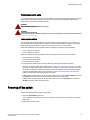
Recommendations for cable management..................................................... 30
Operating the Switch...............................................................................................................31
Brocade 7840 Extension Switch Hardware Reference Manual
53-1003127-02
3
LED activity................................................................................................... 31
LEDs on the port side of the Extension Switch................................. 31
LEDs on the nonport side of the switch............................................ 34
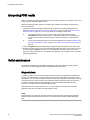
Interpreting POST results..............................................................................36
Switch maintenance......................................................................................36
Diagnostic tests.................................................................................36
Field-replaceable units...................................................................... 37
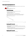
Powering off the switch................................................................................. 37
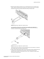
Removing and replacing transceivers........................................................... 38
Time and items required................................................................... 38
Removing an SFP+ transceiver........................................................ 38
Replacing an SFP+ transceiver........................................................ 38
Removal and Replacement of Power Supplies and Fans.........................................................41
Removal and replacement introduction........................................................ 41
Before beginning replacement.......................................................... 41
Power supply removal and replacement....................................................... 42
Determining the need to replace a power supply..............................42
Time and items required................................................................... 43
Replacing a power supply................................................................. 43
Fan removal and replacement...................................................................... 44
Determining the need to replace a fan.............................................. 45
Time and items required................................................................... 45
Replacing a Brocade 7840 fan..........................................................45
Brocade 7840 Technical Specifications................................................................................ 47
Regulatory Statements..........................................................................................................55
BSMI statement (Taiwan)..............................................................................55
Canadian requirements.................................................................................55
CE Statement................................................................................................55
China CC statement......................................................................................56
FCC warning (US only)................................................................................. 56
Germany....................................................................................................... 57
KCC statement (Republic of Korea)..............................................................57
VCCI statement.............................................................................................57
Cautions and Danger Notices................................................................................................ 59
Cautions........................................................................................................59
Danger Notices............................................................................................. 61
Index.................................................................................................................................... 65
4
Brocade 7840 Extension Switch Hardware Reference Manual
53-1003127-02
Preface
● Document conventions......................................................................................................5
● Brocade resources............................................................................................................ 7
● Contacting Brocade Technical Support.............................................................................7
● Document feedback.......................................................................................................... 8
Document conventions
The document conventions describe text formatting conventions, command syntax conventions, and
important notice formats used in Brocade technical documentation.
Text formatting conventions
Text formatting conventions such as boldface, italic, or Courier font may be used in the flow of the text
to highlight specific words or phrases.
Format
Description
bold text
Identifies command names
Identifies keywords and operands
Identifies the names of user-manipulated GUI elements
Identifies text to enter at the GUI
italic text
Identifies emphasis
Identifies variables and modifiers
Identifies paths and Internet addresses
Identifies document titles
Courier font
Identifies CLI output
Identifies command syntax examples
Command syntax conventions
Bold and italic text identify command syntax components. Delimiters and operators define groupings of
parameters and their logical relationships.
Convention
Description
bold text
Identifies command names, keywords, and command options.
italic text
Identifies a variable.
Brocade 7840 Extension Switch Hardware Reference Manual
53-1003127-02
5
Notes, cautions, and warnings
Convention
Description
value
In Fibre Channel products, a fixed value provided as input to a command
option is printed in plain text, for example, --show WWN.
[]
Syntax components displayed within square brackets are optional.
Default responses to system prompts are enclosed in square brackets.
{x|y|z}
A choice of required parameters is enclosed in curly brackets separated by
vertical bars. You must select one of the options.
In Fibre Channel products, square brackets may be used instead for this
purpose.
x|y
A vertical bar separates mutually exclusive elements.
<>
Nonprinting characters, for example, passwords, are enclosed in angle
brackets.
...
Repeat the previous element, for example, member[member...].
\
Indicates a “soft” line break in command examples. If a backslash separates
two lines of a command input, enter the entire command at the prompt without
the backslash.
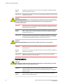
Notes, cautions, and warnings
Notes, cautions, and warning statements may be used in this document. They are listed in the order of
increasing severity of potential hazards.
NOTE
A Note provides a tip, guidance, or advice, emphasizes important information, or provides a reference
to related information.
ATTENTION
An Attention statement indicates a stronger note, for example, to alert you when traffic might be
interrupted or the device might reboot.
CAUTION
A Caution statement alerts you to situations that can be potentially hazardous to you or cause
damage to hardware, firmware, software, or data.
DANGER
A Danger statement indicates conditions or situations that can be potentially lethal or
extremely hazardous to you. Safety labels are also attached directly to products to warn of
these conditions or situations.
6
Brocade 7840 Extension Switch Hardware Reference Manual
53-1003127-02
Brocade resources
Brocade resources
Visit the Brocade website to locate related documentation for your product and additional Brocade
resources.
You can download additional publications supporting your product at www.brocade.com. Select the
Brocade Products tab to locate your product, then click the Brocade product name or image to open the
individual product page. The user manuals are available in the resources module at the bottom of the
page under the Documentation category.
To get up-to-the-minute information on Brocade products and resources, go to MyBrocade. You can
register at no cost to obtain a user ID and password.
Release notes are available on MyBrocade under Product Downloads.
White papers, online demonstrations, and data sheets are available through the Brocade website.
Contacting Brocade Technical Support
As a Brocade customer, you can contact Brocade Technical Support 24x7 online, by telephone, or by email. Brocade OEM customers contact their OEM/Solutions provider.
Brocade customers
For product support information and the latest information on contacting the Technical Assistance
Center, go to http://www.brocade.com/services-support/index.html.
If you have purchased Brocade product support directly from Brocade, use one of the following methods
to contact the Brocade Technical Assistance Center 24x7.
Online
Telephone
E-mail
Preferred method of contact for nonurgent issues:
Required for Sev 1-Critical and Sev
2-High issues:
[email protected]
• My Cases through MyBrocade
•
Continental US: 1-800-752-8061
• Software downloads and licensing •
tools
Europe, Middle East, Africa, and
Asia Pacific: +800-AT FIBREE
(+800 28 34 27 33)
• Knowledge Base
•
For areas unable to access toll
free number: +1-408-333-6061
•
Toll-free numbers are available in
many countries.
Please include:
•
Problem summary
•
Serial number
•
Installation details
•
Environment description
Brocade OEM customers
If you have purchased Brocade product support from a Brocade OEM/Solution Provider, contact your
OEM/Solution Provider for all of your product support needs.
• OEM/Solution Providers are trained and certified by Brocade to support Brocade® products.
• Brocade provides backline support for issues that cannot be resolved by the OEM/Solution Provider.
Brocade 7840 Extension Switch Hardware Reference Manual
53-1003127-02
7
Document feedback
• Brocade Supplemental Support augments your existing OEM support contract, providing direct
access to Brocade expertise. For more information, contact Brocade or your OEM.
• For questions regarding service levels and response times, contact your OEM/Solution Provider.
Document feedback
To send feedback and report errors in the documentation you can use the feedback form posted with
the document or you can e-mail the documentation team.
Quality is our first concern at Brocade and we have made every effort to ensure the accuracy and
completeness of this document. However, if you find an error or an omission, or you think that a topic
needs further development, we want to hear from you. You can provide feedback in two ways:
• Through the online feedback form in the HTML documents posted on www.brocade.com.
• By sending your feedback to [email protected].
Provide the publication title, part number, and as much detail as possible, including the topic heading
and page number if applicable, as well as your suggestions for improvement.
8
Brocade 7840 Extension Switch Hardware Reference Manual
53-1003127-02
About This Document
● Supported software........................................................................................................... 9
● What’s new in this document............................................................................................ 9
Supported software
This document includes information specific to the Brocade 7840 running Brocade Fabric version OS
7.3 and later.
What’s new in this document
The following changes have been made since this document was last released:
• Added information about the SFPs included with the switch.
• Reorganized the table listing the weight specifications of the switch.
Brocade 7840 Extension Switch Hardware Reference Manual
53-1003127-02
9
What’s new in this document
10
Brocade 7840 Extension Switch Hardware Reference Manual
53-1003127-02
Introducing the Brocade 7840 Extension Switch
● Overview of Brocade 7840 Extension Switch................................................................. 11
● Port side of the switch..................................................................................................... 13
● Nonport side of the switch...............................................................................................14
● Switch management........................................................................................................16
Overview of Brocade 7840 Extension Switch
The Brocade 7840 Extension Switch is intended as a platform for Fibre Channel over IP (FCIP). This
enables transmission of Fibre Channel data over long distances by way of IP networks by wrapping
Fibre Channel frames in IP packets. Each end of the FCIP communication path must be a compatible
FCIP device.
The switch can operate independently or in a fabric containing multiple extension switches.
Brocade 7840 software features
The Brocade 7840 provides the following software features:
• Multiple logical FCIP tunnels with maximum tunnel bandwidth up to 20Gbps allow for scalable
connectivity between sites. Note that the 7840 does not support FCIP connectivity with any other
products including the Brocade 7800 and FX8-24.
• FCIP Trunking feature allows multiple IP source and destination address pairs (defined as FCIP
circuits) via multiple 1/10GbE or 40GbE interfaces to provide high bandwidth FCIP tunnel and
lossless failover resiliency. In addition, each FCIP circuit supports four QoS classes (Class-F, High,
Medium and Low Priority), each as a TCP connection.
• ARL feature meets minimum bandwidth guarantee for each tunnel while making the full utilization of
the available network bandwidth without adverse throughput performance impact at high traffic load.
• Hardware-based compression delivers the ability to maximize throughput over lower bandwidth links
in the wide area network, optimizing the cost efficiencies of FCIP. The 7840 compresses FC frames
before they are encapsulated into FCIP packets.
• Key protocol features are enabled in the FCIP implementation to optimize performance of Extension
over IP networks, including FX8-24 and WAN Optimized TCP (WO-TCP), 9K jumbo frame and endto-end Path MTU auto discovery.
• Hardware-based IPsec supports mix of secure and non-secure tunnels on the same Ethernet port,
jumbo frames, and VLAN tagged connections. The Brocade 7840 IPsec function is capable of
supporting both IPv4 and IPv6.
• FastWrite, Open Systems Tape Pipelining and Advanced Accelerator for FICON mitigate the latency
effect of a long distance FCIP distance connection over IP WAN.
• FCIP HCL (Hot Code Load) provides In-service firmware upgrade for supporting 24/7 non-stop
business operations
• Built-in WAN link tester generates traffic over an IP connection to test for maximum throughput,
congestion, loss percentage, out of order deliver, latency, and other network conditions. It helps
determine the health of a WAN link before deploying it for use.
• Fabric Vision advanced monitoring provides the following functions:
Brocade 7840 Extension Switch Hardware Reference Manual
53-1003127-02
11
Brocade 7840 hardware features
‐
Policy based monitoring monitors FCIP connectivity and WAN anomalies using multi-layer
metrics.
‐
Flow monitoring reports IOPS and data rate of individual I/O flows of inter-DC replication
and tape backup operations.
‐
Flow generator generates FC frames for a defined flow with default or custom size and
pattern and sent across FCIP tunnel to help validate end to end network setup and
configuration.
• Brocade Fabric OS delivers distributed intelligence throughout the network and enables a wide
range of value-added applications.
Brocade 7840 hardware features
The Brocade 7840 provides the following hardware features:
• 24 Fibre Channel ports with link speeds of 2, 4, 8, and 16 Gbps, compatible with short wavelength
(SWL), long wavelength (LWL) and extended long wavelength (ELWL) SFP+ transceivers
• Rack-mountable 2U chassis
• Sixteen 1 GbE/10 GbE ports, compatible with copper, ultra short reach (USR), short reach (SR) and
long reach (LR) SFP/SFP+ transceivers
• Two 40 GbE ports, compatible with short reach (SR) and long reach (LR) QSFP transceivers
• One RJ-45 Ethernet management port with 10/100/1000 Mbps autonegotiating capability
• One USB port that provides storage for firmware updates, output of the supportSave command,
and storage for configuration uploads and downloads
• Two redundant, hot-swappable 1100 W AC/DC power supply units (PSUs) with integral fans
• 3 port-side exhaust DC fan FRUs
NOTE
QSFPs used in the FC16-64 blades (and 8510 core blades) are not compatible with the Brocade 7840.
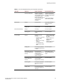
Brocade 7840 feature licensing
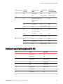
The Brocade 7840 provides the following licensing features:
• Tiered WAN throughput licensing provides coverage of multiple customer segments with one
physical platform:
NOTE
The application throughput numbers shown in the following table assume that some degree of data
compression is occurring. However, Brocade makes no promises, guarantees, or any indication that
some level of compression is possible for customer-specific data. Some data is highly compressible
and some data cannot be compressed. The amount of application throughput varies depending on
data compressibility and the selected compression mode.
12
Product
configuration
FC Ports
Ethernet Ports
WAN rate limiting
Approximate
Application
throughput
Base configuration
24 16G
16 1/10GbE
5 Gbps
15 Gbps (see note
above)
Brocade 7840 Extension Switch Hardware Reference Manual
53-1003127-02
Available licenses
Medium
configuration (Base
+ WAN Rate
Upgrade 1)
24 16G
16 1/10GbE
10 Gbps
30 Gbps (see note
above)
Max configuration
(Base + WAN Rate
Upgrade 1 and
WAN Rate Upgrade
2)
24 16G
16 1/10GbE + 2
40GbE
Unlimited
80 Gbps (see note
above)
• Two base unit SKUs:
‐
‐
One SKU with SWL SFPs (Enterprise Bundle and Advanced Extension are included)
One SKU with LWL SFPs (Enterprise Bundle and Advanced Extension are included)
• Streamlined feature licensing:
‐
‐
The Brocade 7840 uses common licenses with other midrange products (e.g. Brocade
6510) for IR and CUP.
A new SKU for Advanced Acceleration for FICON license on the Brocade 7840 is
introduced.
• All ports and interfaces on the switch are active except for the 40GE interfaces. The 40GE interfaces
are enabled as part of WAN Rate Upgrade 2.
Available licenses
The following features are available with the purchase of a specific license key for the Brocade 7840:
•
•
•
•
•
Integrated Routing (IR)
Advanced Acceleration for FICON
FICON CUP
WAN Rate Upgrade 1
WAN Rate Upgrade 2
For information on these features, refer to the Fabric OS Administrator's Guide.
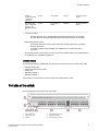
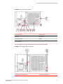
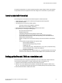
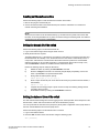
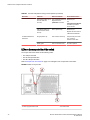
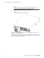
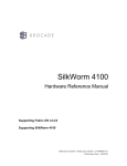
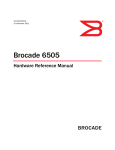
Port side of the switch
The following figures show the port side of the switch.
1
2
3
System Status LED
Power Status LED
USB port
Brocade 7840 Extension Switch Hardware Reference Manual
53-1003127-02
4
5
6
Ethernet Management port
Console port (RJ-45)
Serial number pull-out tab
13
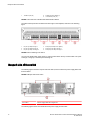
Nonport side of the switch
7
16 GbE FC ports (24)
8
9
40 GbE FCIP ports (QSFP) (2)
1/10 GbE FCIP ports (16)
FIGURE 1 Port side view of the Brocade 7840 Extension Switch
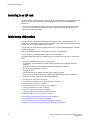
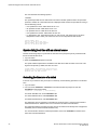
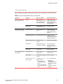
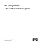
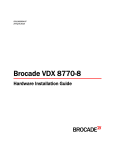
The Fibre Channel ports are numbered from left to right on the faceplate, as shown in the following
figure.
1
2
3
FC ports (16 GbE) 0 through 7
FC ports (16 GbE) 8 through 15
FC ports (16 GbE) 16 through 23
4
5
6
FCIP ports (40 GbE) 0 and 1 (QSFP)
FCIP ports (1/10 GbE) 2 through 9
FCIP ports (1/10 GbE) 10 through 17
FIGURE 2 Port numbering in the switch
You can have two Brocade Trunk groups on a fully licensed switch. Group 1 would consist of FC ports
0 through 7 and group 2 would be ports 8 through 15.
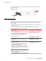
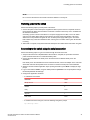
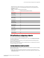
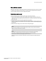
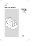
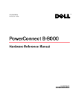
Nonport side of the switch
The following figure shows the nonport side of the switch, which contains two power supply FRUs and
three fan FRUs.
FIGURE 3 Nonport side of the switch
1 Fan FRUs
2 Power supply FRUs with integral fans
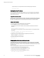
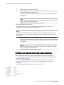
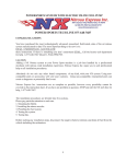
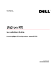
The following figure shows more details about the power supply and fan FRUs.
14
Brocade 7840 Extension Switch Hardware Reference Manual
53-1003127-02
Introducing the Brocade 7840 Extension Switch
FIGURE 4 Power supply and fan details
1 AC power socket
5 AC status LED
2 Handle
6 Fan air inlet
3 Integral fan air inlet
7 Handle
4 DC status LED
The following figure shows the airflow labels on the power supply and fan FRUs.
FIGURE 5 Power supply and fan airflow labels
1 Airflow label for PSU integral fan
Brocade 7840 Extension Switch Hardware Reference Manual
53-1003127-02
2 Airflow label for fan FRU
15
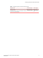
Switch management
The following figure shows the fan airflow (Intake only) for the Brocade 7840. Exhaust airflow is not
supported in this release.
FIGURE 6 Fan airflow
Switch management
You can use the management functions built into the switch to monitor the fabric topology, port status,
physical status, and other information to help you analyze switch performance and to accelerate
system debugging.
For information about upgrading the version of Fabric OS installed on your switch, refer to the Fabric
OS Administrator's Guide
You can manage the switch using any of the management options listed in the following table.
TABLE 1 Management options for the Brocade 7840
Management tool
Out-of-band support
In-band support
Command line interface (CLI)
Ethernet (preferred) or
console port connection
IP over Fibre
Channel
Brocade Network Advisor
Ethernet (preferred) or
console port connection
IP over Fibre
Channel
Brocade Web Tools
Ethernet (preferred) or
console port connection
IP over Fibre
Channel
Ethernet (preferred) or
console port connection
IP over Fibre
Channel
Up to two admin sessions and four user sessions simultaneously.
For more information, refer to the Fabric OS Administrator's
Guide and the Fabric OS Command Reference.
For information, refer to the Web Tools Administrator's Guide.
Standard SNMP applications
You can download the Brocade-specific MIB files from the
downloads area of the MyBrocade site under the applicable
Fabric Operating System (FOS) release.
For information about SNMP support in Fabric OS and how to
use MIBs, refer to the Fabric OS Administrator's Guide. For
release-specific SNMP enhancements, refer to the release notes.
NOTE
Distribution of standard MIBs has been stopped. Download the
required standard MIBs from the www.oidview.com or
www.mibdepot.com web sites.
16
Brocade 7840 Extension Switch Hardware Reference Manual
53-1003127-02
Introducing the Brocade 7840 Extension Switch
TABLE 1 Management options for the Brocade 7840 (Continued)
Management tool
Out-of-band support
In-band support
Management Server
Ethernet (preferred) or
console port connection
Native in-band
interface (over HBA
only)
For information, refer to the Fabric OS Administrator's Guide and
the Fabric OS Command Reference.
Brocade 7840 Extension Switch Hardware Reference Manual
53-1003127-02
17
Switch management
18
Brocade 7840 Extension Switch Hardware Reference Manual
53-1003127-02
Installing and Configuring the Switch
● Installation and safety considerations............................................................................. 19
● Installation Precautions................................................................................................... 20
● Items included with the switch.........................................................................................21
● Setting up the Brocade 7840 as a standalone unit......................................................... 21
● Installing in an EIA rack...................................................................................................22
● Initial setup of the switch................................................................................................. 22
● Recommendations for cable management..................................................................... 30
Installation and safety considerations
You can install the switch in the following ways:
• As a standalone unit on a flat surface.
• In an EIA rack using the Universal Two-Post Rack Kit or Universal Four-Post Rack Kit.
To install and operate the switch successfully, ensure that the following requirements are met:
• The primary AC input is 100-240 VAC (Brocade 7840 autosenses input voltage), 50-60 Hz. 200-240
VAC is recommended.
• The primary outlet is correctly wired, protected by a circuit breaker, and grounded in accordance with
local electrical codes. It is best practice that each power supply obtain its power from a different
protected and wired source. It is best practice that each power supply obtain its power from a
different protected and wired source.
• The supply circuit, line fusing, and wire size are adequate, as specified by the electrical rating on the
Brocade 7840 nameplate.
For power supply information, refer to Power supplies and fans on page 37.
To ensure adequate cooling, install the Brocade 7840 with the nonport side, which contains the air
intake vents, facing a cool-air aisle.
CAUTION
Make sure the airflow around the front, sides, and back of the device is not restricted.
Verify that the ambient air temperature does not exceed 40°C ( 104°F) and that the ambient humidity
remains between 20 and 85 percent while the Brocade 7840 is operating.
CAUTION
Do not install the device in an environment where the operating ambient temperature might
exceed 40°C (104°F).
If installing the Brocade 7840 in a rack:
• The rack must be a standard EIA rack.
• Plan for a rack space that is 2U ( 8.89 cm; 3.5 in.), (19 in.) 48.3 cm wide, and at least 61cm (24 in.)
deep.
• Ground all equipment in the rack through a reliable branch circuit connection and maintain ground at
all times. Do not rely on a secondary connection to a branch circuit, such as a power strip.
Brocade 7840 Extension Switch Hardware Reference Manual
53-1003127-02
19
Installation Precautions
• Ensure that airflow and temperature requirements are met on an ongoing basis.
• Verify that the additional weight of the Brocade 7840 does not exceed the rack’s weight limits or
unbalance the rack in any way.
DANGER
Make sure the rack housing the device is adequately secured to prevent it from becoming
unstable or falling over.
Installation Precautions
Review all installation precautions before installing the device.
General precautions
DANGER
The procedures in this manual are for qualified service personnel.
CAUTION
Changes or modifications made to this device that are not expressly approved by the party
responsible for compliance could void the user's authority to operate the equipment.
DANGER
All fiber-optic interfaces use Class 1 lasers.
Power Precautions
This Extension Switch might have more than one power cord. To reduce the risk of electric shock,
disconnect both power cords before servicing.
DANGER
Remove both power cords before servicing.
DANGER
Disconnect the power cord from all power sources to completely remove power from the
device.
CAUTION
Before plugging a cable into to any port, be sure to discharge the voltage stored on the cable
by touching the electrical contacts to ground surface.
Connect the power cord only to a grounded outlet.
DANGER
Make sure that the power source circuits are properly grounded, then use the power cord
supplied with the device to connect it to the power source.
20
Brocade 7840 Extension Switch Hardware Reference Manual
53-1003127-02
Items included with the switch
This product is designed for an IT power system with phase-to-phase voltage of 230V. After operation
of the protective device, the equipment is still under voltage if it is connected to an IT power system.
Items included with the switch
The following items are included with the standard shipment of the Brocade 7840:
• The Brocade 7840, containing two combined power supply FRUs with integral fans
• Three individual fan FRUs
• The following rack mount kits are available options:
‐
Fixed rack mount kit, with installation instructions
‐
Mid-mount kit, with installation instructions
• All Fibre Channel ports contain 16 Gbps SWL or LWL SFP transceivers
• One accessory kit, containing the following items:
‐
‐
‐
‐
‐
‐
‐
‐
‐
Brocade 7840 QuickStart Guide
EZSwitchSetup CD Kit
China-ROHS Hazardous/Toxic Substance Content Chart
Documentation reference card (describes where to find relevant documentation)
24 16 G Brocade branded SWL or LWL SFPs, depending on the switch SKU ordered
Network Advisor download insert
Rubber mounting feet (to be used when setting up the Extension Switch as a standalone
unit)
Two grounded 6-ft. (approximately 1.83 m) power cords:
‐
Power plug type: NEMA5-15
‐
Power plug current/voltage rating: 15A/125V
‐
Cordage type: SJT
‐
Current rating/wire gauge: 13A/16AWG with a 105°C (221°F) temperature rating
‐
Connector at system end of cordset: IEC 60320/C13
‐
Two power cord retainers
One RJ-45 serial cable (10 ft. or approximately 3 m.). The Extension Switch uses an RJ-45
connector for the console port. An RJ-45 to DB-9 adapter is also provided with the switch.
Setting up the Brocade 7840 as a standalone unit
The Brocade 7840 can be configured as a standalone unit, which means that it resides outside of a
rack. Perform the following steps to configure the Brocade 7840 as a standalone unit.
1. Unpack the Brocade 7840 and verify that all ordered items are present.
2. Clean the four corner depressions on the bottom of the Brocade 7840 and place a rubber foot in
each one. This helps prevent the Brocade 7840 from accidentally sliding off the supporting surface.
3. Place the Brocade 7840 on a stable, flat surface.
Brocade 7840 Extension Switch Hardware Reference Manual
53-1003127-02
21
Installing in an EIA rack
Installing in an EIA rack
The Brocade 7840 can be installed in an EIA rack using one of the following optionally available rackmount kits. Refer to the documentation that is shipped with the rack-mount kit for installation
instructions:
• Universal Four-Post Rack Kit Installation Procedure Supporting Brocade 7840 Extension Switch
• Universal Two-Post Rack Kit Installation Procedure Supporting the Brocade VDX 6740T and
Brocade 7840 Extension Switch.
Initial setup of the switch
The switch must be configured correctly before it can operate within a network and fabric. For
instructions on configuring the switch to operate in a fabric containing Extension Switches from other
vendors, refer to the Fabric OS Administrator's Guide.
If you are going to use the switch in a single-switch setup, you can use EZSwitchSetup to complete
the basic configuration.
Refer to the EZSwitchSetup CD, included with the switch for more information.
If you do not want to use EZSwitchSetup, refer to the following steps.
The following items are required for configuring and connecting the switch for use in a network and
fabric:
• The switch, installed and connected to a power source
• A workstation computer that has a terminal emulator application (such as HyperTerminal for
Windows)
• An unused IP address and corresponding subnet mask and gateway address
• The serial cable provided with the switch
• An Ethernet cable
• SFP transceivers and compatible fiber and copper cables, as required
• Access to an FTP server, for backing up (uploading) or downloading the switch configuration
To configure the switch, you must perform the following tasks:
1. Providing power to the switch on page 23
2. Connecting to the switch using the serial connection on page 23
3. Setting the switch IP address on page 24
4. Changing the switch name and chassis name on page 24
5. Creating an Ethernet connection on page 25
6. Setting the domain ID of the switch on page 25
7. Installing transceivers and cabling the switch on page 27
8. Setting the date and time of the switch on page 25
9. Synchronizing local time with an external source on page 26
10.Correcting the time zone of a switch on page 26
11.FCIP and Fibre Channel routing services configuration on page 27
12.Verifying correct operation and backing up the configuration on page 28
22
Brocade 7840 Extension Switch Hardware Reference Manual
53-1003127-02
Providing power to the switch
NOTE
Do not connect the switch to the network until the IP address is correctly set.
Providing power to the switch
Perform the following steps to provide power to the switch.
1. Connect the power cords to both power supplies and then to power sources on separate circuits to
protect against AC failure. Ensure that the cords have a minimum service loop of 6 in. available and
are routed to avoid stress.
Connecting a power cord turns the switch on. The power supply has two LEDs, one for AC status
and one for DC status. Both LEDs go green within a second of power being applied. The Power
Status LED on the portside turns green as soon as either power supply LED is green. The status
LED is amber only until FOS is loaded and then it turns green. The status LED is green while POST
is running.
2. After POST is complete, verify that the Brocade 7840 power and status LEDs of the switch are green.
Connecting to the switch using the serial connection
Perform the following steps to log in to the switch through the serial connection.
1. Verify that the switch has completed POST. When POST is complete, the port status and switch
power and status LEDs return to a standard healthy state.
2. Connect the serial cable to the serial port on the switch and to an RS-232 serial port on the
workstation.
If the serial port on the workstation is RJ-45 instead of RS-232, remove the adapter on the end of the
serial cable and insert the exposed RJ-45 connector into the RJ-45 serial port on the workstation.
3. When the terminal emulator application stops reporting information, press Enter to display the login
prompt.
4. Log in to the switch as admin, using the default password: password. You are prompted to change
the default passwords at initial login.
5. Configure the application as follows:
• In a Windows environment:
Parameter
Value
Bits per second
9600
Databits
8
Parity
None
Stop bits
1
Flow control
None
• In a UNIX environment using TIP, enter the following string at the prompt:
tip /dev/ttyb -9600.
Brocade 7840 Extension Switch Hardware Reference Manual
53-1003127-02
23
Setting the switch IP address
If ttyb is already in use, use ttya instead and enter the following string at the prompt:
tip /dev/ttya -9600
Setting the switch IP address
You can configure the switch with a static IP address, or you can use a Dynamic Host Configuration
Protocol (DHCP) server to set the IP address of the switch. DHCP is enabled by default. The switch
supports both IPv4 and IPv6.
Using DHCP to set the IP address
When using DHCP, the switch obtains its IP address, subnet mask, and default gateway address from
the DHCP server. The DHCP client can only connect to a DHCP server that is on the same subnet as
the switch. If your DHCP server is not on the same subnet as the switch, use a static IP address.
Setting a static IP address
1. Log in to the switch using the default password, which is password.
2. Use the ipaddrset command to set the Ethernet IP address.
If you are going to use an IPv4 IP address, enter the IP address in dotted decimal notation as
prompted.
Ethernet IP Address: [192.168.74.102]
If you are going to use an IPv6 address, enter the network information in colon-separated notation
as prompted.
switch:admin> ipaddrset -ipv6 --add 1080::8:800:200C:417A/64
IP address is being changed...Done.
3. Complete the rest of the network information as prompted. (IPv4 format shown):
Ethernet Subnetmask: [255.255.255.0]
Ethernet IP Address: [192.168.74.102]
Gateway IP Address: [192.168.74.1]
4. Enter off to disable DHCP when prompted.
DHCP [OFF]: off
Changing the switch name and chassis name
Changing the switch and chassis names are important for accurate tracking of errors in the RASlog.
The messages that appear in the log will be labeled with the switch or chassis name, which makes
tracking the errors much easier. Choose an easily understandable and meaningful name for the switch
and chassis names.
Perform the following steps to change the chassis name and then the switch name.
1. Log in to the switch through Telnet using the admin account.
2. Change the chassis name by using the chassisName command.
switch:admin> chassisname my7840chassis
3. Change the switch name by using the switchName command.
switch:admin> switchname my7840switch
24
Brocade 7840 Extension Switch Hardware Reference Manual
53-1003127-02
Creating an Ethernet connection
Creating an Ethernet connection
Perform the following steps to create an Ethernet connection to the switch.
1. Remove the plug from the Ethernet port.
2. Connect an Ethernet cable to the switch Ethernet port and to the workstation or to an Ethernet
network containing the workstation.
NOTE
At this point, the switch can be accessed remotely, by command line or by Web Tools. Ensure that
the switch is not being modified from any other connections during the remaining tasks. The Ethernet
management port also supports AutoMDI/MDIX.
Setting the domain ID of the switch
Perform the following steps to set the switch domain ID.
1. Log in to the switch through Telnet using the admin account.
2. Modify the domain ID if required.
The default domain ID is 1. If the switch is not powered on until after it is connected to the fabric and
the default domain ID is already in use, the domain ID for the new switch is automatically reset to a
unique value. If the switch is connected to the fabric after it has been powered on and the default
domain ID is already in use, the fabric segments. To find the domain IDs that are currently in use,
enter the fabricShow command on another Extension Switch in the fabric.
Perform the following steps to modify the Domain ID.
a)
b)
c)
Disable the switch by entering the switchDisable command.
Enter the configure command. The command prompts display sequentially; enter a new
value or press Enter to accept each default value.
Enter y after the "Fabric param" prompt.
Fabric param (yes, y, no, n): [no] y
d)
Enter a unique domain ID (such as the domain ID used by the previous Extension Switch, if
still available).
Domain: (1..239) [1] 3
e)
f)
Complete the remaining prompts or press Ctrl+D to accept the remaining settings without
completing all the prompts.
Re-enable the switch by entering the switchEnable command.
Setting the date and time of the switch
The date and time switch settings are used for logging events. Switch operation does not depend on the
date and time; a switch with incorrect date or time values still functions properly.
You can synchronize the local time of the principal or primary fabric configuration server (FCS) switch to
that of an external Network Time Protocol (NTP) server.
Perform the following steps to set the date and time of a switch.
1. Log in to the switch as admin.
2. Enter the date command at the command line using the following syntax:
date ["newdate"]
Brocade 7840 Extension Switch Hardware Reference Manual
53-1003127-02
25
Synchronizing local time with an external source
This command has the following operand:
"newdate"
This operand specifies the new date and time enclosed in double quotation marks. this operand is
optional; if omitted, the current date and time is displayed. Date and time are specified as a string in
the mmddhhmmyy format.
•
•
•
•
•
mm: Specifies the month. Valid values are 01 to 12.
dd: Specifies the date. Valid values are 01 to 31.
hh: Specifies the hour. Valid values are 00 to 23.
mm: Specifies the minutes. Valid values are 00 to 59.
yy: Specifies the year, valid values are 00 to 37 and 70 to 99. Year values from 70 to 99 are
interpreted as 1970 to 1999; year values from 00 to 37 are interpreted as 2000 to 2037.
switch:admin> date
Tue Oct 22 14:05:10 UTC 2013
switch:admin> date "1022140613"
Tue Oct 22 14:06:00 UTC 2013
Synchronizing local time with an external source
Perform the following steps to synchronize the local time of the principal or primary FCS switch with
that of an external NTP server.
1. Log in as admin.
2. Enter the tsClockServer ipaddr command.
The ipaddr variable represents the IP address of the NTP server that the switch can access. This
argument is optional; by default, the value is "LOCL".
sw7840:admin> tsclockserver 192.168.126.60
Updating Clock Server configuration...done.
Updated with the NTP servers
Correcting the time zone of a switch
If the time of your switch is off by hours (and not minutes), use the following procedure to set the time
zone.
1. Log in as admin.
2. You can use the tstimezone --interactive command and follow the prompts or enter the
tsTimeZone command as follows:
tstimezone
[houroffset [, minuteoffset]]
For Pacific Standard Time, enter tsTimeZone -8,0
For Central Standard Time, enter tsTimeZone -6,0
For Eastern Standard Time, enter tsTimeZone -5,0
The default time zone for switches is universal time conversion (UTC), which is 8 hours ahead of
Pacific Standard Time. Additional time zone conversions are listed in the table below.
The parameters listed do not apply if the time zone of the switches has already been changed from
the default (8 hours ahead of Pacific Standard Time).
For more information about the command parameters, refer to the tsTimeZone command in the
Fabric OS Command Reference.
26
Brocade 7840 Extension Switch Hardware Reference Manual
53-1003127-02
FCIP and Fibre Channel routing services configuration
Setting the time zone needs to be done only once, because the value is stored in nonvolatile
memory. For U.S. time zones, use the following table to determine the correct parameter for the
tsTimeZone command.
TABLE 2 tsTimeZone command parameter selection
Local time
tsTimeZone parameter (difference from UTC)
Atlantic Standard
-4,0
Atlantic Daylight
-3,0
Eastern Standard
-5,0
Eastern Daylight
-4,0
Central Standard
-6,0
Central Daylight
-5,0
Mountain Standard
-7,0
Mountain Daylight
-6,0
Pacific Standard
-8,0
Pacific Daylight
-7,0
Alaskan Standard
-9,0
Alaskan Daylight
-8,0
Hawaiian Standard
-10,0
FCIP and Fibre Channel routing services configuration
The ports on the switch are initially set to persistently disabled.
If you want to enable the FC ports as a standard E_Port or F_Port, use the portcfgpersistentenable
command to enable the ports.
If you are using the FC ports as EX_Ports, you must configure the Fibre Channel Routing Services
feature prior to enabling the ports.
Refer to the Fabric OS Administrator's Guide for detailed instructions on configuring the Fibre Channel
router ports and GbE ports on the switch.
Installing transceivers and cabling the switch
Perform the following steps to install SFP+ transceivers and cable the switch. The process for installing
QSFP transceivers is similar.
1. Install the SFP transceivers in the Fibre Channel ports, as required. The ports selected for use in
trunking groups must meet specific requirements. For a list of these requirements, refer to the Fabric
OS Administrator's Guide.
Brocade 7840 Extension Switch Hardware Reference Manual
53-1003127-02
27
Verifying correct operation and backing up the configuration
a)
b)
Remove the plug from the port to be used.
Position a transceiver so that it is oriented correctly and insert it into a port until it is firmly
seated and the latching mechanism clicks.
For instructions specific to the type of transceiver, refer to the transceiver manufacturer’s
documentation.
c)
NOTE
The transceivers are keyed to ensure correct orientation. If a transceiver does not install
easily, ensure that it is correctly oriented.
Repeat steps a and b for the remaining ports, as required.
2. Connect the cables to the transceivers.
The cables used in trunking groups must meet specific requirements. For a list of these
requirements, refer to the Fabric OS Administrator's Guide.
NOTE
A 50-micron cable should not be bent to a radius less than 2 in. under full tensile load and 1.2 in.
with no tensile load. Tie wraps are not recommended for optical cables because they are easily
overtightened.
a)
b)
Orient a cable connector so that the key (the ridge on one side of the connector) aligns
with the slot in the transceiver. Then, insert the cable into the transceiver until the latching
mechanism clicks. For instructions specific to cable type, refer to the cable manufacturer’s
documentation.
NOTE
The cable connectors are keyed to ensure correct orientation. If a cable does not install
easily, ensure that it is correctly oriented.
Repeat step a for the remaining cables as required.
Verifying correct operation and backing up the configuration
Perform the following steps to verify correct operation and back up the switch configuration.
1. Check the LEDs to verify that all components are functional. For information about LED patterns,
refer to LED activity on page 31.
2. Enter the portcfgpersistentenable command to activate the FC ports for FC operation.
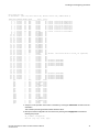
3. Verify the correct operation of the switch by entering the switchShow command from the
workstation.
This command provides information about switch and port status.
sb_70:admin> switchshow
switchName:
sb_70
switchType:
148.0
switchState:
Online
switchMode:
Native
switchRole:
Subordinate
switchDomain:
70
switchId:
fffc46
switchWwn:
10:00:00:05:1e:65:79:04
zoning:
ON (PERF_CFG)
switchBeacon:
OFF
FC Router:
OFF
28
Brocade 7840 Extension Switch Hardware Reference Manual
53-1003127-02
Installing and Configuring the Switch
Allow XISL Use: OFF
LS Attributes: [FID: 128, Base Switch: No, Default Switch: Yes, Address Mode 0]
Index Port Address Media Speed
State
Proto
==================================================
0
0
460000
id
N16
Online
FC
1
1
460100
id
N16
Online
FC
2
2
460200
id
N16
Online
FC
3
3
460300
id
N16
Online
FC
4
4
460400
id
N16
Online
FC
5
5
460500
id
N16
Online
FC
6
6
460600
id
N16
Online
FC
7
7
460700
id
N16
Online
FC
8
8
460800
-N16
No_Module
FC
9
9
460900
-N16
No_Module
FC
10 10
460a00
-N16
No_Module
FC
11 11
460b00
-N16
No_Module
FC
12 12
460c00
-N16
No_Module
FC
13 13
460d00
-N16
No_Module
FC
14 14
460e00
-N16
No_Module
FC
15 15
460f00
-N16
No_Module
FC
16 16
461000
-N16
No_Module
FC
17 17
461100
-N16
No_Module
FC
18 18
461200
-N16
No_Module
FC
19 19
461300
-N16
No_Module
FC
20 20
461400
-N16
No_Module
FC
21 21
461500
-N16
No_Module
FC
22 22
461600
-N16
No_Module
FC
23 23
461700
-N16
No_Module
FC
24 24
461800
--Online
VE
25 25
461900
--Offline
VE
26 26
461a00
--Offline
VE
27 27
461b00
--Offline
VE
28 28
461c00
--Offline
VE
29 29
461d00
--Offline
VE
30 30
461e00
--Offline
VE
31 31
461f00
--Offline
VE
32 32
462000
--Offline
VE
33 33
462100
--Offline
VE
34 34
462200
--Offline
VE
35 35
462300
--Offline
VE
36 36
462400
--Offline
VE
37 37
462500
--Offline
VE
38 38
462600
--Offline
VE
39 39
462700
--Offline
VE
40 40
462800
--Offline
VE
41 41
462900
--Offline
VE
42 42
462a00
--Offline
VE
43 43
462b00
--Offline
VE
ge0
-40G
Online
FCIP
ge1
-40G
No_Module FCIP
ge2
-10G
No_Sync
FCIP
ge3
-10G
Online
FCIP
ge4
-10G
No_Module FCIP
ge5
-10G
No_Sync
FCIP
ge6
-10G
Online
FCIP
ge7
-10G
Online
FCIP
ge8
-10G
Online
FCIP
ge9
-10G
Online
FCIP
ge10
-10G
Online
FCIP
ge11
-10G
Online
FCIP
ge12
-10G
Online
FCIP
ge13
-10G
No_Module FCIP
ge14
-10G
No_Module FCIP
ge15
-10G
No_Module FCIP
ge16
-10G
Online
FCIP
ge17
-10G
Online
FCIP
F-Port
F-Port
F-Port
F-Port
F-Port
F-Port
F-Port
F-Port
20:05:00:11:0d:a8:01:00
20:01:00:11:0d:bb:01:00
20:03:00:11:0d:84:01:00
20:07:00:11:0d:26:01:00
10:00:8c:7c:ff:5c:c5:01
10:00:8c:7c:ff:58:4c:00
10:00:8c:7c:ff:5c:c9:01
10:00:8c:7c:ff:5c:bd:00
VE-Port
10:00:00:05:1e:65:77:04 "sb_71" (upstream)
Disabled
Disabled
Disabled
Disabled
Disabled
(10VE
(10VE
(10VE
(10VE
(10VE
Mode)
Mode)
Mode)
Mode)
Mode)
Disabled
Disabled
Disabled
Disabled
Disabled
(10VE
(10VE
(10VE
(10VE
(10VE
Mode)
Mode)
Mode)
Mode)
Mode)
4. Verify the correct operation of the switch in the fabric by entering the fabricShow command from the
workstation.
This command provides general information about the fabric.
5. Back up the switch configuration to an FTP server by entering the configUpload command and
following the prompts.
sb_70:admin> configupload
Protocol (scp, ftp, local) [ftp]:
Brocade 7840 Extension Switch Hardware Reference Manual
53-1003127-02
29
Recommendations for cable management
Server Name or IP Address [host]: 192.168.0.100
User Name [user]: anonymous
Path/Filename [<home dir>/config.txt]:
Section (all|chassis|switch [all]): all
configUpload complete: All selected config parameters are uploaded
This command uploads the switch configuration to the server, making it available for downloading to
a replacement switch if necessary.
Brocade recommends backing up the configuration on a regular basis to ensure that a complete
configuration is available for downloading to a replacement switch. For specific instructions about
how to back up the configuration, refer to the Fabric OS Administrator's Guide. The switchShow,
fabricShow, and configUpload commands are described in detail in the Fabric OS Command
Reference
Recommendations for cable management
Cables can be organized and managed in a variety of ways, such as by using cable channels or patch
panels. Note the following recommendations:
• Plan cable management before installing the switch in a rack.
• Leave at least 1 meter (3 feet) of slack for each port cable. This provides room to remove and
replace the switch, allows for inadvertent movement of the rack, and helps prevent the cables from
being bent to less than the minimum bend radius.
NOTE
A 50-micron cable should not be bent to a radius less than 2 in. under full tensile load and 1.2 in. with
no tensile load. Tie wraps are not recommended for optical cables because they are easily
overtightened.
30
Brocade 7840 Extension Switch Hardware Reference Manual
53-1003127-02
Operating the Switch
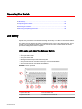
● LED activity..................................................................................................................... 31
● Interpreting POST results................................................................................................36
● Switch maintenance........................................................................................................ 36
● Powering off the switch................................................................................................... 37
● Removing and replacing transceivers............................................................................. 38
LED activity
System activity and status can be determined through the activity of the LEDs on the Extension Switch.
The status LEDs may display solid amber or flash during boot, POST, or other diagnostic tests. This is
normal; it does not indicate a problem unless the LEDs do not indicate a healthy state after all boot
processes and diagnostic tests are complete.
LEDs on the port side of the Extension Switch
The port side of the Extension Switch has the following LEDs:
•
•
•
•
•
One system status LED
One power status LED
Management Ethernet port speed and activity LEDs
One port status LED for each Fibre Channel port on the Extension Switch
One port status LED for each optical 10/40 GbE port
FIGURE 7 LEDs on port side
1 System Status LED
6 FC Port 4 Status LED
2 System Power LED
7 40 GbE FCIP Port 0 Status LED
Brocade 7840 Extension Switch Hardware Reference Manual
53-1003127-02
31
Operating the Switch
3 Ethernet Link LED
8 40 GbE FCIP Port 1 Status LED
4 Ethernet Status LED
9 1/10 GbE FCIP Port 4 Status LED
5 FC Port 0 Status LED
10 1/10 GbE FCIP Port 8 Status LED
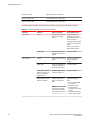
The following table describes the LEDs and their actions on the port side of the Extension Switch.
TABLE 3 Port side LED patterns during normal operation
LED name
LED color
Status of hardware
Recommended action
Power Status
No light
System is off or there is an Verify that system is
internal power supply
powered on, the power
failure.
cables attached, and your
power source is live.
If the system power LED is
not green, the unit may be
faulty.
Contact your Extension
Switch service provider.
System Status
Steady green
System is on and power
supplies are functioning
properly.
No light
System is off or there is no Verify that system is on
power.
and has completed
booting.
Steady green
POST and initialization is
completed. System is on
and functioning properly.
No action required.
Steady amber (for more
than five seconds)—can
take over a minute to
complete POST
System is going through
the power-up process.
No action required.
Steady amber (for more
than a few minutes)
Unknown state, boot
failed, or the system is
faulty.
Perform the following
steps:
NOTE
Once POST completes
and the switch has failed,
steady amber may result.
32
No action required.
1. Connect a serial cable
to the system.
2. Reboot the system.
3. Check the failure
indicated on the system
console
4. Contact your Extension
Switch service provider.
Brocade 7840 Extension Switch Hardware Reference Manual
53-1003127-02
Operating the Switch
TABLE 3 Port side LED patterns during normal operation (Continued)
LED name
Ethernet Link
Ethernet Status/Activity
FC Port Status
LED color
Status of hardware
Recommended action
Flashing amber/green
Attention is required. A
number of variables can
cause this status, including
a single power supply
failure, a fan failure, or one
or more environmental
ranges has been
exceeded.
Check the management
interface and the error log
for details on the cause of
the status.
No light
There is no link.
Verify that the Ethernet
cable is connected
correctly.
Steady green
There is a link.
No action required.
No light
No activity.
No action required.
Flashing green
There is link activity
(traffic).
No action required.
No light
Indicates one of the
following:
•
•
•
•
Contact your Extension
Switch service provider.
No signal or light carrier
•
(media or cable)
detected.
Blade may be currently
•
initializing.
Connected device is
configured in an offline
state.
Verify the power LED is
on, and check the SFP
and cable.
Verify the blade is not
currently being
initialized.
Verify the status of the
connected device.
Steady green
Port is online (connected
to external device) but has
no traffic.
No action required.
Slow-flashing green (on
1/2 second; then off 1/2
second)
Port is online but
segmented because of a
loopback cable or
incompatible Extension
Switch connection.
Verify that the correct
device is attached to the
switch.
Fast-flashing green (on 1/4 Port is online and an
second; then off 1/4
internal loopback
second)
diagnostic test is running.
No action required.
Flickering green
Port is online and frames
are flowing through the
port.
No action required.
Steady amber
Port is receiving light or
signal carrier, but it is not
online yet.
No action required.
Brocade 7840 Extension Switch Hardware Reference Manual
53-1003127-02
33
LEDs on the nonport side of the switch
TABLE 3 Port side LED patterns during normal operation (Continued)
LED name
10 GE/40 GE Ethernet
Port Status
LED color
Status of hardware
Recommended action
Slow-flashing amber (on 2
seconds; then off 2
seconds)
Port is disabled because of Reset the port.
diagnostics or the
The
portDisable command.
portCfgPersistentDisable
command is persistent
across reboots.
Fast-flashing amber (on
1/2 second; then off 1/2
second)
SFP or port is faulty.
No light (LED is off)
Port is offline. No activity.
Verify that the power LED
is on; check the
transceiver and cable.
Steady green
Port is online and active.
No action required.
Reset the port.
Replace the SFP. Must be
a Brocade-branded SFP.
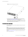
LEDs on the nonport side of the switch
The nonport side of the switch has the following LEDs:
• One LED per fan FRU
• One AC LED per PSU FRU
• One DC LED per PSU FRU
Refer to Nonport side of the switch on page 14 for a diagram of the nonport side of the switch.
FIGURE 8 LEDs on nonport side
1 Power supply DC status LED
34
3 Fan status LED
Brocade 7840 Extension Switch Hardware Reference Manual
53-1003127-02
Operating the Switch
2 Power supply AC status LED
The following table describes the LEDs and their actions on the nonport side of the Extension Switch.
TABLE 4 Nonport side LED patterns during normal operation
LED name
LED color
Status of hardware
Recommended action
Power supply AC input
status (one green LED)
No light
Power supply is not
receiving AC input voltage
or AC input voltage is
below operational limit.
Verify that the power
supply is properly seated
and the power cord is
connected to a functioning
AC power source.
Steady green
AC input voltage is within
operational range.
No action required.
Flashing amber (1:1)
Output voltage is not
enabled.
Verify that the power
supply is fully seated and
that the captive screw is
secured.
Power supply DC output
status (one bi-color LED)
Fan assembly status (one
bi-color LED)
Flashing amber/green (2:1) Over temperature warning.
Verify that ambient
temperature is less than
40°C (104°F) and check for
intake airflow blockage.
Flashing amber/green (1:1) Internal fan is out of
regulation.
Replace the power supply.
Steady amber
Power supply is faulty or
not plugged in completely.
Check the power cord,
current, voltage, and
temperature to determine
the problem.
Steady green
DC output OK.
No action required.
No light (LED is off)
Fan assembly is not
receiving power.
Verify that the fan FRU is
seated correctly.
Steady green
Fan assembly is operating
normally.
No action required.
Steady amber (for more
than 5 seconds)
Fan fault for one of the
following reasons:
Try one of the following:
• A fan assembly with
mismatched airflow is
present.
• One or more of the fans
in the fan assembly has
failed.
Brocade 7840 Extension Switch Hardware Reference Manual
53-1003127-02
• Replace the
mismatched fan
assembly with one that
has the correct airflow
direction.
• Replace the faulty fan
assembly.
35
Interpreting POST results
Interpreting POST results
POST is a system check that is performed each time the switch is powered on, rebooted, or reset, and
during which the LEDs flash different colors.
Perform the following steps to determine whether POST completed successfully and whether any
errors were detected.
1. Verify that the LEDs on the switch indicate that all components are healthy (LED patterns are
described in LEDs on the port side of the Extension Switch on page 31 and LEDs on the nonport
side of the switch on page 34). If one or more LEDs do not display a healthy state:
a)
b)
Verify that the LEDs are not set to "beacon" (this can be determined through the
switchShow command or Web Tools). For information about how to turn beaconing on
and off, refer to the Fabric OS Administrator's Guide or the Web Tools Administrator's
Guide.
Follow the recommended action for the observed LED behavior, as shown in LEDs on the
port side of the Extension Switch on page 31 or LEDs on the nonport side of the switch on
page 34.
2. Verify the diagShow command displays that the diagnostic status for all ports in the switch is OK.
3. Review the system log for errors. Errors detected during POST are written to the system log, which
is viewed using the errShow command. For more information about this command, refer to the
Fabric OS Command Reference. For information about specific error messages, refer to the Fabric
OS Message Reference.
Switch maintenance
The switch is designed for high availability and reliability; it does not require any regular physical
maintenance. It includes diagnostic tests and field-replaceable units (FRUs).
Diagnostic tests
In addition to POST, Fabric OS includes diagnostic tests to help you troubleshoot the hardware and
firmware. This includes tests of internal connections and circuitry, fixed media, and the transceivers
and cables in use. The tests are implemented by command, either through a Telnet session or through
a terminal set up for a serial connection to the Extension Switch. Some tests require the ports to be
connected by external cables to allow diagnostics to verify the serializer/deserializer interface,
transceiver, and cable. Some tests require loopback plugs.
Diagnostic tests are run at link speeds of 2-, 4-, 8-, and 16-Gbps. For information about specific
diagnostic tests, refer to the Fabric OS Administrator's Guide.
NOTE
Diagnostic tests may temporarily lock the transmit and receive speed of the links during diagnostic
testing. Brocade recommends that you power-cycle the switch after completing offline diagnostics
tests.
36
Brocade 7840 Extension Switch Hardware Reference Manual
53-1003127-02
Field-replaceable units
Field-replaceable units
You can replace the power supply and fan assemblies on-site without the use of special tools. The fieldreplaceable units (FRUs) are keyed to ensure correct orientation during installation. Replacement
instructions are provided with all FRUs ordered.
DANGER
Remove both power cords before servicing.
DANGER
Disconnect the power cord from all power sources to completely remove power from the device.
Power supplies and fans
The two PSU FRUs are hot-swappable. They are identical and fit into either bay. They are keyed to
prevent being inserted upside down. Each PSU has an input rated voltage of 100-240 V and a typical
Input operating range of 90-264 V. Output is 12 V which can drive up to 1100 W load.
Fabric OS identifies the power supplies as follows (viewing the switch from the nonport side):
• Power supply #1 on the right
• Power supply #2 on the left
Fabric OS identifies the fan assemblies as follows (viewing the switch from the nonport side):
• Fan assembly #1 on the right
• Fan assembly #2 in the middle
• Fan assembly #3 on the left
Any of the following methods can be used to determine whether a FRU requires replacing:
• Check the AC Status and DC Status LEDs (refer to LEDs on the nonport side of the switch on page
34). If the AC Status LED is black, verify that you are using the correct cord and power source. If the
DC Status LED is black or flashing, then the FRU should be replaced. Refer to the table describing
nonport side LED patterns during normal operation in LEDs on the nonport side of the switch on
page 34 for information about power supply faulty states.
• In BNA, double-click the switch icon to open Web Tools, and then click the Power Status icon. Enter
the psShow command at the command prompt to display power supply status.
• In BNA, double-click the switch icon to open Web Tools, then click the Fan Status icon. Enter the
fanShow command at the command prompt.
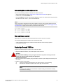
Powering off the switch
Perform the following steps to power off the switch.
1. Enter the sysShutdown command.
This command not only shuts down the key processors but also powers off the switch and all LEDs
will go dark.
2. Unplug the AC power cords.
Brocade 7840 Extension Switch Hardware Reference Manual
53-1003127-02
37
Removing and replacing transceivers
Removing and replacing transceivers
Use the following procedure to remove and replace an SFP+ transceiver. The process for removing
and replacing QSFP transceivers is the same.
DANGER
All fiber-optic interfaces use Class 1 lasers.
Time and items required
The replacement procedure for one transceiver takes less than five minutes.
You should have the following items available:
• Replacement SFP+ transceiver
• Optical transceiver extraction tool (for 8 or 10 Gbps transceiver only)
Most Brocade switches and backbones come with a transceiver extraction tool and holster. The
extraction tool is designed to remove transceivers from modules where the space is limited.
FIGURE 9 Optical transceiver extraction tool
Removing an SFP+ transceiver
Complete the following steps to remove an SFP+ transceiver.
1. Remove any cables that are inserted into the transceiver. Use the extraction tool to open the cable
latching mechanism.
2. Using the hooked end of the tool, pull the bail (wire handle) away from its pivot point and out, sliding
the transceiver out of the switch or module.
The 16 Gbps SFP+ transceivers have an attached pull tab. Instead of using the tool, simply grasp
the pull tab and pull straight out to remove the 16 Gbps SFP+ transceiver from the switch.
Replacing an SFP+ transceiver
Complete the following steps to replace an SFP+ transceiver.
38
Brocade 7840 Extension Switch Hardware Reference Manual
53-1003127-02
Operating the Switch
1. Making sure that the bail (wire handle) on an 8 or 10 Gbps transceiver is in the unlocked or open
position, position the optical transceiver so that the key is oriented correctly to the port. Insert the
transceiver into the port until it is firmly seated and the latching mechanism clicks.
1
SFP+ bail
FIGURE 10 Replacing an 8 Gbps SFP+ optical transceiver
The 16 Gbps SFP+ transceivers do not have bails. Use the pull tab on the 16 Gbps SFP+
transceivers to carefully push the transceiver into the port. Grasp the tab near the body of the
transceiver to reduce the chances of bending the tab.
1
Gbps SFP+ pull tab
FIGURE 11 Replacing a 16 Gbps SFP+ optical transceiver
Transceivers are keyed so that they can only be inserted with the correct orientation. If a transceiver
does not slide in easily, ensure that it is correctly oriented.
2. Position a cable so that the key (the ridge on one side of the cable connector) is aligned with the slot
in the transceiver. Insert the cable into the transceiver until the latching mechanism clicks.
Cables are keyed so that they can be inserted in only one way. If a cable does not slide in easily,
ensure that it is correctly oriented.
Brocade 7840 Extension Switch Hardware Reference Manual
53-1003127-02
39
Replacing an SFP+ transceiver
40
Brocade 7840 Extension Switch Hardware Reference Manual
53-1003127-02
Removal and Replacement of Power Supplies and Fans
● Removal and replacement introduction...........................................................................41
● Power supply removal and replacement......................................................................... 42
● Fan removal and replacement........................................................................................ 44
Removal and replacement introduction
NOTE
Read the Installation and safety considerations on page 19 before servicing.
The field-replaceable units (FRUs) in the switch can be removed and replaced without special tools.
The switch can continue operating during the FRU replacement if the conditions specified in the
procedures are followed.
DANGER
The procedures in this manual are for qualified service personnel.
Before beginning replacement
NOTE
This document describes how to change field-replaceable units (FRUs) on a Brocade 7840 switch,
which has a port-side air exhaust. You must replace a failed unit with the same type of unit. This applies
to both power supplies and fans. A new FRU must have the same part number (P/N) as the FRU being
replaced. The manufacturing P/N is located on the top of the FRU.
CAUTION
Ensure that the airflow direction of the power supply unit matches that of the installed fan tray.
The power supplies and fan trays are clearly labeled with an orange arrow with an "I."
Use the external labels as a guide. Both the PSU and fan FRUs are labeled with the I airflow symbol to
indicate that they takes air in.
FIGURE 12 Airflow label
Brocade 7840 Extension Switch Hardware Reference Manual
53-1003127-02
41
Power supply removal and replacement
The orange I symbol indicates an intake unit. This unit pulls air in from the nonport side of the switch
and exhausts it out the port side. This is also called back-to-front airflow or reverse airflow. This
symbol should appear on FRUs with part numbers ending with -R .
The chassisShow command indicates "reverse" airflow.
If one fan fails, the remaining fans go to high speed to maintain proper cooling until the failed fan is
replaced.
If a mismatched power supply or fan is installed by mistake, a critical error message is sent to the
console. The message will be similar to the following:
CRITICAL HIL-1611 MISMATCH in PSU/FAN Air Flow direction. Replace PSU with
fan air flows in same direction. System will be shut down in 2 minutes.
Power supply removal and replacement
The switch has two power supplies. The Fabric OS identifies the power supplies from left to right on
the nonport side as power supply #2 and power supply #1.
NOTE
Disassembling any part of the power supply voids the part warranty and regulatory certifications.
There are no user-serviceable parts inside the power supply. Because the cooling system relies on
pressurized air, do not leave either of the power supply slots empty longer than two minutes while the
switch is operating. If a power supply fails, leave it in the switch until it can be replaced. Maintain both
power supplies in operational condition to provide redundancy.
Refer to LEDs on the nonport side of the switch on page 34 for the power supply status LED colors,
behaviors, and actions required, if any.
Determining the need to replace a power supply
Use one of the following methods to determine the status of the power supplies:
• Check the power supply AC status and DC status LEDs. Both should be green (refer to LEDs on
the nonport side of the switch on page 34). If the DC status LED is amber, there is no power on the
cord.
• In Web Tools, click the Power Status icon.
• At the command prompt, enter the psShow command to display power supply status:
sb_70:admin> psshow
Power Supply #1 is OK
Airflow Direction : Portside Exhaust (Reverse)
Power Supply #2 is OK
Airflow Direction : Portside Exhaust (Reverse)
DANGER
Disconnect the power cord from all power sources to completely remove power from the
device.
42
Brocade 7840 Extension Switch Hardware Reference Manual
53-1003127-02
Time and items required
Time and items required
Replacing a power supply in the Brocade 7840 switch should require less than two minutes to complete.
To replace a power supply in a Brocade 7840, you need a new power supply that has the same part
number and airflow indicator as the power supply being replaced.
Replacing a power supply
Complete the following steps to replace a power supply in a Brocade 7840 switch.
1. To leave the Brocade 7840 in service while replacing a power supply, verify that the other power
supply (the one not being replaced) has been powered on for at least four seconds and has a steady
green status LED.
2. Unplug the power cord from the power supply that is being replaced.
3. Push the locking tab to the left and hold it there while using the handle on the power supply to pull it
straight out and away from the chassis. Pull the power supply out slowly to avoid catching a finger on
the locking tab.
4. Slide the new power supply into the chassis until the locking tab engages.
NOTE
Do not force the installation. If the power supply does not slide in easily, ensure that the power
supply is correctly oriented before continuing.
NOTE
If you observe that the switch has powered down after two minutes after a power supply
replacement, it is likely because the new power supply has a mismatched airflow.
5. Plug the power cord into the power supply to power on the unit.
If the power circuit was on before the replacement, the power supply will immediately attempt to
power up.
Brocade 7840 Extension Switch Hardware Reference Manual
53-1003127-02
43
Fan removal and replacement
FIGURE 13 Inserting the power supply in the Brocade 7840
6. Verify that the LEDs on the new power supply display steady green while the Brocade 7840 is
operating (refer to LEDs on the nonport side of the switch on page 34). If the LEDs are not steady
green, ensure that the power supply is securely installed and seated properly.
Optionally, if using the command line interface (CLI), enter the psShow command at the command
line prompt to display the status. You can also use the chassisShow command. The power supply
status can also be viewed using the Web Tools application.
Fan removal and replacement
The Brocade 7840 has three fan FRUs. The Fabric OS identifies the fan locations from left to right as
fan #3, fan #2, and fan #1.
NOTE
Disassembling any part of the fan voids the part warranty and regulatory certifications. There are no
user-serviceable parts inside the fan. Because the cooling system relies on pressurized air, do not
leave any of the fan slots empty longer than two minutes while the switch is operating. If a fan fails,
leave it in the switch until it can be replaced. Maintain all three fans in operational condition to provide
redundancy.
Refer to LEDs on the nonport side of the switch on page 34 for the power supply status LED colors,
behaviors, and actions required, if any.
44
Brocade 7840 Extension Switch Hardware Reference Manual
53-1003127-02
Determining the need to replace a fan
Determining the need to replace a fan
Use one of the following methods to determine the status of the fans:
• Check the fan status LED (refer to LEDs on the nonport side of the switch on page 34).
• In Web Tools, click the Fan Status icon.
• Enter the fanShow command at the prompt to display fan status. The output of this command shows
the status of five fans. Fans 1, 2, and 3 are the FRU fans.
NOTE
Fans 4 and 5 are the integral fans of the power supplies. These two fans normally operate at around
12000 RPM while the system fans typically operate around 4000 RPM. Refer to Power supply removal
and replacement on page 42 if there are any issues with those two fans.
sb_70:admin>
Fan 1 is Ok,
Fan 2 is Ok,
Fan 3 is Ok,
Fan 4 is Ok,
Fan 5 is Ok,
fanshow
speed is
speed is
speed is
speed is
speed is
4013 RPM
3961 RPM
3961 RPM
12001 RPM
11969 RPM
Time and items required
Replacing a fan in the Brocade 7840 should require less than two minutes to complete.
You need the following items to replace a fan in the Brocade 7840:
• A new fan that has the same part number and airflow indicator as the fan being replaced.
• A #1 Phillips screwdriver
Replacing a Brocade 7840 fan
Complete the following steps to replace a fan in a Brocade 7840.
1. Using the Phillips screwdriver, unscrew the captive screw on the fan.
DANGER
Be careful not to accidently insert your fingers into the fan tray while removing it from the
chassis. The fan may still be spinning at a high speed.
2. Remove the fan from the chassis by using the handle on the fan to pull it straight out and away from
the chassis.
3. Install the new fan in the chassis:
a)
b)
Check to see that the airflow direction is the same as the fan you are replacing.
Orient the new fan with the captive screw on the right, as shown below.
NOTE
Do not force the installation. If the fan does not slide in easily, ensure that it is correctly
oriented before continuing.
Brocade 7840 Extension Switch Hardware Reference Manual
53-1003127-02
45
Removal and Replacement of Power Supplies and Fans
c)
d)
NOTE
If you observe that the switch has powered down after two minutes after a fan
replacement, it is likely because the new fan has a mismatched airflow.
Gently push the fan into the chassis until it is firmly seated.
Using the Phillips screwdriver, secure the fan to the chassis by tightening the captive
screw.
FIGURE 14 Inserting the fan in the Brocade 7840
4. Verify that the fan status LED is steady green to indicate normal operation (refer to LEDs on the
nonport side of the switch on page 34).
Optionally, if using the command line interface (CLI), enter the fanShow command at the command
line prompt to display the status. You can also use the chassisShow command. The fan status can
also be viewed using the Web Tools application.
46
Brocade 7840 Extension Switch Hardware Reference Manual
53-1003127-02
Brocade 7840 Technical Specifications
The Brocade 7840 Extension Switch provides Fibre Channel, FICON, and FCIP performance for remote
replication, backup, and migration. Up to 24 2/4/8/16 Gbps ports Fibre Channel ports, 16 1/10 GbE, and
two 40 GbE optical ports support scalable bandwidth, port density, and throughput that extend Storage
Area Network (SAN) fabric connectivity over distance.
System specifications
System component
Description
Enclosure
2U chassis
System architecture
Non-blocking shared-memory Extension Switch
System processors
Quadcore (P3041) Freescale (PowerPC) processor, 1.5 GHz Cavium 6880 for frame/
packet processing
Blitzer for Encryption and Compression (Xilinx Kintex-7)
Condor-3 for FC Trident+ for 10/40 GE
Power supplies
Two universal AC input power supplies, one redundant (each power supply has an
integral fan unit)
Fans
Three Port-Side Exhaust 11000-RPM 80mm x 80mm Fan FRUs
Cooling
Forced-air cooling (air flows from the non-port side of the Extension Switch to the port
side)
Fibre channel
System component
Description
Fibre Channel ports
Twenty four 2/4/8/16 Gbps ports compatible with short wavelength (SWL), long
wavelength (LWL), and extended long wavelength (ELWL) SFP+ transceivers
(available wavelength options vary for 8 and 16 Gbps SFPs) and capable of autonegotiating to maximum link speed
ANSI Fibre Channel
protocol
Fibre Channel Physical and Signaling Interface standard (FC-PH)
Modes of operation
Fibre Channel Class 2 and Class 3
Fabric initialization
Complies with FC-SW-3 Rev. 6.6
FCIP (IP over Fibre
Channel)
Complies with FC-IP 2.3 of FCA profile
Brocade 7840 Extension Switch Hardware Reference Manual
53-1003127-02
47
Brocade 7840 Technical Specifications
Ethernet
System component
Description
SFP GbE ports
Sixteen 1/10 GE and two 40 GE optical/copper ports compatible with ultra short
reach (USR), short reach (SR), long reach (LR), and copper SFP/SFP+ transceivers
(available reach options vary from 1GbE, 10GbE and 40GbE)
Ethernet management port One with 10/100/1000 Mbps auto-negotiating capability
LEDs
Component
Description
Switch status and
management LEDs
One power
One system
One per FC port
One per ETH port
Two for Ethernet management port
Port Status LEDs
Color-changing LEDs to indicate status
Component
Description
Serial Cable
One IEEE-compliant RJ-45 serial cable 10-ft (approximately 3 m) long
RJ-45 to DB9 adaptor
One
RJ-45 connector
One IEEE-compliant on the port side of the Extension Switch for use with a serial
console and 10/100 Mbps Ethernet +
Others
Weight and physical dimensions
The Brocade 7840 includes all the fans and PSU FRUs, but not the transceivers or cables.
48
Model
Height
Width
Depth
Weight
Brocade 7840
8.6 cm
44.0 cm
60.9 cm
18.23 kg
3.39 in
17.32 in
24.00 in
40.2 lb
Brocade 7840 Extension Switch Hardware Reference Manual
53-1003127-02
Brocade 7840 Technical Specifications
Environmental requirements
Condition
Operational
Non-operational
Ambient temperature
0°C to 40°C
-25°C to 70°C
32°F to 104°F
-13°F to 158°F
Relative humidity
(non-condensing)
5% to 93% at 40°C (104°F)
10% to 95% at 70°C (158°F)
Altitude (above sea
level)
0 to 3000 m
0 to 12,000 m
0 to 9,842 feet
0 to 39,370 feet
Shock
20 G, 11 ms, half-sine wave
20 G, 11 ms, half-sine wave, 3/eg axis
Vibration
1.0 G sine, 0.5 Grms random, 5-500 Hz
2.4 G sine, 1.1 Grms random, 5-500 Hz
Air flow
Maximum: 347 cmh (204 cfm)
N/A
Operating noise
48.0 dBA
N/A
Power supply specifications (per PSU)
Power supply Maximum
model
output power
rating (DC)
Input voltage
Input line
frequency
Maximum
input current
Input line
protection
Maximum
inrush
current
XBR-1100WP
SAC-R
100 - 240 V
(nominal)
50 - 60 Hz
(nominal)
12-5 A
Line Fused
40 A peak for
any initial
current surge
at cold or
warm start
1100 W
90 - 264 V
(range)
Power consumption (typical configuration)
The Brocade 7840 does not support a DC power supply.
Model name
@100 VAC input @200 VAC input @-48 VDC input
Minimum
number of
power supplies
Notes
Brocade 7840
3.90 A
1.98 A
2 x AC 1100 W
388 W
383 W
SR Optics, fans
at nominal
speed, 2PSUs
1524 BTU/hr
1307 BTU/hr
Brocade 7840 Extension Switch Hardware Reference Manual
53-1003127-02
N/A
49
Brocade 7840 Technical Specifications
Model name
@100 VAC input @200 VAC input @-48 VDC input
Minimum
number of
power supplies
Notes
Brocade 7840
4.24 A
2.19 A
2 x AC 1100 W
422 W
423 W
LR Optics, fans
at nominal
speed, 2 PSUs
1440 BTU/Hr
1444 BTU/Hr
N/A
Power consumption (maximum configuration)
Model name
@100 VAC input
@200 VAC input
Minimum number
of power supplies
Notes
Brocade 7840
4.56 A
2.34 A
2 x AC 1100 W
454 W
452 W
SR Optics, fans at
high speed, 2PSUs
1550 BTU/hr
1536 BTU/hr
4.94 A
2.54 A
2 x AC 1100 W
492 W
490 W
LR Optics, fans at
high speed, 2 PSUs
1679 BTU/Hr
1672 BTU/Hr
Brocade 7840
Data port specifications (Ethernet)
Model
Port Type
Number of
ports
Description
Brocade 7840
40 GbE
2
Compatible with short range (SR) and long range (LR) optical
QSFP+ transceivers
Brocade 7840
10 GbE
16
Compatible with ultra short reach (USR), short reach (SR) and
long reach (LR) optical SFP+ transceivers
Brocade 7840
1 GbE
16
Compatible with -SX, -LX, and -CX(copper) SFP transceivers
Fibre Channel data transmission range specifications
Port speed (Gbps)
Cable size
(microns)
Short wavelength
(SWL)
Long wavelength
(LWL)
2
50
300 m (984 ft) (OM2) N/A
Extended long
wavelength (ELWL)
N/A
500 m (1,640 ft)
(OM3)
50
Brocade 7840 Extension Switch Hardware Reference Manual
53-1003127-02
Brocade 7840 Technical Specifications
Port speed (Gbps)
4
Cable size
(microns)
Short wavelength
(SWL)
Long wavelength
(LWL)
Extended long
wavelength (ELWL)
62.5
150 m (492 ft)
N/A
N/A
9
N/A
10 km (6.2 miles)
80 km (50 miles)
50
150 m (492 ft) (OM2) N/A
N/A
380 m (1,246 ft)
(OM3)
8
62.5
70 m (230 ft)
N/A
N/A
9
N/A
10 km (6.2 miles)
N/A
50
50 m (164 ft) (OM2)
N/A
N/A
150 m (492 ft) (OM3)
16
62.5
21 m (69 ft)
N/A
N/A
9
N/A
10 km (6.2 miles)
N/A
50
N/A
N/A
N/A
62.5
21 m (69 ft)
N/A
N/A
9
N/A
10 km (6.2 miles)
N/A
Serial port specifications (pinout RJ-45)
Pin
Signal
Description
1
Not supported
NA
2
Not supported
NA
3
UART1_TXD
Transmit data
4
GND
Logic ground
5
GND
Logic ground
6
UART1_RXD
Receive data
7
Not supported
NA
8
Not supported
NA
Brocade 7840 Extension Switch Hardware Reference Manual
53-1003127-02
51
Brocade 7840 Technical Specifications
Serial port specifications (protocol)
Parameter
Value
Baud
9600
Data bits
8
Parity
No
Flow control
None
Memory specifications
Memory
Type
Size
Boot
Flash
4 MB
Compact Flash
USB
8 GB
Control Plane
DDR3 RDIMM SDRAM
8 GB
Data Plane
DDR3 RDIMM SDRAM
128 GB
Regulatory compliance (EMC)
•
•
•
•
•
•
•
•
FCC Title 47 CFR, Part 15 Subpart B: Class A
ICES-003 (Canada) Class A
VCCI (Japan) Class A
AS/NZS CISPR 22 (Australia/New Zealand) Class A
BSMI CNS13438
EN 55022 Class A
EN 300 386 V1.6.1
EN 55024
Regulatory compliance (safety)
•
•
•
•
•
•
52
IEC 60950-1
CAN/CSA-C22.2 No 60950-1-07, Incl. AM1
ANSI/UL Std No 60950-1, 2nd, Ed. Incl. AM1
EN 60950-1
EK1 - ITB 2000
ZEK 01.4-08/11.11
Brocade 7840 Extension Switch Hardware Reference Manual
53-1003127-02
Brocade 7840 Technical Specifications
Regulatory compliance (environment)
• Refer to the latest revision of the China RoHS document (PN 53-1000428-xx) which ships with the
product.
Brocade 7840 Extension Switch Hardware Reference Manual
53-1003127-02
53
Brocade 7840 Technical Specifications
54
Brocade 7840 Extension Switch Hardware Reference Manual
53-1003127-02
Regulatory Statements
● BSMI statement (Taiwan)................................................................................................55
● Canadian requirements...................................................................................................55
● CE Statement..................................................................................................................55
● China CC statement........................................................................................................56
● FCC warning (US only)................................................................................................... 56
● Germany......................................................................................................................... 57
● KCC statement (Republic of Korea)................................................................................57
● VCCI statement...............................................................................................................57
BSMI statement (Taiwan)
Warning:
This is Class A product. In a domestic environment this product may cause radio interference in which
case the user may be required to take adequate measures.
Canadian requirements
This Class A digital apparatus meets all requirements of the Canadian Interference-Causing Equipment
Regulations, ICES-003 Class A.
Cet appareil numérique de la classe A est conforme à la norme NMB-003 du Canada.
CE Statement
ATTENTION
This is a Class A product. In a domestic environment, this product might cause radio interference, and
the user might be required to take corrective measures.
The standards compliance label on this device contains the CE mark which indicates that this system
conforms to the provisions of the following European Council directives, laws, and standards:
• Electromagnetic Compatibility (EMC) Directive 2004/108/EEC
• Low Voltage Directive (LVD) 2006/95/EC
• EN50082-2/EN55024:1998 (European Immunity Requirements)
Brocade 7840 Extension Switch Hardware Reference Manual
53-1003127-02
55
China CC statement
‐
‐
EN61000-3-2/JEIDA (European and Japanese Harmonics Spec)
EN61000-3-3
China CC statement
FCC warning (US only)
This equipment has been tested and complies with the limits for a Class A computing device pursuant
to Part 15 of the FCC Rules. These limits are designed to provide reasonable protection against
harmful interference when the equipment is operated in a commercial environment.
56
Brocade 7840 Extension Switch Hardware Reference Manual
53-1003127-02
Germany
This equipment generates, uses, and can radiate radio frequency energy, and if not installed and used
in accordance with the instruction manual, might cause harmful interference to radio communications.
Operation of this equipment in a residential area is likely to cause harmful interference, in which case
the user will be required to correct the interference at the user’s own expense.
Germany
Machine noise information regulation - 3. GPSGV, the highest sound pressure level value is 79.0 dB(A)
in accordance with EN ISO 7779.
Maschinenlärminformations-Verordnung - 3. GPSGV, der höchste Schalldruckpegel beträgt 79.0 dB(A)
gemäss EN ISO 7779.
KCC statement (Republic of Korea)
Class A device (Broadcasting Communication Device for Office Use): This device obtained EMC
registration for office use (Class A), and may be used in places other than home. Sellers and/or users
need to take note of this.
VCCI statement
This is a Class A product based on the standard of the Voluntary Control Council for Interference by
Information Technology Equipment (VCCI). If this equipment is used in a domestic environment, radio
disturbance might arise. When such trouble occurs, the user might be required to take corrective
actions.
Brocade 7840 Extension Switch Hardware Reference Manual
53-1003127-02
57
VCCI statement
58
Brocade 7840 Extension Switch Hardware Reference Manual
53-1003127-02
Cautions and Danger Notices
● Cautions.......................................................................................................................... 59
● Danger Notices............................................................................................................... 61
Cautions
A Caution statement alerts you to situations that can be potentially hazardous to you or cause damage
to hardware, firmware, software, or data.
Ein Vorsichthinweis warnt Sie vor potenziellen Personengefahren oder Beschädigung der Hardware,
Firmware, Software oder auch vor einem möglichen Datenverlust
Un message de mise en garde vous alerte sur des situations pouvant présenter un risque potentiel de
dommages corporels ou de dommages matériels, logiciels ou de perte de données.
Un mensaje de precaución le alerta de situaciones que pueden resultar peligrosas para usted o causar
daños en el hardware, el firmware, el software o los datos.
General cautions
CAUTION
Changes or modifications made to this device that are not expressly approved by the party
responsible for compliance could void the user's authority to operate the equipment.
VORSICHT
Falls dieses Gerät verändert oder modifiziert wird, ohne die ausdrückliche Genehmigung der für
die Einhaltung der Anforderungen verantwortlichen Partei einzuholen, kann dem Benutzer der
weitere Betrieb des Gerätes untersagt werden.
MISE EN
GARDE
Les éventuelles modifications apportées à cet équipement sans avoir été expressément
approuvées par la partie responsable d'en évaluer la conformité sont susceptibles d'annuler le
droit de l'utilisateur à utiliser cet équipement.
PRECAUCIÓN
Si se realizan cambios o modificaciones en este dispositivo sin la autorización expresa de la
parte responsable del cumplimiento de las normas, la licencia del usuario para operar este
equipo puede quedar anulada.
CAUTION
Do not install the device in an environment where the operating ambient temperature might
exceed 40°C (104°F).
VORSICHT
Das Gerät darf nicht in einer Umgebung mit einer Umgebungsbetriebstemperatur von über
40°C (104°F) installiert werden.
Brocade 7840 Extension Switch Hardware Reference Manual
53-1003127-02
59
Cautions and Danger Notices
MISE EN
GARDE
N'installez pas le dispositif dans un environnement où la température d'exploitation ambiante
risque de dépasser 40°C (104°F).
PRECAUCIÓN
No instale el instrumento en un entorno en el que la temperatura ambiente de operación pueda
exceder los 40°C (104°F).
CAUTION
Ensure that the airflow direction of the power supply unit matches that of the installed fan tray.
The power supplies and fan trays are clearly labeled with an orange arrow with an "I."
VORSICHT
Vergewissern Sie sich, dass die Luftstromrichtung des Netzteils der eingebauten Lüftereinheit
entspricht. Die Netzteile und Lüftereinheiten sind eindeutig mit einem orangefarbenen Pfeil mit
dem Buchstaben "I" gekennzeichnet.
MISE EN
GARDE
Veillez à ce que le sens de circulation de l'air du bloc d'alimentation corresponde à celui du
tiroir de ventilation installé. Les blocs d'alimentation et les tiroirs de ventilation sont étiquetés
d'une flèche orange avec un " I ".
PRECAUCIÓN
Asegúrese de que la dirección del flujo de aire de la unidad de alimentación se corresponda
con la de la bandeja del ventilador instalada. Los dispositivos de alimentación y las bandejas
del ventilador están etiquetadas claramente con una flecha naranja y una "I".
CAUTION
Make sure the airflow around the front, sides, and back of the device is not restricted.
VORSICHT
Stellen Sie sicher, dass an der Vorderseite, den Seiten und an der Rückseite der Luftstrom
nicht behindert wird.
MISE EN
GARDE
Vérifiez que rien ne restreint la circulation d'air devant, derrière et sur les côtés du dispositif et
qu'elle peut se faire librement.
PRECAUCIÓN
Asegúrese de que el flujo de aire en las inmediaciones de las partes anterior, laterales y
posterior del instrumento no esté restringido.
Electrical cautions
CAUTION
Before plugging a cable into to any port, be sure to discharge the voltage stored on the cable
by touching the electrical contacts to ground surface.
60
VORSICHT
Bevor Sie ein Kabel in einen Anschluss einstecken, entladen Sie jegliche im Kabel
vorhandene elektrische Spannung, indem Sie mit den elektrischen Kontakten eine geerdete
Oberfläche berühren.
MISE EN
GARDE
Avant de brancher un câble à un port, assurez-vous de décharger la tension du câble en
reliant les contacts électriques à la terre.
Brocade 7840 Extension Switch Hardware Reference Manual
53-1003127-02
Danger Notices
PRECAUCIÓN
Antes de conectar un cable en cualquier puerto, asegúrese de descargar la tensión
acumulada en el cable tocando la superficie de conexión a tierra con los contactos eléctricos.
Danger Notices
A Danger statement indicates conditions or situations that can be potentially lethal or extremely
hazardous to you. Safety labels are also attached directly to products to warn of these conditions or
situations.
Ein Gefahrenhinweis warnt vor Bedingungen oder Situationen die tödlich sein können oder Sie extrem
gefährden können. Sicherheitsetiketten sind direkt auf den jeweiligen Produkten angebracht um vor
diesen Bedingungen und Situationen zu warnen.
Un paragraphe Danger indique des conditions ou des situations potentiellement mortelles ou
extrêmement dangereuses. Des labels de sécurité sont posés directement sur le produit et vous
avertissent de ces conditions ou situations
Una advertencia de peligro indica condiciones o situaciones que pueden resultar potencialmente letales
o extremadamente peligrosas. También habrá etiquetas de seguridad pegadas directamente sobre los
productos para advertir de estas condiciones o situaciones.
General dangers
DANGER
The procedures in this manual are for qualified service personnel.
GEFAHR
Die Vorgehensweisen in diesem Handbuch sind für qualifiziertes Servicepersonal bestimmt.
DANGER
Les procédures décrites dans ce manuel doivent être effectuées par un personnel de
maintenance qualifié.
PELIGRO
Los procedimientos de este manual deben llevarlos a cabo técnicos cualificados.
DANGER
Be careful not to accidently insert your fingers into the fan tray while removing it from the
chassis. The fan may still be spinning at a high speed.
GEFAHR
Die Finger dürfen nicht versehentlich in das Ventilatorblech gesteckt werden, wenn dieses vom
Gehäuse abgenommen wird. Der Ventilator kann sich unter Umständen noch mit hoher
Geschwindigkeit drehen.
DANGER
Faites attention de ne pas accidentellement insérer vos doigts dans le boîtier du ventilateur
lorsque vous l'enlevez du châssis. Il est possible que le ventilateur tourne encore à grande
vitesse
PELIGRO
Procure no insertar los dedos accidentalmente en la bandeja del ventilador cuando esté
desmontando el chasis. El ventilador podría estar girando a gran velocidad.
Brocade 7840 Extension Switch Hardware Reference Manual
53-1003127-02
61
Cautions and Danger Notices
Electrical dangers
DANGER
Remove both power cords before servicing.
GEFAHR
Trennen Sie beide Netzkabel, bevor Sie Wartungsarbeiten durchführen.
DANGER
Retirez les deux cordons d'alimentation avant toute maintenance.
PELIGRO
Desconecte ambos cables de alimentación antes de realizar reparaciones.
DANGER
Disconnect the power cord from all power sources to completely remove power from the
device.
GEFAHR
Ziehen Sie das Stromkabel aus allen Stromquellen, um sicherzustellen, dass dem Gerät kein
Strom zugeführt wird.
DANGER
Débranchez le cordon d'alimentation de toutes les sources d'alimentation pour couper
complètement l'alimentation du dispositif.
PELIGRO
Para desconectar completamente la corriente del instrumento, desconecte el cordón de
corriente de todas las fuentes de corriente.
DANGER
Make sure that the power source circuits are properly grounded, then use the power cord
supplied with the device to connect it to the power source.
GEFAHR
Stellen Sie sicher, dass die Stromkreise ordnungsgemäß geerdet sind. Benutzen Sie dann
das mit dem Gerät gelieferte Stromkabel, um es an die Srromquelle anzuschließen.
DANGER
Vérifiez que les circuits de sources d'alimentation sont bien mis à la terre, puis utilisez
lecordon d'alimentation fourni avec le dispositif pour le connecter à la source d'alimentation.
PELIGRO
Verifique que circuitos de la fuente de corriente están conectados a tierra correctamente;
luego use el cordón de potencia suministrado con el instrumento para conectarlo a la fuente
de corriente
Dangers related to equipment weight
DANGER
Make sure the rack housing the device is adequately secured to prevent it from becoming
unstable or falling over.
62
Brocade 7840 Extension Switch Hardware Reference Manual
53-1003127-02
Cautions and Danger Notices
GEFAHR
Stellen Sie sicher, dass das Gestell für die Unterbringung des Geräts auf angemessene Weise
gesichert ist, so dass das Gestell oder der Schrank nicht wackeln oder umfallen kann.
DANGER
Vérifiez que le bâti abritant le dispositif est bien fixé afin qu'il ne devienne pas instable ou qu'il
ne risque pas de tomber.
PELIGRO
Verifique que el bastidor que alberga el instrumento está asegurado correctamente para evitar
que pueda hacerse inestable o que caiga.
Laser dangers
DANGER
All fiber-optic interfaces use Class 1 lasers.
GEFAHR
Alle Glasfaser-Schnittstellen verwenden Laser der Klasse 1.
DANGER
Toutes les interfaces en fibres optiques utilisent des lasers de classe 1.
PELIGRO
Todas las interfaces de fibra óptica utilizan láser de clase 1.
Brocade 7840 Extension Switch Hardware Reference Manual
53-1003127-02
63
Danger Notices
64
Brocade 7840 Extension Switch Hardware Reference Manual
53-1003127-02
Index
A
Adaptive rate limiting 11
additional licenses 13
airflow
labels 41
mismatch warning 41
AutoMDI/MDIX 25
B
BSMI statement (Taiwan) 55
C
determining status 45
replacing 44, 45
fanShow command 45
FastWrite 11
FCC warning (US only) 56
FCIP and Fibre Channel Routing Services
configuration 27
FCIP QoS 11
FCIP trunking 11
FCIP tunnels 11
Fibre Channel Routing Services 11
FICON CUP 11
FICON tape pipelining 11
field-replaceable units, see FRUs 41
field replaceable units (FRUs) 37
FRUs
airflow warning 41
fan, replacing 44
power supply, replacing 42
removing and replacing 41
transceivers, replacing 38
Canadian requirements 55
CE statement 55
chassisShow command 41, 43, 45
command
chassisShow 41, 43, 45
fanShow 45
ipaddrset 24
psShow 42, 43
configuration
I
switch IP address 24
connect to the Extension Switch using the serial
connection 23
correct the time zone of a Extension Switch 26
create an ethernet connection 25
initial setup of Extension Switch 22
installation and safety considerations 19
installing in an EIA cabinet 22
install SFPs and cable the Extension Switch 27
ipaddrset 24
items included with the SAN Router 21
D
L
date setting 25
determining fan status 45
determining status 42
diagnostic tests 36
domain ID 25
labels, airflow 41
LEDs on the nonport side of the Extension Switch 34
LEDs on the port side of the Extension Switch 31
E
electrical safety 20
F
N
nonport side view 14
O
optional features 13
fan
Brocade 7840 Extension Switch Hardware Reference Manual
53-1003127-02
65
P
V
port side view 13
powering off 37
VCCI statement 57
verify correct operation and backup the configuration
28
power supplies
replacing 42
provide power to the Extension Switch 23
psShow command 42, 43
X
XRC acceleration 11
R
recommendations for cable management 30
replacing fan
items required 45
steps 45
replacing FRUs 41
replacing power supplies 42
replacing transceivers
time and items required 38
S
safety precautions 20
set the Extension Switch date and time 25
set the Extension Switch domain ID 25
setting
IP address using DHCP 24
static IP address 24
setting up as a standalone unit 21
SO-TCP
see storage optimized TCP 11
static IP address
IPv4 24
IPv6 24
storage optimized TCP 12
switch IP address
static 24
using DHCP 24
synchronize local time with an external source 26
T
tape pipelining 11
time setting 25
tool, extraction, transceivers 38
transceivers
extraction tool 38
replacing 38
66
Brocade 7840 Extension Switch Hardware Reference Manual
53-1003127-02