1
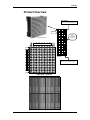
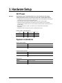
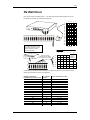
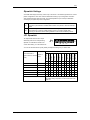
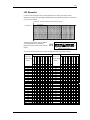
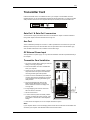
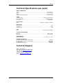
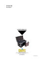
DVM-HR
DV Wall™
USER MANUAL
CHAUVET, 3000 N 29th Ct, Hollywood, FL 33020 U.S.A
(800) 762-1084 – (954) 929-1115
FAX (954) 929-5560
www.chauvetlighting.com
2007-02-05/16:45
Table of Contents
1. BEFORE YOU BEGIN....................................................................................................................................................... 3
UNPACKING INSTRUCTIONS.............................................................................................................................................................................................. 3
CONTACT US ................................................................................................................................................................................................................... 3
IMPORTANT SAFETY INFORMATION ................................................................................................................................................................................... 4
2. INTRODUCTION ............................................................................................................................................................... 5
OVERVIEW ...................................................................................................................................................................................................................... 5
FEATURES ....................................................................................................................................................................................................................... 5
COMPUTER SYSTEM REQUIREMENTS ............................................................................................................................................................................... 5
PRODUCT OVERVIEW....................................................................................................................................................................................................... 6
3. HARDWARE SETUP......................................................................................................................................................... 7
AC POWER ..................................................................................................................................................................................................................... 7
SYSTEM LIMITATIONS....................................................................................................................................................................................................... 7
MAXIMUM SYSTEM CONFIGURATION ................................................................................................................................................................................ 8
Other Configuration Examples................................................................................................................................................................................. 8
MOUNTING SYSTEM ......................................................................................................................................................................................................... 9
Flying bracket attachment...................................................................................................................................................................................... 10
SIGNAL & POWER CONFIGURATION ................................................................................................................................................................................ 11
DV-WALL DRIVER ......................................................................................................................................................................................................... 12
Dipswitch Settings.................................................................................................................................................................................................. 13
JP1 Dipswitch......................................................................................................................................................................................................... 13
JP2 Dipswitch......................................................................................................................................................................................................... 14
TRANSMITTER CARD ...................................................................................................................................................................................................... 15
Data Out 1 & Data Out 2 connectors..................................................................................................................................................................... 15
Aux Port ................................................................................................................................................................................................................. 15
DC External Power Input ....................................................................................................................................................................................... 15
Transmitter Card Installation.................................................................................................................................................................................. 15
EXAMPLE SYSTEM CONFIGURATIONS ............................................................................................................................................................................. 16
4:3 Aspect Ratio..................................................................................................................................................................................................... 16
4 meters by 3 meter ......................................................................................................................................................................................... 16
8 meters by 6 meters........................................................................................................................................................................................ 16
16 meters by 12 meters.................................................................................................................................................................................... 17
16:9 Aspect Ratio................................................................................................................................................................................................... 18
8 meters by 4.5 meters..................................................................................................................................................................................... 18
16 meters by 9 meters...................................................................................................................................................................................... 18
Special Applications............................................................................................................................................................................................... 19
Pattern 1 ........................................................................................................................................................................................................... 19
Pattern 2 ........................................................................................................................................................................................................... 19
4. APPENDIX....................................................................................................................................................................... 20
RETURNS PROCEDURE .................................................................................................................................................................................................. 20
CLAIMS ......................................................................................................................................................................................................................... 20
MAINTENANCE ............................................................................................................................................................................................................... 20
TECHNICAL SPECIFICATIONS (PER PANEL) ...................................................................................................................................................................... 21
TECHNICAL SUPPORT .................................................................................................................................................................................................... 21
©CHAUVET, 2006, All Rights Reserved
Information and specifications in this User Manual are subject to change without
notice. CHAUVET assumes no responsibility or liability for any errors or
inaccuracies that may appear in this manual.
DV Wall System User Manual
2
2007-02-05/16:45
1. Before You Begin
Unpacking Instructions
Immediately upon receiving a product, carefully unpack the carton, check the contents to ensure that
all parts are present, and have been received in good condition. Notify the shipper immediately and
retain packing material for inspection if any parts appear damaged from shipping or the carton itself
shows signs of mishandling. Save the carton and all packing materials. In the event that a fixture
must be returned to the factory, it is important that the fixture be returned in the original factory box
and packing.
If you should require sending any items back to CHAUVET, call CHAUVET for a
Note:
(RMA) Return Merchandise Authorization number. The factory will not allow any shipments without
an RMA.
Y o u r s h i p m e n t m a y i n c l u d e t h e f o l l ow i n g :
DV WALL SYSTEM
DV Wall LED Panel ......................................................................................................................... 4 pcs
Power Cables .................................................................................................................................. 4 pcs
Signal Cables .................................................................................................................................. 4 pcs
Mounting System............................................................................................................................. 4 pcs
User Manual & Warranty Card .................................................................................................................
DV WALL STUDIO (SOFTWARE)
Transmitter Card................................................................................................................................ 1 pc
DVI Signal Cable ............................................................................................................................... 1 pc
RS232 Signal Cable .......................................................................................................................... 1 pc
DV Wall Studio CD ROM................................................................................................................... 1 pc
Ethernet Cable................................................................................................................................... 1 pc
Signal Cable .................................................................................................................................... 8 pcs
DV Wall Driver (Video Receiver) ....................................................................................................... 1 pc
DV Wall Driver Power Supply............................................................................................................ 1 pc
Contact Us
World Wide
General Information
Chauvet Lighting
th
3000 North 29 Court
Hollywood, FL 33020
voice:
954.929.1115
fax:
954.929.5560
toll free: 800.762.1084
Technical Support
Chauvet Lighting
th
3000 North 29 Court
Hollywood, FL 33020
World Wide Web
DV Wall System User Manual
voice:
954.929.1115 (Press 4)
fax:
954.929.5560 (Attention: Service)
www.chauvetlighting.com
3
2007-02-05/16:45
Before You Begin
Important Safety Information
This product is designed for professional use. This product presents risks of lethal or severe injury
due to fire and heat, electric shock, and injury from falls. Read this manual before installing or
powering the fixture, follow the safety precautions listed below and observe all warnings in this
manual and on the fixture. If you have any questions about how to operate the fixture safely, please
contact CHAUVET.
Protection against Electric Shock
•
Always disconnect from AC power source before servicing or replacing LED clusters or fuse,
and be sure to replace with same type fuse.
•
All fixtures must be connected to circuits with a suitable Earth Ground.
•
Do not operate the fixture if covers are open or if any internal component is missing or damaged.
•
Make sure power cord is never crimped or damaged.
•
Never disconnect power cord by pulling or tugging on the cord.
Protection against Fire & Burns
•
Always make sure that you are connecting to the proper voltage and that the line voltage you are
connecting to is not higher than that stated on decal or rear panel of the fixture.
•
The unit must be installed in a location with adequate ventilation, at least 50cm from adjacent
surfaces. Be sure that no ventilation slots are blocked.
•
Maintain a minimum distance of 1 meter (3.28 feet) from combustible materials.
•
Allow this product to cool for a minimum of 15 minutes before opening, handling or removing the
cover in this product.
•
Maximum ambient temperature is Ta: 40°. Do not operate fixture at temperatures higher than
this.
Protection against Injury to persons
•
Secure fixture to fastening device using a safety chain.
•
Do not open fixture for a minimum of 15 minutes after switching off.
•
In the event of serious operating problem, stop using the unit immediately. Never try to repair the
unit by yourself. Repairs carried out by unskilled people can lead to damage or malfunction.
Please contact the nearest authorized technical assistance center. Always use the same type
spare parts.
DV Wall System User Manual
4
2007-02-05/16:45
2. Introduction
Overview
The DV Wall is both an indoor and outdoor LED video wall display suitable for a wide range of
applications. An IP65 rating ensures reliable and safe operation in most weather conditions. The DV
Wall can be seen comfortably during daytime or night time hours.
The DV Wall’s modular rugged design provides the user many shape and size building options. The
mounting system is easy and quick to assemble and disassemble. It is perfect for outdoor displays
and large viewing distances. The DV Wall is available in 31mm resolution providing the greatest
economy and value while maintaining optimum brightness.
Range of applications include but not limited to; Architectural, Merchandising & Retail, Rental &
Staging, Entertainment Venues, Sports Stadiums and Outdoor Advertising.
Features
•
•
•
•
•
•
•
•
•
•
Durable and weather resistant IP-65 rated housing
Mounting system has rigging points and flexible configurations
16.7 million colors (24bit)
Video/flash/text/RGB color mixing and any PC based graphics
Play music videos and DVDs from your computer
Additional power-con output for daisy chaining units together
Additional video output for daisy chaining units together
Works with other manufacturers’ software (must have DVI to DVW card installed)
Direct air convection cooled
Low power consumption
Requirements
•
•
•
•
DV Wall Driver (1 per every 6 panels wide and 16 panels high)
DV-Wall Studio software and/or ShowXpress Timeline (with DVI to DVW card
installed)
Windows XP computer with an available PCI slot
ATI graphics card
Computer System Requirements
EQUIPMENT
MINIMUM
RECOMMENDED
OPERATING SYSTEM
Windows XP SP2
Windows XP SP2
COMPUTER
Pentium 200 Mhz processor with at least
one free PCI slot
Pentium 1 Ghz or better with at
least one free PCI slot
MEMORY
128 MB
512MB or higher
HARD DISK
20 GB 5400 RPM
40 GB 7200 RPM or better
DISPLAY CARD
ATI Graphics Card with dual display and
DVI-I output
Note: NVIDIA graphics cards are not
compatible with this software
Tested on an ATI Radeon 9300
DV Wall System User Manual
5
2007-02-05/16:45
Introduction
Product Overview
Horizontal width:
6 panels or (96 vertical lines/columns)
1 Panel
1 Driver can
handle 6
panels wide by
16 panels high.
DV Wall 1024 Panel
Resolution: 16 horizontal lines/rows
Resolution: 16 vertical lines/columns
Maximum size matrix
using 1 driver
Vertical height:
16 panels or (256 horizontal lines/rows)
4 square panels = 1 square meter
DV Wall System User Manual
6
2007-02-05/16:45
3. Hardware Setup
AC Power
Warning!
Verify that the power requirement label on your unit matches the line voltage
applied. All fixtures must be connected to circuits with a suitable Earth Ground.
• To determine the power requirements for a particular fixture, see the label affixed to the back plate
of the fixture or refer to the fixture’s specifications chart.
• A fixture’s listed current rating is its average current draw under normal conditions.
• All fixtures must be powered directly off a switched circuit and cannot be run off a rheostat
(variable resistor) or dimmer circuit, even if the rheostat or dimmer channel is used solely for a 0%
to 100% switch.
• Before applying power to a fixture, check that the source voltage matches the fixture’s
requirement.
• All fixtures must be connected to circuits with a suitable Earth Ground.
P ow e r C a b l e C o n f i g u r a t i o n
CABLE
Pin
International
Screw Color
BROWN
Live
L
Yellow or Brass
BLUE
Neutral
N
Silver
YELLOW/GREEN
Earth
EG (Ground)
Green
System Limitations
VERTICAL PANELS (DOWN)
MINIMUM
1 panel = 16 rows of LED clusters or 16 vertical pixels/lines
MAXIMUM WITH 1 DRIVER
16 panels = 256 rows of LED clusters or 256 vertical pixels/lines
MAXIMUM WITH 2+ DRIVERS
32 panels = 512 rows of LED clusters or 512 vertical pixels
HORIZONTAL PANELS (ACROSS)
MINIMUM
1 panel = 16 columns of LED clusters or 16 horizontal pixels/lines
MAXIMUM WITH 1 DRIVER
6 panels = 96 columns of LED clusters or 96 horizontal pixels/lines
MAXIMUM WITH 2+ DRIVERS
48 panels = 768 columns of LED clusters or 768 horizontal pixels
RESOLUTION
MINIMUM
16 pixels X 16 pixels
MAXIMUM WITH 1 DRIVER
96 pixels X 128 pixels
MAXIMUM WITH 2+ DRIVERS
768 pixels X 512 pixels
DV Wall System User Manual
7
2007-02-05/16:45
Maximum System Configuration
(1) Driver can display 6 panels across
and 16 panels down (6 x 16)
8 meters
256 pixels
3 meters
1 2 3 4 5 6
2
3
4
5
6
7
8
9
10
11
12
13
14
15
16
17
18
19
20
21
22
23
24
25
26
27
28
29
30
31
32
96 pixels
7 8 9 10 11 12
13 14 15 16 17 18
19 20 21 22 23 24
25 26 27 28 29 30
31 32 33 34 35 36
37 38 39 40 41 42
43 44 45 46 47 48
D8
D7
D6
D5
D4
D3
D2
D1
D16
D15
D14
D13
D12
D11
D10
D9
Gaps between matrix sections are for visual aid only. Panel sections pair up edge to edge to maintain consistent pixel separation across multiple matrix sections.
Other Configuration Examples
1 2 3 4 5 6 7 8 9 10 11 12
2
3
4
5
6
7
7
8
8
9
9
10
10
11
12
13
13
14
14
15
15
16
16
D2
DV Wall System User Manual
D1
1 2 3 4 5 6 7 8 9 10 11 12
2
3
4
5
D3
D1
6
7
8
9
10
11
12
13
14
15
16
D2
8
2007-02-05/16:45
Setup
Mounting System
Each DV Wall panel comes with a square bracket with interlocking connectors that must first be
bolted to the two tracks located on opposite sides of the back of the panel using the provided M10
Hex bolts.
Affix the square
bracket to the back
of the DV Wall panel
using the provided
M10 Hex bolts.
M10M10
Hexagon
Hex Bolts Bolf
Each panel can be joined
together perfectly using the
positioning guides. The
interlocking connectors provide a
fast and safe method for building
and securing a large video
display area.
Easy interlocking system
DV Wall System User Manual
9
2007-02-05/16:45
Setup
Flying bracket attachment
The flying bracket attachment is used to fly or rig a 1 meter width section of a DV wall. It is designed
to be attached to the very top row of a 1 meter section. Additional hardware is provided for
interconnecting multiple flying brackets.
1
2
3
4
NOT FOR USE
ON SYSTEMS
LARGER THAN 6
METERS IN
HEIGHT!
ITEM
DESCRIPTION
1
Joining bracket
2
M10 Hex bolts
3
Hanging eye hook
4
Flying bracket
Caution!
•
Always make sure that all bolts are securely fastened.
•
For screens measuring 3 meters in height or beyond, use 2 rigging points for every 1 meter
section.
•
Do not use on systems larger than 6 meters in height.
DV Wall System User Manual
10
2007-02-05/16:45
Setup
Signal & Power Configuration
Net OUT1: displays the first 256 rows or
horizontal lines of the screens
Net OUT2: displays horizontal lines 257
through 512.
DRIVER 2
J16 J15 J14
J13 J12 J11 J10
J9 J8 J7 J6
J5 J4 J3 J2
J1
OUT
NEXT
DRIVER 1
DISPLAY CARD
VGA
DVI SIGNAL CABLE
RS232 SIGNAL CABLE
IN
COM
DVI
J16 J15 J14
J13 J12 J11 J10
J9 J8 J7 J6
J5 J4 J3 J2
J1
IN
DVI
1~256ROW
OUT 2
RJ-45
RJ-45
257~512ROW
OU T 1
TRANSMITTER
SIGNAL CABLE
OUT
NET CABLE
Multiple drivers are used for larger
video displays and patterns.
Each DV Wall panel
consumes 109W of
power.
Signal IN
Power IN
Power OUT Signal OUT
Signal IN
Power IN
Power OUT Signal OUT
NEXT
AC: 110V/ 230V...50/ 60Hz
NEXT
No more than 20 panels should be
connected to a 20 amp circuit on
110V power or 40 panels on 230V.
Obtain additional circuits accordingly.
Signal IN
Power IN
Power OUT Signal OUT
Signal IN
Power IN
Power OUT Signal OUT
NEXT
AC: 110V/ 230V...50/ 60Hz
NEXT
REAR VIEW
DV Wall System User Manual
11
2007-02-05/16:45
Setup
DV-Wall Driver
Every driver contains 16 output ports (J1 ~ J16). Each output port provides signal source to one
horizontal row of panels not exceeding 6 panels wide.
1
J1 6
J15
J14
J13
J12
J1 1
SIGNAL
J10
J9
J8
J7
J6
POWERIN
IN
J5
J4
J3
J2
J1
OUT
J3
J16 J15 J14
J13 J12
J11
J10
J9
J8
J7
J2
J6
J1
J5
J4
J3
J2
J1
Example
If an application called for a video
wall 3 meters high and 3 meters
wide the following connection
diagram would apply:
J14
J13
J12 J11 J10
J9
J8
J7
J6
J5
IN
J4
J3
J2
Each J connector
corresponds to a specific
row number on the matrix.
J1
OUT
3
4
6
5
Rear View
1
J16 J15
2
J1
J2
J3
J4
J5
J6
J7
J8
J9
J10
J11
J12
J13
J14
J15
J16
2
3
J1
4
5
6
2x2
panels =
1 meter²
J2
J3
J4
J9
J8
J7
J6
J5
J4
J3
J2
J1
J5
J6
Rear View
It is also easy to calculate a required number of J output connectors to use so long as you have a
specific pixel resolution in mind for your application.
NUMBER OF HORIZONTAL
NO. OF PANELS
LINES(ROWS) OR VERTICAL PIXELS VERTICAL
16
32
48
64
80
96
112
128
144
160
176
192
208
224
240
256
DV Wall System User Manual
1
2
3
4
5
6
7
8
9
10
11
12
13
14
15
16
OUTPUT CONNECTIONS TO USE
J1
J1 ~ J2
J1 ~ J3
J1 ~ J4
J1 ~ J5
J1 ~ J6
J1 ~ J7
J1 ~ J8
J1 ~ J9
J1 ~ J10
J1 ~ J11
J1 ~ J12
J1 ~ J13
J1 ~ J14
J1 ~ J15
J1 ~ J16
12
2007-02-05/16:45
Setup
Dipswitch Settings
A DV-Wall video display matrix may consist of up to 16 drivers or 16 individual grid sections in various
pattern configurations. Each driver must be addressed according to your configuration so that the
video displayed appears whole and intact. Two internal dipswitches (JP1 & JP2) are addressed
according to your system layout and configuration.
JP1
Sets the total width one driver will display. The width can be described in either number
of panels or pixel resolution. Possible widths include 1 to 6 panels or 16 to 96 horizontal
pixels.
JP2
Sets the starting vertical line from which this driver will begin to display video. Remember
that a matrix may consist of multiple sections across, so in order to display video
correctly you will need to set the starting address for each section handled by a driver.
JP1 Dipswitch
JP1 dipswitches have their own unique
1
JP1
addressing method. For example setting
dipswitch 3 to ON adds 32 values to the
2
3
4
5
6
7
8
9 10 11 12
ON
OFF
W32
W128
W64
counter while setting 11 to ON subtracts 16.
W256
-W16
W512
W1024
DEFAULT SETTING = 32
You can use the table below to quickly identify the dipswitch settings for your matrix width.
add 128
add 256
add 512
add 1024
(Default Off)
(Default Off)
subtract 16
(Default Off)
panels
add 64
lines)
Number of
add 32
(pixel columns or vertical
(Default On)
Horizontal Width in
(Default Off)
JP1 Dipswitches
2
3
4
5
6
7
8
9
10
11
12
1
16
1
1
1
32
2
1
48
3
1
1
64
4
1
1
80
5
1
1
96
6
1
1
1
1
Note: 1 = Dipswitch ON, Blank = Dipswitch OFF
The default setting of dipswitch # 2 ON and all others OFF
equals 32.
DV Wall System User Manual
13
2007-02-05/16:45
Setup
JP2 Dipswitch
In order for video to display properly across multiple sections or drivers, each driver must be
addressed accordingly. The JP2 dipswitch establishes the horizontal starting address or (vertical line)
for each section of matrix.
Vertical Line, JP2 set @ 0 (default) (horizontal starting address)
16 lines/pixels
Horizontal Line
Just like the JP1 dipswitch, JP2 has different
JP2
numerical designations for addressing.
Dipswitches 6 and 7 always remain in the ON
1
2
3
5
6
7
8
9 10 11 12
ON
OFF
S64
S256
S128
position.
4
S32 S16
S512
DEFAULT START ADDR = 0
You can use the table below to quickly identify the dipswitch settings for a starting address.
address)
1 2 3 4 5 6 7 8 9 10 11
0
1 1
16
1 1
1
32
1 1
48
1 1
1
64
1
1 1
80
1
1 1
1
96
1
1 1
112
1
1 1
1
128
1
1 1
144
1
1 1
1
160
1
1 1
176
1
1 1
1
192
1 1
1 1
208
1 1
1 1
1
224
1 1
1 1
240
1 1
1 1
1
256
1
1 1
272
1
1 1
1
288
1
1 1
304
1
1 1
1
320
1
1
1 1
336
1
1
1 1
1
352
1
1
1 1
368
1
1
1 1
1
384
1 1
1 1
Note: 1 = Dipswitch ON, Blank = Dipswitch OFF
DV Wall System User Manual
14
Vertical Lines
(Horizontal starting
address)
12
1
1
1
1
1
1
1
1
1
1
1
1
400
416
432
448
464
480
496
512
528
544
560
576
592
608
624
640
656
672
688
704
720
736
752
768
add 64
add 128
add 256
add 512
(Default Off)
(Default On)
(Default On)
(Default Off)
(Default Off)
(Default Off)
add 16
add 32
Vertical Lines
(Horizontal starting
JP2 Dipswitches
add 64
add 128
add 256
add 512
(Default Off)
(Default On)
(Default On)
(Default Off)
(Default Off)
(Default Off)
add 16
add 32
JP2 Dipswitches
1 2
1
1
1
1 1
1 1
1 1
1 1
1
1
1
1
1
1
1
1
1
1
1
1
1
1
1
1
3 4 5 6 7 8 9 10 11 12
1
1 1
1
1
1 1
1
1
1 1
1 1
1
1 1
1
1 1
1
1
1 1
1
1
1 1
1 1
1
1 1
1
1 1
1
1
1 1
1
1
1 1
1 1
1
1 1
1
1 1
1
1
1 1
1
1
1 1
1 1
1
1 1
1
1 1
1
1
1 1
1
1
1 1
1 1
1
1 1
1
1 1
1
1
1 1
1
1
1 1
1 1
1 1
1 1
2007-02-05/16:45
Setup
Transmitter Card
Install the transmitter card in an available PCI slot in your computer. The transmitter card is the
interface between your PC, DV-Wall Studio software and the DV-Wall Screen. You must use the DVI
cable provided to connect from the computers DVI output to the DVI port on the transmitter card.
DVI Port
Aux port
DC external
power input
RJ-45
RJ-45
Data Out 2
Data Out 1
Data Out 1 & Data Out 2 connectors
The two network output ports transmit 256 rows or horizontal lines. Output 1 transmits rows/lines 1
through 256. Output 2 transmits rows/lines 257 through 512.
Aux Port
This is a standard 6-pin telephone connector. A cable is provided that connects from the 9-pin DIN
RS232 port to the Aux port on the transmitter card. This port allows control of the R variable, gray
scale, DV Wall matrix active area, and matrix lock and matrix range.
DC External Power Input
This input takes a 5V power supply. It is only used if the transmitter card will be operated eternally of
the computer.
Transmitter Card Installation
1. Turn off the computer before opening its case and
adding or removing components.
2. Insert the transmitter card into an available PCI
slot in your computer.
3. Connect out of your computer’s display card DVI
output and into the DVI input on the transmitter
card using the DVI signal cable provided.
6. If using displaying 512 row lines connect the
OUT 2 as well to a new driver.
COM
DISPLAY CARD
VGA
DVI SIGNAL CABLE
5. Plug the provided ethernet cable into the
RJ45 connector labeled OUT 1 and into a
driver’s etherbet IN connector to display rows
1 through 256.
RS232 SIGNAL CABLE
4. Connect out of the serial RS232 (also COM port)
connector and into the 6-pin telephone connector
on the transmitter card using the RS232 signal
cable provided.
DVI
DVI
1~256ROW
NETCABLE
OUT 2
RJ-45
RJ-45
OUT1
7. Secure all connections.
8. In order to test the system successfully it will be
necessary to address the drivers correctly. Jump
to the section in this manual on driver dipswitch
settings.
257~512ROW
TRANSMITTER
9. Once drivers are assigned, turn on the computer and test the system.
Note!
If your computer reboots or turns off abruptly; please remove the DVI cable from the transmitter card
and reboot your computer. After Windows loads reconnect the DVI cable.
DV Wall System User Manual
15
2007-02-05/16:45
Setup
Example System Configurations
4:3 Aspect Ratio
4 meters by 3 meter
96 pixels wide or
96 vertical lines
Front View
32 pixels wide or
32 vertical lines
Driver J output ports
System Information
Vertical lines: 128
Horizontal lines: 96
Resolution: 128 x 96 pix
Size: 4m x 3m
Panels: 48 (8 x 6)
Power: 3 x 20A (110V)
Drivers: 2
Ethernet Out: Out 1
J Ports: 1 ~ 6
Driver 1
J1
J1
J2
J2
J3
J3
J4
J4
Driver 2
J5
J5
J6
J6
Starting Address: 0
Width = 32
JP1
1 2 3 4 5 6 7 8 9 10 11 12
0 1 0 0 0 0 0 0 0 0 0 0
Start = 96
JP2
1 2 3 4 5 6 7 8 9 10 11 12
1 0 0 0 0 1 1 0 0 0 0 1
Width = 96
JP1
1 2 3 4 5 6 7 8 9 10 11 12
0 1 0 1 0 0 0 0 0 0 0 0
Start = 0
JP2
1 2 3 4 5 6 7 8 9 10 11 12
0 0 0 0 0 1 1 0 0 0 0 0
Starting Address: 96
Driver 2
Driver 1
8 meters by 6 meters
Front View
256 pixels wide or
256 vertical lines
96 pixels wide or
96 vertical lines
System Information
Vertical lines: 256
Horizontal lines: 192
Resolution: 256 x 192 pix
Size: 8m x 6m
Panels: 192 (16 x 12)
Power: 10 x 20A (110V)
Drivers: 3
Net Out: Out 1
J Ports: 1 ~ 12
96 pixels wide or
96 vertical lines
64 pixels wide or
64 vertical lines
J1
J1
J1
J2
J2
J2
J3
J3
J3
J4
J4
J4
J5
J5
J5
J6
J6
J6
J7
J7
J7
J8
J8
J8
J9
J9
J9
J10
J10
J10
J11
J11
J11
J12
J12
J12
Starting Address: 0
Starting Address: 96
Driver 3
Starting Address: 192
Driver 2
Driver 1
Driver 1
Driver 2
Width = 64
JP1
1 2 3 4 5 6 7 8 9 10 11 12
0 1 1 0 0 0 0 0 0 0 0 0
Width = 96
JP1
1 2 3 4 5 6 7 8 9 10 11 12
0 1 0 1 0 0 0 0 0 0 0 0
Start = 192
JP2
1 2 3 4 5 6 7 8 9 10 11 12
1 1 0 0 0 1 1 0 0 0 0 0
Start = 96
JP2
1 2 3 4 5 6 7 8 9 10 11 12
1 0 0 0 0 1 1 0 0 0 0 1
Width = 96
JP1
1 2 3 4 5 6 7 8 9 10 11 12
0 1 0 1 0 0 0 0 0 0 0 0
Start = 0
JP2
1 2 3 4 5 6 7 8 9 10 11 12
0 0 0 0 0 1 1 0 0 0 0 0
Driver 3
DV Wall System User Manual
16
2007-02-05/16:45
Setup
16 meters by 12 meters
Transmitter Card
Width
96 pixels/lines
RJ-45
RJ-45
Net OUT1
outputs lines
0 ~ 256
96 pixels/lines
96 pixels/lines
96 pixels/lines
96 pixels/lines
32 pixels/lines
J1
J1
J1
J1
J1
J1
J2
J2
J2
J2
J2
J2
J3
J3
J3
J3
J3
J3
J4
J4
J4
J4
J4
J4
J5
J5
J5
J5
J5
J5
J6
J6
J6
J6
J6
J6
J7
J7
J7
J7
J7
J7
J8
J8
J8
J8
J8
J8
J9
J9
Front ViewJ9
J9
J9
J9
J10
J10
J10
J10
J10
J10
J11
J11
J11
J11
J11
J11
J12
J12
J12
J12
J12
J12
J13
J13
J13
J13
J13
J13
J14
J14
J14
J14
J14
J14
J15
J15
J15
J15
J15
J15
J16
J16
J16
J16
J16
J16
Driver 6
Driver 5
Driver 4
Driver 3
Driver 2
Driver 1
J1
J1
J1
J1
J1
J1
J2
J2
J2
J2
J2
J2
J3
J3
J3
J3
J3
J3
J4
J4
J4
J4
J4
J4
J5
J5
J5
J5
J5
J5
System Information
J6
J6
J6
J6
J6
J6
Vertical lines: 512
Horizontal lines: 384
Resolution: 512 x 384 pix
Size: 16m x 12m
Panels: 768 (32 x 24)
Power: 39 x 20A (110V)
Drivers: 12
Net Out: Out1 & Out2
J Ports: Out1: J1 ~ J16
J Ports: Out2: J1 ~ J8
J7
J7
J7
J7
J7
J7
J8
J8
J8
J8
J8
Net OUT2 outputs lines
257 ~ 512
Driver 12
Driver 11
Starting
Address: 0
Driver 10
Starting
Address: 96
Driver 9
Starting
Address: 192
Starting
Address: 288
Starting
Address: 384
J8
Driver 7
Starting
Address: 480
Driver 7
Driver 1
Width = 32
JP1
1 2 3 4 5 6 7 8 9 10 11 12
0 1 0 0 0 0 0 0 0 0 0 0
Width = 32
JP1
1 2 3 4 5 6 7 8 9 10 11 12
0 1 0 0 0 0 0 0 0 0 0 0
Start = 480
JP2
1 2 3 4 5 6 7 8 9 10 11 12
1 1 1 0 0 1 1 0 0 0 0 1
Start = 480
JP2
1 2 3 4 5 6 7 8 9 10 11 12
1 1 1 0 0 1 1 0 0 0 0 1
Width = 96
JP1
1 2 3 4 5 6 7 8 9 10 11 12
0 1 0 1 0 0 0 0 0 0 0 0
Width = 96
JP1
1 2 3 4 5 6 7 8 9 10 11 12
0 1 0 1 0 0 0 0 0 0 0 0
Start = 384
JP2
1 2 3 4 5 6 7 8 9 10 11 12
0 1 1 0 0 1 1 0 0 0 0 0
Start = 384
JP2
1 2 3 4 5 6 7 8 9 10 11 12
0 1 1 0 0 1 1 0 0 0 0 0
JP1
1 2 3 4 5 6 7 8 9 10 11 12
0 1 0 1 0 0 0 0 0 0 0 0
Width = 96
JP1
1 2 3 4 5 6 7 8 9 10 11 12
0 1 0 1 0 0 0 0 0 0 0 0
JP2
1 2 3 4 5 6 7 8 9 10 11 12
0 0 0 0 0 1 1 0 0 0 0 1
Start = 288
JP2
1 2 3 4 5 6 7 8 9 10 11 12
0 0 0 0 0 1 1 0 0 0 0 1
Width = 96
JP1
1 2 3 4 5 6 7 8 9 10 11 12
0 1 0 1 0 0 0 0 0 0 0 0
Start = 192
JP2
1 2 3 4 5 6 7 8 9 10 11 12
1 1 0 0 0 1 1 0 0 0 0 0
Driver 2
Driver 8
Driver 3
Width = 96
Start = 288
Ethernet OUT1
outputs horizontal
lines
0 ~ 256
Driver 8
Driver 9
Driver 4
Ethernet OUT2
outputs horizontal
lines
257 ~ 512
Driver 10
JP1
1 2 3 4 5 6 7 8 9 10 11 12
0 1 0 1 0 0 0 0 0 0 0 0
JP2
1 2 3 4 5 6 7 8 9 10 11 12
1 1 0 0 0 1 1 0 0 0 0 0
Width = 96
JP1
1 2 3 4 5 6 7 8 9 10 11 12
0 1 0 1 0 0 0 0 0 0 0 0
Width = 96
JP1
1 2 3 4 5 6 7 8 9 10 11 12
0 1 0 1 0 0 0 0 0 0 0 0
Start = 96
JP2
1 2 3 4 5 6 7 8 9 10 11 12
1 0 0 0 0 1 1 0 0 0 0 1
Start = 96
JP2
1 2 3 4 5 6 7 8 9 10 11 12
1 0 0 0 0 1 1 0 0 0 0 1
Width = 96
JP1
1 2 3 4 5 6 7 8 9 10 11 12
0 1 0 1 0 0 0 0 0 0 0 0
Width = 96
JP1
1 2 3 4 5 6 7 8 9 10 11 12
0 1 0 1 0 0 0 0 0 0 0 0
Start = 0
JP2
1 2 3 4 5 6 7 8 9 10 11 12
0 0 0 0 0 1 1 0 0 0 0 0
Start = 0
JP2
1 2 3 4 5 6 7 8 9 10 11 12
0 0 0 0 0 1 1 0 0 0 0 0
Width = 96
Start = 192
Driver 5
Driver 11
Driver 6
DV Wall System User Manual
Driver 12
17
2007-02-05/16:45
Setup
16:9 Aspect Ratio
8 meters by 4.5 meters
Front View
256 pixels wide or
256 vertical lines
96 pixels wide or
96 vertical lines
System Information
Vertical lines: 256
Horizontal lines: 144
Resolution: 256 x 144 pix
Size: 8m x 4.5m
Panels: 144 (16 x 9)
Power: 8 x 20A (110V)
Drivers: 3
Net Out: Out 1
J Ports: 1 ~ 9
96 pixels wide or
96 vertical lines
64 pixels wide or
64 vertical lines
J1
J1
J1
J2
J2
J2
J3
J3
J3
J4
J4
J4
J5
J5
J5
J6
J6
J6
J7
J7
J7
J8
J8
J8
J9
J9
J9
Starting Address: 0
Starting Address: 96
Driver 3
Starting Address: 192
Driver 2
Driver 1
Driver 1
Driver 2
Width = 64
JP1
1 2 3 4 5 6 7 8 9 10 11 12
0 1 1 0 0 0 0 0 0 0 0 0
Width = 96
JP1
1 2 3 4 5 6 7 8 9 10 11 12
0 1 0 1 0 0 0 0 0 0 0 0
Start = 192
JP2
1 2 3 4 5 6 7 8 9 10 11 12
1 1 0 0 0 1 1 0 0 0 0 0
Start = 96
JP2
1 2 3 4 5 6 7 8 9 10 11 12
1 0 0 0 0 1 1 0 0 0 0 1
Width = 96
JP1
1 2 3 4 5 6 7 8 9 10 11 12
0 1 0 1 0 0 0 0 0 0 0 0
Start = 0
JP2
1 2 3 4 5 6 7 8 9 10 11 12
0 0 0 0 0 1 1 0 0 0 0 0
Driver 3
16 meters by 9 meters
By now you should have a good understanding of the steps involved in configuring fairly simple sizes.
The following example will not illustrate the grid but will present all dipswitch settings in a table format
and relevant system information for a 16 by 9 meter matrix. J1~J8 are used for Net OUT2 only.
Driver
Driver
JP1
1 2 3 4 5 6 7 8 9 10 11 12
0 1 0 0 0 0 0 0 0 0 0 0
Start = 192
JP2
1 2 3 4 5 6 7 8 9 10 11 12
1 1 1 0 0 1 1 0 0 0 0 1
Width = 64
JP1
1 2 3 4 5 6 7 8 9 10 11 12
0 1 0 1 0 0 0 0 0 0 0 0
Width = 64
1
2
Start = 192
Width = 64
JP2
1 2 3 4 5 6 7 8 9 10 11 12
0 1 1 0 0 1 1 0 0 0 0 0
JP1
1 2 3 4 5 6 7 8 9 10 11 12
0 1 0 1 0 0 0 0 0 0 0 0
3
Start = 192
JP2
1 2 3 4 5 6 7 8 9 10 11 12
0 0 0 0 0 1 1 0 0 0 0 1
Width = 64
JP1
1 2 3 4 5 6 7 8 9 10 11 12
0 1 0 1 0 0 0 0 0 0 0 0
4
Start = 192
Width = 64
JP2
1 2 3 4 5 6 7 8 9 10 11 12
1 1 0 0 0 1 1 0 0 0 0 0
JP1
1 2 3 4 5 6 7 8 9 10 11 12
0 1 0 1 0 0 0 0 0 0 0 0
5
Start = 192
JP2
1 2 3 4 5 6 7 8 9 10 11 12
1 0 0 0 0 1 1 0 0 0 0 1
Width = 64
JP1
1 2 3 4 5 6 7 8 9 10 11 12
0 1 0 1 0 0 0 0 0 0 0 0
JP2
1 2 3 4 5 6 7 8 9 10 11 12
0 0 0 0 0 1 1 0 0 0 0 0
6
Start = 192
Width = 64
JP1
1 2 3 4 5 6 7 8 9 10 11 12
0 1 0 0 0 0 0 0 0 0 0 0
Start = 192
JP2
1 2 3 4 5 6 7 8 9 10 11 12
1 1 1 0 0 1 1 0 0 0 0 1
Width = 64
JP1
1 2 3 4 5 6 7 8 9 10 11 12
0 1 0 1 0 0 0 0 0 0 0 0
Start = 192
JP2
1 2 3 4 5 6 7 8 9 10 11 12
0 1 1 0 0 1 1 0 0 0 0 0
Width = 64
JP1
1 2 3 4 5 6 7 8 9 10 11 12
0 1 0 1 0 0 0 0 0 0 0 0
Start = 192
JP2
1 2 3 4 5 6 7 8 9 10 11 12
0 0 0 0 0 1 1 0 0 0 0 1
Width = 64
JP1
1 2 3 4 5 6 7 8 9 10 11 12
0 1 0 1 0 0 0 0 0 0 0 0
Start = 192
JP2
1 2 3 4 5 6 7 8 9 10 11 12
1 1 0 0 0 1 1 0 0 0 0 0
Width = 64
JP1
1 2 3 4 5 6 7 8 9 10 11 12
0 1 0 1 0 0 0 0 0 0 0 0
Start = 192
JP2
1 2 3 4 5 6 7 8 9 10 11 12
1 0 0 0 0 1 1 0 0 0 0 1
Width = 64
JP1
1 2 3 4 5 6 7 8 9 10 11 12
0 1 0 1 0 0 0 0 0 0 0 0
Start = 192
JP2
1 2 3 4 5 6 7 8 9 10 11 12
0 0 0 0 0 1 1 0 0 0 0 0
7
8
9
10
11
12
System Information
Vertical lines: 512
Horizontal lines: 384
Resolution: 512 x 384 pix
Size: 16m x 9m
Panels: 768 (32 x 24)
DV Wall System User Manual
Power: 96 x 20A (110V)
Drivers: 12
Net Out: Out1 & Out2
J Ports: Out1: J1 ~ J16
J Ports: Out2: J1 ~ J8
18
2007-02-05/16:45
Setup
Special Applications
Pattern 1
System Information
Vertical lines: 208
Horizontal lines: 96
Resolution: 208 x 96 pix
Size: 6.5m x 3m
Panels: 52 (pattern)
Power: 3 x 20A (110V)
Drivers: 4
Net Out: Out 1
J Ports: 1 ~ 6
D3
D4
This space is optional. You
may choose to have the
video signal displayed
continuously regardless of
the gap.
64p
64p
48p
32p
J1
J1
J1
J2
J2
J2
J3
J3
J3
J4
J4
J4
J5
D2
J5
J6
Starting
Addr: 0
D1
J6
Starting
Addr: 64
Starting
Addr: 128
Starting
Addr: 176
Driver
Width = 32
JP1
1 2 3 4 5 6 7 8 9 10 11 12
0 1 0 0 0 0 0 0 0 0 0 0
Start = 176
JP2
1 2 3 4 5 6 7 8 9 10 11 12
1 1 1 0 0 1 1 0 0 0 0 1
Width = 48
JP1
1 2 3 4 5 6 7 8 9 10 11 12
0 1 0 1 0 0 0 0 0 0 0 0
Start = 128
JP2
1 2 3 4 5 6 7 8 9 10 11 12
0 1 1 0 0 1 1 0 0 0 0 0
Width = 64
JP1
1 2 3 4 5 6 7 8 9 10 11 12
0 1 0 1 0 0 0 0 0 0 0 0
Start = 64
JP2
1 2 3 4 5 6 7 8 9 10 11 12
0 0 0 0 0 1 1 0 0 0 0 1
Width = 64
JP1
1 2 3 4 5 6 7 8 9 10 11 12
0 1 0 1 0 0 0 0 0 0 0 0
Start = 0
JP2
1 2 3 4 5 6 7 8 9 10 11 12
1 1 0 0 0 1 1 0 0 0 0 0
1
2
3
4
Pattern 2
System Information
32p
32p
Vertical lines: 96
Horizontal lines: 96
Resolution: 96 x 96 pix
Size: 3m x 3m
Panels: 20 (pattern)
Power: 1 x 20A (110V)
Drivers: 3
Net Out: Out 1
J Ports: 1 ~ 5
32p
J1
J1
J2
J2
J2
J3
J4
J4
J5
J5
Starting
Addr: 0
Starting
Addr: 64
D1
D3
Starting
Addr: 32
D2
Driver
Width = 32
JP1
1 2 3 4 5 6 7 8 9 10 11 12
0 1 0 0 0 0 0 0 0 0 0 0
Start = 176
JP2
1 2 3 4 5 6 7 8 9 10 11 12
1 1 1 0 0 1 1 0 0 0 0 1
Width = 48
JP1
1 2 3 4 5 6 7 8 9 10 11 12
0 1 0 1 0 0 0 0 0 0 0 0
Start = 128
JP2
1 2 3 4 5 6 7 8 9 10 11 12
0 1 1 0 0 1 1 0 0 0 0 0
Width = 64
JP1
1 2 3 4 5 6 7 8 9 10 11 12
0 1 0 1 0 0 0 0 0 0 0 0
Start = 64
JP2
1 2 3 4 5 6 7 8 9 10 11 12
0 0 0 0 0 1 1 0 0 0 0 1
1
2
3
a
DV Wall System User Manual
19
2007-02-05/16:45
4. Appendix
Returns Procedure
Returned merchandise must be sent prepaid and in the original packing, call tags will not be issued.
Package must be clearly labeled with a Return Merchandise Authorization Number (RA #). Products
returned without an RA # will be refused. Call CHAUVET and request RA # prior to shipping the
fixture. Be prepared to provide the model number, serial number and a brief description of the cause
for the return. Be sure to properly pack fixture, any shipping damage resulting from inadequate
packaging is the customer’s responsibility. CHAUVET reserves the right to use its own discretion to
repair or replace product(s). As a suggestion, proper UPS packing or double-boxing is always a safe
method to use.
Claims
Damage incurred in shipping is the responsibility of the shipper; therefore the damage must be
reported to the carrier upon receipt of merchandise. It is the customer's responsibility to notify and
submit claims with the shipper in the event that a fixture is damaged due to shipping. Any other claim
for items such as missing component/part, damage not related to shipping, and concealed damage,
must be made within seven (7) days of receiving merchandise.
Maintenance
To maintain optimum performance and minimize wear, fixtures should be cleaned frequently. Usage
and environment are contributing factors in determining frequency. As a general rule, fixtures should
be cleaned at least twice a month. Dust build up reduces light output performance and can cause
overheating. This can lead to reduced lamp life and increased mechanical wear. Be sure to power off
fixture before conducting maintenance.
Unplug fixture from power. Use a vacuum or air compressor and a soft brush to remove dust
collected on external vents and internal components. Clean all glass when the fixture is cold with a
mild solution of glass cleaner or Isopropyl Alcohol and a soft lint free cotton cloth or lens tissue. Apply
solution to the cloth or tissue and drag dirt and grime to the outside of the lens. Gently polish optical
surfaces until they are free of haze and lint. Do not to touch the lamp glass when cleaning fixture. Oil
and dirt can cause damage and premature aging of the lamp. In the event that the lamp is touched or
becomes dirty, clean the lamps with an alcohol wipe.
The cleaning of internal and external optical lenses and/or mirrors must be carried out periodically to
optimize light output. Cleaning frequency depends on the environment in which the fixture operates:
damp, smoky or particularly dirty surrounding can cause greater accumulation of dirt on the unit’s
optics. Clean with soft cloth using normal glass cleaning fluid. - Always dry the parts carefully. - Clean
the external optics at least every 20 days. Clean the internal optics at least every 30/60 days.
DV Wall System User Manual
20
2007-02-05/16:45
Appendix
Technical Specifications (per panel)
WEIGHT & DIMENSIONS
Length........................................................................................................................... 19.8 in (501 mm)
Width ............................................................................................................................ 19.8 in (501 mm)
Height ............................................................................................................................. 4.0 in (101 mm)
Weight with mounting hardware ...................................................................................... 28 lbs (12.7 kg)
POWER
Operating Voltage .........................................................................................110V 60 Hz or 230V 50 Hz
Power consumption ................................................................................................. 109W peak @ 120V
Inrush power..................................................................................................................... 136W @ 120V
LIGHT SOURCE
LED’s .............................................................................................. 2304 (768 red, 768 green, 768 blue)
PHOTO OPTIC
Viewing Angle................................................................................................................................... 120°
Pixel Pitch.......................................................................................................................................31mm
Pixels per panel ..................................................................................................................................256
FUSE
Main............................................................................................................... 20mm Glass 8A Fast Blow
CONTROL & PROGRAMMING
Data input ........................................................................................................................ VGA connector
Data output ...................................................................................................................... VGA connector
ENVIRONMENTAL
Ambient temperature .......................................................................................14° – 104°F (-10° – 40°C)
ORDERING INFORMATION
DV Wall™ Panel Set (4 panels in flight case) ........................................................................... DVM-HR
DV Wall™ Studio (software, PCI card, cables) .................................................................... DVW Studio
DV Wall™ Driver ...................................................................................................................DVW Driver
Flying Bracket for DVM-HR ........................................................................................................DVM-BR
Technical Support
Address: Service Dept.
3000 N 29th Ct, Hollywood, FL 33020 (U.S.A.)
Support (Email): [email protected]
Telephone: (954) 929-1115 - (Press 4)
Fax: (954) 929-5560 - (Attention: Service)
Website: http://www.chauvetlighting.com
DV Wall System User Manual
21
2007-02-05/16:45