1
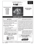
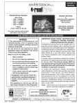
Owner’s
Manual
Woodland Oak (WOG4-24) Shown
G4/GX4 SERIES BURNER
Important: Read these instructions carefully before
starting installation of the gas log set.
WARNING
If the information in this manual is not followed
exactly, a fire or explosion may result, causing
property damage, personal injury, or loss of life.
This burner system is to be installed only in a solid-fuelburning fireplace with a working flue and constructed
of noncombustible material. Solid fuels shall not be
burned in a fireplace where this gas log set is installed.
The installation, including provisions for combustion,
ventilation air, and required minimum permanent vent
opening, must conform with the National Fuel Gas
Code (Z223.1) and applicable local building codes. A
damper stop clamp is included to maintain the minimum
permanent vent opening and to prevent full closure of
the damper blade. The chimney damper should be
fully opened when burning the log set. The log set is
designed to burn with yellow flames; thus, adequate
ventilation is absolutely necessary.
Do not store or use gasoline or other flammable
vapors and liquids in the vicinity of this or any
other appliance.
WHAT TO DO IF YOU SMELL GAS:
• Open a window.
• Do not try to light any appliance.
• Do not touch any electrical switch; do not
use any phone in the building.
• Immediately call the gas supplier from
a neighbor’s phone and follow the gas
supplier’s instructions.
• If you cannot reach the gas supplier, call the
fire department.
Installation and service must be performed
by an NFI Certified or other qualified
professional installer, service agency, or
the gas supplier.
Important: To comply with certification, listings, and
building code acceptance, and for safe
operation and proper performance,
ONLY Peterson parts and accessories
may be used with this gas log set.
INSTALLER & CONSUMER
These instructions MUST be retained
with this appliance.
We recommend that our gas
hearth products be installed
and serviced by professionals
who are certified in the U.S.
by the National Fireplace
Institute® (NFI) as NFI Gas
Specialists.
ROBERT H. PETERSON CO. • 14724 East Proctor Avenue • City of Industry, CA 91746
REV 4 - 0907131103
1
No. L-A2-01309
IMPORTANT - Read This Manual Carefully Before Starting Installation of the Log Set
When the log set is burning, the fireplace
damper must be fully open. The Peterson RealFyre® gas log set is to be burned only in a fully
vented, noncombustible fireplace with damper and
chimney free of any obstructions. The fireplace
must be designed and approved to burn wood. As
with burning natural firewood, the Real-Fyre® log
set is designed to burn with yellow, smoky flames.
For this reason, it must be adequately vented. The
smallest dimension of the chimney flue must be at
least 8". If it is smaller, do not use this Real-Fyre®
log set. If fumes from the burner emerge into the
room when the damper is fully open, creating a
smell like a smoldering oil lamp, it indicates that
the fireplace draft is defective. Check chimney flue
for obstructions. Do not operate the log set until
the fireplace draft is corrected. Check with the
dealer or installer. Do not use firewood with the
gas log set.
Some Available Log Styles:
Charred Series
Charred Oak (CHD)
Charred Split (CHS)
Charred Royal (CHB)
Classic Series
Golden Oak (R)
Post Oak (PO)
Emberwood (E)
Royal English Oak (B)
Mountain Oak (K)
Twisted Pine (C)
Designer Series
Golden Oak Designer Plus
(RDP)
Split Oak (S)
Split Oak Designer Plus
(SDP)
Woodland Oak (WO)
Designer (EXD)
Royal English Oak
Designer (BD)
Heritage Designer (HD)
White Birch (W)
Golden Oak Designer (RD6)
FOR YOUR SAFETY
Do not store or use gasoline or other flammable
vapors and liquids in the vicinity of this or any other
appliance.
TABLE OF CONTENTS
PARTS LIST
FIREPLACE REQUIREMENTS
INSTALLING THE BURNER SYSTEM
INSTALLING THE DAMPER CLAMP
INSTALLING THE BURNER SYSTEM (Cont.)
PLACEMENT OF GRATE AND BURNER
CONNECTING THE GAS SUPPLY
INSTALLING THE BURNER SYSTEM (Cont.)
INSTALLING THE BURNER SYSTEM (Cont.)
INSTALLING THE BURNER SYSTEM (Cont.)
PLACEMENT OF GRANULES, GLOWING EMBERS AND GRATE
GRANULE PLACEMENT
GLOWING EMBERS PLACEMENT
GRATE REPLACEMENT
GAS LOG PLACEMENT
DESIGNER AND CLASSIC SERIES LOG PLACEMENT
CHARRED SERIES SUPPLEMENTAL INSTRUCTIONS
EMBER COALS PLACEMENT
CHARRED SERIES LOG PLACEMENT
GAS LOG SET OPERATING INSTRUCTIONS
LIGHTING INSTRUCTIONS
GAS LOG SET OPERATING INSTRUCTIONS (Cont.)
MAINTENANCE AND SERVICE
MAINTENANCE
SERVICE
FLAME DESCRIPTION
TROUBLESHOOTING THE GAS LOG SET
TROUBLESHOOTING THE GAS LOG SET (Cont.)
OPTIONAL CONTROLS FOR YOUR REAL-FYRE® BURNER SYSTEM
WARRANTY
REV 4 - 0907131103
2
3
4
5
5
6
6
6
7
8
9
10
10
10
10
11
11
12
12
12
13
13
14
14
14
14
14
15
16
17
18
No. L-A2-01309
PARTS LIST
Before beginning installation, be sure the gas log set is complete by comparing its contents with this PARTS
LIST. The RG4-24 set is listed and illustrated. Your parts may differ depending upon the log style and size
of the set. Be sure you know the model number and size of your set when ordering replacement or optional
parts and accessories.
13
6
4
14
12
3
5
2
11
Sand or vermiculite
granules
10
Glowing Embers
1
7
8
Note:
24" Golden Oak log set depicted here as an example.
Item
No.
1.
2.
3.
4.
5.
6.
7.
or
8.
9.
10.
11.
or
12.
or
13.
or
Part No.
Description
RL-24BF
RL-20BR
RL-15TL
RL-15TR
RL-9TL
RL-9TR
SC-2-2
SC-3-2
DC-1
CK-4-12
EM-1
CS-12
LF-15
AB-2-29
AM-2-50
SD-24
SX-24
Golden Oak front bottom log 24"
Golden Oak rear bottom log 20"
Golden Oak top log 15"
Golden Oak top log 15"
Golden Oak top log 9"
Golden Oak top log 9"
Stabilizer clips G4 (2)
Stabilizer clips GX4 (2)
Damper clamp
Connector kit
Glowing Embers (2)
Select sand granules (natural)
Vermiculite granules (propane)
Fuel injector (natural)
Air mixer (propane)
Fireplace grate 24"
Heavy-duty fireplace grate (GX4
log sets)
Burner pan, glowing embers 24"
14.
GG-24
9
Large hearth
elbow (to gas
supply)
10a
Aluminum
tubing
10b
Small brass
connector
elbow
(to burner)
10c
Note: Values in bold change with burner size, model, and log set.
*For propane units, add a "P" to the end of the part number.
Replacement parts can be ordered from your local
REV 4 - 0907131103
3
Real-Fyre®
CK-4 Connector kit
dealer.
No. L-A2-01309
BEFORE YOU BEGIN - IMPORTANT INFORMATION
Before you begin, review the below information and safeguards about the installation and operation of the Real-Fyre®
gas log set.
Check to be sure the fireplace meets venting and construction requirements for the installation of the RealFyre® gas log set (see FIREPLACE REQUIREMENTS section, below).
Check to be sure the gas log set is designed for the proper gas type. Real-Fyre® log sets are designed for use
with natural gas unless clearly labeled for propane gas. Sets designed for use with propane gas must be installed with
a safety pilot system. Never use propane gas in a log set designed for natural gas or natural gas in a log set designed
for use with propane gas.
Be sure the gas log set is properly sized for the fireplace. Improper sizing may negatively impact the proper drafting
of the fireplace. Additionally, too large a log set will adversely affect the burn and hamper the proper operation of the
control system. Too small a log set will diminish the beauty of the hearth setting. Fig. 4-1 illustrates the critical dimensions
of the firebox.
This gas log set must be installed by an NFI Certified or other qualified professional installer. The installation,
including provisions for combustion and ventilation air, must conform with local codes, or, in the absence of local codes,
with the latest edition of the National Fuel Gas Code, ANSI Z223-1 and NFPA54.
Important: To comply with certification, listings and building code acceptances, and for, safe operation and proper
performance of this log set, use ONLY Peterson Real-Fyre® parts and accessories. Use of other controls,
parts, and accessories that are not designed for use with Real-Fyre® gas log sets is prohibited and will
void all warranties, certifications, listings, and building code approvals, and may cause property damage,
personal injury, or loss of life.
Fireplace dimensions
Fig. 4-1
Rear
width
HEIGHT
H
eight
DEPTH
Depth
F r ONT
ont
FR
w iWIDTH
d t h oOPENING
pening
† Add 4" to front opening width if the burner is to be
installed with a pilot kit. Double this measurement to
center burner.
‡ The chimney vent opening provided is based upon a
required minimum chimney height of 15 feet.
Note: It is recommended that complete firebox
dimensions (front width, depth, back wall, and
height) be obtained to ensure proper sizing.
Note:
Model
no.
G4-12
G4-16/19
G4-18/20
G4-24
G4-30
*G4-36
*G4-42
*G4-48
*G4-54
*G4-60
Min. fireplace dimensions
Width
Min. vent
Depth
Front †
Rear
15"
21"
22"
26"
32"
38"
44"
50"
56"
62"
13"
19"
20"
24"
30"
36"
42"
48"
54"
60"
91/2"
12"
12"
12"
12"
13"
20"
20"
20"
20"
Height
18"
18"
18"
18"
18"
18"
18"
18"
18"
18"
BTUs
opening
sq. in. ‡
Natural
Propane
16
24
47
56
56
75
94
94
94
94
25M
39M
75M
90M
90M
120M
150M
150M
150M
150M
25M
39M
50M
65M
65M
90M
105M
105M
105M
105M
* This log set exceeds the 90,000-BTU maximum input allowed by
the LA Standard and is not included in the RADCO listing.
The back width is at the depth indicated in the
table.
FIREPLACE REQUIREMENTS
®
The Real-Fyre gas log is to be installed only in a fully vented, noncombustible fireplace with an open damper. The
chimney must be free of any obstructions. The fireplace must be designed and approved to burn wood.
The fireplace must have a gas-supply line that has been installed by a qualified technician in accordance with all
local codes. The gas-supply line must be ½" minimum interior diameter. If the gas line to the fireplace is longer than
20', a larger-diameter line may be necessary.
Be sure to clean the fireplace floor of any ashes or other foreign materials. It is recommended that the fireplace and
chimney be inspected by a chimney sweep or other qualified person before you install the Real-Fyre® gas log set.
Required Gas Pressure: The minimum inlet gas-supply pressure for the purpose of input adjustment is 7" of water
column (w.c.) for natural gas and 11" of w.c. for propane gas. The maximum inlet gas-supply pressure is 10.5" w.c.
for natural gas and 13" w.c. for propane gas.
Testing the Gas-Supply System: The gas log set and its individual shutoff valve must be disconnected from the
gas-supply piping system while performing any tests of the piping system at pressures in excess of ½ psig. The gas
log set must be isolated from the gas-supply piping system by closing its individual manual shutoff valve during any
pressure testing of the gas-supply piping system at test pressures equal to or less than ½ psig. This is accomplished
by closing the gas-supply line valve, which is required by NFPA 54. A fireplace screen must be in place when the log
set is burning. When glass fireplace doors are used, operate the gas log set with the doors open.
No. L-A2-01309
REV 4 - 0907131103
4
INSTALLING THE DAMPER CLAMP
A damper clamp (Item #8) is provided as a means
to prevent full and/or accidental closure of the
fireplace damper when installed as illustrated
(Fig. 5-1). When the gas log set is operating,
the damper must be fully open. To install the
damper clamp:
4. Should the damper clamp not fit, install a
permanent damper stop or provide some other
means of preventing full and/or accidental
closure of the damper.
1. Open the fireplace damper.
2. Place the damper clamp over the damper blade
(Fig. 5-1).
3. Tighten the set screw of the damper clamp
with pliers or a wrench so that it affixes to the
damper blade. The clamp must be permanently
installed.
Open
Closed
Fig. 5-1
Damper clamp
INSTALLING THE BURNER SYSTEM
Refer to the PARTS LIST section when installing the Real-Fyre® gas log set.
1. Carefully unpack the burner system. Check the PARTS LIST to be sure all parts are included.
2. The Real-Fyre® gas log set may be operated using a number of optional Peterson control
systems (see below), or with the remote gas valve of the fireplace. Peterson control systems
are engineered to provide convenient, safe, and reliable operation of the gas log set.
For safe operation, proper performance, and to comply with safety standards and certifications,
use only Robert H. Peterson Company control systems, parts, and accessories with the RealFyre® gas log set.
Unpack the Peterson control system (if purchased) and check PARTS LIST provided with the control
to be sure all parts are included.
REV 4 - 0907131103
5
No. L-A2-01309
INSTALLING THE BURNER SYSTEM (Cont.)
3. Check to be sure the Real-Fyre® gas log set
is designed for the type of gas that fuels the
fireplace.
4. Be sure the gas supply to the fireplace is turned
off.
5. Clean the floor of the fireplace of any dirt or ashes.
6. Remove the cap from the gas-supply line stub in
the fireplace (Fig. 6-1).
CAUTION: Be sure that, when removing the cap,
the stub does not turn, loosening the
connection inside the wall.
Place the burner pan under the grate. The open
edge should face forward, and the back edge of
the burner pan should be positioned approximately
halfway under the grate (Fig. 6-2).
9. Install the stabilizer clips (Item #7) on the second
grate finger in from either side so that they fit over
the back edge of the pan and tighten into place
(Fig. 6-2). Remove the grate from the firebox
for gas connection and granule placement.
Gas line cap
Gas-supply line
stub
Fig. 6-1
CONNECTING THE GAS SUPPLY
10. The Real-Fyre ® gas log set is supplied with a
connector kit (CK-4, Item #9) which is comprised
of a connector elbow, 3/8" aluminum tubing,
and a hearth elbow. The connector kit has
been designed to ensure dependable, reliable
performance. The tubing is sized for optimum
gas flow and quiet operation. The connections
are flared for leak-free operation.
PLACEMENT OF GRATE AND BURNER
7. The Real-Fyre® grate (Item #13) is modeled after
wood fire grates to add to the natural woodfire appearance of the log set. Its heavy-duty
construction and design provides a better fit - even
in narrow, shallow fireboxes - and works with the
log set to provide an attractive flame pattern.
To locate the Real-Fyre® gas log set properly in
the fireplace, place the grate as far back in the
fireplace as possible, centered left to right (Fig.
6-2). The grate is tapered. The widest side
should face forward.
8. Created to provide the maximum in both safety and
durability, the Real-Fyre® burner pan (Item #14) is
Grate
GRATE
Fig. 6-2
REV 4 - 0907131103
Stabilizer
STABILIZER
CLIPS
clips
constructed of high-quality steel and coated with
a specially formulated high-temperature paint to
prevent rust. It is welded securely at all corners
and where the burner pipe passes through the
pan to ensure that gas does not escape. The
burner pipe has portholes that are precisely sized
and spaced to ensure maximum flame height,
balance, and distribution. It provides for quick and
quiet ignition. The portholes are facing the bottom
of the burner pan, which prevents granules from
clogging the holes and promotes gas dispersion
throughout the burner pan.
For proper connection and log set placement,
the tubing may be bent manually or with the aid
of a tube bender. Be sure you do not kink the
tubing. If the tubing must be shortened, use a
tube cutter and a flaring tool to re-flare the cut
end.
11. When installing the log set, use Teflon tape or
pipe compound resistant to the action of
propane gas on all threaded male connections
except brass-to-brass connections. The burner
fuel injector or air mixer (Item #12), although
brass in color, is not brass, and Teflon tape or
pipe compound must be used.
BACK wall
Back
WALL OF
of
fireplace
FIREPLACE
12. The burner pan is supplied with a fuel injector
for natural gas log sets or an air mixer for either
natural or propane gas sets (Item #12). The fuel
injector or air mixer must be used in ALL
installations. The fuel injector, or air mixer, has
a precisely sized orifice to ensure only the proper
quantity of gas enters the burner. This allows
maximum performance gas conservation.
BURNERpan
PAN
Burner
6
No. L-A2-01309
INSTALLING THE BURNER SYSTEM (Cont.)
Check to see if the burner fuel injector or air mixer
is installed on the side of the burner closest to the
gas connection. The fuel injector or air mixer may be
mounted at either end of the burner pan. Be sure the
opposite end is capped tightly.
Flared adapter
Air mixer/fuel injector
AV-17 or AV-18
valve
Burner pan
®
The Real-Fyre gas log set can be installed using a
number of valve options. Proceed to the appropriate
section identified with the valve option you are
using:
* Fireplace valve - Section 13A
* Peterson manual ON/OFF valve (AV series) section 13B
* Peterson manual safety pilot system (SPK
series) - section 13C
* Peterson remote safety pilot system (APK
series) - section 13D
Air mixer/fuel injector
Hearth elbow
Gas-supply
line
Fig. 7-2 - AV series
13B. Installing the Real-Fyre® gas log set using a
Peterson manual ON/OFF system (AV series)
(Fig. 7-2).
The AV Series is an ON/OFF control system for use
in a fireplace not supplied with its own valve. The solid
brass valve is CSA certified. The AV-17 has a knob
handle and extension; the AV-18 has a steel rod handle.
This system requires a match or long-necked butane
lighter to manually ignite the log set.
a. Attach the hearth elbow (Item #9a) to the gassupply stub in the fireplace. Use Teflon tape or
pipe compound on the stub. Tighten securely.
Aluminum
tubing
Burner pan
Hearth
elbow
Connector elbow
Gas-supply line
Fig. 7-1 Fireplace valve
b. Attach the AV valve to the fuel injector or air
mixer on the burner pan using the 3/8" elbow
supplied with the AV valve. Use Teflon tape or
pipe compound. Tighten securely.
13A. Installing the Real-Fyre® gas log set using the
valve supplied with fireplace (Fig. 7-1)
a. Attach the hearth elbow (Item #9a) to the gas
supply stub in the fireplace. Use Teflon tape or
pipe compound on the stub. Tighten securely.
c. Discard the connector elbow (Item #9c) of
the connector kit. Be sure the flared adapter
supplied with the AV valve is securely attached
to the inlet side of the valve. Connect the hearth
elbow to the flared adapter with the aluminum
tubing (Item #9b). Tighten both ends securely.
b. Attach the smaller connector elbow (Item #9c)
to the fuel injector or air mixer on the burner
pan. Use Teflon tape or pipe compound. Tighten
securely.
d. Turn off the AV valve and turn on the gas
supply to the fireplace.
c. Connect the hearth elbow to the connector elbow
with the aluminum tubing (Item #9b). Tighten
both ends securely.
e. Use a long-necked butane lighter, or lay a lighted
match next to the burner pipe, and carefully turn
on the AV valve until the burner ignites.
d. Use a long-necked butane lighter, or lay a lighted
match next to the burner pipe, and carefully turn
on the gas supply until the burner ignites.
f.
e. Test for leaks at all connections with a soapy water
solution. If bubbles appear, a leak is present. Turn
off the gas and tighten all connections, turn on
the gas and repeat the leak test. Repeat until no
leaks are detected. Never use a flame to check
for leaks.
Test for leaks at all connections with a soapy water
solution. If bubbles appear, a leak is present. Turn
off the gas and tighten all connections, turn on
the gas and repeat the leak test. Repeat until no
leaks are detected. Never use a flame to check
for leaks.
g. Turn off the AV valve.
h. Proceed to the GRANULE PLACEMENT
section.
f. Turn off the gas supply.
g. Proceed to the GRANULE PLACEMENT
section.
REV 4 - 0907131103
Aluminum
tubing
7
No. L-A2-01309
INSTALLING THE BURNER SYSTEM (Cont.)
INJECTOR
FuelFUEL
injector
Burner pan
FRONT FLAME BOOSTER
Front flame
booster
Connector
CONNECTOR
TUBE
tube
ELBOW
Elbow
GAS SUPPLY
LINE
Gas-supply
line
SPK
valve
SPK VALVE
SPK valve
Brass
adapter
INJECTOR
Fuel FUEL
injector
Burner BURNER
pan
PAN
Connector
tube
ELBOW
Elbow
GAS SUPPLY
Gas-supply
LINE
line
CONNECTOR
TUBE
BURNER
PAN
FRONT FLAME BOOSTER
SPKvalve
VALVE
SPK
Note:
Heatshield is
not shown,
but must be
in place when
operating the
gas log set.
SPK valve
Pressure
tap
Fig. 8-1 - SPK-20 system
Fig. 8-2 - SPK-26 system
13C. Installing the Real-Fyre® gas log set using a Peterson manual safety pilot system (SPK series)
(Fig. 8-1 & Fig. 8-2)
The Peterson SPK Control Systems make enjoying the Real-Fyre® gas log set convenient and trouble-free.
Just a turn of the knob (SPK-20, SPK-26, SPK-32, or SPK-33) or steel rod handle (SPK-21) allows you to
easily ignite or extinguish the log set. The SPK Series is available for natural or propane gas and will continue
to operate during power failures, as it requires no outside source of electricity to operate.
The valve is CSA certified, and the standing pilot is adjustable. The built-in safety feature automatically shuts
off the gas flow should the pilot go out. A convenient pressure tap is included for easy gas pressure testing.
Advanced heat shielding adds greater heat protection for cooler, long-lasting operation.
a. Carefully follow the instructions supplied with the Peterson manual safety pilot kit for steps to
assemble the safety pilot system and install it on the burner pan.
b. Carefully turn on the gas supply, ignite the burner pan, and test for leaks at all connections with a soapy
water solution. If bubbles appear, a leak is present. Turn off the gas and tighten all connections, turn on
the gas and repeat the leak test. Repeat until no leaks are detected. Never use a flame to check for
leaks.
c. Turn off the SPK system.
d. Proceed to the GRANULE PLACEMENT section.
REV 4 - 0907131103
8
No. L-A2-01309
INSTALLING THE BURNER SYSTEM (Cont.)
Elbow
Air mixer/fuel injector
Hearth
elbow
Gas-supply line
Aluminum
tubing
Adapter
Gas-supply line
Air mixer/fuel injector
Aluminum tubing
Remote safety
valve
Burner pan
APK-10(M)(P)
valve
Note:
Toggle
switch
Heatshield is
not shown,
but must be
in place when
operating the
gas log set.
Remote safety
valve
Note:
APK-11(M)(P)
valve
Fig. 9-1- APK-10(M)(P)
Fig. 9-2 - APK-11(M)(P)
HEARTH
Hearth
elbow
ELBOW
GAS SUPPLY
Gas-supply
line
LINE
Aluminum
ALUMINUM
TUBING
tubing
ADAPTER
Adapter
REMOTE
Remote
SAFETY
VALVE
safety
valve
AIR MIXER/FUEL
Air mixer/fuel
injector
INJECTOR
Heatshield is
not shown,
but must be
in place when
operating the
gas log set.
INJECTOR
Fuel FUEL
injector
Burner BURNER
pan
PAN
Connector
CONNECTOR
TUBE
tube
ELBOW
Elbow
GAS SUPPLY
LINE
Gas-supply
line
Burner
pan
BURNER
PAN
FRONT FLAME BOOSTER
SPKvalve
VALVE
APK
APK-17(M)(P) valve
APK-15(M)(P)
valve
Note:
Heatshield is
not shown,
but must be
in place when
operating the
gas log set.
APK valve
Fig. 9-4 - APK-17(M)(P)
Fig. 9-3 - APK-15(M)(P)
13D. Installing the Real-Fyre® gas log set using a Peterson remote safety pilot system (APK series)
(Fig. 9-1 APK-10(M)(P), Fig. 9-2 APK-11(M)(P), Fig. 9-3 APK-15(M)(P), & Fig. 9-4 APK-17(M)(P))
Peterson remote systems are designed to provide the ultimate in convenient and reliable lighting of the RealFyre® gas log set. With the flick of a switch or the push of a button, you can sit back, relax, and enjoy a comforting
fire. Each APK system includes a control (see the Peterson Control System chart, under the INSTALLING THE
BURNER SYSTEM section), gas valve (APK valves are CSA and C.G.A. certified for natural or propane gas),
pilot assembly, heatshield, and APK connector kit.
a. Carefully follow the instructions supplied with the Peterson remote safety system for the steps to
assemble the remote system and install it on the burner pan.
b. Carefully turn on the gas supply, ignite the burner pan, and test for leaks at all connections with a soapy
water solution. If bubbles appear, a leak is present. Turn off the gas and tighten all connections, turn on
the gas and repeat the leak test. Repeat until no leaks are detected. Never use a flame to check for
leaks.
c. Turn off the APK system.
d. Proceed to the GRANULE PLACEMENT section.
REV 4 - 0907131103
9
No. L-A2-01309
PLACEMENT OF GRANULES, GLOWING EMBERS, AND GRATE
IMPORTANT
For all valves, the air MUST be purged from the gas line before the pilot will light properly. The time taken to do this
will depend on the length of gas line from the meter to the unit and the length of time since the unit or gas line was
last used (in the case of non-use during warm weather, for example). It may take from 3-15 minutes before all the
air is purged and the pilot will light properly. This is done using the method for lighting the pilot, but holding in the
control valve for a longer period. Follow the LIGHTING INSTRUCTIONS in this manual for the specific valve type.
Two types of granules are available for the Real-Fyre®
burner pan. A select white sand is used with natural
gas, and vermiculite granules are used with propane
gas. Never use sand in a burner designated for use
with propane gas.
The select sand (Item #11) is composed of fine-quality
sterile sand which has been carefully sized for even
flame distribution. It is free from foreign elements that
could cause unpleasant odors and flame distortion. It
provides quiet operation, eliminating the “hiss” sound
heard with other materials.
The vermiculite granules are specially selected for use
with propane gas. They maximize flame distribution
and reduce carbon buildup.
GRANULE PLACEMENT
1. With the burner pan off and properly positioned in
the fireplace, fill the burner pan completely with
the granules (sand or vermiculite). Avoid spilling
the granules on the Peterson control, if one is
in place.
2. Slope the granules at the same angle as the
burner pan. This is important to ensure quiet
lighting and even flame distribution.
GLOWING EMBERS PLACEMENT
Real-Fyre® Glowing Embers (Item #10) are specially
formulated and sized to create the most authentic,
uniform “glow,” duplicating red-hot coals under the
grate. They are a major element in the beautiful realism
of Real-Fyre® gas log sets. All materials used are
nonflammable and inert, containing no asbestos.
1. Sprinkle the Glowing Embers lightly and evenly
over the entire surface of the granules (Fig. 102). For Charred Series log sets see the CHARRED
SERIES SUPPLEMENTAL INSTRUCTIONS
section.
GRATE REPLACEMENT
1. Reposition the grate in the fireplace over the
burner pan. The grate should be as far back in the
fireplace as possible; the back edge of the burner
pan should be approximately at the halfway point
of the grate (Fig. 10-2).
2. Make sure the stabilizer clips fit over the back
edge of the burner pan.
The stabilizer clips secure the burner pan to the
grate and maintain the position of all parts of
the gas log set. This preserves the installation,
eliminates any settling problems, and ensures that
the attractive flame pattern is maintained. These
clamps also ensure optimum safety performance
of all Peterson controls that may be installed.
Fig. 10-1
Burner
panPAN
BURNER
3. Pour a small amount of the granules along the
outside bottom edges and back of the burner pan.
This prevents flame diversion (Fig. 10-1).
BACK
Back wall of
WALL OF
fireplace
FIREPLACE
Granules
GRANULES
Fig. 10-2
Grate
CAUTION:
BURN HAZARD! LOGS WILL REMAIN
HOT FOR SOME TIME AFTER USE.
Back wall
of fireplace
Smoldering
DERING
ash
YOU MUST MAINTAIN THE LOG LAYOUT AS SHOWN
TO ENSURE PROPER OPERATION OF THE LOG
SET. IF YOU NEED TO REPOSITION ANY LOG
TO MAINTAIN THE PROPER LAYOUT, USE HEATRESISTANT GLOVES OR ALLOW LOGS ADEQUATE
TIME TO COOL BEFORE HANDLING.
REV 4 - 0907131103
Stabilizer
clips
LES
Granules
Burner pan
10
No. L-A2-01309
GAS LOG PLACEMENT
The beauty and design of the Real-Fyre® gas logs
are the result of skilled craftsmanship, research, and
engineering. The fine-quality materials used to mold
the logs are formulated from kiln-fired ceramics,
superior refractories, and the best expanded shales
and aggregates, all exactly proportioned. Added to this
material are steel reinforcing rods, precisely sized and
designed to prevent breakage. This creates realistic,
long-lasting logs. Their durability has been proven by
over a half century of use in family homes. Real-Fyre®
logs are guaranteed for as long as you own them.
Hairline cracks are common and may appear after the
first use. This will not affect the integrity of the logs or
the operation.
3. The longest log (Item #1) is placed on the front of
the grate with the bark of the log facing forward.
If you have a heat chamber built into the log style,
it should be facing the rear of the fireplace (Fig.
11-1).
Be sure to provide a minimum of 3" between the
front and rear log (Fig. 11-1). This will create the
energy efficiency and heat-radiating effect of the log
set and will also reduce carbon buildup.
Rear
REARlog
Front
log
FRONT
LOG
LOG
Each log is skillfully designed and crafted to duplicate
natural wood. Deep, rugged bark textures and handpainted highlighting challenge the viewer to tell whether
they are looking at real wood logs or Real-Fyre® logs.
Knotholes, branch stubs, and peeled-away bark in
many styles also add to the realism of the Real-Fyre®
gas log set.
3"
Back
BACK
WALL
wall
ofOF
FIREPLACE
fireplace
Fig. 11-1
DESIGNER AND CLASSIC SERIES LOG
PLACEMENT
(For Charred Series log sets, see the following
page.)
1. Log placement is very important for the proper
operation and performance of the Real-Fyre®
gas log set. Although you have some flexibility in
the log arrangement, it is necessary to follow the
log placement instructions carefully to fully enjoy
the log set.
4. The top logs should be placed diagonally with
space between the logs so that the flames are
not choked off. Top logs may be moved to achieve
the desired flame pattern. Some carbon buildup
(sooting) may be observed where the flames
impinge on the logs.
2. The second-longest log (Item #2) is placed on the
rear of the grate with the bark of the log facing
forward. If you have a heat chamber built into the
log style, it can face forward or to the rear of the
fireplace as you desire.
Unless the sooting is excessive, this should not
be a concern. If sooting is excessive, rearrange
the top logs so there is less flame impingement.
Examples of log stacks are shown in Fig. 11-2.
Fig. 11-2
Woodland
Oak
REV 4 - 0907131103
Split Oak
Designer
Plus
11
Royal
English Oak
Designer
No. L-A2-01309
CHARRED SERIES SUPPLEMENTAL INSTRUCTIONS
These instructions must be used with the Charred Series gas log set - Charred Oak (CHD),
Charred Split (CHS), and Charred Royal (CHB).
EMBER COALS PLACEMENT
Fig. 12-1
Attach the ember bed (part No. CHD-01) to the burner
by slipping it onto the back edge (center left to right)
with the perforated section facing toward the back
fireplace wall (Fig. 12-1).
Ember bed
Part No. CHD-01
Cover the surface of the ember bed with the ember
coals (see Fig. 12-1a). For best glowing performance,
they should be applied evenly and pulled slightly apart
so the fibers are somewhat loose. (It is not necessary
to pile the entire bag of the ember coals. More ember
coals may be added after completion of the entire
installation.)
Fig. 12-1a
Note: The ember bed is included with Charred
Series log sets only.
CHARRED SERIES LOG PLACEMENT
Place the long bottom rear log (Log #2) on the back of the grate with the flat, hollow side facing the rear of
the fireplace. The two sections of the front log (Logs #1A & 1B) are placed on the front of the grate with the
charred sections facing each other and approximately 1" apart at the top (Fig. 12-2). There should be 3"
between the front and rear logs.
Place the two top knothole logs (Logs #3 & #4) so that one end rests on each front log (Logs #1A & 1B)
and the other end on the rear log (Log #2). The charred sections should be over the opening between the
front and rear logs (Fig. 12-3).
Place the small top charred log (Log #5) between the knothole logs so it rests on the rear log (Log #2) and
the right-hand front log (Log #1b) (Fig. 12-4) with the charred section facing the front.
Place the curved top charred log (Log #6) so the charred section rests on the left-hand front log (Log #1A)
and the other end rests on the middle of the right top knothole log (Log #4); see Fig. 12-5.
Place the additional top log (Log #7) on the top in the desired position. Additional log not available with the
18" log set.
Other options may be chosen for top log placement.
#3
Light the log set, referring to installation instructions for procedures. More ember coals may be placed on
the ember bed for the added realism of a burning-wood look.
LO
G
#4
#5
LOG #1B
Fig. 12-2
Fig. 12-3
Fig. 12-4
#6
G
LO
G
3"
LOG #1A
G
LO
LO
LO
G
LOG #2
#7
Fig. 12-5
Note: Charred Oak (CHD) log set used for illustration.
REV 4 - 0907131103
12
No. L-A2-01309
GAS LOG SET OPERATING INSTRUCTIONS
We recommend that before you install the log set, you familiarize yourself with the control valve layout.
This will help you to be confident operating the log set when fully installed (see figures below for typical
control positions).
Before operating the gas log set:
1. Be sure the fireplace is free from flammable liquids
or combustible materials.
2. Be sure the damper is open.
3. Smell all around the gas log set for the odor of
escaping gas. If you smell gas:
ON
a. Do not light the gas log set.
OFF
b. Do not touch any electrical switch.
c. Do not use the telephone in the building.
d. Call the gas supplier from a neighbor’s phone
and follow their instructions.
e. If you cannot reach the gas supplier, call the
fire department.
LIGHTING INSTRUCTIONS
Fig. 13-1
2. From the pilot position, turn the control valve
counterclockwise to the ON position (Fig. 13-2).
The gas log set should light.
3. If the gas log set fails to light, refer to the
TROUBLESHOOTING section of the Peterson
SPK instructions.
If the Real-Fyre® gas log set is operated by
the fireplace valve or the Peterson ON/OFF
system (AV series):
1. Lay a lighted long-stem match on the surface of
the embers near the gas inlet (do not hold the
match in your hand) or use a lighted long-necked
butane lighter (Fig. 13-1).
2. Slowly turn the fireplace remote valve or the
Peterson AV valve to the ON position. The log set
should light.
4. To extinguish the Real-Fyre® gas log set, turn the
SPK control knob clockwise to the PILOT position.
The log set will extinguish, and the pilot will remain
lit.
5. To extinguish the pilot, from the PILOT position,
push the SPK knob in slightly and turn clockwise
to the OFF position.
3. If the log set does not light before the match
goes out, immediately turn the valve to the OFF
position.
4. Wait approximately five (5) minutes to clear out
any gas, and repeat steps 1-3 above.
5. If the log set fails to light again, turn off the valve
and contact the dealer or gas supplier.
6. To extinguish the Real-Fyre® gas log set, simply
turn the valve to the OFF position. Be sure
the valve is turned fully off to avoid any gas
leakage.
If the Real-Fyre® gas log set is operated by
a Peterson manual safety pilot system (SPK
series):
ON
PILOT
OFF
Fig. 13-2
1. Light the pilot following the instructions included
with the safety pilot system.
REV 4 - 0907131103
13
No. L-A2-01309
GAS LOG SET OPERATING INSTRUCTIONS (Cont.)
If the Real-Fyre® gas log set is operated by
a Peterson remote safety pilot system (APK
series):
Fig. 14-1
1. Light the pilot following the instructions
included with the remote safety pilot system.
2. Be sure the remote switch is in the OFF
position.
3. Turn the APK valve from the PILOT position
to the ON position (Fig. 14-1).
4. Turn the APK remote control switch to the ON
position. The log set should light.
Note: Heatshield is
not shown, but
must be in place
when operating
the gas log set.
5. If the log set fails to light, turn the APK
remote-control switch to the OFF position
and review the TROUBLESHOOTING guide
in the instructions supplied with the Peterson
remote control system.
APK-11(M)
(Shown)
6. To extinguish the log set, switch the APK
remote-control switch to the OFF position.
The log set should extinguish, but the pilot
will remain lit.
MAINTENANCE AND SERVICE
MAINTENANCE
4. Insects and burner blockage - Check the
Once installed and operating properly, the
Real-Fyre ® gas log set requires very little
maintenance. You should inspect the log
set and control annually for the following:
1. Excessive Sooting - Some sooting of the
log set is normal and adds to the appearance
of burned wood. If sooting accumulates, you
may brush the soot off with a stiff brush. Do
not use water or soot cleaners to clean off
the soot.
burner ports and the air mixer, if present, to
make sure they are free from debris. Blocked
burner ports and orifices may result in poor flame
distribution or flame at air mixer (if equipped).
Reference SOLUTION, to symptoms 2-4, of
TROUBLESHOOTING.
SERVICE
While some minor service conditions may
be handled by the owner of the log set, it is
recommended that a qualified professional
service technician be called to service the gas
2. Settling of Glowing Embers and granules log set and control should service be required.
- Moisture may cause the granules and The TROUBLESHOOTING section of these
Glowing Embers in the burner pan to settle instructions serves as a guide for ensuring
and affect the burn. Using a screwdriver or flat optimum performance of the gas log set.
blade knife, you can carefully stir the granules
FLAME DESCRIPTION
and embers, loosening the materials.
3. Debris around the control - Inspect the Observe the flames. The flames should be blue at the
base and a combination of blue/yellow at the body
control and pilot to be sure it is free of any
and tips. The flames should be 17" to 19" tall from
dirt or debris.
the fireplace floor.
REV 4 - 0907131103
14
No. L-A2-01309
TROUBLESHOOTING THE GAS LOG SET
SYMPTOM
CAUSE
1 . E x c e s s i ve s m o k i n g a n d A. Poor draft or downdraft
sooting
Note: As with burning natural
firewood, the Real-Fyre®
gas log set is designed
to burn with a yellow
smoky flame. Some
sooting is common and
desirable.
SOLUTION
A. Check for chimney blockage. Be
sure chimney is at least 3' taller
than anything within 10' of it in
all directions. If not, consult a
chimney sweep. Chimney cap
or fan may help. Under severe
conditions, you may need to open
a window near the fireplace about
1" to 2" when burning the log
set.
B. Improper set for gas used
B. Use only a natural-gas set with
natural gas. Use only a propanegas set with propane gas.
C. Damper closed
C. Open damper fully when operating
the gas log set.
D. Set is positioned too close to D. Move set so that the back of the
the front of the firebox
grate touches the back wall of the
firebox.
E. Improper log placement
E. Be sure the bottom logs are
spaced at least 3" apart. Top logs
should be placed to minimize
flame impingement.
F. F l u e i s l e s s t h a n 8 " i n F. Remove the log set. Inadequate
diameter
fireplace ventilation.
G. Air mixer on propane set is G. Open air mixer completely
closed
2. Low Flame
A. Incorrect log set for type of gas A. Consult the dealer for proper
used
set.
B. Insufficient gas supply
B. Other gas appliances may be
competing for gas supply. Consult
installer or plumber. Orifice size is
based upon 7" w.c. pressure for
natural gas and 11" w.c. pressure
for propane gas. Plumbing must
supply adequate pressure.
C. Blockage or kink in connector C. Clean out blockage. If connector
kit, plumbing, or burner orifice
kit is kinked, replace it.
D. Valve not fully open
REV 4 - 0907131103
15
D. Open valve fully.
No. L-A2-01309
TROUBLESHOOTING THE GAS LOG SET (Cont.)
SYMPTOM
3. U n e v e n
distribution
flame
(Lower at one end of
the burner)
4. Flame backing out of
air mixer
REV 4 - 0907131103
CAUSE
SOLUTION
A. Clogged or blocked portholes
A. Portholes can be cleared of foreign
object by running a wire through
them.
B. Insufficient gas pressure and/or
supply
B. Consult installer or plumber.
C. Granules may be packed down
too tightly or not evenly
C. Loosen granules around burner
pipe by running a kitchen knife
along both sides of pipe. Even out
granules in burner pan.
D. Auxiliary shut off valve partially
closed
D. Open valve fully. Usually you will
find this along the wall 3' from the
fireplace.
E. Valve not fully open
E. Open valve fully.
A. Clogged or blocked portholes
A. Portholes can be cleared of foreign
object by running a wire through
them.
B. Insufficient gas pressure and/or
supply
B. Consult installer or plumber.
C. Granules may be packed down
too tightly
C. Loosen granules around the burner
by running a kitchen knife along
both sides of the pipe. Be sure
vermiculite (not sand) is used with
an air mixer.
D. Excessive gas pressure
D. Contact the gas supplier.
16
(See solution 2b)
(See solution 2b).
No. L-A2-01309
OPTIONAL CONTROLS FOR YOUR REAL-FYRE® BURNER SYSTEM
This unit may come without a valve installed.
It may be connected directly to and operated by your fireplace valve.
Alternatively, your Real-Fyre® glass burner may be operated using a number of optional Peterson control
systems (listed below). Peterson control systems are engineered to provide convenient, safe, and reliable
operation of your gas burner system.
For safe operation, proper performance, and to comply with safety standards and certifications, use
only Robert H. Peterson Company control systems, parts, and accessories with your Real-Fyre® burner
system.
If you have purchased a valve separately, follow the installation instructions that come with your control
system.
Peterson Control System and Combinations
Primary Control Method
Manual On/Off Systems
Manual on/off knob
(match lit, no pilot)
Manual on/off rod handle
(match lit, no pilot)
Manual Safety Pilot Systems*
Safety pilot w/knob
Safety pilot w/rod handle
Low-profile valve
Piezo spark pilot ignition
Piezo intermittent ignition pilot
Remote Safety Pilot Systems*
Toggle switch
Wall switch
Wall timer
Wood chip switch
RUS remote
Remote
Deluxe remote
Pine cone remote receiver
RVF remote
Wall switch (variable w/switch)
Variable flame-height remote
Deluxe variable flame-height remote
Order #
AV-17
AV-18
SPK-20
SPK-21
SPK-26
SPK-32
SPK-33
N/A
WS-1
WS-2
WCS-1
RUS-1
RR-1
RR-2
PC-105
RVF-1
WS-3
VR-1A
VR-2A
And
also requires
one of:
APK-11(M)(P)
or
APK-10(M)(P)
or
EPK-01
APK-15(P)
or
APK-17(P)
*When systems are to be used with propane gas, add a "P" to the control model no. (e.g., APK11MP). Propane glass sets require a safety pilot system.
Not all safety pilot systems are available for all glass set sizes.
**"M" stands for remote-capable systems. (Remote not included.)
17
WARRANTY
PETERSON VENTED GAS LOG SETS
LIMITED WARRANTY
All Peterson gas logs are WARRANTED for as long as you own them (lifetime).
All Peterson burner assemblies are WARRANTED for TEN (10) YEARS.
SPK-26 controls are covered by a THREE (3) YEAR “All Parts” Warranty.
All other Peterson valves, pilots, and controls are covered by a ONE (1) YEAR Limited Warranty (excluding batteries).
PLEASE KEEP A COPY OF YOUR SALES SLIP FOR PROOF OF PURCHASE
This warranty applies to the original purchaser and to single family residential use only. It commences from date of purchase, and is valid only with
proof of purchase.
This warranty does not cover parts becoming defective through misuse, accidental damage, electrical damage, improper handling, storage, and/or
installation. Product must be installed (and gas must be connected) as specified in the instructions or operator’s manual, by a qualified professional
installer. Accessories, parts, valves, remotes, etc., when used must be Peterson Co. product.
This warranty does not apply to rust, corrosion, oxidation, or discoloration, unless the affected component becomes inoperable. It does not cover
labor or labor-related charges.
This warranty specifically excludes liability for indirect, incidental, or consequential damages. Some states do not allow the exclusion or limitation of
incidental or consequential damages, so the above exclusion may not apply to you. This warranty gives you specified legal rights, and you may have
other rights that may vary from state to state.
For additional information regarding this warranty, or to place a warranty claim, contact the R.H. Peterson dealer where the product was purchased.
TO REGISTER YOUR PRODUCT ONLINE GO TO: WWW.RHPETERSON.COM,
AND CLICK ON PRODUCT REGISTRATION. THANK YOU FOR YOUR PURCHASE.
Robert H. Peterson Co. • 14724 East Proctor Avenue • City of Industry, CA 91746
18