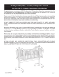
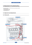
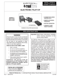
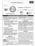
1
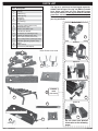
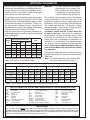
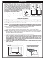
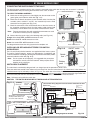
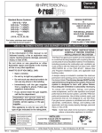
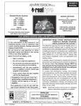
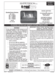
OWNER’S
MANUAL
Standard Burner Systems:
DESIGN CERTIFIED
G45-**(P)A
G45-**-01(M)(P)
G45-**-11(M)(P)
G45-**-15(M)(P)
G45-**-17(M)(P)
to
Vented Decorative Appliance
ANSI Z21.60-2012
CSA 2.26-2012
**Sizes:
(16/19, 18/20, 24, 30, 36)
FOR INSTALLATION IN
SOLID-FUEL BURNING
FIREPLACES*
For indoor stainless steel models;
add (-SS) to end of model #
G45 SERIES VENTED GAS LOG SETS (REGULATED)
IMPORTANT: READ THESE INSTRUCTIONS
CAREFULLY BEFORE STARTING
INSTALLATION OF THE LOG SET
WARNING
If the information in this manual is not
followed exactly, a fire or explosion may
result, causing property damage, personal
injury, or loss of life.
The Real-Fyre gas log set is to be installed only in a
solid-fuel burning fireplace with a working flue and
constructed of noncombustible material.The installation,
including provisions for combustion and ventilation air
must conform with the National Fuel Gas Code, ANSI
Z223.1/NFPA 54, or the CSA B149.1, Natural Gas
and Propane Installation Code, and applicable local
building codes.
A damper clamp is included to maintain the minimum
permanent vent opening and to prevent full closure of
the damper blade. The chimney damper MUST be
fully opened when burning the log set.The log set is
designed to burn with yellow flames; thus adequate
ventilation is absolutely necessary.
To comply with certification, listings, and building
code acceptances, and for safe operation and proper
performance of this log set, use ONLY Peterson
parts and accessories. Use of other controls, parts,
and accessories that are not designed for use with
Real-Fyre gas log sets is prohibited and will void all
warranties, certifications, listings, and building code
approvals, and may cause property damage, personal
injury, or loss of life.
*Note: Solid-fuels shall not be burned in a fireplace
where a decorative appliance is installed.
Do not store or use gasoline or other
flammable vapors and liquids in the vicinity
of this or any other appliance.
WHAT TO DO IF YOU SMELL GAS:
• Open a window.
• Do not try to light any appliance.
• Do not touch any electrical switch; do
not use any phone in the building.
• Immediately call the gas supplier
from a neighbor’s phone. Follow gas
supplier’s instructions.
• If you cannot reach the gas supplier,
call the fire department.
Installation and service must be
performed by a qualified professional
installer, service agency, or the gas
supplier.
This appliance is only for use with the
type of gas indicated on the rating plate.
INSTALLER:
Leave this manual with the appliance.
CONSUMER:
Retain this manual for future reference.
11-020
ROBERT H. PETERSON CO. • 14724 East Proctor Avenue • City of Industry, CA 91746
REV 5 - 1301080756
1
L-A2-208
manuel des
propriétaires
Systèmes standard de brûleur:
G45-**(P)A
G45-**-01(M)(P)
G45-**-11(M)(P)
G45-**-15(M)(P)
G45-**-17(M)(P)
CONCEPTION CERTIFIÉE
à
Vented Decorative Appliance
ANSI Z21.60-2012
CSA 2.26-2012
**Sizes:
(16/19, 18/20, 24, 30, 36)
POUR L’INSTALLATION EN
CHEMINÉES BRÛLANTES DE
COMBUSTIBLE SOLIDE*
Pour les modèles d'intérieur
d'acier inoxydable ; ajoutez (-SS)
à l'extrémité du modèle #
LA SÉRIE G45 A EXHALÉ LA NOTATION DE GAZ RÉGLÉE (RÉGLÉ)
IMPORTANT: L I S E Z C E S I N S T RU C T I O N S
SOIGNEUSEMENT AVANT DE
COMMENCER L'INSTALLATION DE
L'ENSEMBLE DE NOTATION.
L'ensemble de notation de gaz d'Real-Fyre doit être
installée seulement dans une cheminée brûlante de
combustible solide avec une conduite de cheminée
fonctionnante et être construit avec du matériel noncombustible. L'installation, y compris des dispositions
pour l'air de combustion et de ventilation doit se
conformer au code national de gaz de carburant, la
norme ANSI Z223.1/NFPA 54, ou le CSA B149.1, code
d'installation de gaz naturel et de propane, et codes du
bâtiment locaux applicables.
Une bride plus humide est incluse pour maintenir
l’ouverture permanente minimum de passage et pour
empêcher la pleine fermeture de la lame plus humide.
L’amortisseur de cheminée DOIT être entièrement ouvert
en brûlant la notation réglée. L’ensemble de notation
est conçu pour brûler avec les flammes jaunes; ainsi à
ventilation proportionnée est absolument nécessaire.
Pour se conformer à la certification, les listes, et
les acceptations de codes du bâtiment, et pour
l'exploitation sûre et l'exécution appropriée de cet
ensemble de notation, utilisent SEULEMENT des
pièces et des accessoires d'Peterson. L'utilisation
d'autres commandes, pièces, et accessoires qui ne
sont pas conçus pour l'usage avec des ensembles
de notation de gaz d'Real-Fyre est interdite et
videra toutes les garanties, certifications, listes, et
approbations de codes du bâtiment, et peut causer
des dégats matériels, le dommage corporel, ou des
pertes humaines.
*Note: des Plein-carburants ne seront pas brûlés
dans une cheminée où un appareil décoratif
est installé.
AVERTISSEMENT
Si l’information en ce manuel n’est pas
suivie exactement, une incendie ou une
explosion peut résulter, entraînant des dégats
matériels, des blessures, ou la perte de la vie.
Ne stockez pas ou n’employez pas l’essence
ou d’autres vapeurs et liquides inflammables à
proximité de ceci ou d’aucun autre appareil.
CE QUI À FAIRE SI VOUS SENTEZ LE GAZ:
• Ouvrez une fenêtre.
• N’essayez pas de n’allumer aucun appareil.
• Ne touchez aucun commutateur
électrique; n’utilisez aucun téléphone
dans le bâtiment.
• Appelez immédiatement le fournisseur
de gaz du téléphone du voisin. Suivez les
instructions du fournisseur de gaz.
• Si vous ne pouvez pas atteindre le
fo u r n i s s e u r d e g a z , a p p e l e z l e
département de feu.
L’installation et le service doivent être assurés par
un installateur qualifié et professionnel, l’agence
de service, ou le fournisseur de gaz.
Cet appareil sert seulement avec le type de gaz
indiqué de la plaque de contrôle.
INSTALLATEUR :
Laissez ce manuel avec l'appareil.
CONSOMMATEUR:
Maintenez ce manuel pour la future référence.
11-020
ROBERT H. PETERSON CO. 14724 East Proctor Ave., City of Industry, CA 91746 , USA
REV 5 - 1301080756
2
L-A2-208
TABLE OF CONTENTS
4
5
5
6
6
7
8
9
9
10
11
12
14
14
14
15
17
19
21
23
24
25
26
PARTS LIST
SAFETY CONTROL SYSTEM FOR MANUAL SERIES
SAFETY CONTROL SYSTEM FOR 17 SERIES
SAFETY CONTROL SYSTEM FOR 15 SERIES
SAFETY CONTROL SYSTEM FOR 01 SERIES
SAFETY CONTROL SYSTEM FOR 11 SERIES
IMPORTANT INFORMATION
INSTALLATION
INSTALLING THE BURNER
GRANULE, EMBER, AND GRATE PLACEMENT
01 VALVE MODELS ONLY
LOG PLACEMENT
OPTIONAL CHARRED SERIES INSTALLATION
GLOWING EMBERS PLACEMENT
LOG PLACEMENT
LIGHTING INSTRUCTIONS - MANUAL PILOT AND SERIES 17 VALVE
LIGHTING INSTRUCTIONS - SERIES 15 VALVE
LIGHTING INSTRUCTIONS - SERIES 01 VALVE
LIGHTING INSTRUCTIONS - SERIES 11 VALVE
PILOT BURNER ADJUSTMENT
TROUBLESHOOTING
FLAME DESCRIPTION
WARRANTY
REV 5 - 1301080756
3
L-A2-208
PARTS LIST
The log set is purchased and packaged separately.
Golden Oak Designer Plus log set (RDP-24) shown
here. Styles and sizes will vary depending upon
the log set ordered. If the log set ordered includes
placement instructions; follow those instructions.
When ordering replacement parts; be sure to indicate
your log set model.
Item Description
1.
2.
3.
4.
5.
6.
7.
8.
9.
10.
or
11.
12.
or
13.
14.
or
15.
16.
17.
Rear log
Front log
Middle left log
Middle right log
Top left log
Top right log
Top center log
Grate
Log locator (with screws & nuts)
Standard burner pan
Stainless steel burner pan
Flame diverter bracket
Fuel injector (for natural gas only)
Air mixer (for propane gas only)
Control valve system (see insets)
Select sand granules (natural gas only)
Vermiculite granules (propane only)
Embers
Damper clamp
Connector kit (with adapter)
Manual valve
13
Series 11
Note: Photos not to scale.
7
13
6
5
3
Series 15
4
9
1
14
13
2
Series 17
13
Control
valve
(see insets)
8
13
Series 01
17
10
(Standard burner pan shown)
11
15
16
REV 5 - 1301080756
12
13
For all valves, see detailed
information on the following
pages.
4
L-A2-208
SAFETY CONTROL SYSTEM FOR MANUAL SERIES
Pressure
tap
4
5
Item Description
2
1.
2.
3.
4.
or
5.
or
3
1
Control knob w/ extension
Manual SPK valve
heat shield kit
Pressure regulator, natural gas
Pressure regulator, propane gas
Pilot assembly, natural gas
Pilot assembly, propane gas
SAFETY CONTROL SYSTEM FOR 17 SERIES
2
4
3
1
Remote
connects here
5
Item Description
1.
2.
or
3.
4.
or
5.
6.
REV 5 - 1301080756
Valve
Pilot assembly, natural gas
Pilot assembly, propane gas
Heatshield kit
Pressure regulator, natural gas
Pressure regulator, propane gas
Control knob w/ extension
Remote kit (if equipped)
6
All replacement parts may be obtained from
the nearest Real-Fyre® dealer. For assistance in
locating a dealer, you may contact the address
listed on the front page.
5
L-A2-208
SAFETY CONTROL SYSTEM FOR 15 SERIES
1
2
3
6
4
Item Description
1.
2.
or
3.
or
4.
or
5.
6.
5
Heatshield kit
Pressure regulator, natural gas
Pressure regulator, propane gas
Pilot assembly (natural gas)
Pilot assembly (propane gas)
Valve, natural gas
Valve, propane gas
Remote kit (if equipped)
Decorative wood chunk
SAFETY CONTROL SYSTEM FOR 01 SERIES
2
Item Description
1.
or
2.
or
3.
4.
5
1
Pilot assembly (natural)
Pilot assembly (propane)
Valve assembly (natural)
Valve assembly (propane)
Heatshield
3
Switch box assembly
Remote kit (if equipped)
5
4
REV 5 - 1301080756
6
L-A2-208
SAFETY CONTROL SYSTEM FOR 11 SERIES
Item Description
1.
2
or
3
or
4.
4
Heatshield
Valve assembly (natural)
Valve assembly (propane)
Pilot assembly (natural)
Pilot assembly (propane)
Remote kit (if equipped)
3
1
2
REV 5 - 1301080756
7
L-A2-208
IMPORTANT INFORMATION
Important:
For safe operation and proper
performance and to comply with
CSA Certification, ONLY Robert
H. Peterson parts and accessories
must be used with this gas log set.
The minimum inlet gas supply pressure for purpose
of input adjustment is 5" for natural gas and 11" for
propane gas. Maximum inlet gas supply pressure for
this burner is 10.5" for natural and 13" for propane gas.
Gas supply pipe must be 1/2" minimum interior
diameter or larger. If the gas line is longer than 20',
a larger diameter line may be necessary.
A fireplace screen must be in place when the
system is burning. Provisions for adequate
combustion air must be maintained. Unless other
provisions for combustion air are provided, the
screen shall have an opening(s) for introduction of
combustion air. Combustion air is adequate when
all flames curl into the fireplace and away from the
screen. When a glass fireplace enclosure (door) is
used, leave the doors fully open when the system
is in operation.
The minimum firebox dimensions in which log set is
certified to be installed, is listed in the Technical Data
Table here.
Note: For remote ready units, the maximum BTU
thru put of some valves may vary.
Do not use this log set if any part has been
underwater. Immediately call a qualified professional
service technician to inspect the appliance and to
replace any part of the control system and any gas
control which has been underwater.
The gas log set must be isolated from the gas supply
piping system by closing its individual shut-off valve
during any pressure testing of the gas supply system
at test pressures equal to or less than 1/2 psig. The
gas log set and its individual shut-off valve must be
disconnected from the gas supply piping system when
testing at pressures in excess of 1/2 psig.
Keep the area of the gas log set clear and free from
combustible materials, gasoline, and other flammable
vapors and liquids.
Min. Fireplace Dimensions
Burner
size
Width
BTU
Depth Height
Front* Rear
NAT.
L.P.
16/19"
29"
23"
11"
18"
40k
30k
18/20"
30"
24"
14"
18'
70k
45k
24"
34"
28"
14"
18"
90k
65k
30"
40"
34"
15"
18"
95k
75k
36"
46"
40"
16"
18"
95k
75k
* This required width allows for centering of the log set.
Note:
Rear width is at corresponding depth.
Minimum Free Opening Area of Chimney Damper for Venting (sq. in.)
For Factory-Built Fireplaces
For Masonry-Built Fireplaces
Chimney
16/19"
18/20"
24"
30"
36"
16/19"
18/20"
24"
30"
36"
15' (min.)
25
44
57
60
60
29
48
61
64
64
20'
23
40
51
54
54
27
44
55
58
58
25'
22
38
49
51
51
-
-
-
-
-
30'
20
36
46
48
48
24
40
50
52
52
Note: The minimum chimney height from hearth to top of chimney is 15'.
THE FOLLOWING LOG STYLES ARE COMPATIBLE WITH THE G45 BURNER SYSTEM:
RDP:
FO:
FOS:
CR:
ACR:
RED:
S:
SDP:
RRSO:
WO:
Golden Oak Designer Plus
Forest Oak
Forest Split Oak
Cedar
Aged Cedar
Red Oak
Split Oak
Split Oak Designer Plus
Rugged Split Oak
Woodland Oak
BD:
HD:
W:
WCF:
CHD:
CHS:
CHRED:
CHCR:
CHACR:
CHRRSO:
Royal English Oak Designer
Heritage Oak Designer
White Birch
Western Campfyre
Charred Oak
Charred Split
Charred Red Oak
Charred Cedar
Charred Aged Cedar
Charred Rugged Split Oak
CHB:
CHF:
CHN:
NO:
R:
RRO:
PO:
B:
H:
CDR:
Charred Royal English Oak
Charred Forest Oak
Charred Northern Oak
Noble Oak
Golden Oak
Rugged Oak
Post Oak
Royal English Oak
Heritage Oak
Coastal Driftwood
IMPORTANT
For all valves, the air MUST be purged from the gas line before the pilot will light and burn properly. The time
needed to purge will depend on the length of the gas line to the unit and the amount of time since the unit or gas
line was last used. It may take several minutes before all the air is purged and the pilot will light and burn properly.
Follow the LIGHTING INSTRUCTIONS section in this manual.
REV 5 - 1301080756
8
L-A2-208
INSTALLATION
The damper clamp with hex bolt (Fig. 9-1) is provided as a means to
prevent full closure of the damper blade. The clamp is easily attached to
most damper blades with pliers or a wrench, and must be permanently
installed. The clamp is designed to prevent accidental closure of the damper
when installed as illustrated (Fig. 9-2 and Fig. 9-3). Should the clamp not
fit, or fail to provide the permanent vent opening listed in the table found
above, have a permanent stop installed, remove the
damper blade, or have the damper cut to provide Set screw
the minimum permanent opening required.
Note: These are minimum damper opening
specifications. The damper must be
completely opened when operating this
gas appliance to achieve the best ventilation
possible.
Damper clamp
Fig. 9-1
Open
Closed
Fig. 9-2
Fig. 9-3
INSTALLING THE BURNER
The Real-Fyre gas log set must be installed by a qualified professional service technician. Instructions
must be followed carefully to ensure proper performance and full benefit from the gas log set. Check to be
sure the log set is designed and labeled for the type of gas (natural or propane gas) supplied to the
fireplace. Fireplace floor must be level, clean, and smooth.
WARNING: Failure to position the parts in accordance with these diagrams or failure to use only parts
specifically approved with this appliance may result in property damage or personal injury.
REFER TO THE PARTS LIST WHEN FOLLOWING THESE INSTRUCTIONS.
1. MAKE SURE THE FIREPLACE GAS SUPPLY IS TURNED OFF.
2. Locate the gas-supply stub inside the fireplace and remove the cap, if attached (see Fig. 9-4).
CAUTION: When removing the cap, make sure the stub does not turn, loosening the connection inside the wall.
3. Attach the nut end of the flex connector (Item 16) to the adapter found on the valve or, if attached, on
the regulator behind the valve. Tighten securely.
4. Place the burner system into the fireplace so the open burner pan faces outward.
5. Locate the grate (Item 7) and attach the log locators (Item 8) to the 2 outer bars of the grate with screws
and nuts. The log locators should be loosely positioned toward the middle of the bars with screw slots
facing towards fireplace side walls (Fig. 9-5). Temporarily place the front log at the front of the grate, to
correctly determine the log locator position. Slide the log locators up against the rear of the front log.
Tighten the log locators in place. Remove t he front log.
6. Place the grate over the burner pan so the log locator brackets fit over the back edge of the burner pan
to lock it in position.
7. Center this assembly in the fireplace and place it as far back in the fireplace as possible. Remove the
grate for the gas connection and granule/ember placement.
Fig. 9-4
Fig. 9-5 Log locators on grate
Gas line
cap
(Brackets are to fit over
back edge of burner pan)
Gas supply
line stub
REV 5 - 1301080756
9
L-A2-208
INSTALLATION (cont.)
8. Be sure gas to the fireplace is off. Attach the large adapter end of the flex connector (Item 16) to the
gas-supply stub using a pipe compound resistant to all gases. Ensure adapter (and nut) are tightened
securely. Ensure the pan rests level on the fireplace floor after connection. Adjust the pan if necessary.
9. LEAK TEST: Turn on the fireplace gas supply, and test at all connections for leaks using the appropriate
soapy water solution. If bubbles appear, a leak is present. Turn off the gas and tighten at all connections.
Repeat until no leaks are present. If a leak persists, turn off the gas supply and contact the local gas
company or dealer. NEVER USE A FLAME TO CHECK FOR LEAKS.
Turn off the gas supply prior to proceeding.
10. Place the heatshield over the regulator and/or valve.
Important:
Heatshields must be in place during operation of the gas log set. Overheating of the valve
will cause shut down of the gas log set or other operating problems.
GRANULE, EMBER, AND GRATE PLACEMENT
GRANULE PLACEMENT
The granules supplied with the unit are specially selected for
use with either propane gas or natural gas. They maximize
flame distribution and reduce carbon buildup.
1. Fill the burner pan completely with the granules* (Item 13).
See Fig. 10-1. Avoid spilling the granules on the pilot
kit.
*Note: Use only select sand for natural gas burners and
vermiculite for propane gas burners.
2. Slope the granules at the same angle as the burner pan.
This is important to ensure quiet lighting and even flame
distribution.
Back wall
of fireplace
Place granules in
pan & slope to angle
of pan
Burner pan
Fig. 10-1 Granule placement
EMBER PLACEMENT
Sprinkle the glowing embers (Item 14) lightly and evenly over the entire surface of the granules. Break up
any clumps that may have developed during shipment. (For Charred series log sets, refer to OPTIONAL
CHARRED SERIES INSTALLATION section.)
Important: Do not add any additional embers to this log set. Any additional embers may cause
unsafe operation.
GRATE PLACEMENT
Replace the grate so that the bottom tabs on the log locator brackets fit over the back edge of the pan,
locking it in position.
REV 5 - 1301080756
10
L-A2-208
01 VALVE MODELS ONLY
CONNECTING THE IGNITION PACK TO THE VALVE
The 01valve comes complete with the wiring harness connected to the switch box. You may wish to ensure it is correctly
connected before finally connecting the three wires to the valve, as below.
Check Connections
TO CHECK THE WIRING ASSEMBLY:
"I" wire
B
A. Check that the wiring harness is fitted tightly into the connector on the
green ignitor pack inside the switch box (Fig. 11-1).
"S" wire
A
Wire harness
connector
B. Check that the female connectors on the two black wires from the pilot
assembly (wires marked "I" and "S") are inserted fully into the male
connectors on the ignitor pack (Fig. 11-2).
C. Check the connection of the red and black wires of the wire harness to
the respective counterpart wires from the battery holder (red-red and
black-black). The two brown wires should be connected to the switch.
Note:
Fig. 11-1
Ignitor pack
The two spare brown wires with coated male connectors are used
to connect a remote system (if equipped).
Fig. 11-2
D. Connect the wires to the valve in the following order (see Fig. 11-2):
D
Orange wire marked THTP - to THTP connector on valve
Black wire marked TP - to TP connector on valve
Green wire
marked THTP
Black wire marked TP
Orange wire marked THTP
Green wire marked TH - to TH connector on valve
The diagram below shows the wiring layout for the complete unit.
INSTALLING OR REPLACING BATTERIES FOR IGNITION
MODULE PACK
Two 1.5-volt (D-cell) alkaline batteries are supplied with the burner system.
To install or replace batteries, remove any old batteries (if applicable) and
install new batteries according to the diagram illustrated on the battery holder
mounted inside the switch box (Fig. 11-3).
Note:
ON/OFF switch
Fig. 11-3
Ignitor
pack
Switch
box
For the system to work properly, it is suggested that you replace
the batteries annually with fresh batteries. Always replace all the
batteries at the same time.
Battery
pack
SWITCH BOX PLACEMENT
The switch box is aesthetically designed and is an integral part of the operation of the 01 valve.
Place the switch box outside of the firebox and a minimum of 6" from the burner/flame. If the switch box is in the firebox, the
switch box must only be oriented as shown in Fig. 11-4. The switch box must not be placed in the rear of the fireplace, or in
any other manner than shown in Fig. 11-4. Set the box on its side and face the bottom of the box toward the right firebox wall.
Be sure that the pilot and valve wire bundles remain clear of the burner, valve, and heat shield at all times.
Note: Coil excess wire within the switch box.
CAUTION: THE SWITCH BOX MAY BE HOT DURING AND AFTER OPERATION.
Fig. 11-4
(FIREBOX)
Burner pan
Pilot wire
bundle
Consult this wiring diagram to ensure correct connection of wires.
Switch box
Valve magnet wire
(black)
(do not remove)
Wire harness
Orange (THTP)
Valve and heat shield
Wire bundles go around the valve
and away from the burner. Coil
excess wire under switch box.
6"
min
Rear of control panel
Remote valve
Valve wire
bundle
2x D cells
Switch box
IF SWITCH BOX IS INSIDE FIREBOX; ORIENT ONLY AS SHOWN
BELOW:
REV 5 - 1301080756
Green (TH)
Remote
receiver
(optional)
Brown 2
wires
wires to
(inside
switch
(inside of
box)
Ignitor pack
Switch
11
S
S
I
BOX ON ITS SIDE
Black (TP)
(Red) to
battery holder
switch box)
(FIREBOX)
(Black) to
Battery
holder
To pilot assembly
I
probes
Sensor
Ignitor
Wiring diagram for 01 Valve
Fig. 11-5
L-A2-208
LOG PLACEMENT
CAUTION: Burn hazard. Logs will remain hot for some time after use. You must maintain the
log layout as shown to ensure proper operation of your log set. If you need to
reposition any log to maintain the proper layout, use heat-resistant gloves or allow
logs adequate time to cool before handling.
Styles and sizes will vary depending upon the log set ordered. If the log set ordered includes
placement instructions; follow those instructions.
16/19" GAS LOG SETS
If you have a 16/19" log set, follow
the steps below.
Fig. 12-1
Step 1.
Step 1. Place the front and rear bottom logs on the
grate (Fig. 12-1). The face with the bark
effect should face out into the room. The
longest log is placed in front. The log locators
ensure that adequate space between the logs
is maintained for a cleaner burn.
Fig. 12-2
Step 2.
Right middle log
Left middle
log
Step 2. Place the left and right middle logs on the
bottom logs, as illustrated in Fig. 12-2.
Step 3. Place the front top log with one end resting
on top of the front end of the left middle log.
The other end will rest on the front bottom
log. Place rear top log with one end resting
on top of the back end of right middle log.
The other end will rest on the rear bottom
log (Fig. 12-3).
Fig. 12-3
Step 3.
Rear top log
Front top
log
18"-36" ALTERNATIVE LOG PLACEMENT PATTERNS SUMMARY
The three illustrations below show the three log placement patterns available for Real-Fyre gas log sets.
The mirror image of each of the illustrations is also approved.
Option 1
REV 5 - 1301080756
Option 2
12
Option 3
L-A2-208
LOG PLACEMENT (Continued)
Note: For Charred Series, see instructions on the next page.
Proper log placement is important to ensure proper performance of the gas log set. Follow the log placement
instructions exactly. Three optional log placement patterns, an exclusive feature of Real-Fyre® gas logs, are
explained below.
Fig. 13-1 All options - Step 1
(For 16" log sets, see the previous page.)
18"-60" GAS LOG SETS
1
ALL OPTIONS
Step 1. Place the rear bottom log (log #1) on the back of the grate
(Fig. 13-1), and slide it forward against the log locators. Place
the front log (log # 2) on the front of the grate and slide it back
2
against the log locators. The log locators ensure that adequate
space between the logs is maintained for a cleaner burn.
24" Golden Oak (RDP) log set shown.
OPTION 1
Step 2. Place the two middle logs (logs #3 & #4) on the bottom logs (logs #1 & #2). The knotholes of the
middle logs are placed over the space between the front and rear bottom logs (Fig. 13-2).
Step 3. Top logs (logs #5 & #6) are placed with one end resting near the knothole of the middle logs and
the other resting on top of the front bottom log (Fig. 13-3).
Option 1 - Step 3.
Option 1 - Step 2.
3
4
5
6
Fig. 13-3
Fig. 13-2
OPTION 2
Step 2. Place the middle logs as instructed under option 1 (Fig. 13-2).
Step 3. Top log #5 is placed with one end near the knothole of the other middle log and the other end
resting on the bottom rear log. Top log #6 is placed with one end near a middle log knothole and
the other end resting on the bottom front log, as shown in Fig. 13-4.
OPTION 3
Step 2. Place the middle logs (logs #3 & #4) so they are parallel, resting on the bottom logs with the
knotholes over the space between the bottom logs.
Step 3. Place top logs (logs #5 & #6) parallel to each other, across the middle logs, as shown in Fig. 13-5.
Option 3 - Step 2 & 3.
Option 2 - Step 3.
5
3
5
4
6
6
Fig. 13-4
Fig. 13-5
OPTIONAL BONUS LOG PLACEMENT FOR 18"-60" LOG SETS
If the log set contains an optional bonus log (included with
Emberwood Deluxe, Emberwood Deluxe Designer, Golden
Oak Designer Plus, and Split Oak Designer Plus log sets), it
should be placed directly above the front or rear bottom logs
(logs #1 and #2), so it does not extend into the space between
the front and rear logs (Fig. 13-6).
REV 5 - 1301080756
13
7
Fig. 13-6
Bonus log
above rear
log
L-A2-208
OPTIONAL CHARRED SERIES INSTALLATION
GLOWING EMBERS PLACEMENT
Attach the ember bed (Part No. CHD-01) to the burner
by slipping it onto the back edge (center left to right) with
the perforated section facing towards the back fireplace
wall (Fig. 14-1).
Cover the surface of the ember bed with the glowing
embers supplied with the Charred series log set, as shown
in Fig. 14-2.
Note:
For best glowing performance, they should be
applied evenly and pulled slightly apart so the
fibers are somewhat loose.
Important:
Fig. 14-1
Ember bed
Part No.
CHD-01
Fig. 14-2
Glowing embers
Part No.
EM-4
It is not necessary to pile the entire bag
of the glowing embers. More glowing
LOG PLACEMENT
Step 1.
Step 2.
Note:
Step 3.
Log styles and sizes will vary depending upon the Charred series log set ordered.
CHARRED SPLIT OAK DESIGNER PLUS (SDP) layout shown.
Note: The charred sections should be over the
Place the long bottom rear log (log #2) on the
opening between the front and rear logs
back of the grates with the flat, featureless
(Fig. 14-4).
side facing the rear of the fireplace. Slide it
forward to touch the log locator.
The two sections of the front log (logs #1A & Step 4. Place the small top charred logs (logs #5 &
#6) so they rest over the charred sections
1B) are placed on the front of the grate with
of the front bottom log sections (logs # 1A
the charred sections facing each other and
& 1B) and on the two curved logs (logs #3
approximately 1" apart at the top (Fig. 14-3).
& #4) (Fig. 14-5).
Slide them back against the log locators.
The log locators ensure that adequate
Step 5. Place the curved top charred log (log #7)
space between front and rear logs are
to rest on the two top logs at rear, but not
maintained for a cleaner burn.
encroaching into the space between rear
Place the two curved logs (logs #3 & #4) so
and front logs (Fig. 14-6).
that one end rests on each front log section
Note: The additional top log (log #7) is not
(logs #1A & 1B) and the other end rests on
available with 18" log sets.
the rear log (log #2).
Fig. 14-4
Fig. 14-3
LOG #1A
#4
LO
G
G
LO
#3
LOG #2
LOG #1B
MAINTAIN A SPACE IN THE CENTER OF
THE LOGS AT ALL TIMES
Fig. 14-5
Fig. 14-6
LOG #7
LO
G
REV 5 - 1301080756
#5
G
#6
LO
14
L-A2-208
LIGHTING INSTRUCTIONS - MANUAL PILOT AND SERIES 17 VALVE
FOR YOUR SAFETY, READ BEFORE LIGHTING
WARNING
If you do not follow these instructions exactly, a fire or explosion may result, causing property
damage, personal injury, or loss of life.
Do not use this appliance if any part has been underwater. Immediately call for a qualified professional service technician to
inspect the appliance and to replace any part of the control system and any gas control that has been underwater.
The Real-Fyre® burner system has a pilot that can be lit by hand using a match or lighter. When lighting the pilot, follow these
instructions exactly.
BEFORE LIGHTING, smell all around the burner area for gas. Be sure to smell next to the floor, as some gas is heavier than
air and will settle on the floor. IF YOU SMELL GAS, FOLLOW THE INSTRUCTIONS ON P. 1.
Use only your hand to push in or turn the gas control knob. Never use tools. If the knob will not push in or turn by hand, don't try
to repair it. Call a qualified professional service technician. Excessive force or attempted repair may result in fire or explosion.
LIGHTING THE PILOT
IGNITING THE MAIN BURNER
1. Push in the gas control knob slightly and turn
to OFF (Fig. 15-1). Refer to
clockwise
the PARTS LIST for the location of the burner
control valve knob.
1. Make sure the pilot is burning.
2. Turn the gas control knob counterclockwise
to ON (Fig. 15-1) to ignite the burner. The burner
will ignite.
Note: The burner control knob cannot be turned
from PILOT to OFF unless the knob is
pushed in slightly. Do not force.
Note: Periodically check the pilot flame for the
proper flame pattern (Fig. 15-1).
MAKE SURE THE THERMOCOUPLE AND PILOT
ASSEMBLY ARE IN CORRECT ALIGNMENT WITH
EACH OTHER (Fig. 15-1).
Wait five minutes to clear out any gas. If you then
smell gas, STOP! Notify your gas supplier or the
fire department immediately. If you don’t smell gas,
go on to step 2.
TURNING OFF THE MAIN BURNER
2. Turn the burner control knob counter-clockwise
to PILOT (Fig. 15-1). Push the control
knob firmly and fully in and hold. Hold a long
fireplace match or lighter near the thermocouple
to light the pilot. Continue to hold the control
knob in for approximately 30 seconds after the
pilot is lit, then release the knob. The pilot will
remain lit.
If the pilot will not stay lit after several tries,
turn the gas control knob to OFF and call your
service technician or gas supplier.
The series 17 valve is capable of remote operation. If this
unit was shipped with a remote, or if a remote system
was installed later, read and follow the separate remote
instructions to operate the burner remotely.
OFF
(Manual valve shown)
Thermocouple
OFF
ON
1. Lighting -Turn the burner control knob
to OFF
and wait 5 minutes before
lighting.
PILOT
ON
PILOT
Pilot
PILOT
ON
ON
PILOT
•
1. If complete shutdown is desired, from the PILOT
position, push in the control knob slightly and
to the OFF position. Do not
turn clockwise
force the knob. This will require the pilot to be
relit before using the burner again.
OFF
If the pilot will not light, repeat steps 1 and 2.
EXTINGUISHING THE PILOT
OFF
•
1. From the ON position, turn the control knob
clockwise
to the PILOT position. The burner
will extinguish, and the pilot will remain lit.
3. Tur n the knob
1. Tu r n t h e k n o b 2. Turn knob
counterclockwise
counterclockwise
clockwise to OFF
to ON to light the
to PILOT position. With
only when
burner.
match ready, press
complete shutdown
knob in and hold for 60
is desired or prior to
seconds while lighting
lighting the pilot.
pilot.
Pilot Assembly
Fig. 15-1
15
INSTRUCTIONS D’ÉCLAIRAGE - PILOTE ET VALVE MANUELS DE LA SÉRIE 17
POUR VOTRE SÛRETÉ, LISEZ AVANT DE S’ALLUMER
AVERTISSEMENT: Si vous ne suivez pas ces instructions exactement, une incendie ou une
explosion peut résulter entraînant des dégats matériels, des blessures ou la perte de la vie.
N’employez pas cet appareil si n’importe quelle partie a été sous-marine. Réclamez immédiatement un technicien
de service professionnel qualifié et pour inspecter l’appareil et pour remplacer n’importe quelle partie du système de
commande et de n’importe quelle commande de gaz qui a été sous l’eau.
Le Vrai-Fyre système de brûleur a un pilote qui peut être allumé à la main en utilisant une allumette ou un allumeur. En allumant le pilote,
suivez ces instructions exactement.
AVANT DE S’ALLUMER, sentez tous autour du secteur de brûleur pour le gaz. Soyez sûr de sentir à côté du plancher car un certain gaz
est plus lourd que l’air et arrangerez sur le plancher. SI VOUS SENTEZ LE GAZ, SUIVEZ LES INSTRUCTIONS À LA P. 1.
Utilisez seulement votre main pour enfoncer ou pour tourner le bouton de commande de gaz. N’utilisez jamais les outils. Si le bouton
n’enfoncera pas ou ne tournera pas à la main, n’essayez pas de le réparer. Appelez un technicien de service professionnel qualifié et. La
force ou la réparation essayée peut avoir comme conséquence l’incendie ou l’explosion.
ALLUMER LE PILOTE
ALLUMAGE DU BRÛLEUR PRINCIPAL
1. Si le bouton de soupape de commande de brûleur n’est
pas dans la position de OFF, enfoncez la poignée de
commande de gaz légèrement et tournez-vous dans
le sens des aiguilles d’une montre
vers OFF (fig.
16-1).
1. Assurez-vous que le pilote brûle.
2. Tournez la poignée de commande de gaz dans le sens
contraire des aiguilles d’une montre
à ON (fig. 161) pour mettre à feu le brûleur. Le brûleur mettra à feu.
Note: Examinez périodiquement la flamme pilote pour
Le bouton de commande de brûleur ne peut pas
assurer le modèle approprié de flamme (Fig. 16-1).
être tourné du PILOT au OFF à moins que la
poignée soit enfoncée légèrement. Ne forcez pas. ASSUREZ-VOUS QUE LE THERMOCOUPLE ET
Attendez cinq minutes pour dégager dehors n’importe quel L’ASSEMBLÉE PILOTE SONT EN ALIGNEMENT
gaz. Si vous sentez alors le gaz, ARRÊTEZ ! Informez votre CORRECT AVEC L’UN L’AUTRE (FIG. 16-1).
fournisseur de gaz ou le département de feu immédiatement.
ROTATION OUTRE DU BRÛLEUR PRINCIPAL
Si vous ne sentez pas le gaz, passez dessus à l’étape 2.
Note:
Si le pilote ne s’allumera pas, répétez les étapes 1. et 2.
•
Si le pilote ne restera pas s’allumait après que plusieurs
essais, tournent la poignée de commande de gaz à
OFF et appellent votre fournisseur de technicien ou
de gaz de service.
S’ÉTEINDRE LE PILOTE
1. Si complet l’arrêt est désiré, de la position PILOT,
de l’enfoncer le bouton de commande légèrement
et du tour dans le sens des aiguilles d’une montre
à la position de repos. Ne forcez pas le bouton.
NE FORCEZ PAS LE BOUTON. Ceci exigera du
pilote d’être re-s’est allumé avant d’utiliser le brûleur
encore.
Le SPK-17 est capable de l’éclairage à distance.
Si votre unité est équipée d’un extérieur, lisez
et suivez les instructions à distance séparées
d’actionner le brûleur à distance.
OFF
(valve manuelle montrée)
Thermocouple
OFF
ON
1. S’ALLUMER - tournez le bouton
de commande de brûleur à OFF
et attendez 5 minutes avant de
s’allumer.
Fig. 16-1
PILOT
ON
PILOT
Pilot
PILOT
ON
ON
PILOT
•
1. De la position de ON, tournez le bouton de commande
dans le sens des aiguilles d’une montre
à la position
PILOT. Le brûleur s’éteindra et le pilote restera s’est
allumé.
OFF
le sens contraire des aiguilles d’une montre
au
PILOT (fig. 16-1). Poussez la poignée de commande
toute la manière dedans et tenez-la. Tenez une longue
allumette de cheminée ou un proche plus léger le
thermocouple pour allumer le pilote. Continuez à tenir
le bouton de commande pour approximativement 30
secondes après que le pilote est allumé pour permettre
au thermocouple de détecter la flamme pilote, puis
libérez le bouton. Le pilote restera s’est allumé.
OFF
2. Tournez le bouton de commande de brûleur dans
1. Tournez le cadran dans 2. Tournez le cadran dans 3.
le sens des aiguilles
le sens contraire des
à
d’une montre
aiguilles d’une montre
OFF seulement quand
à la position PILOT.
l’arrêt complet est
Avec le bouton prêt de
nécessaire.
pression d’allumette
dedans et la prise
pendant 60 secondes
tout en allumant le pilote.
16
Tournez le bouton
contre- dans le
sens des aiguilles
d’une montre à ON
au brûleur léger.
LIGHTING INSTRUCTIONS - SERIES 15 VALVE
FOR YOUR SAFETY, READ BEFORE LIGHTING
WARNING
If you do not follow these instructions exactly, a fire or explosion may result, causing property
damage, personal injury, or loss of life.
Do not use this appliance if any part has been underwater. Immediately call for a qualified professional service technician
to inspect the appliance and to replace any part of the control system and any gas control that has been underwater.
The Real-Fyre® burner system has a pilot. When starting the pilot, follow these instructions exactly.
BEFORE LIGHTING, smell all around the gas burner system area for gas. Be sure to smell next to the floor, as some gas
is heavier than air and will settle on the floor. IF YOU SMELL GAS, FOLLOW THE INSTRUCTIONS ON P. 1.
Use only your hand to push in or turn the gas control knob. Never use tools. If the knob will not push in or turn by hand, don't
try to repair it. Call a qualified professional service technician. Force or attempted repair may result in fire or explosion.
(Fig. 17-4) to ignite the burner at maximum BTUs.
After the main burner ignites, adjust the flame height
as indicated below.
LIGHTING THE PILOT
1. Turn the ignitor control knob (Fig. 17-1) on the burner
control valve assembly to the side of the burner pan
counterclockwise
so that the narrowing part of the
knob moves from the OFF position, slightly toward IGN,
until reaching the stop.
ADJUSTING THE FLAME HEIGHT
2. Press the ignitor control knob in and hold in for five (5)
seconds (only pilot gas will flow).
1. To adjust the flame, turn the flame-height control knob
(Fig. 17-3) counterclockwise
to increase the flame
height, or clockwise
to decrease the flame height,
until the flames have the desired characteristics.
3. Continue pressing in while turning the ignitor control knob
further counterclockwise
toward the PILOT position
until you hear a click. The click is an indication that the
piezo ignitor has been activated.
2. When you are finished enjoying your fire, turn the flameheight control knob to OFF. The pilot will remain lit. The
burner system can be relit by rotating the flame-height
control knob toward ON.
Note: If the spark from the piezo ignitor does not
light the pilot, repeat steps 2 & 3 until the pilot
lights.
SHUTTING OFF THE PILOT
If you do not plan on using your burner system for an
extended period, you may elect to extinguish the pilot. To do
4. Continue to hold the ignitor control knob in the PILOT this, rotate the flame-height control knob to the OFF position
position for 60 seconds after the pilot has been lit to allow and then rotate the ignitor control knob to the OFF position
(Fig. 17-1).
the thermocouple to detect the pilot flame.
Important: When shutting the burner system down
Note: The pilot flame should always be present when
completely, turn the control/ignition knob to
the burner system is in operation, and should just
the OFF position (Fig. 17-1). If you desire to
envelop the tip of the thermocouple.
turn the unit back on, wait a minimum of one
IGNITING THE MAIN BURNER
(1) minute before starting the relight procedure
(LIGHTING THE PILOT). This allows the safety
1. When the pilot flame is stable, release the ignitor control
valve to reset in preparation for relighting.
knob and turn counterclockwise
to the ON position
to enable the main burner.
If this unit was shipped with a remote, or if a remote
2. Tur n the flame-height control knob (Fig. 17-3) system was installed later, read and follow the separate
counterclockwise
to the fully ON position remote instructions to operate the burner remotely.
OFF
IGNITION
PILOT
ON
Control/
ignition
knob
Flame-height
control knob
Gas valve operating positions
Fig. 17-1
Fig. 17-3
Thermocouple
Flame-height control knob
Fig. 17-2
OFF
17
Fig. 17-4
ON
INSTRUCTIONS D’ÉCLAIRAGE - VALVE DE LA SÉRIE 15
POUR VOTRE SÛRETÉ, LISEZ AVANT DE S’ALLUMER
AVERTISSEMENT : Si vous ne suivez pas ces instructions exactement, une incendie ou une
explosion peut résulter entraînant des dégats matériels, des blessures ou la perte de la vie.
N’employez pas cet appareil si n’importe quelle partie a été sous-marine. Réclamez immédiatement un technicien
de service professionnel qualifié et pour inspecter l’appareil et pour remplacer n’importe quelle partie du système de
commande et de n’importe quelle commande de gaz qui a été sous l’eau.
Le Vrai-Fyre® système de brûleur a un pilote qui peut être allumé à la main en utilisant une allumette ou un allumeur. En allumant le pilote,
suivez ces instructions exactement.
AVANT DE S’ALLUMER, sentez tous autour du secteur de brûleur pour le gaz. Soyez sûr de sentir à côté du plancher car un certain gaz
est plus lourd que l’air et arrangerez sur le plancher. SI VOUS SENTEZ LE GAZ, SUIVEZ LES INSTRUCTIONS À LA P. 1.
Utilisez seulement votre main pour enfoncer ou pour tourner le bouton de commande de gaz. N’utilisez jamais les outils. Si le bouton
n’enfoncera pas ou ne tournera pas à la main, n’essayez pas de le réparer. Appelez un technicien de service professionnel qualifié et. La
force ou la réparation essayée peut avoir comme conséquence l’incendie ou l’explosion.
Après que le brûleur principal mette à feu, ajustez la taille de
flamme comme indiqué ci-dessous.
ALLUMER LE PILOTE
1. Tournez le bouton de commande d’Ignitor (Fig. 18-1) de la
soupape de commande de brûleur au côté de la casserole de
de
brûleur dans le sens contraire des aiguilles d’une montre
sorte que la partie de rétrécissement du bouton se déplace de la
position de OFF, légèrement vers IGN jusqu’à atteindre l’arrêt.
AJUSTEMENT DE LA TAILLE DE FLAMMET
1. Pour ajuster la flamme, tournez le bouton de commande de taille
de flamme (Fig. 18-3) dans le sens contraire des aiguilles
à la taille de flamme d’augmentation et
d’une montre
à la taille de
dans le sens des aiguilles d’une montre
flamme de diminution jusqu’à ce que les flammes aient les
caractéristiques désirées.
2. Serrez le bouton de commande d’ignitor dedans et tenez dedans
pendant 5 secondes (seulement le gaz pilote coulera).
3. Continuez d’enfoncer tout en tournant le dans le sens contraire
supplémentaire de bouton de
des aiguilles d’une montre
commande d’ignitor, vers la position PILOT, jusqu’à ce que
vous entendiez un clic. Le clic est une indication que l’ignitor
de pizio a été activé.
Note:
2. Quand vous êtes fini appréciant votre feu, tournez le bouton
de commande de taille de flamme à OFF. Le pilote restera
s’est allumé. Le système de brûleur peut être relit en tournant
le bouton de commande de taille de flamme vers ON.
COUPER LE PILOTE
Si l’étincelle de l’ignitor de pizio n’allume pas le pilote,
répétez les étapes 2 et 3 jusqu’au pilote lights.
Si vous ne projetez pas sur employer votre système de brûleur
4. Continuez à tenir le bouton de commande d’ignitor en position pendant une période prolongée vous pouvez choisir de vous éteindre
PILOT pour 60 secondes après que le pilote a été allumé pour le pilote. Pour faire ceci, tournez le bouton de commande de taille
de flamme jusqu à la position de OFF et puis tournez le bouton de
permettre au thermocouple de détecter la flamme pilote.
commande d’ignitor jusqu à la position de OFF (Fig. 18-1).
Note: La flamme pilote devrait toujours être présent quand
le système de brûleur est en fonction, et devrait juste
Important: E n fe r m a n t l e s y s t è m e d e b r û l e u r
envelopper le bout du thermocouple.
complètement, tournez le bouton de control/
ignition à la position de repos (Fig. 18-1).
Si vous désirez tourner l’unité en arrière
dessus, attendez une minute au minimum
avant de commencer le procédé de rallumer
(ALLUMANT LE PILOTE). Ceci permet à la
soupape de sûreté de remettre à zéro en
vue de rallumer.
ALLUMAGE DU BRÛLEUR PRINCIPAL
1. Quand la flamme pilote est stable, libérez le bouton de
commande d’ignitor et tournez-vous dans le sens contraire
vers la position de ON pour
des aiguilles d’une montre
permettre le brûleur principal.
2. Tournez le bouton de commande de taille de flamme (Fig.
18-3) entièrement dans le sens contraire des aiguilles d’une Si cette unité était embarquée avec un extérieur, ou si un système
pleinement la position de fonctionnement (Fig. à distance était installé plus tard, lisez et suivez les instructions
montre
18-4) pour mettre à feu le brûleur chez BTUs maximum. à distance séparées d’actionner le brûleur à distance.
OFF
IGNITION
PILOT
ON
POSITIONS D’OPÉRATION DE CLAPET À GAZ
Fig. 18-1
BOUTON DE
COMMANDE/
D’ALLUMAGE
BOUTON DE
COMMANDE
DE TAILLE DE
FLAMME
Fig. 18-3
BOUTON DE COMMANDE DE
TAILLE DE
FLAMME
Thermocouple
Fig. 18-2
OFF
18
Fig. 18-4
ON
LIGHTING INSTRUCTIONS - SERIES 01 VALVE
FOR YOUR SAFETY, READ BEFORE LIGHTING
WARNING: If you do not follow these instructions exactly, a fire or explosion may
result, causing property damage, personal injury, or loss of life.
BEFORE LIGHTING, smell all around the gas burner area for gas. Be sure to smell next to the floor,
because some gas is heavier than air and will settle on the floor. IF YOU SMELL GAS, FOLLOW THE
INSTRUCTIONS ON P. 1.
1. STOP! Read the safety information above.
2. Turn off any electrical appliance used with the
burner system.
3. Verify the switch (marked I = IGNITE; O = OFF)
located on the front of the switch box is set to
"O" (OFF). Do not force.
4. Wait five (5) minutes to clear out any gas. If
you then smell gas, STOP! Follow the safety
information above. If you don't smell gas, go to
the next step.
Fig. 19-1
5. Depress the "I" (IGNITE) switch on the front of
the switch box. This transmits a rapid series of
sparks at the pilot head. These sparks cease
when the pilot flame is lit and stable. The pilot is
located at the rear right corner of the burner.
After a short time, the pilot will light the main
burner.
CAUTION: IF THE GAS SET DOES NOT
IGNITE WITHIN 20 SECONDS,
STOP, PRESS "O" (OFF), WAIT
FIVE (5) MINUTES, THEN REPEAT
STEPS 3-6.
1. LIGHTING - Verify the switch (marked I = IGNITE; O =
OFF) located on front of the switch box is set to O. Wait
five (5) minutes for the gas to clear out.
• The pilot should remain lit. If it goes out, repeat
steps 3 through 6.
• If the pilot will not stay lit after several tries, turn the
switch box to "O" (OFF) (Fig. 19-1) and call your
service technician or gas supplier.
1.
Press O (OFF) when
complete shutdown
is desired.
2.
Press I (IGNITE)
After a series of rapid
sparks, the pilot will
light. When the pilot is
stable, the main burner
will ignite.
6. To turn the set OFF, press the "O" (OFF) switch
on the front of the switch box. The gas flow will
cease, and all flames will go out.
If this unit was shipped with a remote, or if a
remote system was installed later, read and follow
the separate remote instructions to operate the
burner remotely.
SHUT-OFF INSTRUCTIONS - SERIES 01 VALVE
1. Put the switch in the OFF position. The burner will extinguish, and the pilot will go out.
19
INSTRUCTIONS D’ÉCLAIRAGE - SOUPAPE DE COMMANDE DE LA SÉRIE 01
POUR VOTRE SÛRETÉ, LISEZ AVANT DE S’ALLUMER
AVERTISSEMENT
Si vous ne suivez pas ces instructions exactement, une incendie ou une explosion peut résulter,
entraînant des dégats matériels, des blessures, ou la perte de la vie.
AVANT DE S’ALLUMER, sentez tous autour du secteur de brûleur à gaz pour le gaz. Soyez sûr de sentir à côté
du plancher parce qu’un certain gaz est plus lourd que l’air et arrangerez sur le plancher. SI VOUS SENTEZ LE
GAZ, SUIVEZ LES INSTRUCTIONS À LA PAGE 1.
1. ARRÊT! Lisez l’information de sûreté cidessus.
2. Arrêtez n’importe quel appareil électrique si utilisé
avec le système de brûleur.
3. Vérifiez le commutateur (marqué I = mettent à
feu ; O = au loin) situé sur l'avant de la boîte de
commutateur est placé au "O" ; (AU LOIN). Ne
forcez pas.
Fig. 20-1
4. Attendez cinq (5) minutes pour dégager dehors
n’importe quel gaz. Si vous sentez alors le gaz,
ARRÊTEZ ! Suivez l’information de sûreté cidessus. Si vous ne sentez pas le gaz, passez à
la prochaine étape.
5. Diminuez le "I" ; (METTEZ À FEU) branchez
l'avant de la boîte de commutateur. Ceci
transmet une série rapide d'étincelles à la tête
pilote. Ces étincelles cessent quand la flamme
pilote est allumée et écurie. Le pilote est situé
au bon coin arrière du brûleur. Après une brève
durée, le pilote allumera le brûleur principal.
ATTENTION: S I L’ E N S E M B L E D E G A Z N E
M E T PA S À F E U D A N S 2 0
SECONDES, ARRÊTEZ, TOURNEZ
L E C O M M U TAT E U R À “ O F F ” ,
ATTENDENT 5 MINUTES RÉPÈTENT
ALORS DES ÉTAPES 3-6.
1. ALLUMAGE - vérifiez le commutateur (marqué I =
mettent à feu ; O = au loin) situé sur l'avant de la boîte
de commutateur est placé aux minutes de l'attente cinq
d'O. (5) pour que le gaz se dégage
g dehors.
•
Le pilote devrait rester s’est allumé. S’il
sort, répétez l’étape 3 à 6.
•
Si le pilote ne restera pas allumé après
que plusieurs essais, tournent la boîte de
commutateur au "O" ; (AU LOIN) (fig. 20-1)
et appelez votre fournisseur de technicien
ou de gaz de service.
6. Pour arrêter l'ensemble, pressez le "O" ;
(AU LOIN) branchez l'avant de la boîte de
commutateur. L'écoulement de gaz cessera, et
toutes les flammes sortiront.
1.
Serrez “O” (= “off”)
quand l’arrêt complet
est désiré.
2.
Si cette unité était embarquée avec un extérieur,
ou si un système à distance était installé plus
tard, lisez et suivez les instructions à distance
séparées d’actionner le brûleur à distance.
Pression “I” (= “mettez à feu”) après
qu’une série d’étincelles rapides
que le pilote s’allumera. Quand le
pilote est stable, le brûleur principal
mettra à feu.
OUR ARRÊTER LE BRÛLEUR
1. Mettez le commutateur dans la position de repos. Le brûleur s’éteindra et le pilote sortira.
20
LIGHTING INSTRUCTIONS - SERIES 11 VALVE
FOR YOUR SAFETY, READ BEFORE LIGHTING
WARNING
If you do not follow these instructions exactly, a fire or explosion may result, causing property
damage, personal injury, or loss of life.
Do not use this appliance if any part has been underwater. Immediately call for a qualified professional service technician
to inspect the appliance and to replace any part of the control system and any gas control that has been underwater.
The Real-Fyre® burner system has a pilot that can be lit by hand using a match or lighter. When lighting the pilot, follow
these instructions exactly.
BEFORE LIGHTING, smell all around the burner area for gas. Be sure to smell next to the floor, as some gas is heavier than
air and will settle on the floor. IF YOU SMELL GAS, FOLLOW THE INSTRUCTIONS ON P. 1.
Use only your hand to push in or turn the gas control knob. Never use tools. If the knob will not push in or turn by hand, don't
try to repair it. Call a qualified professional service technician. Force or attempted repair may result in fire or explosion.
LIGHTING THE PILOT
ADJUSTING THE PILOT
To read the safety valve control knob (Fig. 21-1),
read the marking nearest the teardrop-shaped metal
pointer.
1. If the safety valve control knob is in the PILOT
position, push in slightly on the knob and rotate it
to the OFF position.
clockwise
2. Release knob and wait five (5) minutes.
3. Turn safety valve knob counterclockwise
to the
PILOT position. (Only the pilot gas will flow when
the knob is pushed in.)
4. Place a long match or a butane lighter at the pilot
burner, and at the same time, push the safety valve
knob fully in. The pilot will light.
5. Hold the safety valve knob in for approximately 60
seconds before releasing.
6. If the pilot does not stay lit, turn the safety valve
to the full OFF position. Wait five
knob clockwise
(5) minutes, then repeat steps 3 through 5.
a. The pilot flame should encircle the generator tip,
and is preset at the factory (Fig. 21-2).
b. If adjustment is necessary (Fig.21-1), turn the gas
to increase
adjustment screw counterclockwise
to decrease the
the pilot flame, or clockwise
pilot flame.
MAINTENANCE
Your pan burner is equipped with a safety pilot that will
shut off the gas supply in the event that the pilot is not
functioning properly. Make sure the pilot is adjusted
properly and that the generator spade clips are tightly
connected to the terminal screws on the valve. If the
pilot will not stay lit, call your local gas utility or gas
supplier.
A periodic check of the following should be performed
at least annually by a qualified professional service
representative:
1. Valves and toggle switch control for proper
operation.
IGNITING THE MAIN BURNER
2. Flue system for rust, damage, or leaks.
With the pilot lit, turn the safety valve knob counterclockwise
to the ON position. Switch the toggle switch control
to the ON position, and the burner will light. Refer to the
PARTS LIST for the toggle switch location.
3. Damper operation.
SHUTTING OFF THE MAIN BURNER
Switch the toggle switch control to the OFF position. The
pilot will remain lit.
SHUTTING OFF THE PILOT
4. Orifices for dirt or other foreign matter.
5. Visual check on the burner.
If this unit was shipped with a remote, or if a remote
system was installed later, read and follow the
separate remote instructions to operate the burner
remotely.
Be sure the toggle switch control is OFF and depress
to the OFF
and turn the safety valve knob clockwise
position.
Toggle switch
Generator
Wiring harness
Pilot screw
Pilot gas
port
To remote
(if applicable)
IN
Pilot
OUT
IN
TH TH
TP
TP
Safety
valve
control
knob
Note: Pilot flame should encircle top of the generator.
Fig. 21-2 Lighting the pilot
Fig. 21-1
21
INSTRUCTIONS D’ÉCLAIRAGE - VALVE DE LA SÉRIE 11
POUR VOTRE SÛRETÉ, LISEZ AVANT DE S’ALLUMER
AVERTISSEMENT : Si vous ne suivez pas ces instructions exactement, une incendie ou une
explosion peut résulter entraînant des dégats matériels, des blessures ou la perte de la vie.
N’employez pas cet appareil si n’importe quelle partie a été sous-marine. Réclamez immédiatement un technicien
de service professionnel qualifié et pour inspecter l’appareil et pour remplacer n’importe quelle partie du système de
commande et de n’importe quelle commande de gaz qui a été sous l’eau.
Le Vrai-Fyre système de brûleur a un pilote qui peut être allumé à la main en utilisant une allumette ou un allumeur. En allumant le pilote,
suivez ces instructions exactement.
AVANT DE S’ALLUMER, sentez tous autour du secteur de brûleur pour le gaz. Soyez sûr de sentir à côté du plancher car un certain gaz
est plus lourd que l’air et arrangerez sur le plancher. SI VOUS SENTEZ LE GAZ, SUIVEZ LES INSTRUCTIONS À LA P. 1.
Utilisez seulement votre main pour enfoncer ou pour tourner le bouton de commande de gaz. N’utilisez jamais les outils. Si le bouton
n’enfoncera pas ou ne tournera pas à la main, n’essayez pas de le réparer. Appelez un technicien de service professionnel qualifié et. La
force ou la réparation essayée peut avoir comme conséquence l’incendie ou l’explosion.
AJUSTANT LE PILOTE
1. La flamme pilote devrait encercler le bout de générateur,
et est préréglée à l’usine (Fig. 22-2).
ALLUMANT LE PILOTE
Pour lire le bouton de commande de soupape de sûreté (Fig.
22-1) lisez l’indicateur formé par larme la plus proche en
métal d’inscription.
2. Si l’ajustement est nécessaire, (Fig. 22-1) tournez la vis
d’approche de gaz dans le sens contraire des aiguilles
pour augmenter la flamme pilote, ou
d’une montre
pour diminuer dans le sens des aiguilles d’une montre
la flamme pilote.
1. Si le bouton de commande de soupape de sûreté est
en position PILOT, enfoncez légèrement sur le bouton
et tournez-le dans le sens des aiguilles d’une montre
jusqu à la position de OFF.
ENTRETIEN
Votre brûleur à casserole est équipé d’un pilote de sûreté qui
coupera l’offre de gaz au cas où le pilote serait ne brûlant pas
ou ne fonctionnant pas correctement. Assurez-vous que le
pilote est ajusté correctement et que les agrafes de cosse de
générateur sont étroitement reliées aux vis terminales sur la
valve. Si le pilote ne restera pas allumait, appelle votre utilité
de gaz ou fournisseur locale de gaz.
2. Libérez le bouton et attendez cinq minutes.
3. Tournez le bouton de soupape de sûreté dans le sens
à la position
contraire des aiguilles d’une montre
PILOT (seulement le gaz pilote coulera quand le bouton
est enfoncé).
4. Placez une longue allumette ou un allumeur de butane
au brûleur pilote et en même temps, poussent le bouton
de soupape de sûreté entièrement dedans. Le pilote
s’allumera.
Un contrôle périodique du suivant devrait être exécuté au
moins annuellement par un représentant qualifié de service
professionnel.
5. Tenez le bouton de soupape de sûreté dedans pendant
approximativement 60 secondes avant de libérer.
1. Valves et commande d’interrupteur à levier pour
l’opération appropriée.
6. Si le pilote ne reste pas s’allumait, la position de
OFF de bouton de soupape de sûreté dans le sens des
entièrement. Attendez cinq
aiguilles d’une montre
minutes, puis répétez les étapes 3. à 5.
2. Système de conduite de cheminée pour la rouille, les
dommages ou les fuites.
3. Une opération plus humide.
METTANT À FEU LE BRÛLEUR PRINCIPAL
4. Orifices pour la saleté ou d’autres corps étrangers.
Avec lampe témoin, tournent le bouton de soupape de sûreté
à la
dans le sens contraire des aiguilles d’une montre
position de ON. Commutez la commande d’interrupteur à
levier à la position de ON et le brûleur s’allumera.
5. Contrôle visuel sur le brûleur.
Si cette unité était embarquée avec un extérieur, ou si un
système à distance était installé plus tard, lisez et suivez
les instructions à distance séparées d’actionner le brûleur
à distance.
COUPANT LE BRÛLEUR PRINCIPAL
Commutez la commande d’interrupteur à levier à la position
de OFF. Le pilote restera s’est allumé.
COUPANT LE PILOTE
Soyez sûr que commande d’interrupteur à levier est éteint et
enfonce et tourne le bouton de soupape de sûreté dans le
à la position de OFF.
sens des aiguilles d’une montre
INTERRUPTEUR À LEVIERINTERRUPTEUR À LEVIER
Fig. 22-1
HARNAIS DE
CÂBLAGE
Fig. 22-2
Generator
PORT PILOTE DE GAZ
VIS PILOTE DE CAP
Pilot
IN
À L’EXTÉRIEUR
(si c’est approprié)
OUT
IN
TH TH
TP
TP
BOUTON DE
Note: La flamme pilote devrait encercler le dessus
du générateur
COMMANDE
DE VALVE DE
SAFTEY
22
PILOT BURNER ADJUSTMENT
The pilot burner is preset at the factory and should
normally not require any adjustment. However, should
adjustment be necessary, the following steps should
be taken:
With the pilot burner lit and the control knob in
the pilot position, remove the heatshield covers.
Adjust the screw located on the control valve (see
Fig. 23-1). Using a screwdriver, turn the pilot
adjustment screw slowly clockwise to reduce the
PilotPILOT
adjustment
flame, or counterclockwise to increase the flame. The
adjustment screw can be turned so that the pilot flame
is completely extinguished.The pilot flame should be a
quiet soft blue flame with yellow tipping that encircles
the thermocouple tip.
Replace the heatshield covers. Turn the control knob
to the ON position to assure proper ignition of the
log set.
Fig. 23-1
ADJUSTMENT
Example of
burner pilot
flame with
thermocouple
Example of
burner pilot
flame with
thermopile
TROUBLESHOOTING
POSSIBLE CAUSE
1
SOLUTIONS
BURNER SHUTTING DOWN DURING OPERATION
A. Insufficient or excessive gas
pressure
A1. Check gas pressure (check with local gas company).
B. Log placement
B. Reference the LOG PLACEMENT section in this manual for recommended
log positioning.
C. Flue area, fireplace, or
damper dirty from soot
C. Clean around, above, and under damper thoroughly. Clean fireplace, removing
loose material, including soot and creosote.
D. Fireplace too small for unit
D. Ensure minimum requirements are met. (See FIREPLACE SIZE
REQUIREMENT section in this owner’s manual.)
E. P i l o t f l a m e l i f t i n g o f f
thermocouple/generator
E. Check gas pressure (see section A1).
F. Pilot (remote compatible)
F. Contact your dealer for instructions on replacement.
G. Blockages on burner
G. Vacuum any lava granules or material that may have fallen onto burner pipe
area.
2
A2. Other gas appliances may be on the same gas line, dropping gas pressure
to log set. Check pressures with everything operating to ensure adequate
pressure.
PILOT WILL NOT LIGHT
A. P i l o t f l a m e l i f t i n g o f f
thermocouple/generator
A. Check gas pressure (check with local gas company).
B. Electronic spark not lighting
pilot
B. Check to assure sparking when activated.
C. Ignitor electrode wire loose
C. Check wiring and reconnect any loose wiring.
D. Gas supply off/manual
shutoff valve closed
D. Turn on gas supply or open manual shutoff valve.
E. Air in gas line
E. Bleed the gas supply line and repeat LIGHTING INSTRUCTIONS until air is
removed.
F. Pilot hood blocked
F. Check for debris or dirt / Clean pilot
F. Dead batteries (electronic
pilots only)
F. Replace batteries as needed.
3
Note: You may need to turn or press ignitor several times to ignite pilot. See
LIGHTING INSTRUCTIONS for your control valve.
LOW FLAME HEIGHT
A. Gas pressure
A. Check gas pressure (check with local gas company).
B. Propane tank running low
B. Fill tank completely.
4
BURNER NOT BURNING EVENLY
A. Burner orifice clogged
A. Clean burner orifice.
B. Top burner lights; bottom
burner has delayed ignition.
B1. Check gas pressure. Can be caused by too small of a gas line (See ANSI
223.1/NFPA 54 Piping Guidelines).
B2. Low propane tank level. Vacuum burner tube for soot blockage and fill propane
tank.
5
ODORS
A. Gas leak
A. Shut off gas, if possible. Follow instructions on front page. Have a qualified
professional installer or the gas company correct all leaks.
B. New home, new carpet, or
new paint
B. When these odors are drawn into the fireplace, this may cause objectionable
odors. Thoroughly ventilate the area before restarting your log set.
24
TROUBLESHOOTING (Cont.)
POSSIBLE CAUSE
SOLUTIONS
SOOTING
6
A. On logs, in firebox, or room
A. Check gas pressure (check with local gas company).
B. Drafts in room
B. Eliminate drafts by closing heating and air conditioning
vents, returns, and outside air vents. Fans blowing directly
into fireplace should be turned off when set is operating.
C. Air shutters blocked (if applicable)
C. Air shutters are blocked with debris. Vacuum debris away
from air shutter.
D. Log placement
D. See solution in troubleshooting 1B.
E. Using natural-gas burner on propane gas or
propane burner on natural gas
E. If the gas listed on the nameplate does not match the gas
you are burning, shut down the burner system immediately
and completely (including pilot) following the steps in
the LIGHTING INSTRUCTIONS section. Then call your
dealer.
F. Adding any accessories to log sets
F. Shut down log set and take off any logs or accessories that
do not belong with the set.
7
PILOT WILL NOT STAY LIT
A. Valve won’t hold
A. Contact your dealer for instructions on replacement.
B. Pilot hood not aimed at thermocouple
B. Pilot hood bent; replace pilot or angle pilot hood properly so
pilot flame hits thermocouple.
C. Pilot line bent
C. Replace pilot line.
D. Thermocouple is loose
D. Tighten thermocouple nut at gas control valve.
E. Thermocouple cracked or worn out
E. Replace thermocouple.
F. Excessive down draft
F. Install chimney cap / Outside chimney too close to other
peaks / Check chimney flue for proper height / Poorly
designed chimney
FLAME DESCRIPTION
Observe the flames. The main burner flames should
be blue at the base and a combination of blue/
yellow at the body and at the tips. They should be
5"(127mm) to 8"(203mm) above the logs, with the
center flame being the tallest (see cover photo).
The ember flames should be 1/4" (6mm) above
the embers.
25
WARRANTY
PETERSON VENTED DECORATIVE GAS APPLIANCE
LIMITED WARRANTY
All Peterson gas logs are WARRANTED for as long as you own them (lifetime).
All Peterson burner assemblies are WARRANTED for TEN (10) YEARS.
All Peterson glass is WARRANTED for FIVE (5) YEARS.
SPK-26 controls are covered by a THREE (3) YEAR “All Parts” Warranty.
All other Peterson valves, pilots, and controls are covered by a ONE (1) YEAR Limited Warranty (excluding batteries).
PLEASE KEEP A COPY OF YOUR SALES SLIP FOR PROOF OF PURCHASE
This warranty applies to the original purchaser and to single family residential use only. It commences from date of purchase, and is valid only with
proof of purchase.
This warranty does not cover parts becoming defective through misuse, accidental damage, electrical damage, improper handling, lack of routine
maintenance, storage, and/or installation. Product must be installed (and gas must be connected) as specified in the instructions or operator’s
manual, by a qualified professional installer. Accessories, parts, valves, remotes, etc., when used must be Peterson Co. product.
This warranty does not apply to rust, corrosion, oxidation, or discoloration, unless the affected component becomes inoperable. It does not cover
labor or labor-related charges.
This warranty specifically excludes liability for indirect, incidental, or consequential damages. Some states do not allow the exclusion or limitation of
incidental or consequential damages, so the above exclusion may not apply to you. This warranty gives you specified legal rights, and you may have
other rights that may vary from state to state.
For additional information regarding this warranty, or to place a warranty claim, contact the R.H. Peterson dealer where the product was purchased.
TO REGISTER YOUR PRODUCT ONLINE GO TO: WWW.RHPETERSON.COM,
AND CLICK ON PRODUCT REGISTRATION. THANK YOU FOR YOUR PURCHASE.
FOR USE IN THE COMMONWEALTH OF MASSACHUSETTS
INSTALLATION OF THIS APPLIANCE MUST BE PERFORMED BY A MASSACHUSETTS
LICENSED PLUMBER OR GAS FITTER ONLY.
CONNECTOR KITS USED FOR INSTALLATION AND OPERATION OF THIS APPLIANCE MUST
NOT BE MORE THAN 36" IN LENGTH.
FIREPLACE DAMPER MUST BE REMOVED OR PERMANENTLY
FIXED/WELDED IN FULL OPEN POSITION PRIOR TO
INSTALLING THIS PRODUCT.
Quality Check
Burner Orifices Nat.
Date:_________________
L.P.
Leak Test: ___________ Model#:
___________________
Main:
____ ____
Burn Test: ___________ Serial#:
___________________
Other:
____ ____
Gas Type:
Nat. / L.P.
Air Shutter: ___________________
Inspector:
___________________
Robert H. Peterson Co. • 14724 East Proctor Avenue • City of Industry, CA 91746
26