1
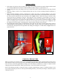
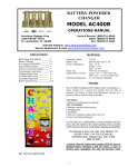
BATTERY OPERATED CHANGER
AC401
OPERATIONS MANUAL
American Changer Corp
1400 NW 65th Place
Ft. Lauderdale, FL 33309
Parts & Service: (888)741-9840
Sales: (800)741-9840
Fax: (954)917-5204
Internet Address: www.americanchanger.com
Service Questions?: E-mail: [email protected]
TABLE OF CONTENTS
Initial Setup
Charging the Battery
Filling the Coin Hopper
Hopper Coin/Token sizes
Using the Hopper Dump Feature
Indicator LED
Functional Description
Battery Specifications
SPECIFICATIONS
2
2-3
4
4
4
5
5-6
6
Operating Voltage:
Battery Type:
Power Consumption:
12V DC
Rechargeable Sealed Lead-Acid
Operating Max.: 13 W
Battery Life:
Supplied Battery Charger:
Sleep: 30 mW
8-10 Weeks on full charge
Charge: 14.8 – 15 Vdc, 550mA max.
Operating Temperature:
Float: 13.6 – 13.8 Vdc, 30mA
0 - 140 degrees Fahrenheit
WARRANTY
The AC401, including its Bill Validator and Coin Dispenser, is
under warranty for a period of 6 months from the date of
purchase. The battery is under full-replacement warranty for a
period of 30 days from the date of purchase.
COVERED:
¥ Defects in workmanship or materials
NOT COVERED:
¥ Damage caused by physical abuse
¥ Misapplication
¥ Vandalism
¥ End user’s attempt to repair unit on his own
¥ Lack of cleaning/maintenance
It is the End User’s responsibility to clean & maintain all their
parts. Any unit coming in for repair requiring only a cleaning
will be charged a flat rate of $65.00 plus shipping and
handling.
TO RETURN A PART OR UNIT FOR REPAIR, TO
ORDER A PART, OR FOR TECHNICAL
INFORMATION, PLEASE CALL TOLL FREE
(888) 741-9840
Rev. A 11.3.06
A Return Material Authorization number (RMA#) must be
obtained before returning a unit for repair. A copy of
invoices must accompany any and all warranty work.
1
INITIAL SETUP
1.
2.
3.
4.
5.
Fully unpack all of the boxes that accompany this changer. This should include the one that the changer and this manual
are in, and any additional boxes that may contain the Bill Box, Battery Charger, or spare batteries, etc.
Unlock and open the door to the changer. The keys to the door lock will be inside the manila envelope along with this
manual.
Inspect the changer’s interior for any shipping damage that may have occurred, including dislodged components or
connectors.
Before permanent installation, perform a functional test to further verify there is no shipping damage to your AC401
changer. To set up the changer, first connect the white two-position connector that is loose in the bottom of the cabinet to
the white connector attached to the top of the battery (refer to Figure 1 below). Ensure that the gray connector is fully
connected at the top of the hopper’s front face. Then, add some coins to the hopper, at least enough to cover the two
metal plates at the bottom of the Coin Bin, or approximately 100-150 coins. The changer is now ready for testing.
NOTE: the LED at the top of the hopper’s front face will blink every seven seconds or so while the changer is in Sleep
mode. If it is blinking faster, around once per second, there are not enough coins in the hopper (refer to Figure 4). Once
the changer has been tested and is working properly, continue with the remainder of the procedure.
Insert the Bill Box inside the changer. It should slide in on the right side of the cabinet, with its bottom resting on the two
studs protruding from the right interior wall, just above the battery. The part on the top of the Bill Box that sticks out
toward the left is designed to block accepted bills from falling into the hopper’s Coin Bin. Refer to Figure 2 below for
proper placement.
Connect
Bracket
Figure 1
Slide In
Figure 2
CHARGING THE BATTERY
When your AC401 arrives from the factory, the 12 Volt Sealed Lead Acid (SLA) battery supplied with the unit may not be
fully charged. In order to get the most use out of your changer, charge the battery fully before using the AC401 for the first
time. You can use either the supplied Battery Charger (ACC P/N AC400.4) or another one, as long as it complies with the
charging specifications detailed in the “Battery Specifications” section of this manual (refer to page 6).
Refer to the following procedure to charge the battery if using the supplied battery charger. If a different charger is to be
used, read the directions given here for removing and reinstalling the battery, and consult your charger’s manual for specific
charging instructions.
2
1.
2.
3.
Disconnect the battery from the Hopper Harness at the white connector located on top of the battery (refer to Figure 1).
Loosen the nut, and remove the bracket holding the battery in place (refer to Figure 1).
Slide the battery forward, and then pick it up and out of the cabinet.
NOTE: The battery should be charged in a well-ventilated area. Dot not charge the battery in an enclosed space.
4.
5.
With the battery charger unplugged, connect its white connector to the white connector fastened to the top of the battery.
NOTE: If your charger has alligator clips, attach the black one to the negative (-) battery terminal, and the red one to
the positive (+) terminal. In order for current to flow, the clips must make contact with the battery’s metal terminals, so
loosen, but do not remove, the Faston connectors if necessary.
Once the charger is properly connected to the battery, plug it in to any 120 Volt AC outlet to begin charging. During
charging, the RED “Charging” LED on the battery charger will be ON solid. Continue charging until the GREEN
“Charged” LED turns ON solid, at which time charging is complete (refer to Figure 3). Charging times depend on the
extent that the battery has been discharged, and may take up to 14 hours or more for a 100% discharged battery.
CAUTION! NEVER store a discharged battery for any length of time, as this leads to a condition inside the battery
called sufation, which may cause a permanent loss of battery capacity. ALWAYS fully charge the battery immediately
after use, recharging as often as is practicable, in order to prolong its service life.
6.
7.
8.
The supplied charger can remain connected to the battery and plugged in for any length of time without harm to the
battery.
When charging is complete, unplug the charger from the wall, and detach its connector from the battery.
Lift the battery back into the cabinet, and replace the metal bracket that holds it in place. Retighten the nut.
Reconnect the battery to the Hopper Harness at the white connector located on top of the battery.
Indicator
LED
Dump
Button
To
Remove
FIGURE 3 – SUPPLIED BATTERY
CHARGER
Bill
Meter
Figure 4
3
Coin
Bin
FILLING THE COIN HOPPER
The AC401 will not operate if the coin hopper is empty. There must be at least enough coins in the hopper to cover the two
gold-colored metal plates at the bottom of the Coin Bin for the changer to activate (refer to Figure 4). The hopper’s Coin Bin
can be filled while it is inside the changer, but it is recommended that you take the hopper out first, due to the relatively small
cabinet size. By default, the changer is programmed to dispense four coins per dollar from the hopper. These can be either US
quarters, or tokens or foreign coins valued at 25¢, as long as they are within the specified size limits detailed in the next
section of this manual. NOTE: Please contact American Changer if you have any questions regarding alternate payouts.
Hopper Coin/Token Sizes:
The standard American Changer Coin Hopper will accommodate coins ranging in size from 21 – 30 mm in diameter, and
from 1.25 – 3.3 mm in thickness. There are options available to dispense larger coins, up to 31.5 mm, and smaller coins,
down to 16.25 mm, in diameter. For reference, a Nickel is 21.2 mm, a Quarter is 24.3 mm, and Susan B. Anthony and
Sacagawea Dollar coins are 26.5 mm in diameter.
Hopper Removal, Filling, and Replacement:
1. Before removing the hopper from the cabinet, turn off the power by disconnecting the white connector from the top of
the battery (refer to Figure 1). Then, disconnect the gray connector from the top of the hopper’s front face.
2. Grasp the hopper, and slide it forward slowly, while gently applying upward pressure. Do not pull it all the way forward,
as far as it can go; by then it is too far. It should release from the hopper plate after moving only approximately 1 inch
forward.
3. Fill the hopper with coins; it can be filled all the way to the top. The hopper capacity in quarters is 1600 coins, +/- 10%
due to the random nature of coin piling inside of the bin. The hopper will be quite heavy when it is full, so take
additional care when installing it back inside the AC401 cabinet.
NOTE: Take care when filling the hopper to prevent any bent coins or foreign objects from entering the coin bin. These may
cause the coin hopper to jam, rendering the changer inoperable.
4.
5.
6.
Carefully lift the full hopper, and set it inside the changer on top of the hopper plate to the left of the battery. Make sure
the side with the LED, Bill Meter, and connector is facing forward, toward you.
The hopper plate has a keyed pattern along its sides that matches up with grooves on the underside of the hopper.
Maneuver the hopper on the plate by sliding it slightly forward and backward until its grooves line up correctly with the
keyed pattern, and it drops down into place on both sides. Then, slide the hopper backwards all the way until it stops to
lock it in place.
Reattach the gray connector to the top front of the hopper, and then reconnect the white two-position connector to the top
of the battery. The changer is now ready to use.
USING THE HOPPER DUMP FEATURE
A coin “Dump” is a convenient method of emptying all of the coins/tokens out of the hopper without having to remove the
hopper from the machine. Dumping the coins does not have any effect on the Bill Meter count.
♦
♦
To initiate a Dump: Press and hold the Dump Button until the hopper motor begins to run; it should commence after
approximately 3 seconds. Release the Dump button once the dispensing starts. The Dump button is located on top of the
front face of the coin hopper, to the right of the main connector (refer to Figure 4).
To terminate a Dump: The coin ‘dump’ can be stopped in either of two ways. Either A) Press the Dump Button once, or
B) Let the coins dispense until the hopper is completely empty; the motor will turn off automatically.
NOTE: Please be aware of the state of charge on the battery when performing a coin dump, and use caution. During a coin
dump, the hopper motor is run continuously, which discharges the battery at a much faster rate than normal operation of the
changer. Do not perform a coin dump using a battery that is already low, as over-discharging may damage it, shortening its
service life.
4
INDICATOR LED
The red Indicator LED is located on top of the front face of the coin hopper, to the left of the main connector (refer to Figure
4). This LED serves as a constant indicator as to the current status of the changer, and can be used for troubleshooting. The
following explains how to interpret the blinking of the Indicator LED:
♦
♦
♦
Slow (once every 7 seconds): A slow blink is the “heartbeat” indicator. This signifies that the changer is in Sleep Mode,
and is operating normally, waiting for a bill to enter the validator and “wake up” the changer.
Fast (once per second): A fast blink indicates an error has occurred, and the changer is out of service. In this state, the
validator will not accept bills. The two causes for this error code are as follows:
1. Low Coins – There are not enough coins left in the hopper to make contact with the two gold-colored metal
plates at the bottom of the coin bin. Once the hopper is refilled, the error will automatically be cleared.
2. Payout Error – An error of some sort, whether it is a coin jam, a mechanical or electronics failure, or similar,
has caused the hopper to mispay. Empty the hopper manually (not with the Dump feature), and inspect for a
coin jam or foreign object in the hopper. If nothing is found, disconnect and reconnect power at the battery, and
test the changer; the hopper may have failed.
No Blink: When the LED is not blinking at all, there is a power issue. The battery may be completely discharged. Check
the battery voltage using a Voltmeter; it must be above 10.5V for the changer to remain operational. If it is low, charge
the battery immediately (refer to the “Charging the Battery” section of this manual). If the battery is charged, check if the
Hopper Harness (P/N: AC400.1-H/NG) is damaged or discontinuous in any way, and inspect the fuse. The fuse is
located in the harness on top of the battery, in the red wire between the white two-position connector and the battery
terminal (harness P/N: AC400.11-H).
FUNCTIONAL DESCRIPTION
System Description:
The AC401 is a bill changer that accepts dollar bills and dispenses four quarters, in its standard configuration. It is also
programmable for various other coin/token payouts (Please contact American Changer with any inquiries).
Inside of the changer is a 12-Volt Sealed Lead-Acid (SLA) battery that powers the AC401’s complete operation. The battery
is connected through the Hopper Harness (P/N: AC400.1-H/NG) to the changer’s main logic controller board, which is
located inside the hopper. Also part of the changer is a 12-Volt bill validator that accepts $1 & $5 bills (only $1’s by default),
and the 12-Volt coin hopper that dispenses any coin or token within the size ranges detailed in the “Filling the Coin Hopper”
section of this manual.
A typical changing operation begins with a bill being inserted into the front of the bill validator. The changer is “awakened”,
and then the bill acceptor pulls the bill in, and examines it for authenticity. Once the bill has been “validated”, or deemed
genuine, it will then be pulled all the way into the machine. If the validator has a stacker, the bill will be pushed inside of it.
Stackerless models will eject the bills into the cabinet, where they should fall directly into the Bill Box. At this point, the
validator communicates to the Logic Board, via electronic pulses, the denomination of bill that was accepted. The Logic
Board reads the pulses, credits the money to its running total on the Bill Meter, and then turns on the coin hopper. The coin
hopper immediately begins to dispense coins, with the count being monitored by the Logic Board. When the correct number
of coins has been paid out of the hopper, according to the Logic Board’s programming, the hopper is turned off. If no bill is
again entering the front of the validator, the changer will then reenter Sleep Mode. This completes the changing operation.
Power Management:
The AC401 has two modes of operation with respect to its power usage, Standby and Sleep. Sleep Mode is the mode the
changer is in when there is no changing operation taking place, and the unit is “waiting” for a bill to be inserted into the
validator. During Sleep mode, power to the bill validator and the coin hopper is turned OFF, in order to conserve the battery.
Only one part of the system is ON and running, and that is the Main Logic Board, located inside the hopper, which controls
power distribution to the aforementioned peripherals.
Connected to the Main Logic Board, and also ON during Sleep mode, is an infrared optical sensor. Mounted on the inside of
the validator’s front bezel, the sensor is used to “wake up” the machine out of Sleep mode and bring it into Standby mode. A
bill being inserted into the validator first passes directly in front of the optical sensor, and immediately the electronics enter
5
Standby mode, where all of the peripherals are powered ON. Approximately one second later, after the bill acceptor has
finished its internal powering-up procedure, the bill will be pulled into the acceptor, validated, and the correct amount of
coins dispensed from the hopper. The power-up procedure is fast enough that a bill should be able to enter the front, pass by
the sensor to turn everything ON, and continue uninterrupted straight into the validator for processing.
The powering-down process for the validator occurs shortly after a successful bill validation, if the optical sensor has not
detected any additional bills. The hopper is powered down after is has completed the proper payout. The changer then
remains in Standby mode until the whole changing process is complete. If the sensor’s beam is blocked again by another bill,
the validator will be powered-on again, and the whole process will repeat. There is a short timer to shut off the system in the
case that the optical sensor detects something, but a bill is never successfully validated. Once all peripherals have been
powered OFF once again, the machine is returned to Sleep mode.
BATTERY SPECIFICATIONS
♦
♦
♦
♦
Operating Temperature Range: 0 °F (-18 °C) to 140 °F (60 °C)
Charging Temperature Range: 0 °F (-18 °C) to 122 °F (50 °C)
Cycle Charging: Limit initial current to 2.1A. Charge until battery voltage (under charge) reaches 14.4 to 15.0 volts at
68 °F (20 °C). Hold at 14.4 to 15.0 volts until current drops to approximately 70mA. Battery is fully charged under these
conditions, and charger should either be disconnected or switched to “float” voltage. NOTE: The supplied charger by
American Changer automatically switches to “float” voltage when the battery reaches a full charge.
“Float” or “Stand-By” Charging: Hold battery across constant voltage source of 13.5 to 13.8 volts continuously. When
held at this voltage, the battery will seek its own current level and maintain itself in a fully charged condition.
6