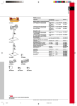
1
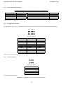
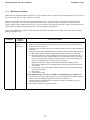
GENERATION I: M-150 Currency Validator OPERATION AND SERVICE MANUAL (Preliminary Copy) Back-Stack Family M-150 Operation and Service Manual Preliminary Copy IMPORTANT NOTICE Global Payment Technologies, Inc. (the Company), reserves the right to make changes to the contents of this publication, including functions and specifications identified herein, without notice. In the absence of a written agreement to the contrary, the Company, assumes no liability for the applications assistance, customer’s product/application/concepts, or infringements of patents or copyrights of third parties arising from the use of products methods and architectures described herein. Nor does the Company, warrant or represent that any license, either expressed or implied, is granted under any patent right, copyright, or other combination of technology, architecture, or software as might be or is already in use. Note: The material contained in this document is only intended for use by the Company, its employees and any licensed or authorized user of its proprietary products and/or software. The techniques, procedures and information described herein are Confidential Information and should not be reproduced, disseminated, or otherwise disclosed without prior written consent from an officer of the Company. Any authorized licensee or user specifically acknowledges that such techniques, procedures and information comprise valuable trade secrets and proprietary property of the Company and that all patent, copyright, trade secrets, trade/service mark, and any other right, title or interest therein are the sole property of the Company. This document has been copyrighted by the Company. The presence of any copyright notice within or upon the medium containing the Company's proprietary products shall not be construed as constituting any publication, any intention to publish or otherwise impairing the confidential nature thereof. 1995 Global Payment Technologies, Inc. 1 M-150 Operation and Service Manual Preliminary Copy TABLE OF CONTENTS 1 COMPANY INFORMATION .....................................................................................................................................................4 1.1 2 WARRANTY PROVISIONS....................................................................................................................................................5 INTRODUCTION.........................................................................................................................................................................6 2.1 2.2 2.3 3 M-150 ........................................................................................................................................................................................6 SBII ...........................................................................................................................................................................................6 FEATURES ...............................................................................................................................................................................6 THEORY OF OPERATION........................................................................................................................................................7 3.1 VALIDATION PROCESS ........................................................................................................................................................7 POWER UP FLOW CHART ...............................................................................................................................................................8 3.3 BLOCK DIAGRAM..................................................................................................................................................................9 4 INSPECTION AND SETUP.......................................................................................................................................................10 4.1 4.2 INSPECTION..........................................................................................................................................................................10 SETUP.....................................................................................................................................................................................11 4.2.1 Dip Switch..........................................................................................................................................................................11 4.2.2 Bench Testing.....................................................................................................................................................................11 4.2.3 Stand-alone Setup ..............................................................................................................................................................11 4.2.3.1 Performance test...............................................................................................................................................................................12 4.2.3.2 Acceptance test.................................................................................................................................................................................12 4.2.4 RS-232 Testing ...................................................................................................................................................................13 5 HARDWARE CONFIGURATION ...........................................................................................................................................13 5.1 5.2 5.3 6 MECHANICAL CONFIGURATION .....................................................................................................................................14 POWER APPLICATIONS ......................................................................................................................................................14 I/O CONNECTOR CONFIGURATIONS...............................................................................................................................14 5.3.1 Connecting the Credit Circuit............................................................................................................................................14 5.3.2 Connecting the Inhibit........................................................................................................................................................14 5.3.3 Connecting a Counter ........................................................................................................................................................14 5.3.4 Power and Credit Connections ..........................................................................................................................................15 5.3.5 Parallel Port Interface .......................................................................................................................................................15 5.3.6 Serial Port Interface...........................................................................................................................................................15 5.3.7 Stacker Port Interface ........................................................................................................................................................16 SOFTWARE................................................................................................................................................................................16 6.1 6.2 PROGRAM NUMBERING MATRIX....................................................................................................................................16 PROTOCOLS..........................................................................................................................................................................16 6.2.1 VFM4 / GL5 (SERIAL / PULSE)........................................................................................................................................17 6.2.2 GL5 RS232 .........................................................................................................................................................................17 6.2.3 RS232 (V1.X & V2.X).........................................................................................................................................................17 6.2.3.1 V1.X.................................................................................................................................................................................................17 6.2.3.2 V2.X (GPT ENHANCED SERIAL PROTOCOL) ..........................................................................................................................17 6.2.4 GPT High Level Pulse........................................................................................................................................................18 6.2.5 IGT Foreign & Domestic ...................................................................................................................................................18 6.2.6 Multi Drop Bus ..................................................................................................................................................................18 7 MAINTENANCE AND SERVICING .......................................................................................................................................18 7.1 MAINTENANCE .........................................................................................................................................................................18 7.1.1 Maintenance Schedule .......................................................................................................................................................19 7.2 SERVICING............................................................................................................................................................................21 7.2.1 Accessing The Currency Channel ......................................................................................................................................21 7.2.2 Video Level Adjustment......................................................................................................................................................21 7.2.3 Memory Clear Procedure ..................................................................................................................................................21 7.2.4 Magnetic Head Adjustment Procedure ..............................................................................................................................22 2 M-150 Operation and Service Manual Preliminary Copy 7.2.5 Belt Replacement ...............................................................................................................................................................22 7.2.6 Drive Belt Adjustment ........................................................................................................................................................23 7.2.6.1 DRIVE BELT ROUTING................................................................................................................................................................23 8 OPTIONAL LOCKABLE REMOVABLE CASSETTE (LRC) .............................................................................................24 8.1 STACKER OPTIONS .............................................................................................................................................................24 8.1.1 Dual Lock...........................................................................................................................................................................24 8.2 MAINTAINING THE STACKER ..........................................................................................................................................24 9 TROUBLESHOOTING..............................................................................................................................................................25 9.1 9.2 10 TABLE OF LED STATUS CODES........................................................................................................................................25 TROUBLESHOOTING CHART ............................................................................................................................................25 PARTS..........................................................................................................................................................................................27 3 M-150 Operation and Service Manual Preliminary Copy 1 COMPANY INFORMATION Corporate Office Global Payment Technologies, Inc. 20 East Sunrise Highway, Suite 201 Valley Stream, NY 11581 Phone:516-256-1000 Fax: 516-256-1620 Production Facility Global Payment Technologies, Inc. 425B Oser Avenue Hauppauge, NY 11788 Phone: 800-472-2506 or 516-231-1177 Fax: 516-434-1771 Figure 1 Corporate Offices Figure 2 Production Facility SALES OFFICES GPT - Las Vegas 6255 McLeod Drive Unit #8 Las Vegas, NV 89120 Phone:(702) 597-9660 Fax: (702) 597-9663 GPT - Southern Office GPT Beverage & Vending Division 621 Farr Shores Drive Hot Springs, AR 71913 Phone: (501) 262-0207 Fax: (501) 262-0657 GPT - South Africa Unit 26, Ground Floor Western Service Road The Woodlands Office Park Woodmead, South Africa Phone: 27-11-804-5025 Fax: 27-11-804-5026 GPT - UK Argyll House All Saints Passage London SW18 1EP England Phone:44-181-871-3566 Fax: 44-181-871-3858 GPT - Australia 844 Pacific Highway Gordon, New South Wales 2072 Australia Phone: 61-2-9499-3100 Fax: 61-2-9499-3048 Figure 3 Sales Offices 4 M-150 Operation and Service Manual Preliminary Copy 1.1 WARRANTY PROVISIONS GLOBAL PAYMENT TECHNOLOGIES, INC. EXTENDS THE FOLLOWING WARRANTY TO THE ORIGINAL PURCHASER OR ORIGINAL OPERATOR OF THE GPT CURRENCY VALIDATOR. ALL PARTS ARE GUARANTEED TO BE FREE OF DEFECTS IN MATERIAL AND WORKMANSHIP FOR A PERIOD OF ONE YEAR FROM DATE OF PURCHASE. GLOBAL PAYMENT TECHNOLOGIES, INC. AGREES TO REPAIR OR REPLACE, WITHOUT CHARGE DURING THE FOREGOING PERIOD, ANY PART WHICH PROVES DEFECTIVE UPON EXAMINATION BY GLOBAL PAYMENT TECHNOLOGIES, INC. ALL COSTS OF SHIPPING ANY ALLEGEDLY DEFECTIVE PARTS TO OR FROM THE OFFICES OF GLOBAL PAYMENT TECHNOLOGIES INC., SHALL BE BORNE BY THE ORIGINAL OPERATOR OR PURCHASER. IN CASE OF PARTS SUPPLIED TO GLOBAL PAYMENT TECHNOLOGIES, INC. AS COMPONENTS, GLOBAL PAYMENT TECHNOLOGIES, INC. EXTENDS THE SAME WARRANTY PERIOD AS EXTENDED BY THE ORIGINAL MANUFACTURER. THE ABOVE WARRANTY APPLIES PROVIDED THAT ALL PARTS OF THE MACHINE HAVE BEEN SERVICED PROPERLY AS DIRECTED IN THIS MANUAL AND PROVIDED THE ALLEGED DEFECTIVE PART, UPON EXAMINATION BY GLOBAL PAYMENT TECHNOLOGIES INC., SHALL PROVE THUS TO BE DEFECTIVE. THIS WARRANTY WILL NOT APPLY TO ANY VALIDATOR ON WHICH THE ELECTRONIC PCB ASSEMBLIES OR ANY OTHER PART HAS BEEN SUBJECT TO ANY MODIFICATION, ACCIDENT, ABUSE OR MISUSE. The warranty described in this paragraph shall be in lieu of any other warranty, express or implied, including but not limited to, any implied warranty or merchant’s ability or fitness for a particular purpose. There are no warranties which extend beyond the description on the face hereof. If this product does not perform as warranted herein, owner’s sole remedy shall be repair or replacement, at Global Payment Technologies, Inc. option. As further provided below, in no event will Global Payment Technologies, Inc. be liable for damages, lost revenue, lost wages, lost savings, or any incidental or consequential damages arising from purchase, use or inability to use this product, even if Global Payment Technologies, Inc. has been advised of the possibility of such damages. 5 M-150 Operation and Service Manual Preliminary Copy 2 INTRODUCTION 2.1 M-150 The M-150, also known as the M-IVO, is a completely self-contained currency validator, housed in a rugged sheet metal package. Inter-connection is quick and easy, and all parts for mounting and wiring are provided. A high level of validation and system security, combined with reliability and longevity, make the M-150 an ideal system for gaming and wagering, in the video lottery, pull tab, vending, and currency dispensing operations. 2.2 SBII SBII (Side Box II) is available from GPT. The SBII is an enclosure that can be mounted on the side or next to the host machine. This would allow the installation of the M-150 to be remote to the host machine thus no modification of the front panel of the host. This enclosure comes complete with all necessary hardware to make installation simple and easy provided that all requirements of the host machine and the M-150 are met (mechanical, power and interface). The optional SBII enclosure along with any necessary information is available from any GPT office. Some of the many standard features of the M-150 include: 2.3 • • • • • • • • • • • • • FEATURES One year warranty: Parts and labor Lightweight, self-contained assembly. Versatile power supply configurations: 115 VAC, 220 VAC, 24 Volts AC or DC and 12VDC Multi-Level high security validation process. Stacker or stackerless operation available in 500, 1000 and 2000 bill capacities. A secure Lockable Removable Cassette (LRC) with a one, two or no lock options. International currency validation capability. Consult factory for custom country applications. Accepts all U.S. denominations up to $100 bill. User selectable currency denomination acceptance. Variety of industry standard protocols. RS-232 Demo Kit. (Optional) A parallel port available for custom interface applications. Programming capable for flexible modifications to special or unique applications. (Settings stored in Non-Volatile Memory) 6 M-150 Operation and Service Manual Preliminary Copy 3 THEORY OF OPERATION 3.1 VALIDATION PROCESS Primary validation is conducted by the three infrared (IR) emitter and detector pairs. Transmissive optical techniques are utilized by the microprocessor through A/D and D/A converters. The light intensity of the IR emitters is controlled by the microprocessor. Secondary validation is accomplished by the utilization of two subsystems, the magnetic head and the spectral measurement circuit. Each system, primary and secondary, have equal importance, and individually or collectively initiate note rejection. A step-by-step outline of the validation process is described in the following steps: 1) Validator power up; power-on reset sequence begins. a) The red LED signal is visible at the channel insertion opening of the validator. b) Stacker operation is verified by running the stacker motor for 2 or 3 cycles. c) The CPU checks to see if there is a stacker attached. If no stacker is attached the CPU inhibits operation and sends a message to the host computer saying the stacker is not attached. SEE NOTE BELOW. d) The CPU enters an idle mode where the optical sensors are idle and the CPU is poling the front sensors for activity. NOTE: Not all programs operate the stacker. Most of the programs are stackerless and perform present/absent loopback. 2) Front sensor activated; bill inserted approximately 1” into the currency channel. a) The validator sends an RS-232 message to the host computer (in Active mode). This command acknowledges the beginning of the validation cycle. Infrared emitters are set to a predetermined calibrated level. The stepper motor starts which engages the bill drive transport. b) The CPU begins collecting and analyzing optical and magnetic data. c) Data collected is compared to a known database of programmed currency to determine bill validity and denomination. 3) Bill determined to be invalid; CPU begins the rejection routine. a) The CPU starts the stepper motor in reverse direction to reject the bill from the channel. The stepper motor drives the bill to the front of the channel and the CPU reenters the idle mode. b) If the bill transport cannot clear the channel, the CPU begins its channel clearing routine. This routine jogs the bill. This action effectively frees the bill resulting in the bill being returned to the customer. This routine is repeated for five (5) attempts. c) If during one of these attempts, the bill is successfully rejected, the validator reenters the idle mode. After the fifth attempt and the bill is unsuccessfully rejected, the CPU enters an inhibit routine. The jam must be cleared to come out of the inhibited state. This routine prohibits validator operation. d) If bill is cleared by the customer, the M-150 automatically recovers and returns to the idle state. 4) Bill determined to be valid; CPU acceptance routine begins. 1. The CPU repeats its sensor checking. 2. The rear currency channel flag is activated. This flag is used to: A. Signal the microprocessor that a bill has left the currency channel B. Determine the bill length for validation. NOTE: Credit is never issued until the currency is out of the validator. In the case where a stacker is used, the currency must first be stacked before credit is issued. The angular position of the flag permits the bill’s leading edge only, (forward motion) to raise the flag. In the stackerless models only a steel bar is attached to the flag which will help detect foreign substances attached to the bill. During the validation process the microprocessor will make decisions about the validity of the note presented. These decisions may be influenced by the selection of security levels one and two. The levels of security generally have no effect on the acceptance of notes in good condition however highly circulated notes may have a slight reduction in acceptance. A controller or host with an RS-232 serial port capability may remotely operate the M-150. Each note may be accepted or rejected by discretion of the remote controller or host. All options can be selected, as well as all credit information can be monitored. Additionally, the remote controller can disable other programming facilities such as DIP switch settings, memory stored configuration data, factory programmed serial numbers, and date of manufacture information. The memory also keeps a count of the total bills validated, which is useful for analysis during system repair. 7 M-150 Operation and Service Manual 3.2 Preliminary Copy POWER UP FLOW CHART Apply power to the bill validator Run the validator motor in reverse for 2 seconds CPU sets up all registers and I/O ports 3 times Yes No Check for the presence of the stacker loop CPU checks if DIP switch 9 is "on" No Yes Yes Check rear sensor for presence of a bill or debris Cycle the stacker 2 times No CPU enters service routine for Video Level Adjustment mode No Check middle optical sensor for presence of a bill or debris Yes CPU looks at the DIP switch for configuration information No Middle optic sensor and rear flag sensor clear Yes No Run validator motor in reverse for 2 seconds 1st attempt CPU looks for the "Set-Up" flag in the status register being set Run validator motor in reverse for 2 seconds 2nd attempt Yes Yes Prepare to enable the bill validator and send an eject message to the host machine Yes Run validator motor in reverse for 2 seconds 3rd attempt CPU interprets the configuration information stored in memory to be valid then sets the validator as per the memory stored configuration Make the appropriate configuration alternations Run validator motor in reverse for 2 seconds 4th attempt Run validator motor in reverse for 2 seconds 5th and final attempt Figure 4 Power-Up Flow Chart 8 Perfom Touch Memory test (read-write-read) GII ONLY Go to Idle M-150 Operation and Service Manual 3.3 Preliminary Copy BLOCK DIAGRAM The functional block diagram shown in Figure 5 depicts the blocks that comprise the M-150 currency validator. The Model M-150 consists of five (5) subassemblies which include the listed elements of the block diagram. 1. Main Assembly 2. CPU Assembly 3. Lower Guide Assembly 4. Upper Guide Assembly 5. Power Supply Assembly DC POWER +5, +12,+15VDC TO ALL DEVICES MAGNETIC AMPLIFIER SWITCHING AND LINEAR REGULATORS MAGNETIC HEAD BANDWITH FILTER AND AMPLIFIER VALIDATION OPTICAL DETECTORS 115/230 VOLT AC TRANSFORMER SPECTRUM DETECTOR 24 VOLT AC/DC POWER JACK POWER MONITOR CPU RESET CIRCUIT 8 OR 16 MHZ CPU CLOCK ANALOG TO DIGITAL CONVERTER SPECTRUM EMITTER 10 KHZ CARRIER GENERATOR VALIDATION OPTICAL EMITTERS DIGITAL TO ANALOG CONVERTER PROGRAM EPROM SERVICE SWITCH MICROPROCESSOR CURRENCY CHANNEL INPUT SENSOR OPTIO CUST INTER EMULA PARALLEL PORT CURRENCY CHANNEL REAR FLAG SENSOR OPTIONAL L DISPLAY VFM EMULATION INTERFACE USER PROGR DIP SWITC RS232 SERIAL INTERFACE OPTIONAL VALIDATOR DOLLAR COUNTER 12VDC ELECTROMECHANICAL STACKER POSITION SENSO RELAY (NO.) CREDIT PULSE OUTPUT STACKER CONTROL OPTO-ISOLATED INHIBIT-INPUT Figure 5 Block Diagram 9 STACKER MOTOR M-150 Operation and Service Manual Preliminary Copy 4 INSPECTION AND SETUP 4.1 INSPECTION Upon receipt and unpacking of the M-150 assembly, check unit for possible damage from shipping. If the shipping carton shows signs of damage, inspect unit immediately and report all damage to the carrier. Be sure to save all packing and boxes for any possible investigation. In the case of suspected damaged: 1. Ensure the unit has no bent or dented sheet metal. Check all mounting surfaces for “squareness” and free of damage. 2. Verify that there are no loose or broken components. A gentle “shaking” of the unit should disclose any internal damage. 3. Inspect unit for loose or missing hardware. There should be no loose covers or brackets. Report any discrepancies found. 4. Check all cables for cuts, nicks and other damage. Ensure all connections are intact and there are no bare wires. 5. Open stacker door and check the pressure plates for proper position. If necessary, realign the edge guides of the plates with the guide slots of the stacker housing. The plates should be aligned as shown. Stacker motor compartment Pusher plate Pressure plate Stacker plate Guide slots Stacker spring Stacker door hinge Figure 6 Stacker 10 M-150 Operation and Service Manual 4.2 Preliminary Copy SETUP 4.2.1 Dip Switch The validator is equipped with a single ten position DIP switch package. Refer to the program specific functions for each switch as detailed in the Program Specification sheets provided with the M-150 unit. Setting of the dip switch options to On or Off is illustrated in the following Figure 7. Typically, but not always, switches one through five are used for enabling/disabling the acceptance of various denominations. The M-150 must be reset after any changes are made to the switches in order for those selected changes to become active. It should be noted that it is also possible to change the configuration of the validator utilizing the RS-232 port with the M-150 installed in a networking environment or by utilizing the optional RS-232 Demo Kit. When making changes to the configuration utilizing the RS-232 port the command to save setup in non-volatile memory must be used in order to protect that setup information in the event of a power failure. This is only a typical dip BOTTOM OF VALIDATOR switch and does not represent any particular O FF setup or application ON 1 2 3 4 5 6 7 8 9 10 TOP OF VALIDATOR Figure 7 Dip Switch 4.2.2 Bench Testing The validator can be bench tested before its installation or at any desired time. It is recommended the bench test be performed before installation into the host machine. It is recommended the bench acceptance test or performance test be performed prior to servicing the validator, or sending the unit in for repair. The results of the bench acceptance test should be communicated to the GPT authorized repair facility to assist in diagnosing any fault with the product. 4.2.3 Stand-alone Setup Stand-alone bench testing, in some cases, will require a configuration setup that differs from that of normal operation. Because the majority of applications require a host controller to enable the bill validator, this enable will need to be duplicated by hardware intervention or in some cases, software intervention. To check to see if the current program in the bill validator posses the stand-alone capability, refer to the program name located on the label of the bill validator for the protocol designator. This can be easily done by locating the Protocol designator position of the software name and verifying that this position is occupied by the one of the following values: (0, 1, 2, 9, A, B, C, D, E, F, H, L, M & R). Refer to section 6.1 for a more detailed matrix of the program numbering system I S R X X X X X Protocol designator 11 M-150 Operation and Service Manual Preliminary Copy If it’s found that the program currently loaded in the bill validator does not possess the proper protocol designator as listed above, it will be necessary to perform one of the following: 1. Load a different program into the bill validator that does have the proper protocol designator. For M-150R this can be accomplished easily by utilizing the procedures outlined in the Serial Down-loader Manual which is readily available from any GPT office. For M-150, it will be necessary to exchange the Microprocessor with one having a program capable of bench testing. Questions regarding this should be forwarded to your local or closest GPT authorized service center. 2. Perform this testing with the bill validator installed within the host machine. 3. Duplicate the necessary enables and handshaking utilized in this particular application. Once the validator is loaded with the correct program, continue with the following steps: 1. 2. 3. 4. 5. 6. 7. 8. Refer to the DIP switch settings located on the program specification sheets for configuration information pertaining to HighLevel protocol mode. Position this DIP switch to the position that will enable the High-Level protocol mode (typically the “ON” position). Make the connection of an established appropriate power source as specified to the appropriate input power pins of the bill validator. Apply input power to the bill validator. The bill validator will run through a series of self-testing routines by which the bill validator motor will cycle followed by the stacker motor cycling (if used). After these routines have been successfully completed, the bill validator will become self-enabled. This can be confirmed by observing the status led blinking in accordance to the idle code listed on the program specification sheets. With the bill validator in the idle mode, you are now ready to perform your bench testing. If the above procedure does not result in the bill validator becoming enabled, it may be necessary to perform a memory clear procedure outlined in this manual then retry your steps starting with step #4. If the bill validator still will not become self-enabled, call your local GPT service center for assistance as specified in the Requesting Service section of this manual 4.2.3.1 Performance test This test is done to ensure that the validator is functioning in accordance to specification. • Insert two (2) bank notes of each denomination in each of the directions supported by the program. The validator should accept all the notes given within three (3) insertion attempts. Prior to any testing, perform a video level adjustment procedure. See the applicable section on performing this adjustment. 4.2.3.2 Acceptance test This test is used to assess the actual acceptance performance of the validator. This procedure is not normally performed due to the length of time involved and the amount of currency required. However, it is a useful tool in diagnosing performance issues, as well as determining program and machine performance. It may be abbreviated by using a single denomination in a single direction, which takes approximately 15 minutes. The following procedure is representative of current industry standard testing as well as how GPT performs acceptance tests. • • • Obtain one hundred bank notes representative of the, “in circulation quality”, of each denomination supported by the program. Start with the lowest denomination, and insert the notes one at a time, in a uniform (single) direction. Make one insertion attempt per note only. This is the “first attempt”. Record the number of notes that are rejected during the first attempt. Insert the rejected notes for a “second attempt” and record the number of rejected notes. The acceptance percentage for each attempt is the difference of 100 notes in the test, minus the rejected notes. 12 M-150 Operation and Service Manual Preliminary Copy Test result example: US $ 1 Direction A 100 Notes Acceptance • First Attempt Rejects 7 93% Second Attempt Rejects 3 97% Repeat the test for all denominations and directions supported by the program. WARNING: ANY VOLTAGE OTHER THAN THAT SPECIFIED IN THIS MANUAL CAN RESULT IN SEVERE DAMAGE TO THE UNIT AND/OR PERSONAL INJURY. REFER TO LABEL ON VALIDATOR. 4.2.4 RS-232 Testing An optional RS-232 Demo Kit is available from the factory. This kit includes the cable required to interface to a host computer and the software necessary to communicate with M-150 unit. The demo program is written in Visual Basic and will run on an IBM compatible PC. Features/functions are outlined in the RSDEMO manual available through any GPT office. 5 HARDWARE CONFIGURATION Figure 8 Validator & Stacker Drawing 13 M-150 Operation and Service Manual 5.1 Preliminary Copy MECHANICAL CONFIGURATION Figure 8 illustrates the mechanical-volume requirements and normal mounting position for utilizing the Model M-150 with a locking removable cassette. The drawing also identifies key electrical and mechanical areas/points on the assembly. Installation of the M-150 may require modification of the front panel of the host machine to facilitate the bezel. This can be accomplished by utilizing the available mounting hole pattern shown in the illustration provided in the appendix. Included in the appendix is an outline of the bezels, dimensions, hole patterns and hardware kits that can be provided with the M-150 units. 5.2 POWER APPLICATIONS Figure 9 outlines the pinout specifications utilized on the standard M-150 configuration. When powering the Model M-150 unit, it is not recommended (nor is it safe) to have two power cables coming out of the host machine. It is recommended that the M-150 unit be powered from an internal outlet or power source. The Model M-150 can be purchased in a variety of power source inputs. The possible power configurations support are listed below: a) 115 VAC, 50 / 60 Hz @ .15 Amps b) 12 VDC c) 24 VAC/DC, @ 1.0 Amps d) 24 VDC, @ 1.0 Amps e) 220 VAC, 50 / 60 Hz @ .10 Amps 5.3 I/O CONNECTOR CONFIGURATIONS The pinout configurations depicted in Figure 10 thru Figure 12 reflect signals and voltages at the header connectors of the validator and does not include any cable-end pinout configurations which are in most cases, customer specific. In the case where custom connector pinouts and types are utilized refer to the customer specific drawings provided with the unit or is readily available by contacting Global Payment technologies Inc. 5.3.1 Connecting the Credit Circuit The credit circuit consists of a normally open set of relay contacts. Therefore a wide range of voltages ranging from 0-115 volts may be used for the credit circuit. Connect the validator credit wires in parallel to the coin switch in the host machine or to the appropriate credit circuit. See Figure 9for the connector pinouts. Also available is an active low CPU output, fast credit signal. This signal is not buffered, and appropriate care must be taken not to excessively load the line, 5mA is the maximum drive capability. The signal is available on pin 5 of the parallel port, and as such, switch 6 of the DIP switch must be off. Be sure to connect to logic ground pin 1. Typically the timing is 50ms on and 50ms off, and will output credits as programmed with switches 7 and 8. Timing must be selected for output on this signal. 5.3.2 Connecting the Inhibit If the inhibit or lockout functions are required for your application, first determine the control voltage available from your machine. The validator power and interface cable have three connections dedicated to the inhibit function. The common connection should be connected to LOGIC GROUND. Do not connect this wire to the AC ground. The inhibit low voltage connection may be operated with a voltage between 5VDC and 24VDC. The inhibit high voltage should be limited to between 100V and 140V AC or DC. See Figure 9 for the connector pinouts. 5.3.3 Connecting a Counter An electromechanical counter may be connected to the validator. See figure for the appropriate pin numbers. The counter should be the type which requires 12VDC to drive. The validator will issue one count pulse for each dollar accepted (regardless of the credits per dollar selection). See Figure 9 Power and Credit Connections for the connector pinouts. 14 M-150 Operation and Service Manual 5.3.4 Preliminary Copy Power and Credit Connections POWER AND INTERFACE CONNECTOR PIN OUT CONFIGURATION COUNTER DRIVE INHIBIT LOW INHIBIT HIGH CREDIT SWITCH CREDIT SWITCH ORANGE WIRE RED WIRE BROWN WIRE BLUE WIRE GREEN WIRE INHIBIT COMMON AC HIGH, HOT OR DC GROUND AC LOW, NEUTRAL OR DC POSITIVE COUNTER +12VDC YELLOW WIRE BLACK WIRE WHITE WIRE GRAY WIRE Figure 9 Power and Credit Connections 5.3.5 Parallel Port Interface As illustrated in the figure below the parallel port may be used for a variety of interfaces, some of which must be specially ordered. 1 2 3 4 5 6 7 8 9 10 Figure 10 Parallel Port VFM4S 1. GND 2. INTERRUPT 3. ACCEPT EN 4. DATA 5. NC. 6. +5VDC 7. KEY 8. SEND 9. SERVICE 10. NC VFM4P 1. GND 2. NC 3. ACCEPT EN 4. SERIAL PROT. 5. NC 6. +5VDC 7. KEY 8. CREDIT 9. NC 10. NC VFM3 1. GND 2. NC 3. ENABLE 1$ 4. ENABLE 1$ 5. 1$ PULSE 6. +5VDC 7. KEY 8. ENABLE 5$ 9. ENABLE 5$ 10. 5$ PULSE Table 1 Parallel Port Pin Numbering 5.3.6 Serial Port Interface 1 2 3 4 5 6 Figure 11 Serial Port 1. GND 2. TD-RS232 3. TXD-TTL (See note below) 4. KEY 5. RD-RS232 6. RXD-TTL (See note below) Table 2 RS-232 Port Pin Numbering NOTE: RS232 IC chip must be removed when using the ttl interface. 15 M-150 Operation and Service Manual 5.3.7 Preliminary Copy Stacker Port Interface 1 2 3 4 5 6 7 8 9 10 Figure 12 Stacker Connector 1. GND. 5VDC 3. KEY 5. +15VDC 7. VLED 9. COUNTER DRIVER 2. NC 4. MOTOR DRIVER 6. LOCK SENSOR/MEM 8. POSITION SENSOR 10. +15VDC Table 3 Stacker Port Pin Numbering 6 SOFTWARE 6.1 PROGRAM NUMBERING MATRIX All new programs are to be numbered in conformance with the following system. The first two characters will be the ISO country code. The remaining six characters will be coded as follows; I S R X X X X X PROGRAM REVISION DATA BASE REVISION PROTOCOL SCHEMATIC NUMBER MACHINE TYPE RELEASE LEVEL COUNTRY ISO CODE Figure 13 Software Numbering Matrix 6.2 PROTOCOLS GPT makes available a number of industry standard communication protocols that are commonly utilized in the numerous types of validator applications. These applications range from vending to gaming. Because there are so many different types of applications for which GPT bill validators find themselves designed into, GPT has made considerable efforts to include as many standard and hybrid communication protocols into the hardware and software of our bill validators as possible. The M-150 bill validator has built into its hardware design, the most commonly utilized protocols along with some customer specific software that is available upon request. The following is a brief description of the most commonly utilized communication protocols available in the M-150 bill validator: 16 M-150 Operation and Service Manual 6.2.1 Preliminary Copy VFM4 / GL5 (SERIAL / PULSE) VFM4 Serial protocol provides a one way communication with the control system, that is, messages are transferred via the DATA line from the validator to a control system. Three control lines are used, they are: ACCEPT, SEND (from control system to validator), and INTERRUPT (from validator to control system). Two interfaces are furnished to permit the maximum versatility, one being the serial interface and other the pulse interface. This interface provides logic level (TTL/CMOS) serial communications between the validator and the controller using handshaking method. It allows the communication when a bill is recognized by the validator. The messages emerge in the order of an eight bit word. The interface utilizes one serial output line from the validator (DATA), and three control lines, two from the control system, ACCEPT ENABLE and SEND, and one from the validator, INTERRUPT. In addition GROUND should be connected from the validator to control system, i.e. both the validator and the control system should have common GROUND. The validator is continually in passive mode. When any event takes place within the validator, it will responds with a request to send message to the control system. As an example of one of this events could be bill being accepted by the validator. A complete manual for this communication protocol is available at GPT by request. 6.2.2 GL5 RS232 This communication protocol is the result of development by Mars (a bill validator and control board manufacturer) to create the next step beyond the VFM4 & GL5 protocols that are described above as being a one-way protocol. This protocol is a standard RS232 three wire format which runs at 300 baud. The command specification is that of Mars and is not proprietary to Mars. This protocol is not a recommended protocol because of its software limitation as well as the speed of the communication being only 300 baud. A complete manual for this communication protocol is available at GPT by request. 6.2.3 RS232 (V1.X & V2.X) 6.2.3.1 V1.X This protocol provides a 3 wire serial communication link between the validator and the host computer. This allows the user to monitor and/or control the validator activities. The link is flexible, allowing from no control to full remote control. This protocol is based on the standard serial message format used universally by IBM PC compatible computers. This format is one start bit followed by 8 data bits and one stop bit. Parity is used. The correct port setup is 9600 baud, 8 data bits, 1 stop bit and even parity. A cable connection can be made from the validator RS-232 port to the host computer serial port. The RS-232 protocol utilizes three lines for communication, transmit ( TXDATA ), receive ( RXDATA ) and a signal ground. These signals are +/- 12 VDC. The host computer must follow a specific set of rules to communicate properly with the validator. A complete manual for this communication protocol is available at GPT by request. 6.2.3.2 V2.X (GPT ENHANCED SERIAL PROTOCOL) The purpose of this protocol is to provide a reliable and robust communication link between the validator and the host machine controller. The protocol contains features designed to detect transmission errors and allow for the retransmission of data in case an error occurs. It also allows full access to the validator features and gives detailed information on the current state of the validator. Transmissions consist of message frames. Message frames are sent both by the controller and the validator. Acknowledge and IRQ bytes are sent only by the validator. The format of a message frame (below) consists of a start byte (STX), a length byte (LEN), a command / identifier byte (CMD), a number of data bytes between 0 and 251, and a check byte (CHK). A complete manual for this communication protocol is available at GPT by request. 17 M-150 Operation and Service Manual 6.2.4 Preliminary Copy GPT High Level Pulse This protocol is available for those applications that have only a simple control board or control mechanism available. This protocol is not recommended for those applications that wish to utilize the advance features of the generation II bill validator. With this protocol in effect, the M-150 will give Credit Pulses on the “NO” (Normally Open) contacts of the credit relay. The pulse timing is adjustable from 50ms on time, with 50ms off time, (50/50 Timing), to 60ms on time, with 300ms off time, (60/300 Timing). Each timing mode is selectable by a DIP switch selection or by RS-232 setup commands. 6.2.5 IGT Foreign & Domestic This protocol is utilized widely by GPT under contractual agreement with IGT and is recommended that you consult your bill validator factory for information on this protocol. 6.2.6 Multi Drop Bus This protocol better known as MDB is primarily used in the vending industry but can easily adapt itself to any application. This protocol utilizes a serial bus @ 9600 baud where up to thirty-two peripherals are able to be connected to the master controller. Each peripheral is assigned a unique address and command set. The master controller will "poll" the Bus for peripheral activity and each device will respond with an acknowledge, negative acknowledge, or specific data dependent on its current activity. A complete manual for this communication protocol is available at GPT by request. 7 MAINTENANCE AND SERVICING 7.1 Maintenance Periodically and depending on the particular environment, GPT bill validators may require some minor maintenance in order to bring the bill validator performance back within the specifications set by GPT. There are some conditions when present, will contribute to decreased bill validator performance in terms of bill acceptance. Below is a table of symptoms and conditions that if present will effect the performance of the bill validator along with applicable procedures to correct those conditions. An important step to minimize validator troubles is to read the instruction manual and program specification sheets. Most problems with currency validators are caused by seemingly innocent errors such as, incorrect DIP switch settings or foreign objects in the currency channel. 18 M-150 Operation and Service Manual 7.1.1 Preliminary Copy Maintenance Schedule Under normal use validators should be checked every 6 to 12 months, unless it is subjected to environmental extremes or is exposed to heavy doses of dirt, dust, water spray, airborne oil and sand. There are no potentiometers for the optical system adjustment, however, a reference video level has to be established for proper operation of the system. The video level adjustment procedure has to be undertaken any time maintenance is performed on the currency channel or if the validator appears to have a very low acceptance percentage (less than 85%). Refer to the following section of this operation and technical manual for instruction on how to calibrate and test the unit. The preventive maintenance consists of visual inspection and cleaning. Model M-150 has a simple access to the currency channel utilizing four thumb screws. Symptoms None Possible Condition General Periodic Maintenance Corrective Procedure 1) Perform whatever process necessary to obtain access to the bill validator. 2) Open the validator channel assembly exposing the optical system, magnetic head and rear flag assembly. See section 7.2 3) If compressed air is available, blow away any debris from the optical, rear flag and magnetic head area. 4) Using a soft lint-free cloth dampened with 90% isopropyl alcohol, clean the following areas: a) Bill channel surfaces on both the upper and lower guide to remove any surface dirt. b) Optical area utilizing a cotton swab dipped in the 90% isopropyl alcohol being sure to clean each and every optic, emitter and detector (top and bottom). It may be necessary to remove the optics array board in the event that the above prescribed cleaning in not effective in removing the dirt or debris built up on the optics. c) Magnetic head using soft lint-free cloth dampened with 90% isopropyl alcohol Removing any deposits from it’s horizontal surface while paying particular attention to any scratches. d) Pressure rollers on the upper guide assembly, using soft lint-free cloth dampened with 90% isopropyl alcohol. e) Belt surfaces. f) Front reflective sensor Caution should be used to prevent excess liquid from accumulating in the validator unit. 5) Check the action of the rear flag assembly. Action of the spring should be quick and snappy. 6) Perform video level adjustment procedure as prescribed in section 7.2.2 7) Perform stand-alone performance and or acceptance testing as prescribed in the in the “Bench Testing” procedure 4.2.2. 8) Return the bill validator to its operational state. Table 4 Periodic Maintenance Procedure 1 19 M-150 Operation and Service Manual Symptoms Poor Acceptance Possible Condition Dirty Optics Preliminary Copy Corrective Procedure 1) Perform whatever process necessary to obtain access to the bill validator. 2) Open the validator channel assembly exposing the optical system, magnetic head and rear flag assembly. (see section 7.2) 3) If compressed air is available, blow away any debris from the optical, rear flag and magnetic head area. 4) Using a soft lint-free cloth dampened with 90% isopropyl alcohol, Clean the following areas: a) Bill channel surfaces on both the upper and lower guide to remove any surface dirt. b) Optical area utilizing a cotton swab dipped in the 90% isopropyl alcohol being sure to clean each and every optic, emitter and detector (top and bottom). It may be necessary to remove the optics array board in the event that the above prescribed cleaning in not effective in removing the dirt or debris built up on the optics. c) Front reflective sensor Caution should be used to prevent excess liquid from accumulating in the validator unit. 5) Perform video level adjustment procedure as prescribed in section 7.2.2 6) Perform stand-alone acceptance testing as prescribed in the “Bench Testing” procedure 4.2.2 7) Return the bill validator to its operational state. Table 5 Periodic Maintenance Procedure 2 Symptoms Poor Acceptance Possible Condition Magnetic Errors Corrective Procedure 1) Perform whatever process necessary to obtain access to the bill validator. 2) Remove the bill validator from the host machine. 3) Utilizing GPT’s RSDEMO program and following the procedures outlined in the RSDEMO manual obtain the “Stats” (statistical information) from the bill validator. 4) Focusing on the error portion of the statistical information screen you can easily determine the major validator reported malfunction(s) by simply looking at the errors and the occurrence number of those errors compared to that of other errors and the occurrence number of those errors. 5) If you have determined that a majority of the errors are #07- “Fails Magnetic Tests”, while other reported errors are significantly less in comparison, it will be safe to say that there is some form of magnetic anomaly with the bill validator. 6) Having now determined that a magnetic anomaly exists, one of three steps must be taken: a) Perform the magnetic head adjustment procedure prescribed in the Magnetic Head Adjustment Procedure 7.2.4 followed by: b) Replace Magnetic Head board followed by i) Perform video level adjustment procedure as prescribed in the Video Level Adjustment Procedure 7.2.2 ii) Perform stand-alone performance and or acceptance testing as prescribed in the “Bench Testing” procedure 4.2.2 c) Return the bill validator to your Authorized Service Center. 7) Return the bill validator to its operational state. Table 6 Periodic Maintenance Procedure 3 20 M-150 Operation and Service Manual 7.2 SERVICING 7.2.1 1. 2. 3. 4. 5. 6. Preliminary Copy Accessing The Currency Channel Disconnect the validator power cable from the host machine. Remove the stacker from the validator. Remove the validator from the host machine. Remove bezel plate assembly from the validator. Disconnect (2) ribbon cable connectors on the side of the validator (side opposite to the stepper motor). (3) If a stacker is employed. Loosen the thumb-screws and separate upper and lower guide so the currency channel components are exposed. 7.2.2 Video Level Adjustment The video Level adjustment procedure calibrates the optical sensing circuitry. This procedure increases the digital to analog converter voltage on the emitter side until the proper level is read through the analog to digital converter. Paper densities differ for a given sample; therefore, measurements are taken 16 times. The average value is computed for each photo-element. The video adjustment procedure is one of the most important maintenance operations that can be performed on the validator and must be performed each time: 1. The validator is disassembled. 2. The optics are cleaned. 3. After a new program is loaded. 4. Before a performance test is made. To perform this procedure it is recommended that the GPT video level adjustment card be used for the best results. However, a piece of plain white copy machine paper (20lb bond), cut to the approximate size of currency will work temporarily. You will also need a sufficiently pointed, non-conducting object to depress the service switch. DO NOT USE A PENCIL. 1. 2. 3. 4. 5. 6. Disconnect power to the validator. Depress and hold the service switch, located near the DIP switch. Keeping the service switch depressed, power up the validator. Release the service switch. Insert the GPT video level adjustment card into the currency channel. The validator will first accept the GPT video level adjustment card into the currency channel about half way. The validator will then slowly step the paper out of the currency channel. When the paper is fully ejected, the video level adjustment is complete. The entire procedure takes about one minute. 7.2.3 Memory Clear Procedure The memory of the M-150 has the ability to have custom configuration data stored to it. This memory area may at some time become corrupt and require clearing so to allow proper configuration setup during the power-up sequence. If any of the following indications are exhibited in the bill validator, it may be necessary to clear the validator’s memory: 1. 2. 3. Bill validator was working fine and now will no longer accept bills Bill validator is performing or behaving out of the ordinary. Bill validator will not go to idle mode after power on cycle. 21 M-150 Operation and Service Manual Preliminary Copy To clear the memory, perform the following steps listed below: 1. 2. 3. 4. 5. 6. Apply power to the bill validator. Disconnect the stacker if one is being used. Locate the small service switch accessible through the small round cutout in the left side of the validator’s main housing. With a small non-metallic object similar to a toothpick or pencil tip, depress this service switch while monitoring the status led. The status led will change its blinking frequency from the original status reporting code to a fast blinking frequency indicating that memory has been successfully cleared. Cycle power to the bill validator. Reattach the stacker if one is used. 7.2.4 Magnetic Head Adjustment Procedure Objective of the magnetic head alignment / pressure roller adjustment procedure is to maximize the validator’s sensitivity to magnetic media. Many country currencies have bills with magnetic properties that with the aid of the magnetic circuitry greatly assists in recognition of legal currency while preventing the acceptance of counterfeits. 1. 2. 3. 4. 5. 6. 7. 8. 9. 10. 11. 12. 13. 14. 15. 16. 17. 18. 19. 20. 21. 22. 23. Remove the bezel. Disconnect two (2) ribbon cable connectors on the side of the validator (side opposite to the stepper motor). (3) If a stacker is employed. Loosen the thumb screws and separate upper and lower guide so the currency channel components are exposed . Remove the upper guide assembly from the power supply assembly. Remove the upper guide board to gain access to the magnetic head pressure spring, roller and adjustment nuts. Loosen the magnetic head pressure roller spring nuts. Carefully remove the magnetic head pressure roller. Make sure not to distort the original spring shape, as it may not apply enough pressure to the pressure roller. Adjust the spring so that the axis of the spring arms holding the pressure roller aligns with the magnetic head gap when viewed from the top. Tighten the magnetic head pressure roller spring nuts. Assemble the magnetic head pressure roller, making sure that the pressure roller does not touch sides of the slot when assembled Place clear scotch tape over the magnetic head. Mark the tape using permanent ink marker so that the magnetic head window is covered. Close the channel. Turn the magnetic head pressure roller forward and backwards a few times. Open the channel. Verify that the middle of the mark made by the pressure roller overlaps with the magnetic head gap. Repeat the procedure as necessary. Remove the scotch tape. Clean the magnetic head as necessary. Clean permanent ink marker contamination from the magnetic head pressure roller. Check for operation of the rear flag sensor. Replace the upper guide board. Reassemble the upper guide assembly onto the power supply assembly. Reassemble the bezel. Perform stand-alone performance and or acceptance testing as prescribed in the “Bench Testing” procedure 4.2.2. 7.2.5 Belt Replacement 1. Remove (LRC) Lockable Removable Cassette. 2. Disconnect Power/Interface Connector. 3. Remove Bill Validator from Mounting Bracket by loosening four hex nuts. 4. Disconnect cables from J1, J4, J21 and J23. 5. Loosen the (4) 6/32” thumb screws. 6. Separate the upper and lower assemblies. 7. Remove the (4) 6-32 large philip panhead screws on the lower assembly. *TECH HINT* If you loosen the 4-40 x 3/16 screws on the sides of the lower unit, it will ease the separation of the lower guide plate from the lower main assembly. 22 M-150 Operation and Service Manual Preliminary Copy **CAUTION** Be careful when separating the lower guide from lower main assembly, possible damage could occur to ribbon cable connector. 8. Remove the lower guide plate. 9. Disconnect ribbon cable J-40 from lower guide PCB. 10. Loosen hex nut on idler bracket. 11. Loosen tension on belt by adjusting idler bracket. 12. Remove drive belt from molded pulley and motor assembly. 13. To remove the drive belt from molded pulley on the opposite side, simply roll drive belt off of molded pulley. 14. Remove drive shaft assembly and replace belts. (To re-assemble follow same procedure in reverse) 7.2.6 Drive Belt Adjustment *NOTE* Both Belts must have the same tension to avoid skewing of bill during bill validation. 1. Loosen hex nut on the idler bracket. 2. Adjustment is made by raising or lowering idler bracket. 3. Once correct tension is set, re-tighten hex nut to secure. 7.2.6.1 DRIVE BELT ROUTING MOTOR DRIVE SIDE IDLE SIDE 23 M-150 Operation and Service Manual Preliminary Copy 8 OPTIONAL LOCKABLE REMOVABLE CASSETTE (LRC) The M-150 has available as optional equipment a lockable and detachable stacker (LRC). The stacker is offered in three capacities, 500, 1000 and 2000 bill sizes. See Application note 00005 for mounting and dimensional information of the complete assembly. The stacker comes complete with a high security tubular type key. The validator and stacker combinations are easily mounted together with a swinging action. Installation of the stacker is accomplished by simply placing the pins of the LRC onto the stacker hinge bracket of the M-150. Swing the LRC assembly until it mates with the connector and latch on the validator. All electrical connections are automatically made with the connecting of the validator and stacker. Removal is accomplished by lifting the rear of the stacker approximately 15 degrees off the horizontal and lifting the stacker away from the validator head while depressing connector latch. Refer to Figure 8. If the M-150 was purchased without a stacker, and it is found necessary to have one at a later date, any of the above stackers can be ordered from GPT. The stacker, when ordered separately, requires the installation of the stacker hinge and connector bracket. All parts and hardware are supplied with the stacker. (At the time of ordering, please note that you have a stackerless unit) Refer to application note 00005 when attempting to install the optional stacker to your M-150. Also if your M-150 has an optional security flag it must be changed in order to correctly accommodate the stacker. 8.1 8.1.1 STACKER OPTIONS Dual Lock The stacker has available a dual lock door assembly intended for high security “buddy system” applications. The locks are the “T” latch type which mate into a special bracket inside the stacker. The kit is supplied with two locks, stacker door and all mounting hardware. 8.2 MAINTAINING THE STACKER Little maintenance is required on the stacker. Cleaning the currency dust and dirt out of the stacker with air will prevent the optical sensors from becoming inoperative. This is accomplished by opening the rear door and blowing air into the back of the LRC and then into front bill entry path to expel any debris. CAUTION: ALWAYS WEAR EYE PROTECTION WHEN USING COMPRESSED AIR. The pusher plate and cam pin should be lubricated, sparingly, with white lithium grease periodically. Occasionally during transportation when the stacker is empty, the spring plate may become dislocated from the normal operating position. Open the rear door and relocate the plate tabs into the cutout guides on the stacker body. 24 M-150 Operation and Service Manual Preliminary Copy 9 TROUBLESHOOTING This section lists the possible causes and suggested solutions for a series of common and not-so common validator ailments. The suggested solutions are not meant to be definitive, but they should help to pinpoint a problem in your unit. The model M-150 currency validator has a status LED that will give the current machine status by blinking the specific code. The LED will flash 1/4 sec. on, 1/4 sec. off with a two second pause between codes. The idle code is 1 or 3 depending on the software revision installed. After accepting the note, the LED code shows what denomination was accepted as the last one (1 through 5). After rejecting the note, error codes are from 8 to 18. (Refer to table below.) 9.1 TABLE OF LED STATUS CODES TABLE OF LED STATUS CODES FLASHING LED CODE (after bill is accepted) 1 or 3-- Idle Mode 1-- After bill is accepted 2-- After bill is accepted 3-- After bill is accepted 4-- After bill is accepted 5-- After bill is accepted 6-- After bill is accepted 7-- After bill is accepted 9.2 DESCRIPTION Normal Valid $1 Valid $2 Valid $5 Valid $10 Valid $20 Valid $50 Valid $100 FLASHING LED CODE (after bill is rejected) 8-- After bill is rejected 9--After bill is rejected 10-- After bill is rejected 11-- After bill is rejected 12-- After bill is rejected 13-- After bill is rejected 14-- After bill is rejected 15-- After bill is rejected 16-- After bill is rejected 17-- After bill is rejected 18-- After bill is rejected DESCRIPTION Bill Inhibited Not used Not used Unable to pass to chamber Not used All bills inhibited Maximum credit stored Unable to stack All bills inhibited by RS-232 Unable to stack Fails high security test TROUBLESHOOTING CHART TROUBLESHOOTING CHART SYMPTOM NO LED, NO MOTOR ACTION. LED “ON” ALL THE TIME, NO MOTOR ACTION. PROBABLE CAUSE • • • • • • • • LED CODE: 1 OR 3 NO MOTOR ACTION LED CODE: 13, NO MOTOR ACTION • • • • POWER CABLE NOT CONNECTED POWER SUPPLY RIBBON CABLE INCORRECTLY INSTALLED DEFECTIVE POWER SUPPLY (CHECK FOR BROKEN TRANSFORMER PINS, BLOWN FUSE, SHORTED DIODE D80, DEFECTIVE 15V SWITCHING REGULATOR) BENT PINS IN POWER CABLE INTERFACE CONNECTOR INCORRECT VOLTAGE SUPPLIED IC DALLAS 1233 (RESET) DEFECTIVE MICROPROCESSOR DEFECTIVE FRONT SENSOR DEFECTIVE (CHECK FRONT SENSOR OUTPUT SIGNAL ON SCHMITT-TRIGGER (PINS 3 AND 4) AND ON MICROPROCESSOR (LED 3) OR DIRECTLY ON THE FRONT SENSOR VOLTAGE ON THE INHIBIT LINE (FROM THE HOST MACHINE) POWER SUPPLY RIBBON CABLE CONNECTOR INCORRECTLY INSTALLED DIP SWITCH 10 IN WRONG POSITION (NORMALLY SHOULD BE OFF; REFER TO THE PROGRAM SPECIFICATION SHEET OF THE SOFTWARE INSTALLED IN THE VALIDATOR) POSSIBLE CONFIGURATION CORUPTION STORED IN MEMORY. TRY CLEARING MEMORY AS PER SECTION 7.2.3N THIS MANUAL. 25 M-150 Operation and Service Manual Preliminary Copy TROUBLESHOOTING(continued) TROUBLESHOOTING CHART SYMPTOM PROBABLE CAUSE • LED CODE: 7, POOR ACCEPTANCE RATE LED CODE: 8, NO ACCEPTANCE LED CODES: 9 AND 13, POOR ACCEPTANCE RATE • • OPTICS REQUIRE VIDEO LEVEL ADJUSTMENT AND/OR CLEANING AS PER SECTION 7.2.2 IN THIS MANUAL. LOWER PCB DEFECTIVE UPPER PCB DEFECTIVE IN ALL THREE CASES CHECK OUTPUT SIGNAL OF INFRA-RED RECEIVERS ON A/D CONVERTER (LEGS 3,4,5) BILL INHIBITED BY DIP SWITCH MAGNETIC HEAD DIRTY MAGNETIC HEAD OR AMPLIFIER DEFECTIVE. CHECK MICROPROCESSOR (LEG 33) FOR MAGNETIC HEAD PULSES WHILE TRYING TO VALIDATE A BILL. CHECK RESISTANCE BETWEEN LEGS OF MAGNETIC HEAD. READINGS SHOULD BE: 370-600 OHMS FOR THE HEAD TO BE GOOD. IF READINGS ARE 1K OHMS OR MORE THE MAGNETIC HEAD IS BAD. SPECTRAL MEASUREMENT CIRCUITRY FAILURE. CHECK BLUE LIGHT RECEIVER OUTPUT SIGNAL ON A/D CONVERTER (LEG 6) REPLACE BLUE LED OR UPPER PCB ASSY. IF NECESSARY. PERFORM VIDEO LEVEL ADJUSTMENT AS PER SECTION 7.2.2 IN THIS MANUAL. STACKER IS FULL OF BILLS PRESSURE PLATES NOT IN CORRECT POSITION. GREASE ON STACKER OPTICAL SWITCH STACKER OPTICAL SWITCH DEFECTIVE (CHECK SIGNAL ON MICROPROCESSOR (LEG 15) INCORRECT BELT TENSION INCORRECT DRIVE ROLLERS SPRINGS TENSION • • • • • • CIRCUIT WIRES BROKEN FET BS170 DEFECTIVE POWER SUPPLY RIBBON CABLE INCORRECTLY INSTALLED FOREIGN OBJECT IN THE CURRENCY CHANNEL INCORRECT BELT TENSION INCORRECT DRIVE ROLLER SPRING TENSION • • • • • • • • LED CODE: 15 POOR ACCEPTANCE RATE • LED CODE: 17 NO MOTOR ACTION STACKER PUSHER PLATE STOPS IN WRONG POSITION (CAUSES JAMS) BILLS ARE PULLED TO THE SIDE OF THE CURRENCY CHANNEL NO CREDIT PULSE ISSUED FREQUENT JAMS • • • • 26 M-150 Operation and Service Manual Preliminary Copy 10 PARTS MAIN ASSY. BRACKET HINGE FOR STACKER BRACKET HINGE FOR STACKER CHASSIS ASSY INSEP. (SHEET METAL W/ POSTS) CHASSIS ASSY INSEP. (SHEET METAL W/ POSTS) DRIVE BELT DRIVE BELT (MOTOR SIDE) DRIVE SHAFT DRIVE SHAFT DRIVE SHAFT BUSHING GREASE LITHIUM WHITE HEX NUT KEPS #4-40 IDLER BRACKET ASSY INSEP (SHEET METAL W/ POSTS) IDLER BRACKET ASSYBRACKET ASSY (COMPLETE) MOTOR PULLEY PULLEY, MOLDED RETAINING CLIP 0.125 RETAINING CLIP 0.187 ROLLER, IDLER GROOVED SCREW TRUSSHEAD 6-32 x 1/8 SCREW, PANHEAD #4-40 x 11/16 SCREW, PANHEAD #4-40 x 7/16 SCREW, PANHEAD, SEMS 4-40 x 3/16 STEPPER MOTOR (16 OHM) (NARROW) AIRPAX GPT PART NUMBERS 289-B-0200 176-B-0004 176-B-0100 208-9580-0007 208-1008-0008 360-A-0005-2 360-B-0007 206-A-0002 261-0001-0001 306-0001-0440 176-A-0001 180-A-0002 289-B-0149 260-B-0012 324-0002-0002 324-0002-0001 289-A-0547 352-0632-0002 352-6875-0104 352-4437-0101 352-4187-0116 299-B0004 27 QTY PER ASSY. 1 1 1 1 1 1 1 1 AS REQ 4 1 1 1 6 4 6 2 4 2 6 4 MODEL VERSION ( 150-A, 150-C, 150-BB, 150-A/ADP, 150-BB/ADP ) 150BB, BB-ADP 150-A/C, A/ADP 150-A/C, A/ADP 150-BB, BB/ADP 150-A/C/BB,A/BB-ADP 150-A/C/BB,A/BB-ADP 150-A/C, A/ADP 150BB, BB-ADP 150-A/C/BB,A/BB-ADP 150-A/C/BB,A/BB-ADP 150-A/C/BB,A/BB-ADP 150-A/C, A/ADP 150-A/C, A/ADP 150-A/C/BB,A/BB-ADP 150-A/C/BB,A/BB-ADP 150-A/C/BB,A/BB-ADP 150-A/C/BB,A/BB-ADP 150-A/C/BB,A/BB-ADP 150-A/C/BB,A/BB-ADP 150-A/C/BB,A/BB-ADP 150-A/C/BB,A/BB-ADP 150-A/C/BB,A/BB-ADP 150-A/C/BB,A/BB-ADP M-150 Operation and Service Manual UPPER GUIDE ASSY. DRIVE ROLLER DRIVE ROLLER PRESSURE SPRING FLAG FLAG ASSY (COMPLETE) FLAG BRACKET ASSY. FLAG SPRING HEX NUTS KEPS #4-40 MAGNETIC HEAD PRESSURE ROLLER MAGNETIC HEAD PRESSURE ROLLER SPRING MAGNETO-RESISTIVE HEAD PRESURE ROLLER RETAINING CLIP THUMB SCREW #6-32 UPPER GUIDE (SHEET METAL W/ POSTS) UPPER GUIDE (SHEET METAL W/ POSTS) LOWER GUIDE ASSY. LOWER GUIDE (SHEET METAL W/ POSTS) LOWER GUIDE (SHEET METAL W/ POSTS) LOWER GUIDE (SHEET METAL W/ POSTS) REAR DEFLECTOR SCREW, PAN HEAD 4-40 x 1/8 Preliminary Copy GPT PART NUMBERS 328-0030-0002 364-0037-0008 190-0037-0004 180-A-0001 176-A-0003 364-0037-0007 306-0001-0440 328-A-0004 364-A-0002 328-A-0007 324-0002-0002 354-0030-0004 289-C-0111 289-C-0172 GPT PART NUMBERS 289-C-0113 289-C-0114 289-C-0171 289-A-0410 352-0440-0002 28 QTY PER ASSY. MODEL VERSION 6 6 1 1 1 1 4 1 1 1 3 4 1 1 150-A/C/BB,A/BB-ADP 150-A/C/BB,A/BB-ADP 150-A/C/BB,A/BB-ADP 150-A/C/BB,A/BB-ADP 150-A/C/BB,A/BB-ADP 150-A/C/BB,A/BB-ADP 150-A/C/BB,A/BB-ADP 150-A/C/BB,A/BB-ADP 150-A/C/BB,A/BB-ADP 150-A/C/BB,A/BB-ADP 150-A/C/BB,A/BB-ADP 150-A/C/BB,A/BB-ADP 150-A/C, A/ADP 150BB, BB-ADP QTY PER ASSY. MODEL VERSION 1 1 1 1 2 150-A, A-ADP 150-C, C-ADP 150-BB, BB-ADP 150-A/C/BB 150-A/C/BB,A/BB-ADP ( 150-A, 150-C, 150-BB, 150-A/ADP, 150-BB/ADP ) ( 150-A, 150-C, 150-BB, 150-A/ADP, 150-BB/ADP ) M-150 Operation and Service Manual MAIN BOARD ASSY. CIRCUIT BOARD STANDOFF .250 x 7/16 MAIN ELECTRONICS CHASSIS (SHEET METAL W/ POSTS) MAIN ELECTRONICS CHASSIS (SHEET METAL W/ POSTS) SCREW, PAN HEAD 4-40 x 11/16 SCREW, PAN HEAD 4-40 x 3/6 STACKER STACKER LATCH CABLE ASSY STACKER LATCH ASSY W. CABLE SCREW, PAN HEAD 6-32 x 1/4 SCREW, FLAT HEAD 4-40 x 3/8 HEX NUT, KEPS 4-40 x 3/8 POWER SUPPLY POWER SUPPLY CHASSIS TRAY (SHEET METAL W/ POSTS) POWER SUPPLY CHASSIS TRAY (SHEET METAL W/ POSTS) POWER SUPPLY HOUSING (SHEET METAL W/ POSTS) POWER SUPPLY HOUSING (SHEET METAL W/ POSTS) POWER SUPPLY HOUSING (SHEET METAL W/ POSTS) POWER SUPPLY HOUSING (SHEET METAL W/ POSTS) SCREW, FLAT HEAD 4-40 x 1/8 SCREW, PAN HEAD 4-40 x 3/16 SCREW, PAN HEAD SEMS 4-40 x 3/16 Preliminary Copy GPT PART NUMBERS 362-1127-0012 289-B-0153 289-B-0174 352-6875-0104 352-4187-0102 GPT PART NUMBERS 172-B-0007 172-B-0008 352-6250-0125 352-4375-0130 306-0001-0440 GPT PART NUMBERS 289-B-0127 289-C-0175 289-C-0121 289-C-0173 289-C-0185 289-C-0758 352-4125-0113 352-4187-0102 352-4187-0116 29 QTY PER ASSY. MODEL VERSION 2 1 1 2 2 150-A/C/BB,A/BB-ADP 150-A/C, A/C-ADP 150-BB, BB-ADP 150-A/C/BB,A/BB-ADP 150-A/C/BB,A/BB-ADP QTY PER ASSY. MODEL VERSION 1 1 2 2 2 150-A/C/BB 150-A/C/BB 150-A/C/BB,A/BB-ADP 150-A/C/BB,A/BB-ADP 150-A/C/BB,A/BB-ADP QTY PER ASSY. MODEL VERSION 1 1 1 1 150-A/C 150-BB 150-A/C 150-BB 150-BB-ADP 150-A/C-ADP 150-A/C/BB,A/BB-ADP 150-A/C/BB,A/BB-ADP 150-A/C/BB,A/BB-ADP 1 2 10 7 ( 150-A, 150-C, 150-BB, 150-A/ADP, 150-BB/ADP ) ( 150-A, 150-C, 150-BB, 150-A/ADP, 150-BB/ADP ) ( 150-A, 150-C, 150-BB, 150-A/ADP, 150-BB/ADP ) M-150 Operation and Service Manual CABLES LOWER GUIDE TO CPU BOARD RIBBON CABLE MAIN BOARD TO STACKER POWER SUPPLY TO MAIN BOARD RIBBON CABLE UPPER GUIDE TO LOWER GUIDE RIBBON CABLE MICROPROCESSORS 52 WINDOW/EPROM 52-OTP (ONE TIME PROGRAM) 528 WINDOW/EPROM 528-OTP (ONE TIME PROGRAM) Preliminary Copy GPT PART NUMBERS 172-A-0002 172-B-0102 172-A-0003 172-A-0001 GPT PART NUMBERS 348-52EB-0027 348-87C5-0020 348-528E-0023 348-C528-0021 30 QTY PER ASSY. MODEL VERSION 1 1 1 1 150-A/C/BB,A/BB-ADP 150-A/C/BB-ADP 150-A/C/BB,A/BB-ADP 150-A/C/BB,A/BB-ADP QTY PER ASSY. MODEL VERSION 1 1 1 1 150-A/C/BB,A/BB-ADP 150-A/C/BB,A/BB-ADP 150-A/C/BB,A/BB-ADP 150-A/C/BB,A/BB-ADP ( 150-A, 150-C, 150-BB, 150-A/ADP, 150-BB/ADP ) ( 150-A, 150-C, 150-BB, 150-A/ADP, 150-BB/ADP )