1
III. Step 3
Turn off the electrical power supply to the unit.
IV. Step 4
Remove the front access panel.
V. Step 5
Move the selector switch on the internal gas valve to the OFF
position.
VI. Step 6
Replace the front access panel.
VII. Step 7
Restore electrical power to the unit and set system switch to
COOL to ensure operation of the cooling system during the
cooling season.
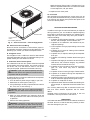
Fig. 2 — Gas Heating/Electric Cooling Unit
(Internal View)
ROUTINE MAINTENANCE
All routine maintenance should be handled by skilled, experienced personnel. Your dealer can help you establish a standard procedure.
For your safety, keep the unit area clear and free of combustible materials, gasoline, and other flammable liquids and
vapors.
To assure proper functioning of the unit, flow of combustion
and ventilating air must not be obstructed from reaching the
unit. Clearance of at least 30 in. is required on all sides except the duct side.
If you have difficulty in locating your air filter(s), or if you
have questions concerning proper filter maintenance, contact your dealer for instructions. When replacing filters, always use the same size and type of filter that was supplied
originally by the installer.
Table 1 — Indoor-Air Filter Data*
UNIT SIZE
582A018-030
582A036-042
582A048-060
583A024-030
583A036
583A042-060
MAINTENANCE AND CARE FOR THE
EQUIPMENT OWNER
Before proceeding with those things you might want to maintain yourself, please carefully consider the following:
WARNING:
1. TURN OFF GAS SUPPLY AND ELECTRICAL
POWER TO YOUR UNIT BEFORE SERVICING OR
PERFORMING MAINTENANCE.
FILTER SIZE
20x24
20x24
24x30
20x20
20x24
24x30
*For filter grille installations only.
WARNING: Never operate your unit without filters
in place. Failure to heed this warning may result in damage to the blower motor and/or compressor. An accumulation of dust and lint on internal parts of your unit
can cause loss of efficiency and, in some cases, fire.
2. Do not turn off electrical power to this unit without
first turning off the gas supply.
3. When removing access panels or performing maintenance functions inside your unit, be aware of sharp
sheet metal parts and screws. Although special care
is taken to reduce sharp edges to a minimum, be extremely careful when handling parts or reaching into
the unit.
II. Heat Exchanger
To ensure dependable and efficient heating operation, the heat
exchanger should be checked by a qualified maintenance person before each heating season, and cleaned when necessary.
This checkout should not be attempted by anyone not having
the required expertise and equipment to properly do the job.
Checking and/or cleaning the heat exchanger involves removing the gas controls assembly and the flue collector box cover
and, when completed, reinstalling the gas controls assembly
for proper operation. Also, the flue collector box cover must
be replaced correctly so that a proper seal is maintained. Contact your dealer for the required periodic maintenance.
I. Air Filters
Air filter(s) should be checked at least every 3 or 4 weeks and
changed or cleaned whenever it becomes dirty. Dirty filters
produce excessive stress on the blower motor and can cause
the motor to overheat and shut down. Table 1 indicates the
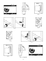
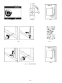
correct filter size for your unit. Refer to Fig. 5 to access the
filter(s).
To replace or inspect filter(s) (or accessory filter rack when
supplied):
1. Remove the filter access panel using a 5⁄16-in. nut driver.
2. Remove the filter(s) by pulling the filter(s) out of the unit.
If the filter(s) is dirty, clean or replace with new one.
When installing the new filter(s), note the direction of the airflow arrows on the filter frame.
III. Fans and Fan Motor
Periodically check the condition of fan wheels and housings and fan-motor shaft bearings. No lubrication of
condenser- or evaporator-fan bearings or motors is required
or recommended.
IV. Evaporator and Condenser Coils
Cleaning of the coils should only be done by qualified service
personnel. Contact your dealer for the required annual
maintenance.
—3—