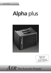
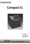
1
user manual amp one r Register you amp one: ps.com www.aer-am rvice Se > Customer 1 amp one user manual Contents 2 Page 1. Introduction 3 2. Safety Instructions 4 3. Controls and Connections 4 3.1 Front Side 4 3.2 Rear Side 5 4. Starting-up 6 4.1 Cabling and Switching-on 6 4.2 Level Adjustment 6 5. Functional Characteristics 7 5.1 Mute 7 5.2 Tone Control Networks 7 5.2.1 colour 7 5.2.2 bass boost 7 5.2.3 parametric equalizer 5.2.4 tone balance 5.3 Compressor 8 5.4 Rear Side Features 9 7 7-8 6. Technical Specifications 10 7. Circuit Diagram 11 1. Introduction Welcome to B! Thank you for choosing the amp one out of the AER bottom-lineseries. This series has been specially developed for the modern bass player who values performance, versatility and easy handling. Please take a few minutes to read through these instructions. We want you to understand just what the amp one can do and how to set it up so that you can get maximum benefit out of it. The amp one is an „all-rounder“, designed for the „Top 40“ bassist who is used to switch between several styles and who sets value on weight, dimensions and easy operation. The 10-inch high performance bass-loudspeaker supports this versatility whilst simultaneously adding some tube-like compression. The design of the power-amp especially supports the impulse response and provides impressive power at short term, exceeding significantly the specified 200 W on 8 ohm, which you can clearly hear. Amp one is professionally and richly equipped and, of course, it produces the unmistakeable AER sound character. Technically speaking, the amp one is designed for high-impact and extreme dynamics. From the musical point of view, the bass combo is clear, differentiated, assertive, punchy and inspiring. At this point we would like to thank Paul Sips for his „final blessings“. Read on and have fun with your amp one! 3 2. Safety Instructions The following instructions help to minimize the risk of injury through fire and electric shock. 7. Never install your device close to devices with strong electromagnetic fields such as large mains transformers, electrical motors, neon illumination etc. Do not lay signal cables parallel to power current cables. 1. Read these safety instructions carefully prior to using the device. 8. There are no user-serviceable components inside your device. To avoid the hazard of an electric shock, the unit must not be opened. All maintenance, adjustment and repair work must be performed by qualified technicians only. Any unauthorized tampering will void the 2-year warranty. 2. Keep these safety instructions in a safe place. 3. Do not install or use your device in close proximity to water, liquids or with wet hands! 4. Use your device in a safe place where nobody can step on cables or trip over them – damaging the cables, the device or themselves! 9. To comply with the EMV requirements, shielded cables with correctly fitted connectors must be used for all signal connections. 5. Pay attention to air flow and cooling – never obstruct any air vents or grilles or cover it and allow it to overheat. 10. Please connect audio connections before powering the unit. 6. Unplug from the mains before cleaning the device. Use only a dry cloth for cleaning – no detergents or cleansers – ensure that no liquid ever enters the unit. 3. Controls and Connections 18 4 5 2 1 3 6 7 12 9 8 10 11 21 19 13 14 15 16 17 20 3.1 Front Side input 1) high/low 2) gain 3) clip 4) 5) mute LED 6) mute colour 7) bass 8) 9) bass boost middle 10) freq. 11) bandwidth 12) treble 13) signal input - socket für 6.3 mm mono jackplug input sensitivity switch, attenuator: deactivated input level control overload indicator channel mute indicator channel mute switch: deactivated acitve balance 14) intensity 15) tone balance emphasis control tone balance level control 4 tone colour filter activation switch: low frequency level control low frequency boost: deactivated middle frequency level control middle frequency control middle bandwidth switch treble frequency level control deactivated acitve acitve equalizer acitve tone balance 16) threshold 17) ratio 18) active 19) on/off treshold control input signal compression ratio control compressor active mode indicator compressor activation switch: master 20) power 21) master level control on/off status indicator electric bass amp compressor deactivated acitve amp one bottom line power on headphones 2 sub out 4 send 6 insert pre eq 8 aux in aux level gnd lift 3 line out 5 footswitch 7 return 9 insert post eq DI 16 10 12 1 di level 11 pre/post 14 15 13 tuner CAUTION RISK OF ELECTRIC SHOCK DO NOT OPEN Caution: Risk of electric shock. Do not open! No user serviceable parts inside. Refer servicing to qualified personnel. Made in Germany by AER. AT T E N T I O N RISQUE DE CHOC ELECTRIQUE NE PAS OUVRIR IB_AmpOne_1201 3.2 Rear Side 1) 2) 3) 4) 5) 6) 7) 8) 9) 10) 11) 12) 13) 14) 15) 16) gnd lift headphones line out sub out footswitch send return insert pre eq insert post eq aux-in tuner aux level DI pre/post DI-level DI-out power on signal-/protective-ground disconnecting switch: deactivated acitve stereo headphones socket signal output socket subwoofer output socket stereo footswitch socket (on/off-switch) effects output socket effects input socket insert socket pre equalizer insert socket post equalizer stereo input socket for additional signal sources (e.g. for CD player) tuner output socket aux signal level control DI signal sequence switch pre post equalizer DI signal level control signal output, symmetrical, XLR socket power on/off switch with fuse holder (ref. to technical data: mains fuse) 5 4. Starting up 4.1 Cabling and Switching on Before connecting to the mains, please ensure that your local mains voltage is suitable for the voltage of the device (e.g. 120V in the USA, 230V in Europe). The relevant specs and safety symbols are printed on the rear side of the unit. Connect all cables as desired and switch the amplifier on. The green power control LED indicates operational readiness. 4.2 Level Adjustment Note: Level adjustment By setting the level correctly we mean the signal level in one or several devices in a signal chain is neither too high nor too low. This applies equally to all components of a unit (e.g. equalizer, tone balance, compressor). Consequently, care must be taken that no part of the circuit is overloaded or that distortion is unintentionally added to the signal. We have carefully designed the circuit to achieve this objective whilst also providing controls (gain, master, level) for manual intervention. First ensure, that the mute switch is deactivated and the master level control is zeroed (over to far left), so that the signal passes through the electronics but does not reach the loudspeaker, while you are adjusting the level. Turn the gain control clockwise until the red clip indicator flashes momentarily when playing with a strong attack. Thus you make sure that your signal source (e.g. instrument) provides the input-stage of the amplifier with the necessary input level. An illuminated clip-LED indicates an overload. A short flicker is no danger to AER devices. During operation a short flicker can be accepted, to be on the safe side you should reduce the gain slightly to achieve an optimal and distortion-free performance. 6 Just like the gain control, the high/low switch (attenuator de-/activation) also serves to adjust the signal. Start at high with the switch not pressed down. If the input signal is too strong and you cannot avoid clipping even when you adjust with the gain control, then select the low setting. When you have adjusted the sound level, then you can set the desired final volume with the master control. 5. Functional Characteristics 5.1 Mute The mute switch turns the appliance to mute as required. The function can also be activated by a standard footswitch (on/off switch). 5.2 Tone Control Networks As with all AER products, the amp three is fitted with an excellent basic tone thanks to the selection of components, circuits and pre-equalizations. In addition, various equalizer networks enable you to adjust the basic tone to suit your personal requirements. With amp three you can activate fixed filters (colour, bass boost) and two adjustable filter networks (equalizer and tone balance). Note: A parametric equalizer is a filter network in which all the parameters of a filter (amplitude/level i.e. increase or decrease; frequency i.e. tone pitch, Q-factor/bandwidth i.e. filter quality) are adjustable. This means that increase and decrease, position and width of the frequency range can be adjusted independently and over a wide range. In this way, the parametric equalizer enables you to equalize frequency response errors – hence the name equalizer – and to combat feedback and resonance rises. On the other hand you can use it as a flexible tool to change specific tones. Note: Basically, instruments reproduce their typical frequency spectrum, but this is not necessarily what you want, or there are some sounds you want, which the instrument doesn’t „naturally“ reproduce or can play, but not in the appropriate ratio. There are all kinds of electronics can make these things possible, but in certain circumstances the price you have to pay can be a bad signalto-noise ratio. In this case the advice is quite simple: in general, go easy with the many equalizer possibilities. Sometimes less is more! 5.2.1 Colour 5.2.4 Tone balance – How does it work? The tone balance is served by the two controls balance and intensity. The intensity control determines the degree to which bass and treble are increased simultaneously and are mixed to the original signal (parallel mode). If the intensity control is far over to the left (min), then the original signal is not influenced (flat). (see fig. above) Turning the control to the right (--> mid --> max) mixes the relevant bass and treble mix to the original signal. The balance control influences the relationship between bass and treble. If it is in middle setting, bass and treble are balanced. The tone balance is now in equation. (siehe Fig. 1) level The colour switch activates a fixed, pre-set contouring „voicing“-filter, which reduces mids slightly at 360 Hz and strongly emphasises trebles at 3.8 KHz. 5.2.2 Bass Boost 5.2.3 Parametric Equalizer With the amp three 3-band equalizer, bass and treble are fixed, the sensitive mids band can be adjusted in the frequency range of 200 Hz to 2 kHz. The bandwidth is adjustable between 1 octave resp. 1.6 octaves. It remains constant whatever the selected frequency. max intensity The bass boost strengthens the low frequencies at 55Hz. This gives the amp three enormous sound pressure, so that it produces rich bass tones both when it is placed on the ground and on a stand. mid (flat) min 100 Hz 1 kHz balance in middle 10 kHz frequency Fig. 1 7 level If you turn the balance control to the left (Fig. 2), the bass range is further increased, but the treble is decreased by max. 0dB. intensity max 5.3 Compressor A compressor is an electrical circuit (a device) which you can use to influence the dynamic behaviour of a signal. The aim can be, for example, to minimise the risk of distortion. In use the signal level change can be kept constant at a set ratio from a set threshold. The following figure illustrates the correlation. mid ratio 1:1 dB min 100 Hz 1 kHz 10 kHz frequency Fig. 2 level A turning to the right (Fig. 3) affects an increase in treble whilst at the same time reducing the bass. OUT ratio 2:1 balance in left position 1 ratio 4:1 threshold ratio ∞ : 1 1 IN dB intensity max On axes the input level (X axis = IN) and the output level (Y axis = OUT) are shown in dB. Along the 45° line the input and output levels are the same – that means a compression (ratio) of 1:1 – therefore: no compression. mid min 100 Hz 1 kHz 10 kHz frequency balance in right position Fig. 3 In its function and signal path the tone balance is deliberately designed as a somewhat „different“ equalizer. It offers a comfortable way of giving the original signal more zip without distorting it. Especially on those occasions, when the equalizer has to be used to suppress resonance or feedback. 8 A compression of e.g. ratio 4:1 means that further increase in level above the threshold will be maintained at a constant ratio of 4:1. In other words: if the input level increases by a factor 4, then the output level only increases by a factor 1. This means that loud signals are muffled and the overall signal level becomes quieter. This difference in level can mostly be compensated by increasing the master setting without any difficulty. Then the signal is louder and more compressed in total, because soft and loud signals come closer together. For a compression ratio of „infinite“ to 1 (ratio ∞ : 1) we no longer talk about compression, but about limiting. Die AER compressor switch here offers compression ratios of 1:1 to 5:1. 2 4 6 8 10 14 15 12 1 3 5 7 9 5.4 Rear Side Features 11 13 7) return The ground lift switch separates the earth conductor from the signal ground and suppresses humming. Being part of the effect loop path, return represents the input for an external effect device (from the output of the effect device). Return on it’s own may also be used as quasi auxiliary signal input (-10 dbV). 2) headphones 8 and 9) insert pre eq / insert post eq 1) gnd lift This output enables you to connect stereo headphones and switches the loudspeaker over to mute. The device is a quality stereo headset amplifier which outputs 2 x 50 mW and 32 Ohm. !!!Warning: Only use headphones with stereo jack plugs in this output socket!!! 3) line out The line out provides the pre-amp signal for conduction to other appliances with 0 dbV. 4) sub out This socket provides a frequency-adjusted output signal for operating an active subwoofer. 5) footswitch The footswitch socket enables the connection of a stereo footswitch (on/off switch) which can be used to switch the amplifier to mute or to switch the effect loop on or off. The switches are: TIP = mute, RING = effect loop. 6) send CAUTION This socket connects the amp three to the input of AT T E N T I O N an external effect device. Together with return, send forms an effect loop path. The effect can be switched on or off via a footswitch. RISK OF ELECTRIC SHOCK DO NOT OPEN RISQUE DE CHOC ELECTRIQUE NE PAS OUVRIR Insert pre/post eq are two more effect loop paths to loop additional external effects (filter, compressor etc.) inzo the signal path, either pre or post equalization. 10 and 12) aux in / aux level The aux in is an additional stereo-input for connection of external signal sources (e.g. CD-player). With the aux level control you adjust the signal strength of the aux signal. 11) tuner Output socket (-6 dbV) with pre master signal to connect an external tuner to the amp three. 13, 14 and 15) DI The DI-out (XLR socket) delivers a symmetrical preamp signal pre master. The DI-Level control adjusts the signal output level and with the DI pre/post switch you can choose between pre- and post-equalizer signal. Power on Combined mains switch with mains socket and integrated fuse holder to switch your amp three on and off. P.S.: For questions or suggestions contact us: [email protected] 9 Technical data 6. Technical Data Inputs (notes 1, 4) input tone balance High-impedance instrument input Mono jack, ¼” (6.35 mm) Sensitivity: 21 mV (-34 dBV) Impedance: 1 Megohm Equivalent input noise: 1.4 μV (–117 dBV), A-weighted balance left: +12 dB at 50 Hz balance center: +9 dB at 50 Hz, and +10 dB at 10 kHz high / low switch: 10 dB attenuation balance right: –2 dB at 50 Hz, and +11 dB at 10 kHz clip indicator: 8 dB headroom aux in return Stereo jack, ¼ “ (6.35 mm) L + R mixed and added pre master, but after tone controls. Level control. Sensitivity: 2 x 170 mV (–15 dBV) Impedance: 22 k (each channel) Return for external, parallel effect loop Mono jack socket, ¼” (6.35 mm) Sensitivity: 360 mV (–9 dBV) Impedance: 10 k Outputs (note 2) headphones Headphones output. When connected, internal speaker is muted. Flat if intensity is set fully anticlockwise. The following values apply if intensity is set fully clockwise: (shelf-type frequency response) Compressor (note 5) Characteristics Soft-knee, RMS-responding, gain reduction Threshold adjustment range 0.25 mV…78 mV (–72 dBV … –22 dBV) at instrument input Ratio adjustment range 1:1…5:1 RMS Time constant 40 ms Indicator LED Lights up at ca. 1 dB gain reduction. Stereo jack, ¼” (6.35 mm) Power Output power: max. 100 mW into 32 ohms Power amp 200 W / 8 ohms, discrete bipolar transistor output. Dynamic range, A-weighted: 102 dB (note 4) Limiter threshold 160 W Input sensitivity for 2 x 50 mW / 32 ohms: 25 mV (–32 dBV) at instrument input For stereo headphones only. Connecting mono plugs causes overload and may damage the amp. Analog signal processing Subsonic filter, low distortion RMS limiter Speaker system 10" (250 mm) woofer, bass reflex enclosure line out Preamp output, post master (note 6) Mono jack, ¼” (6.35 mm) Output voltage: 1.9 V (+6 dBV) Mains power sub out Subwoofer output without filter Mono jack, ¼” (6.35 mm) Output voltage: 1.9 V (+6 dBV) Mains voltage (depending on model): 100, 120, 230, or 240 V AC, 50–60 Hz Power consumption: max. 500 W Mains fuse send Send for parallel effect loop Mono jack, ¼” (6.35 mm) Output voltage: 760 mV (–2 dBV) 5 x 20 mm slow 3.15 A for 230 and 240 V models slow 6.3 A for 100 and 120 V models General tuner Tuner output, not affected by mute Mono jack, ¼” (6.35 mm) Output voltage: 800 mV (–2 dBV) Cabinet 15 mm (0.59") birch plywood Finish waterbased acrylic, black spatter finish Dimensions 325 mm (12.8“) high DI out Balanced XLR output, pre-master, switchable pre or post tone controls / effect / aux (note 6). Output voltage (adjustable): 33…330 mV (– 30 dBV … –10 dBV) Weight 13.5 kg (29.8 lbs) 295 mm (11.6“) deep Notes: Insert points insert pre eq Insert loop before tone controls and compressor Stereo jack, ¼” (6.35 mm) Output voltage: 800 mV (–2 dBV) tip = send, ring = return insert post eq Insert loop after tone controls Stereo jack, ¼” (6.35 mm) Output voltage: 760 mV (–2 dBV) tip = send, ring = return Footswitch connections footswitch 375 mm (14.8“) wide Stereo jack, ¼” for dual footswitch tip = switch for input muting ring = on/off switch for external effect loop (send and return) sleeve = common (ground) mute switch disabled when footswitch is plugged in Tone controls colour –1 dB at 360 Hz, +14 dB at 3.8 kHz bass 9 dB at 80 Hz 1. Input sensitivities refer to 160 watts into 8 ohms at full gain and volume settings, neutral tone control settings (intensity fully anticlockwise), and 1 kHz sine-wave test signal. 2. Output levels refer to –25dBV (56.2 mV) / 1 kHz at instrument input, unless stated otherwise. Earlier models have a DI out adjustable down to zero. 3. Bandwidth of tone controls refers to one-half of gain at center frequency, in decibels. For example, if a tone control has 15 dB center gain, then bandwidth refers to the 7.5 dB points. 4. Equivalent input noise voltage obtained by measuring noise voltage at speaker output and dividing by the voltage gain of the amplifier for white noise. Full gain and volume settings, neutral tone control settings, input shorted, frequency range 20 Hz – 20 kHz. Dynamic range of power amplifier is defined as ratio of output voltage at limiter threshold to A-weighted noise voltage at master volume in zero position. 5. Compressor threshold refers to 1 dB gain reduction and input gain fully clockwise, ratio refers to 20 dB gain reduction. Ratio varies with gain reduction due to soft-knee compression. 6. If required, aux in and return signals can be disconnected from DI out by an internal jumper even in the post switch position. bass boost +10 dB at 55 Hz line out can be made master-independent by an internal jumper. middle 15 dB at 200…2000 Hz (adjustable) Bandwidth (switchable, note 3): wide: 1.6 octaves narrow: 0.6 octaves Specifications and appearance subject to change without notice. treble 12 dB at 6 kHz TD20110627 www.aer-amps.com amp one - 2012_01_GB 10 INPUT HIGH/LOW PREAMP R T GAIN T TUNER INSERT PRE EQ R MUTE MUTE CLIP DETECTION FOOT SWITCH OFF/ON COLOUR MIDDLE BANDWIDTH BASS FREQ TREBLE AUX IN R R T INSERT POST EQ OFF/ON T RETURN BASS BOOST SEND EXT. EFFECT AUX CLIP DETECTION OFF/ON DI OUT LEVEL COMPRESSOR HEADPHONES AMP SUBSONIC RMS LIMITER MASTER 1 2 3 HEADPHONES SUB OUT LINE OUT DI OUT B080725B_20110329 SPEAKER MUTE POWER AMP LINE OUT PRE/POST MASTER THRESH RATIO ACTIVE TONE BALANCE CLIP DETECTION DI OUT PRE/POST EFF. DI OUT PRE/POST EQ 7. Circuit Diagram www.aer-amps.com amp one - 2012_01_GB 11 www.aer-amps.com amp one - 2012_01_GB