1
Adjusting the Differential Lock In/Out Cable
Hex Flat
Before performing any maintenance procedure or inspection, stop the
engine, wait five (5) minutes to allow all parts to cool. Disconnect the spark
plug wire(s), keeping it away from the spark plug(s).
Clockwise
to tighten
In-Line
Adjuster
NOTE: If the Differential will not Lock In or Out, the Cable may need adjustment.
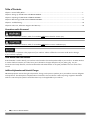
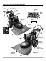
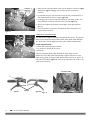
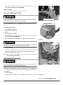
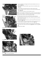
1. Locate the Differential Lock In/Out Cable along the right Handlebar. There
is an In-Line Adjuster to change the length of the Cable (Figure 28).
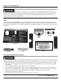
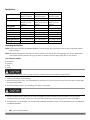
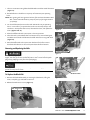
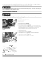
2. With the Lock In/Out Lever in the Out position (lever back), there should be
a slight amount of slack in the Cable exposed at the spring end (Figure 29)
and the Lock In/Out Sleeve should be all the way to the right (toward the
outside).
NOTE: If the cable appears to have plenty of travel and the Sleeve is still not fully to
the outside, you may have to clean and lubricate the Sleeve. See page 16 for
Lubrication.
Figure 28
Lock In/Out Cable Spring
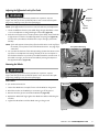
3. You can take the slack out of the cable by holding the Hex Flat Section at the
top of the In-Line Adjuster and rotating the body of the In-Line Adjuster in
the clockwise direction as you look up the Cable toward the Control Panel. If
the Cable is too tight, you can loosen the Cable by twisting the adjuster in
the opposite direction (Figure 28).
Lock
In/Out
Sleeve
Removing the Wheels
Before performing any maintenance procedure or inspection, stop the
engine, wait five (5) minutes to allow all parts to cool. Disconnect the spark
plug wire(s), keeping it away from the spark plug(s).
In
Out
Lock In/Out Sleeve in
the Out position
Figure 29
Tools needed:
• 3/4" Socket with extension
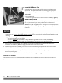
Wheel Nuts
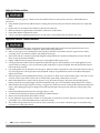
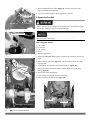
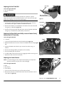
1. Loosen the Wheel Nuts a couple of turns with the Wheel on the ground.
2. Block the machine so the Wheel you are removing is off the ground.
3. Remove the three (3) Nuts and slide the Wheel off (Figure 30).
4. Replace the Wheel and finger-tighten the Wheel Nuts before unblocking the
machine.
5. Tighten the Wheel Nuts with the Wheel resting on the ground.
Figure 30
CONTACT US AT www.DRpower.com
21