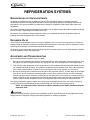
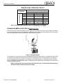
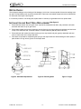
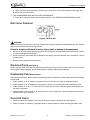
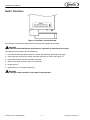
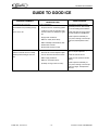
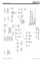
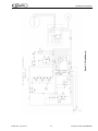
1
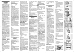
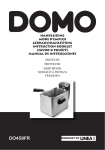
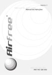
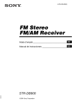
ICE MAKER - WM600 AND CM600
Service Manual
Release Date: March 11, 2004
Publication Number: 630460082SER
Revision Date: March 18, 2014
Revision: C
Visit the Cornelius web site at www.cornelius.com for all your Literature needs.
The products, technical information, and instructions contained in this manual are subject to change without notice.
These instructions are not intended to cover all details or variations of the equipment, nor to provide for every possible contingency in the installation, operation or maintenance of this equipment. This manual assumes that the person(s) working on the equipment have been trained and are skilled in working with electrical, plumbing, pneumatic,
and mechanical equipment. It is assumed that appropriate safety precautions are taken and that all local safety and
construction requirements are being met, in addition to the information contained in this manual.
This Product is warranted only as provided in Cornelius’ Commercial Warrant applicable to this Product and is subject to all of the restrictions and limitations contained in the Commercial Warranty.
Cornelius will not be responsible for any repair, replacement or other service required by or loss or damage resulting
from any of the following occurrences, including but not limited to, (1) other than normal and proper use and normal
service conditions with respect to the Product, (2) improper voltage, (3) inadequate wiring, (4) abuse, (5) accident,
(6) alteration, (7) misuse, (8) neglect, (9) unauthorized repair or the failure to utilize suitably qualified and trained persons to perform service and/or repair of the Product, (10) improper cleaning, (11) failure to follow installation, operating, cleaning or maintenance instructions, (12) use of “non-authorized” parts (i.e., parts that are not 100%
compatible with the Product) which use voids the entire warranty, (13) Product parts in contact with water or the
product dispensed which are adversely impacted by changes in liquid scale or chemical composition.
Contact Information:
To inquire about current revisions of this and other documentation or for assistance with any Cornelius product contact:
www.cornelius-usa.com
800-238-3600
Trademarks and Copyrights:
This document contains proprietary information and it may not be reproduced in any way without permission from
Cornelius.
This document contains the original instructions for the unit described.
CORNELIUS INC
101 Regency Drive
Glendale Heights, IL
Tel: + 1 800-238-3600
Printed in U.S.A.
TABLE OF CONTENTS
Safety Instructions . . . . . . . . . . . . . . . . . . . . . . . . . . . . . . . . . . . . . . . . . . . . . . . . . . . . . . . . . . . . . . . . 1
Read and Follow ALL Safety Instructions . . . . . . . . . . . . . . . . . . . . . . . . . . . . . . . . . . . . . . . . . . . . . 1
Safety Overview . . . . . . . . . . . . . . . . . . . . . . . . . . . . . . . . . . . . . . . . . . . . . . . . . . . . . . . . . . . . . 1
Recognition . . . . . . . . . . . . . . . . . . . . . . . . . . . . . . . . . . . . . . . . . . . . . . . . . . . . . . . . . . . . . . . . . 1
Different Types of Alerts . . . . . . . . . . . . . . . . . . . . . . . . . . . . . . . . . . . . . . . . . . . . . . . . . . . . . . . . . . 1
Safety Tips . . . . . . . . . . . . . . . . . . . . . . . . . . . . . . . . . . . . . . . . . . . . . . . . . . . . . . . . . . . . . . . . . . . . 1
Qualified Service Personnel . . . . . . . . . . . . . . . . . . . . . . . . . . . . . . . . . . . . . . . . . . . . . . . . . . . . . . . 1
Safety Precautions . . . . . . . . . . . . . . . . . . . . . . . . . . . . . . . . . . . . . . . . . . . . . . . . . . . . . . . . . . . . . . 2
Shipping And Storage . . . . . . . . . . . . . . . . . . . . . . . . . . . . . . . . . . . . . . . . . . . . . . . . . . . . . . . . . . . . 2
General Information . . . . . . . . . . . . . . . . . . . . . . . . . . . . . . . . . . . . . . . . . . . . . . . . . . . . . . . . . . . . . . . 3
Specifications . . . . . . . . . . . . . . . . . . . . . . . . . . . . . . . . . . . . . . . . . . . . . . . . . . . . . . . . . . . . . . . . . . 3
Description . . . . . . . . . . . . . . . . . . . . . . . . . . . . . . . . . . . . . . . . . . . . . . . . . . . . . . . . . . . . . . . . . . . . 3
Installation Instructions . . . . . . . . . . . . . . . . . . . . . . . . . . . . . . . . . . . . . . . . . . . . . . . . . . . . . . . . . . . 3
Remove Ice Maker From Carton: . . . . . . . . . . . . . . . . . . . . . . . . . . . . . . . . . . . . . . . . . . . . . . . . . . . 3
Cabinet Removal . . . . . . . . . . . . . . . . . . . . . . . . . . . . . . . . . . . . . . . . . . . . . . . . . . . . . . . . . . . . . . . 3
Preparation of Installation Site . . . . . . . . . . . . . . . . . . . . . . . . . . . . . . . . . . . . . . . . . . . . . . . . . . . . . 3
Water Inlet Hook–up: . . . . . . . . . . . . . . . . . . . . . . . . . . . . . . . . . . . . . . . . . . . . . . . . . . . . . . . . . . . . 4
Electrical Supply . . . . . . . . . . . . . . . . . . . . . . . . . . . . . . . . . . . . . . . . . . . . . . . . . . . . . . . . . . . . . . . . 4
Auger Engagement . . . . . . . . . . . . . . . . . . . . . . . . . . . . . . . . . . . . . . . . . . . . . . . . . . . . . . . . . . . . . . 4
Initial start up, checks and adjustment instructions . . . . . . . . . . . . . . . . . . . . . . . . . . . . . . . . . . . . . . 5
Guide to Service . . . . . . . . . . . . . . . . . . . . . . . . . . . . . . . . . . . . . . . . . . . . . . . . . . . . . . . . . . . . . . . . . . 6
Ice maker cleaning and sanitizing procedures . . . . . . . . . . . . . . . . . . . . . . . . . . . . . . . . . . . . . . . . . 6
Maintenance . . . . . . . . . . . . . . . . . . . . . . . . . . . . . . . . . . . . . . . . . . . . . . . . . . . . . . . . . . . . . . . . . . . 6
Monthly . . . . . . . . . . . . . . . . . . . . . . . . . . . . . . . . . . . . . . . . . . . . . . . . . . . . . . . . . . . . . . . . . . . . 6
Quarterly . . . . . . . . . . . . . . . . . . . . . . . . . . . . . . . . . . . . . . . . . . . . . . . . . . . . . . . . . . . . . . . . . . . 6
Semi-Annually . . . . . . . . . . . . . . . . . . . . . . . . . . . . . . . . . . . . . . . . . . . . . . . . . . . . . . . . . . . . . . . 7
Water Level Control . . . . . . . . . . . . . . . . . . . . . . . . . . . . . . . . . . . . . . . . . . . . . . . . . . . . . . . . . . . . . . . 8
Water Level Control Operation . . . . . . . . . . . . . . . . . . . . . . . . . . . . . . . . . . . . . . . . . . . . . . . . . . . . . 8
Purpose of Water Level Control . . . . . . . . . . . . . . . . . . . . . . . . . . . . . . . . . . . . . . . . . . . . . . . . . . . . 8
To Replace Water Level Control . . . . . . . . . . . . . . . . . . . . . . . . . . . . . . . . . . . . . . . . . . . . . . . . . . . . 8
To Replace Water Level Safety Switch . . . . . . . . . . . . . . . . . . . . . . . . . . . . . . . . . . . . . . . . . . . . . . . 9
Ice Level Control . . . . . . . . . . . . . . . . . . . . . . . . . . . . . . . . . . . . . . . . . . . . . . . . . . . . . . . . . . . . . . . . 9
Refrigeration Systems . . . . . . . . . . . . . . . . . . . . . . . . . . . . . . . . . . . . . . . . . . . . . . . . . . . . . . . . . . . . 10
Refrigeration system adjustments . . . . . . . . . . . . . . . . . . . . . . . . . . . . . . . . . . . . . . . . . . . . . . . . . . 10
Expansion Valve . . . . . . . . . . . . . . . . . . . . . . . . . . . . . . . . . . . . . . . . . . . . . . . . . . . . . . . . . . . . . . . 10
Adjustment and Troubleshooting . . . . . . . . . . . . . . . . . . . . . . . . . . . . . . . . . . . . . . . . . . . . . . . . . . 10
Temperature / Pressure Chart* . . . . . . . . . . . . . . . . . . . . . . . . . . . . . . . . . . . . . . . . . . . . . . . . . . . . 11
Condenser Modulating Valve . . . . . . . . . . . . . . . . . . . . . . . . . . . . . . . . . . . . . . . . . . . . . . . . . . . . . 11
Condenser Modulating Valve Removal . . . . . . . . . . . . . . . . . . . . . . . . . . . . . . . . . . . . . . . . . . . . . . 12
Gear Motor . . . . . . . . . . . . . . . . . . . . . . . . . . . . . . . . . . . . . . . . . . . . . . . . . . . . . . . . . . . . . . . . . . . 12
Troubleshooting . . . . . . . . . . . . . . . . . . . . . . . . . . . . . . . . . . . . . . . . . . . . . . . . . . . . . . . . . . . . . . . . . 13
Troubleshooting Gear Motors . . . . . . . . . . . . . . . . . . . . . . . . . . . . . . . . . . . . . . . . . . . . . . . . . . . . . 13
The Gearmotor Will Not Run . . . . . . . . . . . . . . . . . . . . . . . . . . . . . . . . . . . . . . . . . . . . . . . . . . . 13
The Gearmotor Starts but Trips Repeatedly On The Overload Protector . . . . . . . . . . . . . . . . . 13
The Motor Runs but Output Shaft Does not Rotate . . . . . . . . . . . . . . . . . . . . . . . . . . . . . . . . . 13
Overload Check: . . . . . . . . . . . . . . . . . . . . . . . . . . . . . . . . . . . . . . . . . . . . . . . . . . . . . . . . . . . . . . . 13
Motor Check: . . . . . . . . . . . . . . . . . . . . . . . . . . . . . . . . . . . . . . . . . . . . . . . . . . . . . . . . . . . . . . . . . . 14
Installation and Shaft Seal Replacement . . . . . . . . . . . . . . . . . . . . . . . . . . . . . . . . . . . . . . . . . . . . 14
Auger & Extruding Head Removal . . . . . . . . . . . . . . . . . . . . . . . . . . . . . . . . . . . . . . . . . . . . . . . . . 15
To Replace Bearings . . . . . . . . . . . . . . . . . . . . . . . . . . . . . . . . . . . . . . . . . . . . . . . . . . . . . . . . . . . 15
Troubleshooting Compressor . . . . . . . . . . . . . . . . . . . . . . . . . . . . . . . . . . . . . . . . . . . . . . . . . . . . . 15
Electrical Checkout . . . . . . . . . . . . . . . . . . . . . . . . . . . . . . . . . . . . . . . . . . . . . . . . . . . . . . . . . . . . . 16
Overload Check . . . . . . . . . . . . . . . . . . . . . . . . . . . . . . . . . . . . . . . . . . . . . . . . . . . . . . . . . . . . . . . 16
Compressor Check . . . . . . . . . . . . . . . . . . . . . . . . . . . . . . . . . . . . . . . . . . . . . . . . . . . . . . . . . . . . . 16
Capacitor Check . . . . . . . . . . . . . . . . . . . . . . . . . . . . . . . . . . . . . . . . . . . . . . . . . . . . . . . . . . . . . . . 16
Safety Controls . . . . . . . . . . . . . . . . . . . . . . . . . . . . . . . . . . . . . . . . . . . . . . . . . . . . . . . . . . . . . . . . 17
Guide to Good Ice . . . . . . . . . . . . . . . . . . . . . . . . . . . . . . . . . . . . . . . . . . . . . . . . . . . . . . . . . . . . . . . . 18
Ice Maker Service Manual
SAFETY INSTRUCTIONS
READ AND FOLLOW ALL SAFETY INSTRUCTIONS
Safety Overview
•
Read and follow ALL SAFETY INSTRUCTIONS in this manual and any warning/caution labels on the unit (decals, labels or
laminated cards).
•
Read and understand ALL applicable OSHA (Occupational Safety and Health Administration) safety regulations before
operating this unit.
Recognition
Recognize Safety Alerts
!
This is the safety alert symbol. When you see it in this manual or on the unit,
be alert to the potential of personal injury or damage to the unit.
DIFFERENT TYPES OF ALERTS
! DANGER:
Indicates an immediate hazardous situation which if not avoided WILL result in serious injury, death or equipment
damage.
! WARNING:
Indicates a potentially hazardous situation which, if not avoided, COULD result in serious injury, death, or equipment
damage.
! CAUTION:
Indicates a potentially hazardous situation which, if not avoided, MAY result in minor or moderate injury or equipment
damage.
SAFETY TIPS
•
Carefully read and follow all safety messages in this manual and safety signs on the unit.
•
Keep safety signs in good condition and replace missing or damaged items.
•
Learn how to operate the unit and how to use the controls properly.
•
Do not let anyone operate the unit without proper training. This appliance is not intended for use by very young children or
infirm persons without supervision. Young children should be supervised to ensure that they do not play with the appliance.
•
Keep your unit in proper working condition and do not allow unauthorized modifications to the unit.
QUALIFIED SERVICE PERSONNEL
! WARNING:
Only trained and certified electrical, plumbing and refrigeration technicians should service this unit. ALL WIRING
AND PLUMBING MUST CONFORM TO NATIONAL AND LOCAL CODES. FAILURE TO COMPLY COULD
RESULT IN SERIOUS INJURY, DEATH OR EQUIPMENT DAMAGE.
Publication Number: 630460082SER
-1-
© 2004-2014, Cornelius Inc.
Ice Maker Service Manual
SAFETY PRECAUTIONS
This unit has been specifically designed to provide protection against personal injury. To ensure continued protection
observe the following:
! WARNING:
Disconnect power to the unit before servicing following all lock out/tag out procedures established by the user. Verify
all of the power is off to the unit before any work is performed.
Failure to disconnect the power could result in serious injury, death or equipment damage.
! CAUTION:
Always be sure to keep area around the unit clean and free of clutter. Failure to keep this area clean may result in
injury or equipment damage.
SHIPPING AND STORAGE
! CAUTION:
Before shipping, storing, or relocating the unit, the unit must be sanitized and all sanitizing solution must be drained
from the system. A freezing ambient environment will cause residual sanitizing solution or water remaining inside the
unit to freeze resulting in damage to internal components.
! CAUTION:
Very high discharges pressure is present in system. Quick disconnects on your gages will minimize danger and loss
of refrigerant.
! CAUTION:
Unit requires separate electrical line. See instruction manual for proper fuse size.
! WARNING:
There must be adequate clearance around ice maker. Allow minimum 6” air intake and 4” air exhaust for air
exhaust and panel removal.
NOTE: Unit must be installed per local plumbing and electrical codes. See Installation manual for
unit requirements. Failure to do so may cause damage to unit, which would void unit warranty.
NOTE: Using any parts other than genuine factory manufactured parts relieves the manufacturer
of all liability.
NOTE: Manufacturer reserves the right to change specifications at any time.
© 2004-2014, Cornelius Inc.
-2-
Publication Number: 630460082SER
Ice Maker Service Manual
GENERAL INFORMATION
SPECIFICATIONS
Model WM (Wall Model) 600 and CM (Counter Model) 600
Compressor
3/4 H.P. (R404 Refrigerant)
Voltage
115 VAC, 60 Hz, Single Phase
Current Draw
16 Amps
Circuit Breaker or Fuse Size
20 Amp Maximum Time Delay
DESCRIPTION
Models WM600 and CM600 Ice Makers are self-contained wall mount and counter style Units which automatically
make hard compressed-style ice and store it in a sealed hopper for sanitary dispensing.
INSTALLATION INSTRUCTIONS
IMPORTANT: An Ever pure Model 9320 – 42 Systems IV Model DB900 ice maker quality water
treatment unit MUST BE INSTALLED in the water supply line to the Ice Maker. Failure to do so may
result in poor quality ice, low production output, and may cause premature failure of the Ice Maker
evaporator and void the extended evaporator warranty.
This Ice Maker is provided with a stainless–steel evaporator designed to last the life of the product. But,
some of the chemicals in treated and untreated water, specifically chlorine and sulphur (sulphide), have the
ability to attack stainless–steel and cause premature failure. An initial investment in proper water treatment
will pay for itself in increased production, quality, and long life of the product.
REMOVE ICE MAKER FROM CARTON:
1. Keep Unit in the upright position, remove carton and pallet from the Unit and inspect the unit for damage. Upon
inspection of the unit, if any damage is found, file a claim with the carrier immediately.
2. Locate the Startup Card either on the outside of the container or on the plastic liner. Fill in the proper information and send one copy to the factory and the other copy to the Distributor. The postage is prepaid.
CABINET REMOVAL
1. Unscrew and remove the front panels for electrical and start–up access.
2. Remove shipping tape from the storage hopper cover and the agitator in storage hopper.
PREPARATION OF INSTALLATION SITE
1. For maximum efficiency and ice output, select a location for your ice maker where it will not be exposed to sunlight, excessive heat or reflected radiation (preferably in a room with a temperature of 70° F to 80° F). The icemaker normally will not function properly in temperatures below 65° F. The area surrounding the ice maker
should be well ventilated. (Consult ???? for proper airflow clearance). WM600 – Two (2) mounting brackets are
supplied for securing the Unit to a wall.
CM600 – Consult Figure 1B and 1C for dimensions for mounting the Unit to the counter. Note that the Unit must be
level for proper operation.
2. The Unit must be sealed to the counter. Locate the desired position for the Unit, then mark the outline dimensions on the counter.
Publication Number: 630460082SER
-3-
© 2004-2014, Cornelius Inc.
Ice Maker Service Manual
3. Apply a continuous bead of NSF listed silastic sealant (Dow 732 or equal) approximately 1/4–inch inside of the
Unit outline dimensions. Then, position the Unit on the counter within the outline dimensions. All excess sealant must be wiped away immediately.
IMPORTANT: The WM600 with a full ice storage hopper weighs 450 pounds. Make sure that the
mounting surface is adequately reinforced to support this weight.
The mounting hole dimensions for the brackets are shown in Figure 1 Use these dimensions to locate the Unit at the
desired height on the wall.
IMPORTANT: Provide support for the Unit until all eight (8)–mounting bolts are installed. Do not hang
the Unit from the top mounting angle bracket only while installing the lower angle.
WATER INLET HOOK–UP:
1. Water Inlet – The fitting is a 1/4”–in. compression fitting located at the bottom of the Unit. Connect water supply with a 1/4–inch or larger copper or flexible tubing.
2. Water Pressure – Unless otherwise specified, the Unit is designed to operate on a water pressures between
10 P.S.I. and 90 P.S.I. (NOTE: for pressures above 90 P.S.I; a water pressure regulator must be installed).
3. Water Cooled Condensers – The inlet uses a 3/8–inch compression fitting. Use a separate 3/8–inch or larger
water line.
4. Filters – Filter Conditioners are recommended on supply lines to the Ice Makers. Never run the water supply to
the water cooled condenser through a Filter/Conditioner. It uses up the cartridge unnecessarily and a saturated
cartridge can starve the Ice Maker causing premature component damage. Separate water supplies are recommended.
WM600 – Connect a 1–1/4 inch IPS (or equal) drain line to the 1–1/4 inch diameter P–trap at the lower bottom of
the Unit. The line must pitch downward to an open drain and must contain no traps or improper drainage will
result.
CM600 – Connect two (2) 3/4–inch IPS (or equal) drain lines to the 3/4–inch threaded drain connections at the
lower rear of the Unit. These lines must pitch downward to an open drain and must contain no traps or improper
drainage will result. For water–cooled Units, a third 3/4–inch FPT drain fitting is provided for the condenser drain
(see Figure 1B).
NOTE: The Unit must be installed per local plumbing codes.
ELECTRICAL SUPPLY
1. Power Access – Is provided by way of a 7/8–inch diameter hole located on the lower left side of the Unit.
Route incoming power in conduit, to the Ice Maker electrical control box. Make connections to wires provided in
the control box and the ground lug/screw.
2. Fused Line – Should be a dedicated circuit checked and sized according to the electrical rating shown on the
Unit nameplate.
NOTE: The Unit must be installed per local electrical codes.
AUGER ENGAGEMENT
Be certain that the auger is fully engaged to the lower drive and that the extruding head is fully engaged to the
evaporator.
© 2004-2014, Cornelius Inc.
-4-
Publication Number: 630460082SER
Ice Maker Service Manual
INITIAL START UP, CHECKS AND ADJUSTMENT INSTRUCTIONS
NOTE: Do not start the Unit before completing the previous Installation steps.
Turn on the water supply and main power switch (located on top of the electrical box).
NOTE: If the Unit will not start, be sure the water reservoir is full. The low water safety control must
be properly adjusted to start and shut down the Unit. If the water level drops below the bottom of
the reservoir, the Unit must shut down. Adjustment is made by moving the magnet up or down.
Figure 1. Float Adjustment
Water Level Control Adjustment – If necessary, adjust the float by bending the float arm up or down as
needed. Push the float assembly down until the Unit stops running. Release the float and the Unit will
restart. Keep water in the reservoir at the level line while the Unit is in operation (See Figure 1).
Low Water Safety Control – Adjust the magnet by bending the magnet arm as shown in Figure 1 to shut down the
Unit if the water level drops below the line on the side of the reservoir.
Bin Control – Remove four clips from top of the bin cover and lift cover so the bin control switch can be manually lifted
until the Unit shuts down. Release the plate and unit will restart
Dispense Switch and Mechanism – By depressing the dispense switch, the dispense mechanism door on the
storage bin will open, and the agitator will rotate counterclockwise.
NOTE: If any of these checks or adjustments cannot be achieved, refer to Troubleshooting Section
of this manual or call our Technical Support Center for assistance.
Publication Number: 630460082SER
-5-
© 2004-2014, Cornelius Inc.
Ice Maker Service Manual
GUIDE TO SERVICE
IMPORTANT: Preventive maintenance can increase the trouble-free life of your Ice Maker. Failure to
perform preventive maintenance could void your equipment warranty.
ICE MAKER CLEANING AND SANITIZING PROCEDURES
IMPORTANT: Do not use any of the ice made during cleaning operations.
Clean and sanitize ice storage area when cleaning Ice Maker.
! WARNING:
Disconnect power to the unit before servicing. Follow all lock out/tag out procedures established by the user. Verify all
power is off to the unit before performing any work.
Failure to comply could result in serious injury, death or damage to the equipment.
1. Turn Ice Maker off.
2. Shut off water supply.
3. Remove ice from storage bin.
4. Mix approved cleaner (2 gallons as directed). Recommended cleaner: Calgon Corp. or Virginia Chemicals, ice
machine cleaner. Mixture: 3–1/3 ounces per gallon water. Do not use nickel safe cleaners.
5. Turn Ice Maker on and add cleaner solution to water level control (float reservoir) until 2 gallons have been
used.
6. Turn on water supply and operate Ice Maker for 15 minutes.
7. Turn Ice Maker off. Remove and discard all ice.
8. Sanitize using household liquid bleach (50 ppm chlorine). Mixture: 1 fluid ounce per gallon room temperature
water. Allow a two minute exposure time.
9. Sanitize pre–cleaned inside areas of storage bin liner, door frame, door, as well as all exposed surfaces of the
evaporator assembly and the bin shutoff assembly with sanitizing solution. Allow to air dry.
MAINTENANCE
Preventative Maintenance can increase the trouble-free life of your Ice Maker. Many Authorized Cornelius Service
Agencies offer service contracts. Contact your local distributor for further information.
Monthly
1. Clean the condenser coil. Use a brush, vacuum cleaner, or blow from inside the coil with air or CO2 gas.
2. Inspect the water feed reservoir at least once a month until a definite pattern for cleaning and sanitizing has
been established.
Quarterly
This is the maximum period of time between cleaning and sanitizing the Ice Maker. In addition to recommended
monthly procedure, and if a more frequent cleaning and sanitizing pattern has not been established, the Ice Maker
must be cleaned and sanitized quarterly.
© 2004-2014, Cornelius Inc.
-6-
Publication Number: 630460082SER
Ice Maker Service Manual
Semi-Annually
Semi-annually, in addition to all previously established service procedures, perform the following:
1. Check for water leaks; tube connections, water fittings, and the lower icemaker water seal.
2. Check the drain tubes for clogs and ”aged” tubes. Replace if tubes are stained or brittle.
Figure 2. Auger Assembly
3. Check for signs of condensation. Clean where necessary and replace insulation properly.
4. Check safety circuits for proper operation.
5. Check refrigeration system (see REFRIGERATION SYSTEMS section of this manual).
6. Check Unit for abnormal noise. Tighten machine and cabinet screws, if necessary.
7. Check white upper bearings on auger assembly (see Figure 2). If bearing are less than 1/16-inch thick, replace
the bearings.
Publication Number: 630460082SER
-7-
© 2004-2014, Cornelius Inc.
Ice Maker Service Manual
WATER LEVEL CONTROL
WATER LEVEL CONTROL OPERATION
When water is introduced through the inlet fitting, the float rises (see Figure 1). The float pushes against a lever that in
turn, forces the poppet assembly against the inlet fitting valve seat that seals the water off. Before the water inlet is
sealed, the safety switch is operated. In the event of a water failure, the float would drop down and operate the safety
switch to shut off the Unit.
If water level control will not shut off and seal at level as indicated, be sure inlet pressure does not exceed
recommended factory operating range.
Under ordinary circumstances, the water level control adjustment should not be necessary providing the control was
properly adjusted when the Unit was installed or relocated (see “Water Level Control Adjustment ” in “INSTALLATION
INSTRUCTIONS” SECTION of this manual). If however, the water level control becomes inoperative, repair or replace
the control.
PURPOSE OF WATER LEVEL CONTROL
1. To automatically maintain the proper water level in the evaporator when the Unit is operating and making ice.
2. A safety switch is operated in the event of an interruption in the water supply. The switch shuts off the electrical
power to the Ice Maker and it’s refrigeration system. The switch will reset as soon as the cause of the water failure has been corrected and the proper water level in the Ice Maker has again been reached.
3. The transparent bowl not only provides a visible check of the water level, but also is a good guide to the internal
conditions which exist within the Ice Maker assembly itself (see cleaning procedure).
TO REPLACE WATER LEVEL CONTROL
! WARNING:
Disconnect power to the unit before servicing. Follow all lock out/tag out procedures established by the user. Verify all
power is off to the unit before performing any work.
Failure to comply could result in serious injury, death or damage to the equipment.
1. Shut off the water supply. Shut off the main power switch or unplug the Ice Maker from electrical outlet.
2. Remove flexible tubing from bottom of the water level control, then drain water from the water level control and
evaporator.
3. Remove flexible tubing at bottom of the water level bowl connected to the overflow.
4. Hold water inlet fitting with proper tool to prevent it from rotating when disconnecting the water inlet.
5. Remove wing nut holding the water control to its mounting bracket. The control can be removed by lifting it
straight up.
© 2004-2014, Cornelius Inc.
-8-
Publication Number: 630460082SER
Ice Maker Service Manual
TO REPLACE WATER LEVEL SAFETY SWITCH
! WARNING:
Disconnect power to the unit before servicing. Follow all lock out/tag out procedures established by the user. Verify all
power is off to the unit before performing any work.
Failure to comply could result in serious injury, death or damage to the equipment.
1. Shut off main power switch or unplug the Ice Maker from electrical outlet.
2. Unplug Molex connector connecting switch to the electrical box.
3. Remove two screws anchoring the water level safety switch to the bottom of the water level control mounting
bracket.
ICE LEVEL CONTROL
The ice level control assembly is secured to the top of the ice storage container cover. When the switch assembly is
down, due to lack of ice in the ice storage container, an electrical impulse is sent to the compressor to start the ice
making cycle. As ice level increases in the ice storage container, the switch assembly is pushed back. When the ice
storage container is full, it de-actuates the switch which stops the compressor and the ice making cycle.
Publication Number: 630460082SER
-9-
© 2004-2014, Cornelius Inc.
Ice Maker Service Manual
REFRIGERATION SYSTEMS
REFRIGERATION SYSTEM ADJUSTMENTS
A complete understanding of the Ice Maker and the hermetic refrigeration system is necessary before any
adjustments are made. The refrigeration technician must use high and low side pressure readings, water and air
temperatures, plus general conditions of cleanliness to assess the refrigeration system status when making any
adjustments.
All Ice Maker products are tested and adjusted at the factory prior to shipment where the ambient temperature ranges
from 65° F to 90° F, depending on the season of the year.
Whenever a new Ice Maker is initially installed and started, it is imperative that the start-up operator make the
following checks and readjustments for local conditions.
EXPANSION VALVE
You will find a thermal expansion valve on Cornelius Ice Makers, which is used to control the amount of refrigerant
flowing through the evaporator. Improperly installed or defective expansion valves may cause low production, soft ice,
squeaking from evaporator, and excessive load inside the evaporator.
By using the general refrigeration trouble shooting along with the pressure charts, you can easily determine whether
or not the expansion valve is working properly.
ADJUSTMENT AND TROUBLESHOOTING
When troubleshooting the expansion valve, you must:
1. Be sure you have adequate water flowing into the evaporator, a clean and properly ventilated condenser, and
the system is properly charged and free of any restrictions. Also be sure compressor is operating properly.
2. Take reservoir water temperature and air temperature from the condenser inlet and determine at what pressure
the Ice Maker should be operating. On Ice Makers equipped with a thermostatic valve, there is NO adjustment.
If the correct pressure cannot be obtained, be sure the system has time to stabilize (10–15 minutes).
3. Be sure the sensing bulb is located at the outlet side of the evaporator (about 3–4 inches away from the evaporator) and be sure to insulate well and clamp tightly to tubing. If the system pressures are still not adequate,
take second water and air temperature reading and go over other parts of the system for possible problems. If
proper refrigerant charge is questionable, evacuate the refrigeration system and recharge to nameplate specifications. Leak check the refrigeration system. If the expansion valve still malfunctions replace the valve.
Use general refrigeration system practices when replacing and recharging the unit. After new valve is in place, go
through previous monitored adjustments and troubleshooting to be sure valve is functioning properly.
NOTE: On water-cooled Units, adjust the condenser modulating valve before troubleshooting the
expansion valve.
! CAUTION:
Very high discharge pressure is present in the refrigeration system. Quick disconnects on your gages will minimize
Danger and loss of refrigerant. Comply with federal regulations for reclaiming refrigerant.
© 2004-2014, Cornelius Inc.
- 10 -
Publication Number: 630460082SER
Ice Maker Service Manual
TEMPERATURE / PRESSURE CHART*
± 10 lb Discharge Pressure
Air Tempeature(°F)
REFRIGERANT
TYPE R404A
Water Temperature(°F)
40
65
90
50
174
177
180
60
202
205
208
70
230
233
236
80
265
269
272
90
300
304
307
100
328
334
340
NOTE: *The thermostatic expansion valve is non-adjustable on all models
CONDENSER MODULATING VALVE (Water Cooled Only)
The reason for using a water modulating valve is to supply the correct amount of water to the condenser to maintain
the proper operating pressure in the refrigeration system high side. The flow of water through the valve is increased
as the high side pressure rises and decreases as high side pressure lowers.
Figure 3. Adjustment Screw
To calibrate the amount of water flow with the refrigeration system high side pressure, turn adjustment screw located
on end of the valve opposite the bellows (see Figure 3). Turn adjustment screw counterclockwise to raise opening
point. Opening point of valve should be set to maintain proper operating pressure in refrigeration system high side.
Refer to TEMPERATURE/PRESSURE CHART. Closing point of valve should be set low enough to close valve during
compressor stand by periods.
NOTE: Cold water will absorb more heat faster than warm water. The water flow will therefore automatically increase as inlet temperature increases.
Publication Number: 630460082SER
- 11 -
© 2004-2014, Cornelius Inc.
Ice Maker Service Manual
CONDENSER MODULATING VALVE REMOVAL
! WARNING:
Disconnect power to the unit before servicing. Follow all lock out/tag out procedures established by the user. Verify all
power is off to the unit before performing any work.
Failure to comply could result in serious injury, death or damage to the equipment.
1. Shut off water supply to condenser, then reclaim refrigerant from system.
2. Remove inlet water line from Condenser modulating Valve. Also remove tube from refrigerant high side line.
3. Remove Condenser Modulating Valve and bracket from unit.
4. Remove valve from bracket.
5. Replace Condenser Modulating Valve by reversing Steps 2 thru 4, then pull system into vacuum.
6. Recharge unit with refrigerant per nameplate.
7. Turn power and water on to the unit.
8. With unit operating, adjust modulating valve to proper setting.
9. Go through a complete system check.
GEAR MOTOR
The gear motor is equipped with a start relay and a manual reset overload. When current is applied, the relay
energizes and completes the circuit to the start winding. The motor reaches a predetermined speed and the relay
drops out, disconnecting the start winding. The run winding remains in the circuit as long as current is applied.
The purpose of the overload is to automatically shut off the motor in the event of a mechanical bind of the
transmission, an overload condition within the evaporator, or an electrical malfunction. It does this by sensing
amperage draw. If the motor stalls the start relay would energize and stay energized. The amperage would surge to 5
to 6 times greater than normal draw. In this event, the overload would shut off the transmission in 4 to 8 seconds.
If the motor is subjected to an abnormal load, but does not reach stall condition, the overload will react, but over a
greater period of time. The reaction time depends upon the amperage to which it is subjected.
The overload, through the safety circuit, also shuts off the compressor.
Refer to Troubleshooting Guide.
© 2004-2014, Cornelius Inc.
- 12 -
Publication Number: 630460082SER
Ice Maker Service Manual
TROUBLESHOOTING
IMPORTANT: Only qualified personnel should service internal components or electrical wiring.
TROUBLESHOOTING GEAR MOTORS
Basically, Gear motor problems can be narrowed down to three areas of checkout.
The Gearmotor Will Not Run
1. No voltage to the transmission terminals – check external circuit.
2. Low voltage – check voltage supply.
3. Problems in the gear motor electrical circuit. See Figure 4.
The Gearmotor Starts but Trips Repeatedly On The Overload Protector
1. Voltage – high or low voltage can cause the overload to trip.
2. High Gear motor amperage draw, see Specification Chart for ratings and Troubleshooting Guide.
Figure 4. Output Shaft
The Motor Runs but Output Shaft Does not Rotate
Replace defective gear motor.
! WARNING:
Be sure unit is disconnected from the power source. Disconnect the transmission cable.
OVERLOAD CHECK:
1. Allow motor to cool and reset overload if necessary.
2. Remove motor end bell and stator, if necessary.
3. Check terminals 1 and 3 on overload. No continuity replace overload. Use a volt–ohm meter. See Figure 4 and
Figure 5.
Publication Number: 630460082SER
- 13 -
© 2004-2014, Cornelius Inc.
Ice Maker Service Manual
MOTOR CHECK:
The resistance readings on the windings will be between 5 to 25 ohms. A meter capable of these low readings must
be used. The Start Relay cover must be removed. NOTE: Gear motor and related components can be checked from
Pin Connector. See Figure 5 and Figure 6.
If no continuity on start or run winding test, replace stator. If continuity on grounded motor test, replace stator.
INSTALLATION AND SHAFT SEAL REPLACEMENT (See Figure 5)
1. Place shaft seal locator seat over gear motor output shaft, embossed side down, and push down until shaft
seal seat rests flush on top of gear motor.
2. Place rubber coated ceramic seal (important: ceramic face up) over output shaft and push down until seal rests
on top of the shaft seal seat. (Lubricate rubber on ceramic seal with [#06195] rubber lubricant.)
3. Place shaft seal with carbon face down (spring up) over output shaft and push (gently) downward until seal
rests on carbon face of the output shaft seal.
4. Push down on the washer compressing the spring on the output shaft seal. While holding the seals (down) in
place slide the E–ring into the groove on the output shaft.
Figure 5. Shaft Seal Replacement
© 2004-2014, Cornelius Inc.
Figure 6. Extruding Head
- 14 -
Figure 7. Auger
Publication Number: 630460082SER
Ice Maker Service Manual
AUGER & EXTRUDING HEAD REMOVAL
Figure 8. Upper Nut and Bearing
The upper bearings located on top of the auger is used to absorb the force between the auger and extruding head.
The bearings are 3/32” thick. When they wear below 1/16” they should be replaced. Bearings to be inspected
for wear during quarterly maintenance. See Figure 8.
TO REPLACE BEARINGS
! WARNING:
Disconnect power to the unit before servicing. Follow all lock out/tag out procedures established by the user. Verify all
power is off to the unit before performing any work.
Failure to comply could result in serious injury, death or damage to the equipment.
1. Dispense all ice from unit.
2. Remove panels.
3. Unplug Dispense Motor and Ice Level Switch.
4. Remove four screws holding dispense cover in place.
5. Remove dispense cover assembly.
6. Use an open end wrench on auger nut connected to bearing and turn counterclockwise to remove assembly.
7. Remove worn bearings. Replace with new bearings and then reinstall assembly.
NOTE: If auger turns with nut, remove cover on top of gear motor stator and hold rotor while loosening nut.
8. Reconnect power to icemaker.
TROUBLESHOOTING COMPRESSOR
Basically the compressor problems can be narrowed down to three areas of checkout–
1. THE COMPRESSOR WILL NOT RUN
A. No voltage to the compressor terminals – check circuit.
B. Low voltage – below 90% of nameplate rated voltage.
C. Problems in the compressor electrical circuit. See Electrical Checkout instructions.
2. THE COMPRESSOR STARTS BUT TRIPS REPEATEDLY ON THE OVERLOAD PROTECTOR
A. Check for proper fan operation and clean condenser.
B. Check the compressor suction and discharge pressures.
C. Voltage – The voltage should be within 10% of the rated nameplate voltage.
Publication Number: 630460082SER
- 15 -
© 2004-2014, Cornelius Inc.
Ice Maker Service Manual
D. High compressor amperage draw, it should never exceed 120% of the rated nameplate amperage. See
Electrical Checkout Instructions.
3. THE COMPRESSOR RUNS BUT WILL NOT REFRIGERATE
A. Check the compressor suction and discharge pressures. See TEMPERATURE/PRESSURE CHART.
ELECTRICAL CHECKOUT
Figure 9. Electrical Box
! WARNING:
Disconnect power to the unit before servicing. Follow all lock out/tag out procedures established by the user. Verify all
power is off to the unit before performing any work.
Failure to comply could result in serious injury, death or damage to the equipment.
1. Be sure the unit is disconnected from the power source. Remove the compressor electrical box cover. Check
for obvious damage and loose wires.
2. Disconnect the fan motor leads. Since capacitors store energy, short the capacitor with a screwdriver. This will
prevent shocks.
3. Disconnect the compressor terminal wires.
OVERLOAD CHECK (See Figure 4)
Using a volt–ohm meter check the continuity across the overload, contacts #1 & #3. If none, wait for unit to cool down
and try again. If still no continuity, the overload protector is defective and should be replaced.
COMPRESSOR CHECK (See Figure 9)
The resistance readings on the windings will be between 0.25 and 10.00 ohms, a meter capable of these low readings
must be used.
1. Check between “C” & “R.” Replace compressor if there is no continuity as the run windings are open.
2. Check between “C” & “S.” Replace the compressor if there is no continuity as the start windings are open.
3. Check between “C” & “R”, or “S” and shell of the compressor. If there is continuity replace the compressor as
the motor is grounded.
4. Check between screw terminal on the overload and “C” on the compressor. Check and repair the lead or connections if there is no continuity.
CAPACITOR CHECK
1. Check or replace start capacitor, disconnect bleed resistor before checking for shorted capacitor.
2. Check or replace run capacitor (if supplied) check or shorted capacitor or either terminal grounded to case.
© 2004-2014, Cornelius Inc.
- 16 -
Publication Number: 630460082SER
Ice Maker Service Manual
SAFETY CONTROLS
Figure 10. Gear Motor Thermal Overload
Your Icemaker unit has several safety and control devices incorporated into its design.
! WARNING:
None of the below described devices should ever be ”bypassed” to allow the unit to function.
The safety and control system shut–off devices are:
1. Low water shut off reed switch located in icemaker float assembly. (Automatic reset type).
2. Gear motor thermal overload, manual reset type (red button on motor). See Figure 10.
3. Compressor thermal overload, automatic reset type.
4. Main service switch located on top of the control box.
5. Hopper shut–off.
6. High pressure cut out (water cooled only).
! WARNING:
Do not reset gear motor overload if ice is present in the evaporator.
Publication Number: 630460082SER
- 17 -
© 2004-2014, Cornelius Inc.
Ice Maker Service Manual
GUIDE TO GOOD ICE
CUSTOMER COMMENTS
It runs but the ice is too soft.
The icemaker is not producing enough
ice.
The ice is too wet.
CHECK ICEMAKER LOCATION
CONDITIONS FIRST
Under compression
Proper air flow for condensing system
Location too close to high temp units
such as coffee urns, deepfryers, grills
etc.
Supply water conditions.
Water too warm (above 90°F)
Water artificially softened above 262
PPM sodium chloride.
CHECK ICEMAKER
Use gages for checking suction
and head pressures. See manual
for correct reading and conditions.
Check water level for proper adjustent and restrictions. See Manual.
Check evaporator assembly for
worn parts, bearings, scored evaporator and, bad expansion valve,
etc.
Normal water supply too high.
It makes too much noise.
(with this comment the ice is usually
extremely hard and larger thant normal).
Over Compression
Check to see if noise objection objections is normal fan and air flow noise.
Water supply conditions.
Water too cold (below 50°F)
(Possibly running from Pre-cooler).
© 2004-2014, Cornelius Inc.
- 18 -
Obstructions partially blocking ice
exit from top of evaporator.
Check fan and fan shroud.
Check for loose parts and screws
rattling.
Check evaporator assembly for
worn parts, bearings, scored evaporator and auger, bad expansion
valve etc.
Publication Number: 630460082SER
Figure 11. Troubleshooting Chart
Ice Maker Service Manual
Publication Number: 630460082SER
- 19 -
© 2004-2014, Cornelius Inc.
Figure 12. Wiring Diagram
Ice Maker Service Manual
© 2004-2014, Cornelius Inc.
- 20 -
Publication Number: 630460082SER
Ice Maker Service Manual
Figure 13. Mounting Template
Publication Number: 630460082SER
- 21 -
© 2004-2014, Cornelius Inc.
Ice Maker Service Manual
© 2004-2014, Cornelius Inc.
- 22 -
Publication Number: 630460082SER
Cornelius Inc.
www.cornelius.com