1
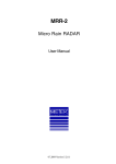
range hood
Model#: 03012S-HHSS / 03012K-HHSS / 03012K3-HHSS
Installation
Guide and
User Manual
Please read and save this guide through before using your
chimney hood. Store the guide away in a safe place so that
you will know where it is, when you want to refer to it.
Table of Contents
A. Important Safety Instructions .................................................... -Installation . ............................................................................ -Operations ............................................................................. -Cleaning ................................................................................ 03
03
04
05
B. Before You Start ..................................................................... 06
C. Electrical Requirements ............................................................ 10
D. List of Materials ........................................................................ 12
E. Planning for the Installation .................................................... -Dimensions ............................................................................ -Important ............................................................................... -Venting Method . .................................................................... 14
14
14
16
F. Installation Instructions ............................................................. 19
G. Maintenance . ........................................................................... 22
H. Trouble Shooting ...................................................................... 24
I. Range hood operations ............................................................ 26
J. Wiring Diagram ...................................................................... 26
K. Specification . ........................................................................... 27
• Read and save these instructions save this guide for local electrical
inspector’s use .
• Approved for residential appliances
• For residential use only
Installation must comply with all local codes.
• Requirement: 120V AC, 60Hz. 15 or 20 A Branch Circuit
• Must read the entire instructions before any proceeding.
• Turn off power circuit at service panel and lock out panel, before
wiring this appliance.
2
Installer: Must leave these instructions with this unit for the owner.
Homeowner: Please retain these instructions for future reference and
for local electrical inspectors’ use.
A. IMPORTANT SAFETY INSTRUCTIONS
Read all Instructions before Installing and operating this appliance.
Installation
Do not install if the appliance is damaged.
1.The installation in this manual is intended for qualified installers, service
technicians or persons with similar qualified background. NEVER
attempt to install this appliance yourself.
2.Injury could result from installing the unit due to lack of appropriate
electrical and technical background.
3.All electrical wiring must be properly installed, insulated and grounded.
Old duct work should be cleaned or replaced if necessary to avoid
the possibility of a grease fire. Check all joints on duct work to insure
proper connection and all joints should be properly taped.
4.Personal injury Hazard -Because of the weight and size of the range
hood, two or more people are needed to move and safely install the
range hood. Failure to properly lift range hood could result in damage
to the product or person injury.
5.SEVERE INJURY - Range hood may have very shape edges. Please
wear protective gloves if it is necessary to remove any parts for
installing, cleaning or servicing.
IMPORTANT
Carefully check the unit prior to installation to ensure there is no damage.
Do not dispose of any packaging until you are satisfied with your new
range hood.
NOTE
If you have any problems with the unit, please call toll free:
1-800-459-4409. Do not return the unit to the place of purchase before
calling the toll free number.
3
Operations
1.Read all instructions in this manual before operating the appliance.
2.Always leave safety grills and filters in place. Without these components,
operating blowers could catch on to hair, fingers and loose clothing
3.NEVER dispose cigarette ashes, ignitable substances, or any foreign
objects into blowers.
4.NEVER leave cooking unattended. When frying, oil in the pan can
easily overheat and catch fire. The risk of self combustion is higher
when the oil has been used several times.
5.NEVER cook on “open” flames under the range hood. Check deepfryers during use: superheated oil may be flammable.
4
Cleaning
Do not operate blowers when filters are removed.
1.The saturation of greasy residue in the blower and filters may cause
increased inflammability. Keep this appliance clean and free of grease
and residue build-up at all times to prevent possible fires.
2.Filters must be cleaned periodically and free from accumulation of
cooking residue (see cleaning instructions inside). Old and worn filters
must be replaced immediately.
3.NEVER disassemble parts to clean without proper instructions.
Disassembly is recommended to be performed by qualified personnel
only.
The manufacture and distributors decline all responsibility in the event of failure to
observe the instructions given here for installation, maintenance and suitable use
of the product. The manufacture and distributors further declines all responsibility
for injury due to negligence and the warranty of the unit automatically expires due
to improper maintenance.
Safety Workman Gloves
Safety Note:
Please wear “Safety Workman Gloves” for installation, cleaning, light bulb
changing and dismantling to reduce the risk of any bodily injuries.
5
B. BEFORE YOU START...
It is very important for your safety and safety of others, that you follow the
many important safety messages in this manual and on your appliance.
Always read and obey all safety messages. All safety messages will tell
you what the potential hazard is, tell you how to reduce the chance of
injury, and tell you what can happen if the instructions are not followed.
This safety alert symbol alerts you to potential hazards that can kill
or hurt you and others. All safety messages will follow the safety
alert symbol and the word “WARNING”.
READ AND SAVE THESE INSTRUCTIONS
WARNING : TO REDUCE THE RISK OF FIRE, ELECTRIC SHOCK, OR
INJURY TO PERSON OBSERVE THE FOLLOWING CAREFULLY:
1) Use this unit only in the manner intended by the manufacturer. If
you have any questions, contact the distributor, importer or the
manufacturer.
2) Before servicing or cleaning unit, switch power off at service panel
and lock service disconnecting means to prevent power from being
switched on accidentally. When the service disconnecting means
cannot be locked, securely fasten a prominent warning device, such
as a tag, to the service panel.
3) Installation work and electrical wiring must be done by qualified
person(s) in accordance with all applicable codes and standards,
including fire-related construction.
6
4) Sufficient air is needed for proper combustion and exhausting of gases
through the flue (Duct cover) of fuel burning equipment to prevent
back drafting. Follow the heating equipment manufacturer’s guideline
and safety standards such as those published by the National Fire
Protection Association (NFPA), and the American Society for Heating,
Refrigeration and Air Conditioning Engineers (ASHRAE), and the local
code authorities.
5) When cutting or drilling into the wall or ceiling, do not damage electrical
wiring and hidden utilities.
6) Dusted fans must always be vented to the outdoors.
WARNING: To reduce the risk of fire, use only metal duct work.
CAUTION: For general ventilating use only. do not use the exhaust
hazardous or explosive materials or vapors
WARNING : To reduce the risk of injury to persons in the event of
a range top grease fire, observe the following: (based in “kitchen
fire safety tips” published by NFPA)
1) SMOTHER FLAMES with a close-fitting lid, cookie sheet, or metal tray,
then turn off the burner. BE CAREFUL TO PREVENT BURNS. If the
flames do not go out immediately, EVACUATE AND CALL THE FIRE
DEPARTMENT.
2) NEVER PICK UP A FLAMING PAN - you may be burned.
3) DO NOT USE WATER, including wet dishcloths or towels - a violent
steam explosion will result.
4) Use an extinguisher ONLY if:
a)You know you have a class ABC extinguisher, and you already know
how to operate it.
b)The fire is small and contained in the area where it started.
c)The fire department is being called.
d)You can fight the fire with your back to an exit.
7
CAUTION: To reduce risk of fire and to properly exhaust air, be sure to
duct air outside - do not vent exhaust air into spaces within walls, ceilings, attics, crawl spaces, or garages.
WARNING: To reduce the risk of fire or electric shock, do not use this
hood with any external solid state speed control device.
WARNING: To reduce the risk of a range top grease fire
1) Never leave surface units unattended at high settings. Boil over cause
smoking spill-overs that may ignite. Heat oils slowly on low or medium
settings.
2) Always turn hood on when cooking at high heat or when cooking
flambe foods. (i.e. Crepes Suzette, Cherries Jubilee, Peppercorn Beef
Flambe).
3) Clean ventilating fans frequently. Grease should not be allowed to
accumulate on fan or filter.
4) Use proper pan size. Always use cookware appropriate for the size of
the surface element.
To get the best performance, the vertical clearance between the cooktop and the range hood should range from 28” to 32” (71.1 cm - 81.3
cm)
8
GROUNDING INSTRUCTIONS
This appliance must be grounded. In the event of an electrical short
circuit, grounding reduces the risk of electric shock by providing an
escape wire for the electric current. This appliance is equipped with a
cord having a grounding wire with a grounding plug. The plug must be
plugged into an outlet that is properly installed and grounded.
WARNING: Improper grounding can result in a risk of electric shock.
Consult a qualified electrician if the grounding instructions are not
completely understood, or if doubt exists as to whether the appliance is
properly grounded.
Do not use an extension cord. If the power supply cord is too short,
have a qualified electrician install an outlet near the appliance.
CAUTION: The range hood has a thermally protected system for the
motor, which will shut down automatically if the motor is overheated.
If the overheat protection trips, disconnect the power and wait for 10
minutes until the motor cools down.
9
C. ELECTRICAL REQUIREMENTS
OBSERVE ALL GOVERNING CODES AND ORDINANCES
WARNING
* Electrical ground is required on this range hood.
* Check with a qualified electrician if you are not sure whether the range
hood is properly grounded.
* Failure to follow electrical requirements may result in a fire.
* A fuse in the neutral or grounding circuit could result in electrical shock.
* If cold water pipe is interrupted by plastic nonmetallic gaskets or other
materials, DO NOT use for grounding.
** DO NOT have a fuse in the neutral or grounding circuit.
* * DO NOT ground to a gas pipe.
IMPORTANT: It is customer’s responsibility to contact a qualified electrical installer and assure that the electrical installation is adequate and in
conformance with National Electrical Code, or CSA standards and all
local codes and ordinances.
1. Save installation instructions for electrical inspector’s use.
2. If codes permit and a separate ground wire is used, it is recommended
that a qualified electrician determines that if the ground path is
adequate.
3. Please remove the house fuse or open circuit before any installation
for personal safety. DO NOT use extension code or adapter plug with
this appliance.
4. RISK OF ELECTRICAL SHOCK - This range hood must be properly
grounded.
5. The range hood must be connected with copper wire only.
6. The range hood should be connected directly to the fused disconnect
(or circuit breaker) box through flexible, armored or nonmetallic
sheathed copper cable. Allow some slack in the cable so the
appliance can be moved if servicing is ever necessary.
10
7. A UL or C.S.A. listed conduit connector must be provided at
each end of the power supply cable (at the range hood and at the
junction box).
8. When making the electrical connection, cut a 1-1/4” hole in the
wall. A hole cut through wood must be sanded until smooth. A hole
through metal must have a grommet.
9. When cutting or drilling into wall or ceiling, do not damage electrical
wiring and other hidden utilities.
10.Wire sizes must conform to the requirements of the National
Electrical Code ANSI/NFPA 70 - latest edition*, or CSA Standards
C22.1-94, Canadian Electrical Code Part 1 and C22.2 No. 0-M91
- latest edition** and all local codes and ordinances.
11.Connect three wires according to color (Black to Blue, White to
Brown, and Green to Yellow/Green) to house wires and cap with
wire connectors.
White
BLACK TO BLUE ( Neutral )
WHITE TO BROWN ( Hot )
GREEN TO YELLOW/GREEN ( Ground )
Black
Green
WARNING
HAZARD OF ELECTRICAL SHOCK!
Do not perform service on an electrically
live system. Disconnect the main electrical
supply before servicing this device.
Touching electrical connectors or other
exposed electrical circuitry inside this range
hood when they are energized could result
in death, serious bodily injury, or property
damage.
* National Fire Protection Association Batterymarch Park Quincy,
Massachusetts 02269
** CSA International 8501 East Pleasant Valley Road Cleveland,
Ohio 44131-5575
11
D. LIST OF MATERIALS
TOOLS FOR INSTALLATION:
Utility Knife
level
Measuring tape
Marker or
pencil
Tape
Powered
screwdriver
or drill
Flat-blade
screwdrivers
Adjustable
wrench
Philips
screwdrivers
PARTS SUPPLIED:
DESCRIPTION
QUANTITY
Main body (Body of Hood) includes aluminum filters....................... 1 Set
Toggle Bolts.................................................................................. 4 Sets
Duct Set........................................................................................ 1 Set
Body Hook.................................................................................... 2 Pcs
Upper duct cover and Lower duct cover........................................ 1 Set
5mm x 16mm Screw with Washer.................................................. 1 Pc
4mm x 16mm Screw..................................................................... 6 Pcs
4mm x 8mm Tapping Screw.......................................................... 4 Pcs
Duct Cover’s Fix Panel.................................................................... 1 Pc
12
Notice:
1.Remove the range hood from the carton packaging and place on a
flat surface for assembly.
2.Check carefully to make sure that no mounting hardware or parts are
missing.
3.DO NOT REMOVE THE PLASTIC COVERING ON THE DUCT
COVERS AT THIS TIME. As it protects the duct covers from
scratches during installation
Screws box
Body Hook
2 pcs
5mm x 16mm
Screws & Washer
4 pcs
Installation
Guide
4mm x 8mm
Tapping Screws
4 pcs
Duct cover's
fix panel 1pc
Toggle Bolts
4 sets
4mm x 16mm
Screws 6 pcs
Range Hood
(vary with model)
1set
Upper Duct Cover
& Lower Duct Cover
1set
13
E. PLANNING FOR THE INSTALLATION
WARNING
* Proper installation is your responsibility - Must have a qualified technical to install this range hood.
* Read the entire installation guide and users manual thoroughly, and understand instructions and warning.
* PERSONAL INJURY HAZARD - Because of the weight and size of the range hood, two or more people
are needed to move and safely install the range hood. Failure to properly lift range hood could result in
damage to the product or person injury.
* All opening in ceiling and wall where range hood will be installed must be sealed.
* Range hood location should be away from strong draft areas (windows, doors and strong heating vents).
* SEVERE INJURY - Rotating fan ca cause severe injury. Stay clear of fan when motor is running.
* SEVERE INJURY - Range hood may have very shape edges. Please wear protective gloves if it is
necessary to remove any parts for installing, cleaning or servicing.
1. DIMENSIONS:
B. IMPORTANT: Must measure following steps before installation.
The Duct covers are adjustable and designed to meet varying ceiling
height. The chimneys can be adjusted for ceiling between 8 ft. (243.84
cm) and 9 ft. (274.32 cm) depending on the distance between the bottom of the hood and the cook top).
14
For shorter ceilings, have a duct cover made at a sheet metal shop. For
higher ceilings, buy an extra upper chimney which would replace the
original one that came with the hood.
1) Distance from the floor to the ceiling.
2) Distance between the floor to the counter top/stove.
3) Distance between the counter/stove and range hood
(recommended 28” (71.1 cm) to 32” (81.3 cm).
4) Height of range hood and chimney.
5) Height of the range hood installation
Air Deflector
(optional)
Upper Duct Cover
Chimney extensions
available for higher
ceiling
Lower Duct Cover
Range Hood
Ceiling
Height
Min: 28" (71.1 cm)
Max: 32" (81.3 cm)
36" min.
(91.4 cm)
* Highe r ceilin g requir es
chimn ey exten sion.
15
3. VENTING METHODS
This range hood can be installed as either ducted or ductless.
a. OUTDOOR VENTING METHODS (for outdoor venting through the
roof or wall only)
The hood is equipped with a transition “duct set” for discharge of fumes
to the out door. Vent work can terminate either through the roof or wall.
To vent through a wall, a 90 degree elbow is used.
Example 1. Vertical roof venting.
Example 2. Horizontal wall venting
Roof Cap
Roof
Duct cover
Pipe
Pipe
Duct cover
Wall Cap
Wall
Ducting through the roof
Ducting through the wall
IMPORTANT:
- Vent system must terminate to the outside(through roof or side wall),
unless using a ductless recirculating kit (charcoal filter).
- Do not terminate the vent system in an attic or any other enclosed
area.
- Recommended to use metal / flexible aluminum vent only.
- Never use plastic vent.
- Always Keep the duct clean to ensure the proper airflow.
- NEVER exhaust air or terminate duct work into spares between walls,
crawl spaces, ceiling, attics or garages. All exhaust must be ducted to
the outside.
- Use caulking to seal exterior wall or roof opening around the cap.
- Do not use 4” (10.2cm) laundry-type wall caps.
16
- Always keep the duct clean to ensure proper airflow.
- It is recommended that the range hood be vented vertically through
the roof through 6” (15.2 cm) round metal/aluminium vent work. The
size of the vent should be uniform.
- Use no more than three 90o elbows and do Not install two elbows
together.
- Make sure there is a minimum of 24”(61cm) of straight vent between
the elbows if more than one elbow is used. The length of vent system
and number of elbows should be kept to a minimum to provide efficient
performance.
- The vent system must have a damper. If roof or wall cap has a damper,
Do Not use damper supplied with the range hood.
- Use duct tape to seal all joints in the vent system.
- Fasten all connections with sheet metal screws and tape all joints with
certified Silver Tape or Duct Tape.
Calculate the duct run length:
If ducted with the required minimum of 6” round duct work, the duct run
should not exceed 35 equivalent feet. Calculate the length of the duct
work by adding the equivalent feet as below for each piece of duct in the
system.
If you must elbow right away, do it as far away from the hood’s exhaust
opening as possible.
45o Elbow
90o Elbow
90o Flat Elbow
Wall Cap
- 3.0 feet
- 5.0 feet
- 12.0 feet
- 0.0 feet
9 Feet Straight Duct
2-90o Elbow
Wall Cap
Total System
9.0 feet
10.0 feet
0.0 feet
19.0 feet
17
(b). Duct less Recirculating Kit (Charcoal Filter)
- Ductless conversion is intended for applications where an exhaust
duct work is not possible to be installed. When converted, the hood
functions as a purifying hood rather than an exhaust hood. Fumes and
exhaust from cooking is drawn and filtered by a set of charcoal filters.
The air is then purified and re-circulated back within the home.
- Ductless conversion is a “ purifying” unit, a set of charcoal filter and an
air deflector are required in addition to it standard aluminum filter set.
- The aluminum filter are intend to capture residue from cooking, the
optional charcoal filter helps to purify fumes exhausted from cooking,
and the optional air deflector redirects filter clean air back to the
house.
WARNING: Before making any cuts or holes for installation, determine
which venting method will be used and carefully calculate all
measurements.
Install the aluminium tube onto
the air deflector.
Air deflector
Air - flow
Flexible Aluminum tube
18
Safety filter Charcoal Filter
F. INSTALLATION INSTRUCTIONS
- Before making cutouts, make sure there is proper clearance within
the ceiling or wall for exhaust vent.
- Check your ceiling height and the hood height maximum before you
select and install your hood. The hood installation height above cook
top is user preference. The lower the hood above the cook top, the
more efficient the capturing of cooking odors, grease and smoke. The
hood should be installed at 28” (71.1cm) minimum to 32” (81.3 cm)
above the counter top.
- Fitting material is provided to secure the hood to most types of walls.
However, a qualified technician must verify suitability of the materials
in accordance with the type of wall. Must consult a qualified installer
and check if the screws and drywall anchor perfectly fit with your
cabin/wall.
- Due to the size and weight of this range hood, the support must
be firmly attached to the ceiling. For plaster or sheet rock ceilings,
the support must be attached to the joists. If this is not possible, a
support structure must be built behind the plaster or sheet rock. The
manufacturer assumes no responsibility for injury or damage caused
by improper installations.
- Put a thick, protective covering over counter top, cook top or range to
protect from damage or dirt. Remove any hazardous objects around
the area when installing.
1.Locate an optimal location to place the range hood. Mark the leveling
points for two Body Hooks (figure. 1) on the wall and drill two holes
Insert two toggle bolts and reserve approximately 1/4” (6.3 cm) for the
body hooks. Be sure to use appropriate anchors for your wall.
Ceiling
Wall 1/4"
away from
the wall
Hanging on
Body Hook
Appropriate
length
Duct Set
6pcs of 」X4 x 16 screw
」X5x16 screw
and washer
toggle bolts
Body of Hood
(Fig. 1)
(Fig. 2)
(Fig. 3)
19
2.Use four sets of 5mm x 16mm screws with washer to install the body
hooks onto the hood (See figure 2).
3.Install the duct set using six 4mm x 16mm screw (See figure 3).
DUCTED INSTALLATION METHOD (vented to the outside)
WARNING
PERSONAL INJURY HAZARD
Because of the weight and size of the range hood,
two or more people are needed to move and safely
install the range hood. Failure to properly lift range
hood could result in damage to the product or
personal injury. Hood may have very shape edges.
Please wear protective gloves if it is necessary to
remove any parts for installing.
4.Find an optimal location for the duct cover’s fix panel. The fix panel
must be placed directly above and align with the two body hooks. Drill
two more holes insert two toggle bolts. Secure the fix panel with 2
toggle bolts and screw tightly. Be sure to use appropriate anchors for
your wall. (figure 4)
Ceiling
Wall 1 /8 "
Han
g in g o n
1/4
theawa "
way fro
ll m
Toggle Bolts
Install the Duct set
and Aluminium tube
on the body of hood.
11 - 1 3 /3 31/32"
2"
Duct Cover's
fix panel
Duct cover's fix panel
Upper
duct cover
Body of Hood
」X4 x 8 screw
Lower
duct cover
(Fig. 4)
20
(Fig. 5)
」X4 x 8 screw
(Fig. 6)
5.Then hang the hood on the wall and tighten the screws as figure 4
shown. CAUTION: MAKE SURE THE RANGE HOOD IS SECURE
BEFORE RELEASING!
6.Install the aluminum duct on to the body of the hood and connect the
duct to the exterior exhaust system. Make sure all joints are secure
and air tight. Use certified Silver Tape or Duct Tape to make all joints
secure and air tight (figure 5).
7.Remove the plastic covering on the duct covers at this time. Must
be very careful for the sharp edges on the duct cover. Please ware
protective gloves while install the duct cover to prevent personal injury
and prevents scratch on the cover during installation
8.Place upper duct cover and lower duct cover over the body of the
hood as shown in figure 6. Upper duct cover is the one contains
holes on both side. Slide up the upper duct cover towards the
duct cover’s fix panel. Use two of 4mm x 8mm tapping screws to
secure the upper duct cover onto the panel. Finally secure the lower
duct cover to the hood body by using two of 4mm x 8mm tapping
screws.
CAUTION: Pay extra attention to sharp edges on the duct cover and
minimize duct covers movements to avoid scratches on the cover.
9.Complete the installation.
21
G. MAINTENANCE
Prior to any maintenance operation ensure that the range hood is disconnected from the power supply.
Cleaning Exterior Surfaces:
- The range hood should be cleaned regularly internally and externally.
- Clean periodically with hot soapy water and clean cotton cloth. Do not
use corrosive or abrasive detergent (e.g. Comet Power Scrub , EZOff oven cleaner), or steel wool/scoring pads, which will scratch and
damage the stainless steel surface.
- For heavier soil use a liquid degreaser.
- After cleaning, you may use non abrasive stainless steel polish/cleaner
to polish and buff out the stainless luster and grain. Always scrub
lightly, with clean cotton cloth, and with the grain.
Cleaning Aluminum Grease Filter / Stainless Steel Filter less Grill:
- The metal filters fitted by the factory are intended to filter out residue
and grease from cooking. It need not be replaced on a regular basis
but are required to be kept clean.
- This must be cleaned once a month using non aggressive detergents,
either by hand or in the dish-washer, which must be set to a low
temperature and a short cycle.
- When washed in a dish washer, the grease filter may discolour
slightly, but this does not affect its filtering capacity.
- Dry filters and re-install before using hood.
WARNING: Failure to carry out the basic standards of cleaning of the
range hood and replacement of the filters may cause fire risks. therefore
we recommend observing these instructions.
22
Replacing Filters:
- Should filters wear out due to age and prolonged use, replace with
Aluminum Grease Filter (with Stainless steel forelock)
- Note: Also replace damaged filter that has punctured or broken mesh,
bent or broken frame.
Replacing the light bulb:
WARNING: Disconnect the
hood from electricity and be sure
the lights are cool.
- Should the light bulb burn out
due to age or prolonged use,
replace with MAX 20W, 12V ,
JC type halogen bulb.
WARNING
BURNS HAZARD
Light bulb become extremely hot when turned on.
DO NOT touch bulb until switched off and cooled.
Touching hot bulbs could cause serious burns.
SEVERE INJURY
Rotating fan can cause severe injury. Stay clear of
fan when motor is running.
- If new lights do not operate, make sure the light bulb is inserted
correctly.
(1)Turn off the range hood.
(2)Make sure the lights are cool to touch, Use a flat hand screwdriver
or equivalent tool carefully turn the inner ring counter-clockwise
with to pop out the protective covering of the light.
(3)Gently pull out the defective bulb and discard accordingly.
(4)Install a new halogen light bulb and reverse the steps.
Halogen Light
Glass Cover
Light
Housing
Flat Headed
screwdriver
Halogen Light Bulb
12V 20W
Place Halogen Light
Glass Cover Back
23
H. TROUBLE SHOOTING
WARNING
HAZARD OF ELECTRICAL SHOCK!
Do not perform service on an electrically live system.
Disconnect the main electrical supply before servicing
this device. Touching electrical connectors or other
exposed electrical circuitry inside this range hood
when they are energized could result in death, serious
body injury, or property damage.
1.If the range hood does not operate after installation:
-Check if all power has been turned back on and all electrical wiring
is properly connected.
-Check the power connection with the unit is connected properly.
-Make sure the wiring between the switch board and control board
are connected properly.
2.The range hood vibrates when the blower is on:
-The range hood might not have been secured properly on to the
wall.
-Check weather the motor is secured in place, If not, then tighten the
motor in place.
-Check weather there is a damaged blower wheel, if so change the
blower wheel.
3.The blowers seems weak:
- C
heck that the duct sized used is at least 6” (15.2 cm). Range
hood WILL NOT function efficiently with insufficient duct size. For
example: 7” (17.8 cm) duct cover 6” (15.2 cm) holes and loosely
secured.
-Check if duct is clogged or if damper unit is not opening properly.
A tight mesh on a side wall cap unit might also cause restriction to
the air flow.
24
4.The lights work but the blower is not spinning at all, is stuck or is
rattling:
-The blower might be jammed or scraping the bottom.
- The motor is defective, possible seized - change the motor.
-The thermally protected system detects if the motor is too hot
to operate and shuts the motor down. In this case the motor will
function properly after the thermally protected system cool down.
5. The hood is not venting out properly:
-Make sure the distance between the cook top and the bottom of
the hood is within 28” (71.1 cm) and 32” (81.3 cm) in range.
-Reduce the number of elbows and length of duct work. Check if
all joints are properly connected, sealed, and taped.
-Make sure the power is on high speed for heavy cooking.
-The wind from the opened window or open doors in the
surrounding area are affecting the ventilation of the hood. Close all
the windows and doors to eliminate the outside wind flow.
-Check whether the direction of duct opening is against the wind, if
so then adjust the duct opening direction.
- Check whether using the wrong size of ducting.
6.The light does not work:
-Check whether the light bulb is loose, if so tighten the light bulb.
-Swap out light assembly to working ones to determine whether it
is caused by defective light bulbs.
NOTE: For all other inquiries, please contact us.
25
I. RANGE HOOD OPERATIONS
Power Switch
Low Speed
Medium Speed
Light Switch
High Speed
TURN ON: - Press the speed control (Low Speed, Medium Speed, High Speed)
switch to select the desired level of power. Once button is pressed,
the previous speed mode will be cancel.
- Press Light Switch to turn on the lights.
TURN OFF: - Press the Power Switch to turn off the power.
- Press Light Switch to turn off the lights
J. WIRING DIAGRAM
Yellow & Green
White
Black
Blue
Coffee
Coffee
Blue
Yellow & Green
Yellow & Green
26
White
Green
Black
Red
Yellow
Rectifier
Black
Gray
White
White
Coffee
Yellow
Blue
Lights
Gray
Capacitor
Black
Black
K. SPECIFICATIONS
Body
Power Rating
Motor Revolution
Levels Of Speed Control
Maximum Airflow
Air Pressure
Noise Level (dB / sone )
Motor Type
Fan Type
Control Type
Illumination
Venting Size
Stainless Steel / Tempered Glass
120V / 60Hz / 2A ( USA & Canada standard )
1400 R.P.M. ( 10% )
3 Levels
550 50 C.F.M.
560 Pa
Approximately 55 / 2.8 to 59/ 3.8 (Lowest to highest Speed)
Single motor
Sirocco
Push Button
2 x Max. 20W / 12V Type JC
6" inch Round (15.2 cm)
* specifications are subject to change without any prior notice.
27
1-YEAR HOME USE WARRANTY
This product is warranted to the original purchaser to be free of defects in material and workmanship
for one (1) year from the date of purchase. This warranty does not extend to commercial or institutional use or installation. Warranty service should be arranged through the point of purchase. The
purchaser is responsible for transporting the unit to and from the point of purchase. Incidental repairs
that would involve a minimum of time and effort on behalf of the purchaser will not be considered
warranty work and no compensation will be deemed forthcoming. Any failure of the unit that is not
traceable to a defect in material or workmanship is not covered by this warranty. These non-warrantable items include, but are not limited to:
• Change in colour or finish due to chemical usage
• The use of abrasive cleansers
• Improper maintenance resulting from failure to reasonably clean, care for or maintain a product in accordance to Quality Craft’s cleaning instructions
• Unit not properly installed in accordance with manufacturers instructions
• Damage caused during shipping, handling or installation
• Operating, maintenance, safety guidelines not being followed
• Any alterations to the unit
• Damage to the unit as a result of accidental impact, fire, flood, freezing, normal wear
• Light bulbs are not covered by this warranty
• Scratches, chips, cracks or holes caused due to shipping, storage or installation
A thorough inspection must be made at time of pick up or delivery. If the unit is damaged
a claim must be made with the carrier. Report any damage promptly and prior to installation. Quality
Craft Ltd. will not be held liable for any freight damage or damage caused by leaks due to freight
damage. Inspection prior to installation is the responsibility of the installer, contractor or user. Quality
Craft Ltd. will not be liable for failures or damage that could have been discovered or avoided by
proper inspection and testing. Quality Craft Ltd. will not be held liable for damages resulting from
the improper fit or installation of products not supplied by this company. Quality Craft Ltd. will not be
held liable for loss of use of unit, inconvenience, costs incurred for labour, materials, removal and
installation of replacement units or any other incidental or consequential damages. Costs relating to
obtaining access for repair or replacement are the responsibility of the user. Under no circumstance
shall Quality Craft Ltd. or any of its representatives be held liable for injury to any persons or damage
to any property. Quality Craft Ltd. obligations shall be limited to the repair or replacement of a unit
(at our option) that may prove, by our sole examination, to be defective under normal use and service
during the warranty period. The Company may issue credit in the amount of the invoice value of the
defective product (or a percentage of it according to use) in lieu of repair or replacement. All replacements FOB Quality Craft Ltd. nearest service depot.
Quality Craft Ltd. warranty is non-transferable and shall be voided if the unit is removed from its initial
installation or if it is not installed following the manufacture’s specifications. This warranty shall not
apply to any product that has been subject to accident, alteration, misuse, abnormal chemical conditions. This warranty is made in lieu of all other warranties expressed or implied. No other warranty,
expressed or implied, is assumed or will be assumed.
Imported by
Quality Craft Ltd.
2436, Boul. Industriel, Laval, Quebec, Canada, H7S 2G7
TOLL FREE TEL: 1-800-459-4409
www.qualitycraft.com
Made in China