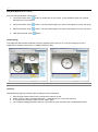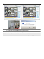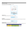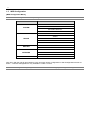
1
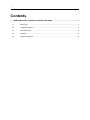
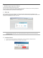
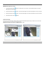
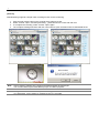
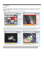
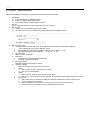
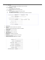
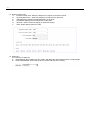
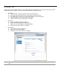
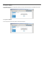
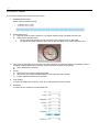
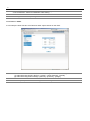
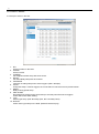
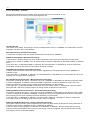
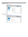
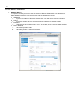
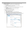
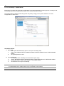
INTERNET EXPLORER WEB MONITORING User Manual 1st Edition : 17 July 2012 Thank You! Before operating the system, please read this User Manual and retain it for future reference. ※ The picture & functions & supplied items might differ according to the specification and model. ※ Contents of this user manual are protected under copyrights and computer program laws. 2 Contents 1. WEB MONITORING THROUGH INTERNET EXPLORER ............................................................. 3 1.1 Web Login ........................................................................................................................ 3 1.2 Installation Active-X .......................................................................................................... 3 1.3 Web Monitoring ................................................................................................................ 5 1.4 Playback ........................................................................................................................... 9 1.5 WEB Configuration ......................................................................................................... 13 3 1. Web Monitoring through Internet Explorer The DVR system has built-in web server by itself. Thus, user can be connected to the system by ordinary web-browser via network for live monitoring, playback or remote configuration without installing Remote Manager software. The web monitoring service works only on Internet Explorer. 1.1 Web Login User is required to put the right IP address in the web browser after getting the web port available by router. After allowing the download and installation of the Active-X file, user can find the log-in page view as below. Default USER ID and PASSWORD are “admin” and “1234”. Note 1.2 Login account information is the same as the DVR’s. If user does not have permission, user cannot operate DVR and “admin” account can only access to configuration menu. Installation Active-X 1. 2. If access correctly with IP address or DDNS domain, Active-X installation message will show. Allow the active-X installation and then it will take a few minutes. . 4 3. If problem on the installation, please change a security option as the follow 1) Go to “Internet option > Security Setting 2) Click “Custom level” and then find “Download signed ActiveX Controls” and “Download Unsigned ActiveX Controls” 3) Select “Prompt” option for both of option. 4. If finishes correctly, the monitoring mode will be shown on the screen. Note Web monitoring screen might be different depending on the DVR model. 5 1.3 Web Monitoring [Web Monitoring] User can get into web monitoring by clicking “WEB MONITORING” button in the right-top corner of the window. In order to connect to DVR, user has to select the number of channel or select “ALL CHANNEL ” as below, and then click “CONNECT” button User can monitor live video in 1, 4, 9 or 16 screen mode. If user wants to see single channel in full screen, then user can make double-clicks of the left mouse button positioned on the live video screen. The image resolution in “Live monitoring” in this web browser is directly transferred from DVR. Therefore, user will see original resolution size set in DVR in single channel mode. In order to get full screen of CIF (352 x 240/288) video size, then user has to click right button of the mouse, and select “Full Screen” menu. Note Reconnection Interval : User can set up the time to reconnection when connection is failed. According to setup time, Web monitoring will try to connect to DVR. Note If Dual Stream is enable at the DVR, Web Monitoring Video will display as the Dual Stream setting. Otherwise, it follows to recording setting. 6 [WEB Monitoring Screen Control] 1. 1Ch Screen Mode: Click “ ” button or double click on the screen. If click the button again, the channel will sequence to next channel. 2. 4Ch Screen Mode: Click “ ” button. If click the button again, the channel will sequence to next 4ch group. 3. 9Ch Screen Mode: Click “ ” button. If click the button again, the channel will sequence to next 9ch group. 4. 16Ch Screen Mode: Click “ ” button. [POS Data Display] If DVR connect to POS system, Web monitoring will show POS data as video overlay. It works at 1ch & 4ch mode only and can be turn on or off by mouse pop-up menu. (Right mouse clicking on the screen => Display POS On or Off) Note POS connection function might not be supported depending on the DVR model. 7 [Archive] Web Monitoring supports a simple video recording function for live monitoring. 1. 2. 3. 4. Click the right mouse button on the channel which wants to record. Select “Archive” option, and then [Recording…] OSD will show to screen with red color To complete the recording, select “Archive” option again. The complete message will show and click “OK” button to open the folder where recorded data saves. Note Archive function supports only 1channel recording and SSF file format type. The recorded data requires Multi-Backup Player or CMS to playback. Note OS higher than Windows VISTA requires the writing permission to save data to local folder. If no permission, even it seems to complete, there is no recorded. 8 [PTZ Control] If PTZ Camera connects to the DVR, it can be controlled through Web Monitoring. The selected channel will mark with yellow border line and can control with “PAN & TILT” button at the right side. PAN & TILT Click 8-way button to move PTZ Camera. ZOOM Click the button to ZOOM in or out. FOCUS Click the button to control focus. PRESET If PTZ camera setup the preset, select the number and click “MOVE” button, it will move to a corresponding location. [Audio and De-Interlace] Audio On/Off Click the audio button to turn on or off, and then selected channel audio will out. De-Interlace Click the De-Interlace button to turn on or off, it is useful to improve D1(720x480/720x576) resolution video quality. Note De-Interlace and Audio out function works on the real-time monitoring mode and playback mode as well. Note Some function might not be supported depending on the DVR model. 9 1.4 Playback [Playback] User can remotely playback the DVR images by clicking “PLAYBACK” button in the right-top corner of the window. In order to connect to DVR, user has to select the number of channel or select “ALL CHANNEL ” and then click “CONNECT” button Playback mode supports 1,4,8,16 channel mode as in the live mode. Playback resolution follows to DVR’s, thus CIF resolution (352x240/352x288) video data displays with original size on 1 channel mode. To make the full size video, click the right mouse button and select “Full Screen” option. Note The Playback video data is not apply to Dual Stream setting.. 10 [Playback Mode Screen control] User can change playback screen mode 1. 1Ch Screen Mode: Click “ ” button or double click on the screen. If click the button again, the channel will sequence to next channel. 2. 4Ch Screen Mode: Click “ ” button. If click the button again, the channel will sequence to next 4ch group. 3. 9Ch Screen Mode: Click “ ” button. If click the button again, the channel will sequence to next 9ch group. 4. 16Ch Screen Mode: Click “ ” button. [POS Display] If the playback data includes POS data, it will play together. And it can turn on or off by mouse pop-up menu (Right mouse clicking on the screen => Display POS On or Off) Note POS connection function might not be supported depending on the DVR model. [Archive] Web Monitoring supports a simple video recording function for playback. 1. 2. 3. 4. Click the right mouse button on the channel which wants to record. Select “Archive” option, and then [Recording…] OSD will show to screen with red color To complete the recording, select “Archive” option again. The complete message will show and click “OK” button to open the folder where recorded data saves. 11 Note Archive function supports only 1channel recording and SSF file format type. The recorded data requires Multi-Backup Player or CMS to playback. Note OS higher than Windows VISTA requires the writing permission to save data to local folder. If no permission, even it seems to complete, there is no recorded. Note De-Interlace and Audio out function works on the real-time monitoring mode and playback mode as well. 12 [Playback time setting] Select the date and time and click [Go] button to playback. The date in bold means it has recorded data [Playback Icon] Play/Pause is toggled and playback speed is shown on the right box [PLAY DST] Check this box to play overlapped images during DST (Daylight Saving Time) period. Overlapped period displays with blue color on the intelli-Search bar. [Intelli-Search bar] User can move the red-vertical line to the time that user wants to search. The colors of the time bar are different by each recording mode. Please, refer to Section 4.3.2 for details on colors. 13 1.5 WEB Configuration [WEB Configuration Menu] Note Menu might be different depending on the model. Main Classification Sub Classification SYSTEM INFO SYSTEM USER FACTORY DEFAULT SYSTEM REBOOT CAMERA AUDIO DEVICE SENSOR MOTION ALARM EXTRA ALARM RECORD CAMERA SCHEDULE NETWORK NETWORK DDNS NOTIFICATION QUICK SETUP QUICK SETUP After log in with the right ID and password, user can make various configuration in Web Configuration window as below. This Web Configuration is only available to “admin” account. Note Do not forget to click [Save] button before move to another setting tap, if setting was changed. 14 1.5.1. System – System Information Setup the information of system. It supports the limited functions through Web. 1. Site Name: A. Insert “Site Name” to distinguish DVR. B. It uses to create backup folder name. C. It is recommended to input English for name. 2. Site ID: it is to recognize DVR ID for using Keyboard or remote controller 3. Date / Time A. Displays the current date and time at the DVR. B. The date and time can be changed to prevent data loss at the DVR side only. 4. Date / Time Format A. The date and time format that is can be changed to suit the user. The format is as follows. i. YYYY: Display the year as four digit.(Ex : 2012) ii. MM: Display the month as two digit (Ex : March => 03, October => 10) st th iii. DD: Display the date as two digit (Ex : 1 =>01, 20 => 20) B. AM / PM, 24H: Select 12-hour or 24-hour. C. Time Zone i. Displays the current time-zone at the DVR. ii. It can be changed at the DVR. D. Day Light Saving: Displays Daylight saving option’s on/off. E. Time Sync Mode: i. None: No setup the time sync with any server. ii. Client : 1. Select “Client’ mode to synchronize to server. 2. The cycle can be adjusted. iii. Server 1. Select “Server” mode to setup server for time sync. 2. The port for communication can be changed, and it must be same between server and client. iv. NTP server 1. Select “NTP server” and input IP address or domain of public NTP sever or other server. 2. “Cycle” is for time sync interval. 3. If it is possible to use the Internet, “pool.ntp.org” can be recommended to use. 4. If the time-zone is not setup, it can be caused of the wrong time. 15 F. Sync Port It is for communication port between server and client. The default is “8002” G. Sync Server i. It is available at the client mode. ii. Input IP address from Time sync server. H. NTP Server i. Input IP address or domain of time sync server. ii. The default is “pool.ntp.org” iii. The public NTP server requires DNS setting for internet connection. i. ii. 5. Remote ID: Displays IR remote controller ID on the DVR. 6. Version: Displays firmware and hardware version on the DVR. 7. Video Signal: Displays video type on the DVR. 8. IP Address: Displays IP address on the DVR. 9. MAC Address: Displays MAC address on the DVR. 10. Keyboard: Displays the connected keyboard on the DVR. 11. Keyboard baud rate: Displays keyboard BAUDRATE on the DVR. 16 12. Display / SPOT-OUT A. Sequence Dwell Time: Setup the dwell time to sequence the DVR channel. B. Spot-Out Dwell Time : Setup the dwell time to sequence the Spot-Out. C. Alpha Blending: Displays the alpha blending on the DVR. D. VGA Mode: Displays the VGA resolution on the DVR. E. Spot-Out : Select channel to display on Spot-Out monitor. F. OSD : Select display option for OSD. 13. HDD FULL: It is a function for HDD full. A. OVER WRITE: When HDD is full, the system will delete the oldest data and then recording again. B. STOP RECORDING: When HDD is full, the system will stop the recording. 17 1.5.2. System – User Setup user account for DVR operation. If you need a limitation for operation, you can create a user account with limited permissions. (“admin”, which is a default administrator, has all permission.) 1. User ADD A. Click “New User” button and input the user ID and password. B. After setup the permission and click “Add” button to add a new user. C. The added user can access to remote software with the same permission. D. After user addition, click “Save” button to complete. E. “admin” account can only create user on the web. 2. User Edit A. Click “Edit” button to edit user setting. B. Edit the user setting and click “Edit” button. C. “admin” account is available to change password. D. After edit, click “Save” button to complete. 3. User Delete A. Click “Delete” button to delete user. B. “admin” account can not delete. C. After delete, click “Save” button to complete. Note Do not forget the password of “admin”. If lost the password, please contact to manufacturer and get help. 18 1.5.3. System – DEFAULT It is to initialize DVR setting. If having factory default, the access to Web monitoring is not available because DVR IP address is changed. 1.5.4. System - REBOOT It is for remote reboot. After reboot, please re-start Internet Explorer. 19 1.5.5. Device – Camera It is for setup camera color values and motion area. 1. CAMERA SELECTION: Select camera number to setup. 2. Setup Motion Area A. Select an area for motion detection. The motion detection area is marked with red color. B. Setup motion detection area : i. Click or Click and drag the area for setup the motion detection are on the blank. ii. For delete the motion detection area, click or click and drag on the motion detection area. 3. Title: Input the individual name of DVR. The name would not be applied to system immediately, even if it changes, it will be applied when the DVR system setup file changes as the follows. A. Time / Resolution / rebooting B. 4. Covert A. Setup the covert option to selected camera. B. The normal user except the administrator of the DVR cannot be verified. C. It has a separate permission for the DVR. 5. Color setting: It is setup for Brightness, Contrast, Color, Hue, and Sharpness on the camera. 6. Sensitivity It is setup for the sensitivity of motion detection. 20 Note 1. Click “SET” button to save the changes for video setting. 2. Click “DEFAULT” button to initialize the video setting. Note Menu might be different depending on the DVR model. 1.5.6. Device - Audio It is for setup the audio function on/off and live audio output channel on the DVR.. Note To add audio into video record data, the audio recording channel should be assigned as the follows. (1) Audio Recording On/Off : [Device] – [Audio] – [Audio Channel] - [On/Off] (2) Audio Recording Channel Assign : [Record] – [Camera] – [Assign] Note The two way setup is not available through the WEB configuration. 21 1.5.7. Device – Sensor It is setup for sensor in and out . 1. NO. Sensor number on the DVR. 2. ON/OFF Sensor On/Off. 3. CAMERA the assigned camera setup with each sensor. 4. RELAY the linked Relay setup with each sensor. 5. INTENSIVE Intensive recording setup when sensor triggers. (Max. 30/25fps) 6. Preset PTZ preset setup. If sensor triggers, the connected PTZ camera moves to preset location. 7. DWELL Relay working period setup. 8. PRE-ALARM Recording and camera popup period setup in seconds just before sensor triggers. It links with motion alarm setting. 9. Type Sensor type setup. (N/O: Normally Open, N/C: Normally Close) 10. NOTICE Alarm notice type setup on the DVR. (Buzzer/Camera Popup) 22 1.5.8. Device – Motion Alarm It is the setup for motion alarm. 1. CAMERA Channel on the DVR. 2. ON / OFF Motion Alarm on or off setup. 3. OUT the linked relay setup. 4. INTENSIVE Intensive recording setup when motion detects. (Max. 30/25fps). 5. DWELL Motion alarm working period setup. 6. PRE-ALARM Recording and camera popup period setup in seconds just before motion detection. It links with sensor setting. 7. NOTICE Alarm notice type setup on the DVR. (Buzzer/Camera Popup) 23 1.5.9. Device – Extra Alarm There are several alarm functions available on the system such as SMART, VIDEO LOSS, RECORDING FAILURE and HDD FULL 1. 2. 3. 4. S.M.A.R.T: HDD error alarm VIDEO LOSS: Video Loss alarm RECORDING FAILURE: Recording failure alarm by HDD failure or system error. HDD FULL : Disk Full Alarm A. Disk Usage: Assign the HDD full usage. Note Extra alarm should be setup “ON” for event recording. Note S.M.A.R.T (Self-Monitoring Analysis and Reporting Technology) alarm is for reference to check HDD condition. Even the HDD has error, sometimes it cannot be detected to S.M.A.R.T alarm. Please check the HDD at the DVR regularly. 24 1.5.10. Recording – Camera [RECORD] It is for recording setup on the DVR. 1. CAMERA The channel on the DVR. 2. ON / OFF Select on or off to record. If setup “OFF”, Video will work for live and network transmission, it is not recording. 3. RESOLUTION Select the recording resolution. The available resolutions are the follows. A. CIF: 352*240(NTSC), 352*288(PAL) B. Half D1: 720*240(NTSC), 720*288(PAL) C. D1: 720*480(NTSC), 720*576(PAL 4. FPS A. Select the recording speed for each channel. B. Before set up, please check the [REMAINING FPS], if it is “0”, the recording speed setup is not available. 5. QUALITY Select the recording video quality for each channel. 6. AUDIO A. Select the audio recording channel. B. For no recording, it should be setup [None]. C. If the audio record is not work, please check the audio channel recording setup on [DEVICE] – [AUDIO]. 7. REMAINING FPS It shows the remaining recordable frame per CIF resolution. 25 [Dual Stream] It is a setup for network video transmission. 1. CAMERA The channel on the DVR. 2. RESOLUTION Select the resolution for network transmission in real-time. The selectable resolutions are the follows. A. CIF: 352*240(NTSC), 352*288(PAL) B. Half D1: 720*240(NTSC), 720*288(PAL) C. D1: 720*480(NTSC), 720*576(PAL D. Dual Stream resolution must be less than the recording resolution. 3. FPS A. Select the transmission speed for each channel. B. Before set up, please check the [REMAINING FPS], if it is “0”, the recording speed setup is not available. 4. QUALITY Select the transmission video quality for each channel. 5. AUDIO A. Setup the network audio transmission for each channel. B. It should follow the audio recording channel setting. 6. REMAINING FPS It shows the remaining recordable frame per CIF resolution. 7. NETWORK LIMIT A. It allows user to reduce the image quality for transmission by percentage of the standard quality. B. The lower percentage requires the smaller network bandwidth but the image quality will be worse. On the contrary, the higher percentage requires the bigger network bandwidth but the image quality will be better C. The highest image quality(100%) is same to the standard image quality of record setting. Note The network stream resolution should be set equal to or smaller than recording resolution. 26 1.5.11. Recording – Schedule Set recording schedule for each camera. First, select the camera to set schedule, or “All”. Recording can be set by each hour from 00 through 23 a day. NO COLOR (Off) “Off” means no recording. Even though user set recording frames and on in “CAMERA”, the system will not record anything if user sets “OFF” in SCHEDULE. YELLOW COLOR (Continuous Recording) In continuous recording mode, the system records all the time as set by “CAMERA”. GREEN COLOR (Motion-Detection Recording) In this mode, the system records only when motion is detected in the motion area, and stops recording when motion is not occurred. In addition, user can make motion recording configuration in “MOTION ALARM” of “DEVICE” menu. If user sets “OFF” in “MOTION ALARM” of “DEVICE” and sets “MOTION” in “SCHEDULE”, then the system will record when motion is detected but motion alarm will not be activated. ORANGE COLOR (Sensor-Activated Recording) In sensor mode, the system will record when sensor is triggered only during dwell time as set in “SENSOR” of “DEVICE” menu. If user sets “OFF” in “SENSOR” of “DEVICE” and sets “SENSOR” in “SCHEDULE”, then the system will not record anything even though a sensor is triggered. SKY BLUE COLOR (Continuous + Motion Detection Recording) The system records all the time by “continuous” as set by “CAMERA” of “RECORD” but will switch recording mode to motion configuration as made by “MOTION ALARM” of “DEVICE” if motion is detected in motion area. The system also will notify “motion event” message to Remote Software over the network. If user sets “OFF” in “MOTION ALARM” of “DEVICE” and sets “CONT + MOT” in “SCHEDULE”, then the system will record with continuous recording mode even though motion is detected in motion area. DARK ORANGE COLOR (Continuous + Sensor-Activated Recording) The system records all the time by “continuous” as set by “CAMERA” of “RECORD” but will switch recording mode to sensor configuration as made by “SENSOR” of “DEVICE” if a sensor is triggered during dwell time. The system also will notify “sensor event” message to Remote Software over the network. If user sets “OFF” in “SENSOR” of “DEVICE” and sets “CONT + SENS” in “SCHEDULE”, then the system will record with continuous recording mode even though a sensor is triggered. PINK COLOR (Motion Detection + Sensor-Activated Recording) The system does not record in normal operation but records only when motion is detected as set by “MOTION” of “DEVICE” and a sensor is triggered as set by “SENSOR” of “DEVICE”. If user set “OFF” in both “MOTION” of “DEVICE” and “SENSOR” of “DEVICE”, then the system will record only when the motion is detected but will not record even though a sensor is triggered. And, the system will not notify both motion & sensor to Remote Software. 27 1.5.12. Network – Network It shows the current network setting on the DVR, 1.5.13. Network – DDNS It shows the current DDNS setting on the DVR. . 28 1.5.14. Network – Notification 1. REMOTE NOTIFY The system can notify an event to the IP address of Remote Software PC over the network. Select REMOTE NOTIFY to use this function and set IP address & events. A. ADDRESS i. Input the IP address of Remote Software PC which will receive events notification. B. PORT i. Input Port number which is set at the Remote Software PC. Default is 8003. C. EVENTS i. Select events to be notified. When “ALL” is selected, all of the events will be notified. D. EDIT / DELETE i. Click [EDIT] button to edit. ii. Input the contents and click [EDIT] button to save on the DVR. iii. Click [DEL] button to delete on the DVR. 29 2. EMAIL NOTIFY ADD / EDIT The system can make an event notification to the e-mail address registered in the DVR. Select E-MAIL NOTIFY to use this function and set e-mail address & events. A. EMAIL ADDRESS i. Click [NEW EMAIL] button to add new email account for registration. ii. Input the email address to receive the event. B. EVENT i. Select events to be notified. When “ALL” is selected, all of the events will be notified. ii. If it is sensor or motion alarm, the email includes still image shot. C. EDIT / DELETE i. Click [EDIT] button to edit. ii. Input the contents and click [EDIT] button to save on the DVR. iii. Click [DEL] button to delete on the DVR. D. SMTP Setup SMTP server information to send email. i. SMTP: Input SMTP server address. ii. PORT: Input SMTP sever port. iii. USER: Input User in case the log-in is required to SMTP server. iv. PASSWORD: Input Password in case the log-in is required to SMTP server. v. FROM: Input sender’s e-mail address what will show on the receiver’s email. vi. USE SSL AUTHENTICATION : In case the SMTP server requires SSL authentication 30 1.5.15. Quick Setup – QUICK SETUP Quick Setup is to help user make easy configuration for recording resolution, recording speed, recording mode, recording quality and recording periods based on the capacity of HDD installed. The setting made by QUICK SETUP will get the first priority to apply on the system whatever user sets configurations in other menu. USE QUICK SETUP A. RECORD i. Check [USE QUICKSETUP] option to use quick recording setup. ii. Select “RECORDING RESOLUION/RECORDING FPS/RECORDING QUALITY/RECORDING MODE”. iii. Click [SAVE] button to save. B. DUAL STREAM i. Check [USE DUAL STEAM] to use dual stream quick setup. ii. Select “NETWORK RESOLUION/NETWORK FPS/NETWORK QUALITY/NETWORK AUDIO iii. NETWORK LIMIT : please refer Chapter “1.5.10”(Dual Steam). iv. Dual Stream is for only live monitoring. Note If the camera is set as “OFF” in the camera setting menu, it will not be recorded even if it is set in the Quick Setup menu. Please check if any of cameras is not recorded. Note The network stream resolution should be set equal to or smaller than recording resolution. 31 1.6 Q&A Q: Web Connection is fine, but no video display . 1) It is a difference between WEB Configuration port and video transmit port. Video transmission port uses TCP/IP port(Default port) to display, and WEB Configuration port is Web port. 2) Please check the router port forwarding setting. If not open, it can be caused problems for video. 3) If there are many connections to DVR, it may have the problem. Please disconnect and reconnect to DVR. Q: Video quality is not good. 1) The network condition is related to image quality, so please check the network status. Q: DVR에서 WEB port is changed on the DVR side, how can access to DVR through WEB Monitoring? 1) Access with IP address : http://IP Address:PORT EX. http://123.123.123.123:8080 2) Access with DDNS : http://DDNS domain name EX. http://test123.cctv-link.net 3) Access with DDNS of Dyndns : http://DDNS domain name:PORT EX. http://test123.dyndns.com:8080 Q: I would like to have a monitoring in other browser than IE. 1) Because Active-X, it is not available to have a monitoring on other browser than IE. 2) Other browser only supports WEB Configuration. Q: There is an error message as the follows. LibCGI Warning: Cannot redirect. Headers already sent 1) It is a message what occurs while log in, if click the log in button again. 2) Althogh WEB CGI is not closed, if click the log in button, the message can be popup. 3) Closed all IE and restart IE again. 4) If still have same problem, please delete temporary files and cookie, and then try to connect again. Q: Even installed Active-X, Active-X installation starts again. 1) Active-X is built on a 32-bit. 2) Active-X may not be installed properly on Internet Explorer 64bit or 3rd party browser with plug-in.