1
INSTALLATION AND WIRING
Guide to the Pins for Connection
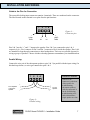
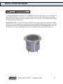
The removable locking input connector contains 4 terminals. These are numbered on the connector.
The label located on the terminal cover plate lists the pin functions.
1
2
3 4
-
+
LOOP
THRU
+
-
IN
IN
Figure 8 –
Connector pins
LOOP
THRU
Pins 2 & 3 are the “+” and “-” inputs to the speaker. Pins 2 & 3 are connected to pins 1 & 4
respectively (i.e. Pin 1 connects to Pin 2 and Pin 3 connects to Pin 4) inside the speaker. Pins 1 & 4
are intended as loop-through connections to other loudspeakers. There are two possible layouts for
wiring a group of speakers. Choose whichever hookup pattern accommodates your installation best.
Parallel Wiring:
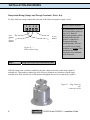
Connect the wire pair of the subsequent speaker to pins 2 & 3 (in parallel with the input wiring). In
this hook-up scheme, no wires get connected to pins 1 & 4.
1
2
3 4
PARALLEL WIRING
+
From amplifier
or previous
speaker
_
To next
speaker
_
+
Whenever the
connector is pulled out
of the speaker for
troubleshooting,
subsequent speakers
will stay connected. It
can be useful during
troubleshooting to be
able to disconnect a
single speaker at a time.
Figure 9 –
Parallel wiring
CLOUD 4 and CLOUD 6 – Installation Guide
7