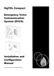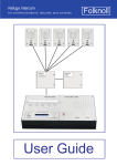
1
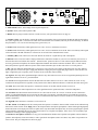
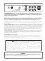
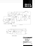
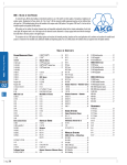
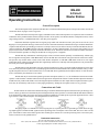
MS-200
2-Circuit
Master Station
Operating Instructions
General Description
The best description of the operation of the MS-200 is contained within the descriptions of the operation of the controls and
connections shown on pages 2 and 3. In general . . . . .
The MS-200 with its external power supply is intended to be the central control point for two separate circuits of outstations.
Outstations can be portable headset stations (usually referred to as belt packs), fixed headset stations, loudspeaker stations, remote
stage manager stations, or additional MS-200’s (less their power supplies).
Outstations should be organized into two logical groups which will each then become a party-line circuit. The two (A &
B)groups of 3 rear panel male XLR-type connectors are used to connect the outstations to the MS-200 using 2-conductor shielded microphone cable fitted with 3-pin XLR-type connectors. As many as three runs (on each circuit) may be started at the MS-200, but outstations usually have In and Out connectors allowing outstations to be daisy-chained together. An accessory SB-1 splitter box (see
page 4) may be used to combine sub-groups of stations with either circuit. The stations on each circuit will be in constant communication with each other regardless of settings at the MS-200 (as long as power is supplied).
The MS-200 may communicate with both groups (circuits) of remote stations separately or simultaneously, without tying
the two together. Pressing either or both Circ buttons connects the MS-200. These buttons turn green when the connection is made.
The operator may monitor either or both circuits while his/her microphone is either On or Off. Each circuit has its own signal
lamp/button which, when pressed, lights all the other signal lamps on that circuit. The lamp will also light whenever any outstation on
the circuit presses their signal button.
The MS-200 provides XLR inputs (see page 3) and level controls (see page 2) for audio signals originating at a mixer (line
level) or directly from a microphone (mic. level) This program will then be heard on the MS-200’s speaker or headset, and, by switching the front panel selectors, to either or both circuits. Level at the MS-200 is regulated by the front panel controls. Level at the outstations is controlled by the outstation’s level control.
The MS-200 may be used with an optional gooseneck microphone (LSM-1, 2 or 3), in combination with its built-in loudspeaker, or with a headset or handset. When used with a gooseneck microphone the sidetone control should be adjusted to minimize
feedback. In noisy situations the LSM-2 noise canceling microphone should be used. The output of the microphone (headset or gooseneck) may be momentarily redirected to a remote paging amplifier by shifting the front panel switch to its Page position.
Connections and Cable
Remote stations are connected to the MS-200 using 2-conductor shielded microphone cable fitted with 3-pin XLR-type connectors. Cable type and size are determined by the total length of all runs, but in general we recommend that the individual conductors
be no smaller than 22 AWG. For longer runs and for permanent installations in conduit, please request the Applications Note ‘Cable
Type and Size’ from Technical Projects. Pin configurations are shown below.
The paging output is a combination 3-circuit (tip/ring/sleeve) 1/4"phone jack and a 3-pin XLR-type female XLR. The paging output appears as a balanced 600W signal across the tip and ring of the 1/4"and pins 2 and 3 of the XLR. The sleeve of the 1/4’ and
pin 1 of the XLR are connected to chassis ground. The normally open contacts are across the tip and ring of the 3.5mm stereo jack,
with no connection to the grounded sleeve.
Production Intercom Inc.
Printed in USA
P.O. Box 3247, Barrington, IL 60011-3247
Voice: (847) 381-5350 Fax: (847) 381- 4360 Sales/Technical Assistance (US & CAN): (800) 562-5872
e-mail: [email protected] Web: beltpack.com
Rev. 03/99
LinkÙ
10
Circ A
Production Intercom
Circ B
A
8
Off on
3
Off on
6
5
1
15
12
Circ
Circ
24VDC
11 Listen 14
Main
Mic
Page
On
4
Spkr
B
Signal
Signal
9
2
MS-200 Master Station
13
7
Line
Mic
Off
Level
16
17
1. Main: On/off control - turns orange when on, push on/push off
2. Speaker: Turns yellow when speaker is On.
3. Blank: Remove plug to install switch for override accessory (See optional accessories on page 4).
4. Auxiliary (Line): Use this knob to control the loudness of an auxiliary line level program at the MS-200 and also throughout
the system. Typically this is a feed from an audio mixer which enables crew members, who may be far from the stage, to monitor
the performance, or as a cue feed to dressing rooms, green rooms, etc.
5. Switch: Sends the auxiliary audio signal (line level or mic. level) to outstations on circuit A.
6. Switch: Sends the auxiliary audio signal (line level or mic. level) to outstations on circuit B. Note: The auxiliary audio signal
will not be heard at the MS-200 unless it is directed to one or both of the communications circuits.
7. Auxiliary (Mic): This control serves the same function as #4 but for a signal directly from a microphone.
8. Sidetone: This recessed screwdriver-adjust potentiometer controls the loudness of your own voice heard in your own ear. It
does not affect the level heard at other stations. . Normal headset position is about 2 o’clock. When using the MS-200 with an
accessory gooseneck microphone, the sidetone adjustment should be fine-tuned to minimize feedback. This is a ‘null’ control,
that is,the position of greatest sidetone rejection will be found somewhere just on either side of the 12 O’clock position.
9. DC: This LED indicates that the MS-200 is receiving DC power from its power supply. If this lamp goes out it may indicate
that the protective circuit in the power supply has shut down. Unplug the power supply then plug it back in. If the LED does not
light, or lights then goes out quickly, check for short circuits in the inter-station cabling.
10. Signal A: The lamp in this push-button lights whenever any other station in circuit ‘A’ has its signal lamp button pressed. To
signal other stations in circuit ‘A’, press this button.
11. Circuit A: Pressing this button connects the MS-200 to the other stations in circuit ‘A’. Other stations in circuit ‘A’ may
communicate among themselves regardless of the position of this button. When the MS-200 is connected, the button turns green.
12. Link: This switch allows the operator to combine the stations on circuit B with the stations on circuit A.
13. Listen Level: This control adjusts the level of the signal heard in the operators headset, or from the loudspeaker.
14. Circuit B: This button has the same functions as #11 above but for circuit ‘B’. Circuits ‘A’ and ‘B’ are not connected together, even though both buttons are pressed in at the same time. The operator of the MS-200 may speak and listen to both circuits simultaneously, but stations on circuit ‘A’ may not communicate with stations on circuit ‘B’ and vice-versa unless the Link
switch is switched in.
15. Signal B: Same functions as #10 above, but for circuit ‘B’.
16. Mic. Switch: In the Off position, this switch permits the operator to continue to monitor either or both circuits without being
heard at the remote stations. In the Page position, the output from the microphone preamplifier is directed through a high quality
audio transformer to an output jack on the rear panel. In this way the headset microphone may be used to page through a separate
paging amplifier, eliminating the need to remove the headset to use a separate microphone. It also closes a set of normally open
contacts for switching a remote paging amplifier.
17. Headset or microphone connector: Use any good communications headset with a dynamic microphone of about 200W impedance, and earphone(s) from 8W to 400W, or with a gooseneck microphone (LSM-1 or LSM-2). Any make of 4-pin XLR connector will fit. The pin configuration is shown on page 1.
Press
Paging Output
Normally
Open
To/From
Contacts
MSM-2 or 3
Aux Input
Mic Level
È
6
thu Þ
8
4
1
3
600W Unbalanced
2
CE
Manufactured in the U.S.A.
by Production Intercom Inc.
Barrington, Illinois 60010
Press
Aux Input
Line Level È
5
From
5
A
A
A
9
thuÞ
11
12
5
External
24 VDC Supply
B
B
B
1. Normally Open Contacts: This 3-circuit, 3.5mm jack is connected to a pair of contacts which are normally open. They close
when the front panel microphone switch is moved to the Page position. It is intended to be used in conjunction with the Paging
Output (#2), for activating a paging amplifier.
2. Paging Output: This unique jack combines a 3-circuit phone jack and a 3-pin XLR. It provides for connection to a paging
amplifier. Output is 600W , balanced and appears across the tip and ring of a phone plug or pins 2 & 3 of an XLR. The sleeve of
the phone plug and pin 1 of the XLR are connected to chassis ground. When the front panel microphone switch is moved to the
‘Page’ position, the output of the microphone preamplifier is routed through a high quality audio transformer to this jack.
3. Link (MSM-2/3): The MSM-2 and MSM-3 add additional circuits to the MS-200. The MSM-2 provides circuits ‘C’ and ‘D’.
The MSM-3 provides circuits ‘C’, ‘D’, ‘E’ & ‘F’. The cable for connection to this 9-pin D-Sub connector is provided with the
MSM-2 and MSM-3.
4. Auxiliary Input (Microphone): The output of a low impedance microphone connected to this 3-pin female XLR jack will be
heard throughout the intercom system. Level is controlled at the front panel. Typical application is to connect a microphone hung
over the stage so that the technical crew and backstage performers can monitor the performance regardless of their distance from
the stage. The auxiliary signal can be routed to circuit A, circuit B, both, or neither, using front panel switches. This input is unbalanced. Connect pin 1 to the shield in the microphone cable along with one (probably black) conductor. Connect the other
(probably white) conductor to pin 2. No connection is made to pin 3.
5. Auxiliary Input (Line): This input performs the same function as #4 above, but for an unbalanced line level signal, typically
from a mixer or preamplifier. This input has its own front panel level control and may be used simultaneously with input #4.
6-7-8. Circuit ‘A’: To/from remote stations.
9-10-11. Circuit ‘B’: To/from remote stations.
12. Power Input: Connect the outboard power supply to this 3-pin jack. You may also connect this 3-pin jack to any of the 3
XLR outputs on the back of a PS-1A power supply, or the single jack on a PS-1B. Whatever the source, the MS-200 requires
well filtered, hum-free 24VDC. Pin connections are shown on page 1.
☛
Even if you don’t read anything else, please read this!
The most common cause of poor system performance or failure is the accidental grounding of the
shield in the 2-conductor shielded microphone cable used to interconnect intercom stations. In
this application the shield performs 4 functions: as the shield; as the zero volt reference for the
+24VDC on pin 2; as the zero volt reference for the +12VDC which appears on pin 3 when signal
lamps are activated, and as the return for the audio signal on pin 3. Check carefully that the shield
is not connected to the ground lug in XLR connectors, or touching a grounded metal surface inside
any junction boxes which are part of the system.
Support!
If we can help you to lay out your headset intercom system, or maximize the flexibility of your equipment, please call. Technical support will be cheerfully provided.
Optional Accessories
1. OG904 Override Generator Module:
Production Intercom talkback loudspeaker stations contain circuitry which responds to an ultrasonic signal by overriding their
front panel switches and controls to preset positions and levels. This feature may be used to restore volume at a speaker station
which has been accidentally turned down; to mute a loudspeaker station during selected messages, and; to switch a loudspeaker
station back to its Listen mode from Off or Talk. When an OG904 is installed in the MSM-1 it provides the triggering signal for
the override function. The output of the OG904 may be wired internally to affect either or both circuits. A front panel pushbutton switch which is part of this kit may be either latching or momentary. The OG904 is available factory installed or as a kit.
Installation is primarily mechanical, with some soldering required. Set-up requires a frequency counter.
2. MSM-2 and MSM-3 Additional Circuits Modules:
These units are housed in one rack-unit high cabinets. The MSM-2 adds two additional circuits to an MSM-1. The MSM-3 adds
4 additional circuits to an MSM-1. Both are supplied with a cable to interconnect to the MSM-1.
3. Plain, Rack-Mount and Handle Side Panels:
MSM-1’s are shipped with rack mount side panels, 1U (1.75") high. Plain side panels are available, as are side panels incorporating carry handles. The MSM-1 may be ordered with your preference of side panels, or replacement side panels may be ordered
as an accessory.
4. Gooseneck Microphones:
Two gooseneck microphones are available for the MSM-1. Both are fitted with 4-pin XLR-type connectors and may be plugged
directly into the front panel 4-pin XLR. In this configuration it is assumed that the operator will be listening via the MSM-1’s accessory rack-mount speaker or similar. The LSM-1 is an omni-directional microphone and should operate successfully in most
applications. The LSM-2 is a close-talking, noise-canceling microphone intended for noisy locations. The key phrase is closetalking....this microphone is intended to be used at less than an inch from the operators lips. In most environments an LSM-1
gooseneck microphone can be used with the accessory speaker constantly switched On in a full-duplex (simultaneous talk/listen)
mode and at a satisfactory listening levels without feedback. This may require adjustment of the front panel sidetone control (See
page 2, Item #8.) If feedback occurs before the speaker level is sufficiently high, the front panel microphone On/Off switch can
be used; or substituting an LSM-2 should be considered.
5. SB-1 Splitter/Isolator:
The SB-1 Splitter/Isolator is packaged in the same extrusion as our belt packs . It may be used as a 1-in/4-out splitter or, when its
isolate button is pressed in 1-in/2+2 out with two outlets being part of the inputted circuit and the two others creating an all new
isolated communications circuit.
6. BP-2 Belt Pack:
Though not technically an accessory to the MSM-1, the BP-2 should be considered whenever an additional branch circuit needs
to be created from one of the existing stations on circuit A or circuit B. A common example is an isolated spur connecting
follow-spot operators to a lighting director who is himself on one of the MSM-1’s two prime circuits.
Specifications
Electronic:
Microphone Impedance: 200W Ideal, 30~1kW O.K.
Earphone/Speaker Impedance: 8~4kW
Power requirement: +24~30VDC
Line termination impedance: Audio - 200W, DC-5kW
Microphone level aux. input:
Impedance: 200W Unbal.
Sensitivity: -60dBu Max.
Line level Aux. Input:
Impedance: 10kW unbalanced
Sensitivity: -26dBu
Mechanical:
Standard 19" Rack Mount: Height- 1U
(1.75"/44.45mm)
Supplied with rack mount flanges integral to side
panels.
Plain side panels available for table top use.
Dimensions (H x W x D) excluding rack mount
flanges:
1.68 x 16.88 x 7.00in. 42.67 x 428.75 x 177.8mm.
Weight: 6.25lbs./2.835kg.
Warranty Information
Production Intercom products are covered by a limited one-year warranty against defects in materials
and/or workmanship. Full details of the warranty are available from Production Intercom, or your dealer.