1
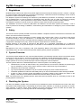
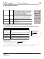
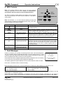
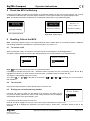
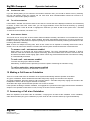
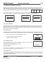
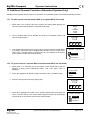
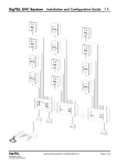
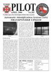
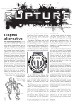
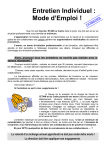
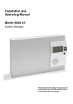
SigTEL Compact Emergency Voice Communication System (EVCS) Operator Instructions Approved Document No. DAU0000082 Rev 4 SigTEL Compact Operator Instructions AN EXPLANTION OF TERMS AND DEFINITIONS USED IN THESE INSTRUCTIONS IS LISTED IN SECTION 16. Contents 1 REGULATIONS ............................................................................................................................................................. 3 2 SAFETY ........................................................................................................................................................................ 3 3 SYSTEM OVERVIEW .................................................................................................................................................... 3 4 DISABLING THE SYSTEM .............................................................................................................................................. 3 5 MCU INDICATORS & DISPLAY...................................................................................................................................... 4 5.1 5.2 EXTERNAL INDICTORS .....................................................................................................................................................4 THE DISPLAY .................................................................................................................................................................4 6 MCU CONTROLS.......................................................................................................................................................... 5 7 FAULT MESSAGES ....................................................................................................................................................... 5 8 CHECK THE MCU IS WORKING ..................................................................................................................................... 6 9 HANDLING CALLS AT THE MCU ................................................................................................................................... 6 9.1 9.2 9.3 9.4 9.5 9.6 TO ANSWER A CALL ........................................................................................................................................................6 TO END A CALL ..............................................................................................................................................................6 ENDING ONE CALL AND ANSWERING ANOTHER.....................................................................................................................6 CONFERENCE CALLS........................................................................................................................................................7 TO CALL AN EXTENSION ...................................................................................................................................................7 AUTO-ANSWER FEATURE .................................................................................................................................................7 10 MAKING A CALL FROM AN OUTSTATION .................................................................................................................... 7 11 ANSWERING A CALL AT AN OUTSTATION ................................................................................................................... 7 12 ADDITIONAL OPERATOR FUNCTIONS .......................................................................................................................... 8 12.1 12.2 12.3 12.4 12.5 13 CLEAR RECENT CALLS ......................................................................................................................................................8 SYSTEM RESET...............................................................................................................................................................8 SOFTWARE VERSION .......................................................................................................................................................8 ALT. MASTERS...............................................................................................................................................................8 TAKE CONTROL..............................................................................................................................................................8 ADDITIONAL OPERATOR FUNCTIONS (NETWORKED SYSTEMS ONLY) ......................................................................... 9 13.1 TO TAKE CONTROL FROM THE MASTER MCU AT A REPEATER MCU (CALL MODE) .......................................................................9 13.2 TO GIVE CONTROL TO A REPEATER MCU FROM THE MASTER MCU (NO-CALL MODE)..................................................................9 13.3 TO TAKE CONTROL FROM THE MASTER MCU AT A REPEATER MCU (NO-CALL MODE) ...............................................................10 14 OFF-HOOK DETECTION .............................................................................................................................................. 10 15 MONITORING TOILET ALARMS ................................................................................................................................. 11 16 TERMS AND DEFINITIONS ......................................................................................................................................... 12 ©Errors and omissions excepted. The manufacturer of this product operates a policy of continuous improvement and reserves the right to alter product specifications at its discretion and without prior notice. All of the instructions covered in this manual have been carefully checked prior to publication. However, no responsibility can be accepted by the manufacturer for any inaccuracies, or any misinterpretations of an instruction or guidance note. SigTEL Emergency Voice Communication System Approved Document No. DAU0000082 Rev 4 Page 2 of 12 SigTEL Compact Operator Instructions 1 Regulations Disabled refuge systems are called for by DETR Approved document B (Fire safety) volume 2, section 4, Design for vertical escape and BS 5588 Fire precautions in the design, construction and use of buildings, Part 8, Code of practice for means of escape for disabled people. Fire telephone systems for buildings are called for by BS 5588 Fire precautions in the design, construction and use of buildings Part 5; Code of practice for firefighting stairs and lifts, Part 10; Code of practice for shopping complexes and Part 11; Code of practice for shops, offices, industrial, storage and other similar buildings. Fire telephone systems for sports venues are called for by the Guide to safety at sports grounds. The installation of EVCS is covered by BS 5839-9 Fire detection and fire alarm systems for buildings – Part 9: Code of practice for the design, installation, commissioning and maintenance of emergency voice communication systems. 2 Safety The EVCS is safe to operate provided it has been installed in compliance with the manufacturer’s instructions and used in accordance with this instruction. DO NOT open the control enclosures as mains voltages are present inside. There is no need to open these enclosures except to carry out maintenance, or remedial work. Such work must be carried out by competent service personnel who are fully conversant with the installation manual for this product. If equipment is damaged in any way, advise the person responsible for the EVCS at the site. Regular servicing of the EVCS is required by BS 5839-9, by a competent organisation on a continuous maintenance contract. A fully itemised report of the status of the installation should be obtained at least once a year. Management of the site is required by law (The Regulatory Reform (Fire Safety) Order 2005) to appoint a responsible person to ensure the EVCS (and other safety systems) remains operational. 3 System Overview The EVCS provides reliable two-way communication between a permanently manned control room and key points on the site in a fire emergency. The EVCS comprises of fire telephone and/or disabled refuge systems. Fire telephone systems are for use by trained people as part of the fire safety procedures at the site. Disabled refuge systems are for use by untrained people communicating with a trained Operator. The two systems differ from a standard telephone or intercom system in the following ways: Outstations do not have to dial the MCU, they call the MCU as soon as their handsets are picked up (at Type A outstations), or the ‘Push to Call or Answer’ button is pressed (at Type B outstations) Outstations cannot call other outstations Type A (fire telephone) outstations may be in locked housings to prevent unauthorised access The EVCS operates from mains and has battery back-up in case of mains failure so that it is always available If there is a fault, a buzzer sounds intermittently at an MCU. Details of the problem are shown on the display. If the fault is not rectified the fault buzzer resounds after a period of 6 hours. Note: The system also has a disabled persons toilet alarm (DPTA) interface which is a secondary function to the primary purpose of the EVCS. 4 Disabling the System If an MCU is installed in a public area, the system may be disabled to prevent unauthorized use. If this is the case, the system will be enabled either, automatically when the fire alarm operates, or manually by operation of a breakglass call-point, or similar control. When disabled, the EVCS continues to check for faults but the MCU are suppressed from making, or receiving calls until an external trigger is applied. SigTEL Emergency Voice Communication System Approved Document No. DAU0000082 Rev 4 Page 3 of 12 SigTEL Compact Operator Instructions 5 MCU Indicators & Display 5.1 External indictors Indicator Disablement System Fault Colour Amber Amber PSU Fault Amber General Fault Amber Power 5.2 Green What this means The EVCS is powered up and checking for faults but the MCU is disabled from making, or receiving calls, until an external trigger is applied, e.g. from a fire alarm panel. This is not a fault indicator. This function is used to stop nuisance/malicious use of the EVCS until the system is required. There is a problem with the microprocessor. If this indicator cannot be extinguished, there may be a serious problem with the microprocessor. Contact the service company responsible for the EVCS. There is a fault with the mains power supply or backup batteries. There is a fault on the EVCS. The display will show more information. Power (mains or battery) is present. Disablement System Fault PSU Fault General Fault Power The display The display shows call status, system information, fault information and uses the following graphic symbols: Graphic symbol What this means MCU □ Rcnt Calls LCU > Type A (fire telephone) outstation Extension 5 Extension 6 Type B (disabled refuge) outstation wc > Extension 2 Disabled persons toilet alarm (DPTA) The display entry is highlighted, ready to be selected Display conventions Standard / non-active displays are shown normally, e.g. ‘ Active displays are shown reversed, e.g. ‘> Extension 5’ Extension 2’’ The flashing graphic symbol in front of an extension name means this extension is calling the MCU, or the MCU is calling the extension. The display’s red backlight also flashes when an outstation is ringing in. A reversed graphic symbol in front of an extension name means you are connected to this extension. SigTEL Emergency Voice Communication System Approved Document No. DAU0000082 Rev 4 Page 4 of 12 SigTEL Compact Operator Instructions 6 MCU Controls Note: The controls inside the MCU are for use by the service company responsible for the EVCS. Under no circumstances should these internal controls be accessed by Operators. The MCU’s external control buttons are located on its keypad. They are multi-purpose and their functions depend on the MCU’s current status. Note: The numbers 1, 2, 3, & 4 are used for entering security PIN codes using the keypad (by responsible persons only). This code will be provided by the system installer. Button label What this means Up Down CALL / ACCEPT Select HOLD ESC back to previous display & Lamp test FUNCTION &1 Additional functions & security PIN code entry Telephone directory & security PIN code entry DIRECTORY &2 SILENCE BUZZER &3 4 Silence buzzer & security PIN code entry Security PIN code entry CALL / ACCEPT HOLD DIRECTORY FUNCTION SILENCE BUZZER 1 2 3 4 When to press this button Used to move up and down lists (e.g. phone lists) and menus (e.g. User Options menu). When the MCU’s handset is off-hook press this button to either make an outgoing call to an extension, or accept an incoming call from an extension. Also, selects menu options. When the MCU’s handset is off-hook press this button to disconnect the current caller. When the MCU’s handset is on-hook press this button to escape back to a previous menu. Note: To perform a lamp and buzzer test, press and hold this button. Used to access to the ‘User Opts’ menu (see sections 12 & 13). With the MCU’s handset off-hook, toggles between a full list of extensions and a list of recent calls from extensions (if any). Note: The recent calls list is automatically cleared after a set time period (settable between 6 to 24 hours by a system engineer). Also, can be manually cleared. Used to silence the MCU’s internal buzzer. 7 Fault Messages Faults on the EVCS are normally non-latching and will clear if the fault disappears. The only exception being a watchdog fault which occurs at initial power-up, or after a system reset and stays latched until manually cleared. Normally this fault clears when accepted and the MCU reverts to normal operation. If the EVCS has been configured previously and any extensions are now missing, or are incorrectly connected the relevant faults are displayed. The display (right) show typical displays but may have a different number of faults. EVCS 2 Faults Press Accept To View Press CALL / ACCEPT button to view the fault(s). Each fault display has two lines. The format depends on whether the fault relates to an extension or not. Format 1: Extension faults Format 2: Non-extension faults Line 1 - Extension name Line 1 - Fault description, e.g. mains fail Line 2 - Fault description Line 2 - Blank When a fault occurs, the relevant fault indicator is lit and a buzzer sounds intermittently at the MCU (or at the master MCU on a networked system). Some faults may require investigation, or assistance from the service company responsible for the EVCS. If required, contact them directly for assistance quoting the exact nature of the fault which is shown on the display. SigTEL Emergency Voice Communication System Approved Document No. DAU0000082 Rev 4 Page 5 of 12 SigTEL Compact Operator Instructions 8 Check the MCU is Working If the EVCS is healthy, the MCU’s red indicator on the handset cradle is lit, the green Power indicator is lit, no fault or disablement indicators are lit and the display shows the current system status, see typical displays below. Note: The display at the MCU is different for a networked system and a non-networked system. EVCS MASTER Master is Controller 1 S ys t em H ea l th y S ys t em H ea l th y S ys t em H ea l th y Non-networked MCU Networked ‘master’ MCU Networked ‘repeater’ MCU 9 Handling Calls at the MCU Note: This section applies to both a non-networked MCU and the master MCU on a networked system. Additional call handling facilities are available for a networked system, see section 13. 9.1 To answer a call When an extension calls in to the MCU, the ringer sounds and the display’s red backlight flashes. The MCU’s display shows the name of the calling extension (or networked MCU), see examples below. Rcnt Calls > Rcnt Calls > Extension 2 Repeater MCU Note: denotes MCU and is only seen on a networked system. Lift the MCU’s handset and press CALL / ACCEPT button to answer the call. If necessary, press ▲ and ▼ to highlight the extension you want to talk to and press CALL / ACCEPT button to answer the call. The display’s red backlight returns to normal. The symbol ( or or or wc) will be reversed (i.e. or or or wc) meaning you are connected to that outstation. 9.2 To end a call Hang up the MCU’s handset or press HOLD button to end the call. 9.3 Ending one call and answering another If another call comes in whilst you are talking to an extension, the MCU will not ring, but the display indicates the name of the calling extension and the display’s red backlight flashes. See typical display, right. Rcnt Calls > Extension 2 Extension 5 To end the first call and answer the new one: Press ▲ and ▼ to highlight the call you want to end. Press HOLD button to end the call. Press ▲ and ▼ to highlight the extension you want to talk to. Press CALL / ACCEPT button to talk to the extension. SigTEL Emergency Voice Communication System Approved Document No. DAU0000082 Rev 4 Page 6 of 12 SigTEL Compact 9.4 Operator Instructions Conference calls If you are already talking to one extension and another extension calls, you can talk to both at once by selecting the new call without ending the original call. No more than three outstations/MCU should be involved in a conference call as audio quality is reduced. 9.5 To call an extension Lift the MCU’s handset. If there have been recent calls, the recent calls list is displayed otherwise, the full directory is shown. If there have been recent calls, you can toggle between recent calls and full directory by pressing DIRECTORY button. Press ▲ and ▼ to highlight the extension you want to talk to then press CALL / ACCEPT button to call. To clear the recent calls list, see section 12.1. 9.6 Auto-answer feature The EVCS can be set up with an Auto-Answer feature enabled. Normally, this feature is not enabled but can be programmed by a system engineer. When enabled, the MCU automatically answers an incoming call when its handset is picked up, rather than the Operator picking up the handset and manually selecting the extension of the incoming call before answering. Note: If there are multiple incoming calls, there is less control for an Operator to manually select which call to answer. As a rule, when Auto-Answer is enabled, the lowest system numbered extension is answered first. To answer a call - auto-answer enabled When there is an incoming call, lift the MCU’s handset. The call is automatically answered. If another extension calls into the MCU and requires answering, place the handset back on-hook to end the first call and wait for the MCU to start ringing again. When it does ring, lift the handset and the next extension calling in is automatically answered. To end a call - auto-answer enabled To end a call, hang up the MCU’s handset. Alternatively, if HOLD button is pressed you have the option of selecting an extension to ring. To call an extension - auto-answer enabled This is the same procedure as described in section 9.5. 10 Making a Call from an Outstation There is no need to dial from an outstation as the system automatically calls the Operator at the MCU. At Type A outstations, lift the handset and a double ‘beep-beep’ ringing tone sounds in the earpiece. At Type B outstations, press the ‘Push to Call or Answer’ button – a double ‘beep-beep’ ringing tone sounds in the loudspeaker and the Call in Progress indicator is lit steady. At the MCU the ringer sounds and the Operator can choose to answer. If the Operator is talking to another outstation, an engaged tone (continuous short pips) sounds at the outstation’s earpiece. The Operator knows there is a call, so stay on the line until it is answered. 11 Answering a Call at an Outstation When the Operator at the MCU calls an outstation, a ringing tone is heard at the outstation. At the outstation, either lift the handset (at Type A outstations) or press ‘Push to Call or Answer’ button (at Type B outstations). SigTEL Emergency Voice Communication System Approved Document No. DAU0000082 Rev 4 Page 7 of 12 SigTEL Compact Operator Instructions 12 Additional Operator Functions Additional Operator options are available at the MCU by pressing FUNCTION button (with the handset on-hook). Note: Some Operator functions require a security PIN code entering. This code can only be changed by the EVCS service company. Therefore, ensure that the security PIN code is held by a responsible person and NOT lost. The default code is 2222 but keep a record of the code in the boxes, right. With the MCU’s handset on-hook, press FUNCTION button. The ‘User Opts’ menu is displayed. Note: The ‘User Opts’ menu for a networked MCU is different to a non-networked MCU (see below): User Opts User Opts >Clr Rcnt Calls >Clr Rcnt Calls Reset System About... Non-networked MCU User Opts >Take Control About... Alt. Masters Reset System About... Networked ‘master’ MCU Networked ‘repeater’ MCU 12.1 Clear recent calls To make it easier to call back to outstations, the system keeps a record of incoming calls for up to 24 hours after the system was last used. To manually clear this list press FUNCTION button and select ‘Clr Rcnt Calls’ option. Note: The system can be set up to automatically clear the recent call list after a set time period (between 6 to 24 hours). This is set up by a system engineer. 12.2 System reset This option provides a clean restart to the system and is used for an emergency recovery in case the system gets into an unforeseen condition. If faults / problems continue, contact the service company responsible for the EVCS. 1. Press FUNCTION button and select ‘Reset System’ option. 2. Enter the security PIN code using the keypad. A full system reset is carried out. Enter PIN **** 12.3 Software version If you need to find out which version of software is installed on the EVCS press FUNCTION button and select the ‘About...’ option. The software version is displayed, e.g. v 3 . 1 . 17. EVCS v 3 . 1 . 17 Exch No 1 Controller 1 12.4 Alt. masters This function is only available on a networked system and gives control to a repeater MCU from the master MCU when no calls are present on the EVCS. See section 13.2. 12.5 Take control This function is only available on a networked system and allows a repeater MCU to take control from the master MCU when no calls are present on the EVCS. See section 13.3. The repeater MCU becomes the master and likewise, the master MCU becomes the repeater. SigTEL Emergency Voice Communication System Approved Document No. DAU0000082 Rev 4 Page 8 of 12 SigTEL Compact Operator Instructions 13 Additional Operator Functions (Networked Systems Only) In addition to the functions listed in section 12, Operators on a networked system can access the following functions. 13.1 To take control from the master MCU at a repeater MCU (call mode) 1. When there is an incoming call on the system, the master MCU displays the call. All repeater MCU display the message shown right. Units Calling Master Lift Handset to take control 2. At any repeater MCU, lift its handset and enter the requested security PIN code using the keypad. Enter PIN **** 3. The repeater MCU takes control of the system and becomes the master MCU. If necessary, press ▲ and ▼ to highlight the extension you want to talk to and press CALL / ACCEPT button to answer the call. The displays at each MCU on the network confirm their network status. Rcnt Calls > Extension 2 Extension 5 Extension 6 13.2 To give control to a repeater MCU from the master MCU (no-call mode) 1. When there is no incoming call on the system, at the master MCU (with its handset on-hook) press FUNCTION button. The ‘User Opts’ menu is displayed. 2. Press ▼ to highlight ‘Alt. Masters’ option and press CALL / ACCEPT button. User Opts Clr Rcnt Calls >Alt. Masters Reset System About... 3. Enter the security PIN code using the keypad. Enter PIN **** 4. Press ▼ to highlight the location of the required master MCU and press the CALL / ACCEPT button. The master MCU changes location and the displays at each MCU on the network confirm their network status. Dial Units > : Controller 2 : Controller : SigTEL Emergency Voice Communication System Approved Document No. DAU0000082 Rev 4 3 Controller 4 Page 9 of 12 SigTEL Compact Operator Instructions 13.3 To take control from the master MCU at a repeater MCU (no-call mode) 1. When there is no incoming call on the system, at a repeater MCU (with its handset on-hook) press FUNCTION button. The ‘User Opts’ menu is displayed. 2. ‘Take Control’ option is highlighted. Press CALL / ACCEPT button. 3. Enter the security PIN code using the keypad. The master MCU changes location and the displays at each MCU on the network confirm their network status. User Opts >Take Control About... Enter PIN **** 14 Off-Hook Detection The EVCS has enhanced features to detect off-hook handsets and jammed buttons at outstations. Off-hook detection (at Type A outstations): Scenario: A call has been made from a Type A outstation, the call has been answered and ended at the MCU but the handset at the outstation has been left offhook for longer than 2 minutes. Jammed button detection (at Type B outstations): Scenario: A call has been made from a Type B outstation, the call has been answered and ended at the MCU but the button at the outstation has pressed / jammed for longer than 2 minutes. For the two scenarios above, after the 2 minutes have elapsed, the fault buzzer at the MCU sounds, the General Fault indicator lights and a fault message is displayed, see example below left. Press CALL / ACCEPT button at the MCU and details of the off-hook or jammed button extension is displayed, see example below right. Master 1 Fault Press Accept To View Faults >Extension 2 Off Hook To rectify the fault either, 1. Call the extension from the MCU to check if someone is still waiting at the outstation for an answer, or 2. Go to the extension and replace the handset at Type A outstations, or release the jammed button at Type B outstations. SigTEL Emergency Voice Communication System Approved Document No. DAU0000082 Rev 4 Page 10 of 12 SigTEL Compact Operator Instructions 15 Monitoring Toilet Alarms The monitoring of disabled persons toilet alarm (DPTA) is a secondary function to the primary purpose of the EVCS. If the site has toilet alarms AND they are connected into the EVCS, then active toilet alarms will be displayed at the MCU. As toilet alarm monitoring is a secondary function, any toilet alarm will be suppressed from being displayed if there are any calls from/to the outstations. At the end of outstation calls, the activated toilet alarm calls will be displayed. Toilet alarms received at the MCU can only be reset at the alarm point and cannot be reset at the MCU. Someone has to physically go to the location of the toilet alarm in order to reset it. On the MCU’s display, toilet alarms are denoted by the graphic symbol ‘wc’ which is reversed ‘wc’ when active. This symbol will never appear in the same list as outstations and pressing the DIRECTORY button (with the handset on-hook) will not show toilet alarms because you cannot call them. Similarly, toilet alarms will not appear in the Recent Calls list. WC Alarms wc: DPTA No.1 wc DPTA No. 2 When a toilet alarm is activated, its name is displayed at the MCU. The buzzer operates continuously (to distinguish it from fault and EVCS operation). The buzzer can be temporarily silenced but will restart if the toilet alarm is not reset within 5 minutes. When the toilet alarm is cleared the MCU automatically reverts to normal mode. SigTEL Emergency Voice Communication System Approved Document No. DAU0000082 Rev 4 Page 11 of 12 SigTEL Compact Operator Instructions 16 Terms and Definitions For the purposes of these instructions the following terms and definitions apply: disabled persons toilet alarm (DPTA) interface DPTA interfacing is a secondary function to the primary purpose of the system which is to act as an EVCS. Toilet alarms can only be reset at the alarm point and cannot be reset by the EVCS. DPTA part number: NC951. disabled refuge system type of EVCS. A disabled refuge system connects hands-free Type B (disabled refuge) outstations to an MCU and is used during a fire emergency to inform a responsible person that someone needs immediate assistance to evacuate from the building. emergency voice communication system (EVCS) system that allows voice communication in either direction between an MCU and a number of other points throughout a building, or building complex, particularly in a fire emergency situation. There are two types of EVCS; disabled refuge systems and fire telephone systems. They may be separate, or they may be combined into one system and are designed to operate reliably in a fire emergency. extension each MCU has eight extensions. This can be extended to 16 with the addition of an Expansion Unit. One extension typically has one outstation (Type A or B) or a DPTA connected to it. fire telephone system type of EVCS. A fire telephone system connects Type A outstations to an MCU and is used by management, marshals at a sports ground and the fire service before, during and after a fire to communicate with fire marshals and fire fighters. handset telephone-style handset used for voice communication. MCU and Type A outstations both have handsets. line control unit (LCU) control unit which controls the EVCS. On a networked system, up to four MCU and/or LCU can be installed. The LCU is identical to an MCU but does not have a handset mounted on its front panel. Part number: ECU-8NT. master control unit (MCU) control unit which controls the EVCS. On a networked system, up to four MCU and/or LCU can be installed. The MCU has a handset mounted on its front panel. Part number: ECU-8. master MCU control unit on a network that has control over the EVCS, i.e. the ‘master’. Any other MCU on a network acts as a repeater. The master MCU can give control to a repeater MCU by entering a security PIN code. There can only be one master MCU at any one time. Part number: ECU-8. network communication link between MCU located at different control points. off-hook status of a handset when lifted from its normal rest position to initiate an outgoing call, or receive an incoming call. on-hook status of a handset when in its normal rest position, notification of an incoming call, or terminating a call. outstation unit located at a strategic point in a building, or building complex, that allows two-way voice conversation with an MCU. There are two types; Type A (fire telephone) and Type B (disabled refuge). repeater MCU control unit which forms part of a networked EVCS. They repeat messages displayed at the master MCU and have the ability to take control from the master MCU by entering a security PIN code. Part number: ECU-8. type A (fire telephone) outstation outstation that uses a telephone-style handset for communication. The housing consists of a wall-mounted, red steel cabinet which should be located at entrances and fire fighting lobbies. Type A enclosures may be lockable, in which case keys must be issued by the person responsible for the EVCS. Part numbers: THS1-E/MK4 or THS-ET/MK4. type B (disabled refuge) outstation outstation that uses an intercom-style unit with a call/answer button and built-in microphone and loudspeaker. Duplex operation is employed. The outstation has a stainless steel front plate. They should be located in disabled refuges at each storey exit. Part numbers: EVC302S or EVC302F. SigTEL Emergency Voice Communication System Approved Document No. DAU0000082 Rev 4 Page 12 of 12