1
LinkÙ
10
Circ A
Production Intercom
Circ B
A
8
Off on
3
Off on
6
5
1
15
12
Circ
Circ
24VDC
11 Listen 14
Main
Mic
Page
On
4
Spkr
B
Signal
Signal
9
2
MS-200 Master Station
13
7
Line
Mic
Off
Level
16
17
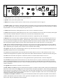
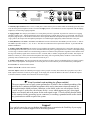
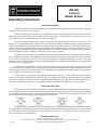
1. Main: On/off control - turns orange when on, push on/push off
2. Speaker: Turns yellow when speaker is On.
3. Blank: Remove plug to install switch for override accessory (See optional accessories on page 4).
4. Auxiliary (Line): Use this knob to control the loudness of an auxiliary line level program at the MS-200 and also throughout
the system. Typically this is a feed from an audio mixer which enables crew members, who may be far from the stage, to monitor
the performance, or as a cue feed to dressing rooms, green rooms, etc.
5. Switch: Sends the auxiliary audio signal (line level or mic. level) to outstations on circuit A.
6. Switch: Sends the auxiliary audio signal (line level or mic. level) to outstations on circuit B. Note: The auxiliary audio signal
will not be heard at the MS-200 unless it is directed to one or both of the communications circuits.
7. Auxiliary (Mic): This control serves the same function as #4 but for a signal directly from a microphone.
8. Sidetone: This recessed screwdriver-adjust potentiometer controls the loudness of your own voice heard in your own ear. It
does not affect the level heard at other stations. . Normal headset position is about 2 o’clock. When using the MS-200 with an
accessory gooseneck microphone, the sidetone adjustment should be fine-tuned to minimize feedback. This is a ‘null’ control,
that is,the position of greatest sidetone rejection will be found somewhere just on either side of the 12 O’clock position.
9. DC: This LED indicates that the MS-200 is receiving DC power from its power supply. If this lamp goes out it may indicate
that the protective circuit in the power supply has shut down. Unplug the power supply then plug it back in. If the LED does not
light, or lights then goes out quickly, check for short circuits in the inter-station cabling.
10. Signal A: The lamp in this push-button lights whenever any other station in circuit ‘A’ has its signal lamp button pressed. To
signal other stations in circuit ‘A’, press this button.
11. Circuit A: Pressing this button connects the MS-200 to the other stations in circuit ‘A’. Other stations in circuit ‘A’ may
communicate among themselves regardless of the position of this button. When the MS-200 is connected, the button turns green.
12. Link: This switch allows the operator to combine the stations on circuit B with the stations on circuit A.
13. Listen Level: This control adjusts the level of the signal heard in the operators headset, or from the loudspeaker.
14. Circuit B: This button has the same functions as #11 above but for circuit ‘B’. Circuits ‘A’ and ‘B’ are not connected together, even though both buttons are pressed in at the same time. The operator of the MS-200 may speak and listen to both circuits simultaneously, but stations on circuit ‘A’ may not communicate with stations on circuit ‘B’ and vice-versa unless the Link
switch is switched in.
15. Signal B: Same functions as #10 above, but for circuit ‘B’.
16. Mic. Switch: In the Off position, this switch permits the operator to continue to monitor either or both circuits without being
heard at the remote stations. In the Page position, the output from the microphone preamplifier is directed through a high quality
audio transformer to an output jack on the rear panel. In this way the headset microphone may be used to page through a separate
paging amplifier, eliminating the need to remove the headset to use a separate microphone. It also closes a set of normally open
contacts for switching a remote paging amplifier.
17. Headset or microphone connector: Use any good communications headset with a dynamic microphone of about 200W impedance, and earphone(s) from 8W to 400W, or with a gooseneck microphone (LSM-1 or LSM-2). Any make of 4-pin XLR connector will fit. The pin configuration is shown on page 1.