1
CONTACT INFORMATION
Website : http://www.e-daewoo.com
Call : 1-877-393-7823(1-877-DWESVC3)
Electric and Gas Dryer
DWR-WE5413WC/SC/RC
DWR-WE6413WC/SC/RC
PRODUCT FEATURES
" OUTSTANDING PERFORMANCE
Besides the large capacity, you can benefit from faster drying time, quiet
operation, and energy efficiency.
" STAINLESS STEEL DRUM
Stainless steel drum resists rust.
" DIGITAL FABRIC CARE
Multi-Level temperature control takes better care of your clothes.
" EASE OF USE
An entire selection of user-friendly functions make operating the dryer
easier.
" ONE TOUCH SELECTIONS
To choose an option, press its button once. No need to press buttons multiple times to scroll through a list
of options.
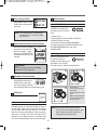
What are Sensor Dry and Time Dry?
Your dryer provides sensor drying and time drying programs.
Sensor Dry
The dryer senses the dampness of the laundry and automatically determines the heat level and operation
time. You might see a sudden increase or decrease in operation time if the sensor determines more or less
drying is required. This is not a malfunction.
Time Dry
Use TIME DRY to select heat level and drying time manually. This can be used if clothes are not as dry as
you like them at the end of the cycle. Use TIME DRY for heavy and bulky items and thick work.
A NOTE TO YOU
Thank you for purchasing a DAEWOO Dryer.
Please read this manual carefully, as it provides instructions
on safe installation, use, and maintenance
Record the model and serial numbers,and retain the manual for future reference.
For more information, please visit our website at http://www.e-daewoo.com
IMPORTANT WARRANTY AND SAFETY INSTRUCTIONS
[SEEKING WARRANTY SERVICE]
The warranty information for your dryer is located at the end of this manual. Warranty Service is available by
contacting the nearest DAEWOO
Service Center. If this product is installed and operated according to the instructions in this manual, DAEWOO will
repair or replace any parts defective in material or workmanship throughout the warranty period, beginning with the
date of purchase.
WARNING!
For your safety, the recommendations in this manual must be followed. To reduce the risk of fire or explosion,
electric shock or to prevent property damage, personal injury, or death
when using your appliance follow basic precautions
NOTE : These manual should be retained for future reference.
Warranty Restriction :
If the dryer is subjected to other than single family use, all warranty coverage is effective for only 90 days.
You will need the complete model and serial number when requesting warranty service. A proof of purchase is also
required.
Use the space below to record the model number and serial number of your new DAEWOO dryer.
Model Number
Serial Number
Date of Purchase
❈ Staple your receipt here for convenience when contacting service.
WARNING : For your safety the information in this manual must be followed to minimize the risk of fire or
explosion or to prevent property damage, personal lnjury or dearth.
- Do not store or use gasoline or other flammable vapors and llqulds in the vicinlty of this or any other appllance.
- WHAT TO DO IF YOU SMELL GAS
• Do not try to light any appliance.
• Do not touch any electrical switch; do not use any phone in your building.
• Clear the room, building or area of all occupants.
• Immediately call your gas supplier from a nel ghbor’s phone. Follow the gas supplier’s Instructions.
• If you cannot reach your gas supplier, call the fire department.
- Install ation and service must be performed by a qualified lnnstaller, service agency or the gas supplier.
FOR YOUR SAFETY
Do not store or use gasoline or other flammable vapors and liquids in the vicinity of this or any other appliance.
2
TABLE OF CONTENTS
PART 1. SPECIFICATIONS............................................................................................................................3
PART 2. INITIAL STEPS FOR INSTALLING YOUR DRYER........................................................................7
PART 3. ACCESSORIES INSTALLATION ..................................................................................................17
PART 4. ELECTRICAL REQUIREMENTS FOR ELECTRIC DRYER ........................................................18
PART 5. ELECTRICAL REQUIREMENTS FOR GAS DRYERS ................................................................24
PART 6. GAS REQUIREMENTS AND INSTRUCTIONS ............................................................................25
PART 7. USER - MAINTENANCE INSTRUCTIONS ...................................................................................26
PART 8. OPERATING YOUR DRYER .........................................................................................................28
PART 9. TROUBLESHOOTING GUIDE.......................................................................................................35
DAEWOO DRYER LIMITED WARRANTY...................................................................................................39
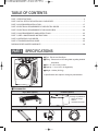
PART 1 SPECIFICATIONS
■ Type : Electric and Gas Dryer
■ Rating : Please refer to the rating label regarding detailed
information.
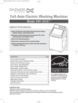
■ Size : 27 x 32.4 x 40.1 inches
■ Capacity : 7.3 cu.ft. IEC, 10.4kg(22.9lb)
■ Weight : 128 Ibs (58.5 kg)
❈ Specifications are subject to change by manufacturer.
■ Accessories
Dryer Rack (Option)
Pedestal (Option)
❈ Design of pedestals is
subject to change
without
manufacturers notice.
Skating Kit (Option)
Y Connector
3
Inlet hose
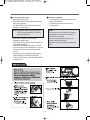
[IMPORTANT SAFETY INSTRUCTIONS]
WARNING!
To help reduce any risk of electric shock, fire, or other personal injury or property damage when using your
Appliance, please exercise care and follow basic safety precautions, including the following:
1) Read all instructions before using the appliance.
2) Do not dry articles that have been previously cleaned in, washed in, soaked in, or spotted with gasoline, drycleaning solvents, or other flammable or explosive substances, as they give off vapours that could ignite or explode.
3) Do not allow children to play on or in the appliance. Close supervision of children is necessary when the appliance
is used near children.
4) Before the appliance is removed from service or discarded, remove the door to the drying compartment.
5) Do not reach into the appliance if the drum is moving.
6) Do not install or store this appliance where it will be exposed to the weather.
7) Do not tamper with controls.
8) Do not repair or replace any part of the appliance or attempt any servicing unless specifically recommended in the
user-maintenance instructions or in published user-repair instructions that you understand and have the skills to
carry out.
9) Do not use heat to dry articles containing foam rubber or similarly textured rubber-like materials.
10) Clean lint screen before or after each load.
11) Keep area around the exhaust opening and adjacent surrounding areas free from the accumulation of lint, dust, and
dirt.
12) The interior of the appliance and exhaust duct should be cleaned periodically by qualified service personnel.
13) Do not place items exposed to cooking oils in your dryer. Items contaminated with cooking oils may contribute to a
chemical reaction that could cause a load to catch fire.
14) Do not use fabric softners or products to eliminate static unless recommended by the manufacturer of the fabric
softner or product.
15) This dryer is designed only for residential use.
16) Ensure pockets are free from small irregularly shaped hard objects, foreign material, etc. ie. coins, knives,pins, etc.
These objects could damage your dryer.
17) Do not wash clothing with large buckles, buttons, or other heavy metal or solid decorative things.
[SAVE THESE INSTRUCTIONS]
USING INSTRUCTIONS
1) Do not overload the drum, that may cause poor drying and wrinkling.
2) Do not over dry fabrics such as knitted fabrics and flannel.
3) Do not dry items such as elastic bands, plastics,rubberized items, or sneakers that might melt or ignite in the dryer.
4) Check the lint filter is in place.
5) Make sure the laundry is not caught when the door is closed to prevent fabric damage.
6) Check the filter every cycle because a clogged filter causes fire hazardous condition and affects the dryer
efficiency.
7) When cleaning the surface of the drum, you should use a non-abrasive stainless steel cleaner.
8) To prevent a short circuit or penetrating moisture, make sure the lamp cover is firmly closed.
9) Do not sit on top of the dryer.
10) Do not open the dryer door during Steam cycles. Steam can cause severe burns.
11) Do not touch the steam nozzle in the drum during or after the STEAM cycle.
NOTE: Because of continuing product improvements, Daewoo reserves the right to change specifications
without notice. For complete details, see the Installation Instructions packed with your product before
selecting cabinetry, making cutouts, or beginning installation.
4
[GROUNDING INSTRUCTIONS]
A. For a grounded, cord-connected appliance:
This appliance must be grounded. In the event of malfunction or breakdown, grounding will reduce the risk of
electric shock by providing a path of least resistance for electric current. This appliance must be equipped with a
cord having an equipment-grounding conductor and a grounding plug. The plug must be plugged into an
appropriate outlet that is properly installed and grounded in accordance with all local codes and ordinances.
WARNING!
Improper connection of the equipment grounding conductor can result in a risk of electric shock.
Check with a qualified electrician or service representative or personnel if you are in doubt as to whether the
appliance is properly grounded.
Do not modify the plug provided with the appliance. If it will not fit the outlet, have a proper outlet installed by a
qualified electrician.
B. For a permanently connected appliance:
This appliance must be connected to a grounded metal, permanent wiring system; or an equipment-grounding
conductor must be run with the circuit conductors and connected to the equipment-grounding terminal or lead on
the appliance.
5
WARNING!
To reduce the risk of fire or explosion, electric shock, property damage, personal injury or death when using this
appliance, please follow all instructions and information, including those in this manual and instructions provided
by your gas supplier.
• Do not store or use any gasoline, dry-cleaning solvents other flammable vapors or liquids in the area
surrounding this appliance.
• Do not dry anything that has or ever had anything flammable on it, even after washing.
• No washer can completely remove oil. Do not dry any articles that have or ever had any kind of oil on them,
including cooking oil.
• Articles containing foam, rubber, rubber-like materials, plastic or similar materials should be air dried.
• Failure to follow these instructions can result in fire, death or serious injury.
• A qualified service person or company must perform installation and service of this appliance.
WARNING!
• Keep flammable materials and vapors, such as gasoline, away from the dryer.
• Place dryer at least 18 inches above the floor for a garage installation.
• Failure to do so can result in death, explosion or fire.
California Safe Drinking Water and Toxic Enforcement Act
This act requires the governor of California to publish a list of substances known to the state to cause cancer, birth
defects or other reproductive harm and requires businesses to warn customers of potential exposure to such
substances.
Gas appliances can cause minor exposure to four of these substances, namely benzene, carbon monoxide,
formaldehyde and soot, caused primarily by the incomplete combustion of natural gas or LP fuels.
Properly adjusted dryers will minimize combustion. Exposure to these substances can be minimized further by
properly venting the dryer to the outdoors.
Do not allow children to play on or in the appliance. Close supervision of children is necessary when the appliance
is used near children.
6
PART 2 INITIAL STEPS FOR INSTALLING YOUR DRYER
The following instructions will guide you through the initial steps of setting up your dryer.
Please note that every section of this manual provides important information regarding the preparation and use of
your dryer, and it is important that you review this entire manual before proceeding with any installation or use.
More detailed instructions concerning electrical connections, gas connections, and exhaust requirements are
provided in other parts of this manual.
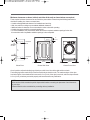
STEP 1. Positioning the Dryer.
Choose a location with a solid floor for your dryer.
Place the dryer in the desired location and make sure that it has the required clearances shown below.
44.3"
(112.5cm)
40.1"
(102.1cm)
27"
(68.6cm)
32.4"
(82.3cm)
NOTE:
• Most installations require a minimum 5
1/2(5.5)inches(14cm) clearance behind
the dryer for the exhaust vent with elbow.
• Leveling legs should be secured.
• All four legs should be stably placed on a
solid and even floor.
• If dryer is not level, laundry may not
tumble properly and sensor will not detect
humidity information accurately.
• When leveling, please be cautious not to
injure your fingers and toes.
• If you install the dryer on the optional
pedestal, it is necessary to level with the
pedestal leveling legs.
WARNING - Risk Of Fire
• Clothes dryer installation must be performed by a qualified installer.
• Install the clothes dryer according to the manufacturer’s instructions and local codes.
• Do not install a clothes dryer with flexible plastic venting materials. If flexible metal (foil type) duct is installed, it
must be of a specific type identified by the appliance manufacturer as suitable for use with clothes dryers.
Flexible venting materials are known to collapse, be easily crushed, and trap lint. These conditions will obstruct
clothes dryer airflow and increase the risk of fire.
• To reduce the risk of severe injury or death, follow all installation instructions.
• Save these instructions.
7
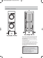
Minimum clearances on above, behind, and sides of the unit, as shown below, are required.
Those required minimum clearances are set forth in the picture below. Please keep the following instructions in
mind when installing in a closet or recessed area:
• Consider allowing additional clearance for installation and servicing.
• Wall, door and floor molding may necessitate additional clearances.
• Additional inches of clearance are recommended to reduce noise while operating.
• Consider the space needed for companion appliances.
• For closet installations, the picture below shows the minimum required ventilation openings for the door.
A louvered door with comparable ventilation openings is also acceptable.
14" max
(35.6cm)
18"
(45.72cm)
ventilation
hole
ventilation
hole
1"
(2.54cm)
Closet Door
32.4"
(82.3cm)
Closet Side View
1"
(2.54cm)
0"
(0cm)
27"
(68.6cm)
0"
(0cm)
Closet-Front View
Once in position, adjust the leveling legs of the dryer until it is level from left to right and front to back.
The leveling legs must remain firmly on the floor and the dryer should not rock. The maximum slope of the dryer
from left to right or front to back should not exceed 2.5 cm (1 inch). If the dryer is not level, and if the slope exceeds
2.5 cm (1 inch), a load may not tumble properly and internal sensors may malfunction.
NOTE:
Other sections of this manual also provide important information concerning the placement of and clearances
for your dryer.
Please review this entire manual before proceeding with any installation.
8
Installation nstructions
Open in position, adjust the leveling legs of the dryer
until it is level from left to right and front to back. Be
sure to tighten the leveling leg lock nuts against the
bottom of the dryer.
The leveling legs must remain firmly on the floor and
the dryer should not rock.
The maximum slope of the dryer from left to right or
front to back should not exceed 1”(2.5 cm). If the dryer
is not level, and if the slope exceeds 1” (2.5 cm), a
load may not tumble properly and internal sensors
may malfunction.
NOTE:
Other sections of this manual also provide
important information concerning the placement of
and clearances for your dryer.
Please review this entire manual before
proceeding with any installation.
9
STEP 2. Connecting the Exhaust System
WARNING!
• To reduce the risk of fire this appliance MUST BE EXHAUSTED OUTDOORS.
• The appliance shall not be exhausted into a chimney, a wall, a ceiling, an attic, a crawl space, or a concealed
space of a building.
• Only rigid or flexible metal duct should be used, for exhausting.
• The total length of flexible metal duct shall not exceed 2.4 m.
• Do not use plastic or thin foil duct.
• Failure to follow these instructions can result in death or fire.
• Clean old ducts before installing this dryer.
• The exhaust must be vented to the outside.
• Improper taping and incorrect installation will cause dryer malfunction.
In addition to the following warnings, please refer to manual section on Exhaust Requirements and Maintenance.
IMPORTANT: To reduce the risk of fire, combustion, and gas accumulation, the dryer must be vented to the
outdoors. Please follow the instructions (and all others in this manual) very carefully.
• Foil-type flexible ducts complied with the outline for clothes dryer transition duct, Subject UL 2158A, shall be used.
• Do not use plastic or thin foil duct.
• Use 4" (10.2 cm) diameter rigid or semi-rigid metal duct (NOTE! Venting materials are not supplied with the dryer,
and you should obtain the venting materials necessary for proper installation)
• Use the maximum duct length and number of bends refered to "USER-MAINTENANCE INSTRUCTIONS".
• Position the dryer such that the exhaust duct run is as short as possible.
• The duct shall not be assembled with screws or other fastening means that extend into the duct and catch lint.
Clean old ducts before installing this dryer
• The male end of each section of exhaust duct must point away from the dryer.
• Use as few elbow joints as possible.
• Use duct tape on all duct joints.
• Insulate ductwork that runs through unheated areas in order to reduce condensation and lint build-up on pipe
walls.
PLEASE BE AWARE THAT FAILURE TO EXHAUST THE DRYER CORRECTLY WILL VOID THE
DRYER’S WARRANTY.
Combustible materials, gasoline, and other flammable vapors and liquids must not be stored near
the dryer.
The dryer must be disconnected from the gas supply piping system during pressure testing at
pressures greater than 1/2psi(3.5kPa).
The dryer must be exhausted to the outdoors.
WHEN DISCARDING OR STORING YOUR OLD CLOTHES DRYER, REMOVE THE DOOR.
10
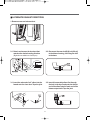
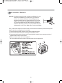
■ ALTERNATE EXHAUST DIRECTIONS
1. Remove screw and exhaust duct.
2-1. Detach and remove the knockout that
matches the desired venting direction
2-2. Reconnect the new duct[8.66 inch(22cm)]
to the blower housing, and fixing the duct
to the base.
(Right side not available on Gas Dryers)
3-1. Insert the male end of a 4" elbow into the
female end of a short duct. Tape the joint.
3-2. Insert this assembly elbow first through
the hole in the dryer and push the female
end of the elbow onto the male end of the
blower output shaft. Tape the joint.
11
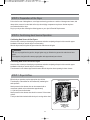
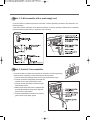
STEP 3. Connection of Gas Supply
(Gas dryer only). In addition to the following, please refer to manual section on Gas Requirements and Instructions.
1
2
5
3
4
1. New stainless steel flexible connector. Use this type of connector only if allowed by local codes. Use Design AGA
Certified Connector.
2. 1/8" NPT Pipe Plug (for checking inlet gas pressure)
3. Equipment Shut-Off Valve Installed within 6’ (1.8 m) of dryer.
4. Iron Pipe. Shorter than 20’ (6.1 m) Use 3/8" pipe. Longer than 20’ (6.1 m) - Use 1/2" pipe.
5. 3/8" N.P.T. Gas Connection.
NOTE:
Make sure the burner orifice is proper for the type of gas you have.
For instance, using LPG with LNG orifice will result in death, fire or explosion.
Or using LNG with LPG nozzle will not allow the burner to ignite.
If needed, orifice conversion should be done by a qualified service technician and mark or put the label of the
current type of orifice on the dryer.
If changing the orifice, also adjust the gas valve.
1. Confirm that the type of gas available in your laundry room is appropriate for the dryer. The dryer is prepared for
Natural Gas with a 3/8" NPT gas connector.
2. Remove the shipping cap on the gas connector at the back of the dryer. Make sure that you don’t damage the
threads of the gas connection pipe when you remove the shipping cap.
3. Connect the dryer to your laundry room’s gas supply using a new flexible stainless steel connector (as noted
below, use a new stainless steel flexible connector if allowed by your local codes).
4. Securely tighten all connections between the dryer and your laundry room’s gas supply. Turn on your laundry
room’s gas (both supply and check all pipe connections internal and external) for gas leaks with a non-corrosive
leak detection fluid.
5. For LP (Liquefied Petroleum) gas connection, refer to this manual’s section entitled Gas Requirements and
Instructions.
12
STEP 4. Electrical Plug Connections
Following steps are several warnings and instructions concerning making the electrical connection for electric
dryers.
More detailed information concerning the electrical connection is provided in the manual section entitled Electrical
Requirements for Electric Dryer.
It is important that you thoroughly review that section and the remainder of this manual, before taking any steps to
install or use this dryer.
1. Use only a new UL listed No. 10 (copper wire only) three or four conductor power supply cord kit rated 240 Volts
(minimum) 30 Amperes and labeled as suitable for use in a clothes dryer.
2. A four-wire cord is required for manufactured (mobile) home installations and where local codes do not allow
grounding of this appliance through neutral.
3. Electrical Plug Connections.
4. For additional instruction on connecting the dryer to an electrical power source, please refer to this manual's
section on Electrical Requirements and Electric Dryer.
NOTE:
Burner input requirements
If your house is located at the elevations up to 10,000 feet.
Adjusting burner input setting is not required at this elevation because AGA certifies this dryer will not have any
problem with the BTU rating at this altitude.
If your house is located above 10,000 feet, you are required to adjust a four percent (4%) reduction of the burner
BTU rating indicated on the model/serial rating plate.
WARNING!
• Use a new UL listed 30 amp power supply cord.
• Use a UL approved strain relief.
• Disconnect power before making electrical connections.
• Connect neutral wire (white or center wire) to center terminal.
• Ground wire (green or bare wire) must be connected to green ground connector.
• Securely tighten all electrical connections
• See installation instructions for complete instructions.
• Failure to do so may result in fire or electrical shock.
13
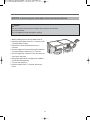
STEP 5. Preparation of the Dryer
Prior to the first use of this appliance, use all purpose cleaning products or a solution of detergent and water, with
damp cloth to remove from the inside of the dryer drum/drying compartment any dust or dirt that may have
accumulated inside the dryer.
Plug-in your dryer after reviewing the following parts on your dryer’s Electrical Requirements.
STEP 6. Confirming Heat Source Operation
Confirming Heat Source in Gas Dryers
Close the door to the dryer drum/drying compartment and, after completing all steps in this manual for proper
installation of this dryer, start the dryer on a heat setting.
After the dryer starts, the igniter will glow red and the main burner will ignite.
WARNING!
If all air is not purged from the gas line, the gas igniter may go off before the gas and the main burner have
ignited.
If this happens, the igniter will re-attempt gas ignition after approximately two minutes.
Confirming Heat Source in Electric Dryers
Close the door to the dryer drum/drying compartment and, after completing all steps in this manual for proper
installation of this dryer, start the dryer on a heat setting.
The exhaust air or the exhaust pipe should be warm after the dryer has been operating for three minutes.
STEP 7. Dryer Airflow
Effective dryer operation requires appropriate dryer airflow.
The adequacy of the airflow can be measured by evaluating the
static pressure.
Static pressure in the exhaust duct can be measured with a
manometer, placed on the exhaust duct approximately
1 ft. (30.5cm) from the final outlet.
Static pressure in the exhaust duct should not exceed 7.6mm water
column.
The dryer should be checked while the dryer is running with no load.
Measuring Static pressure
Manometer
Exhaust Duct
MAXIMUM STATIC
PRESSURE IN
WATER COLUMN
7.6mm
14
STEP 8. Procedure for Reversing the Door
The door on your dryer can be installed to open either to the left or the right. Follow these instructions to reverse the
direction in which your door opens:
Note : Door and latch should be aligned at the center when closed.
STEP 9. Additional Instructions for Installation of Your Dryer in a Manufactured or Mobile Home.
The following instructions are applicable to installations of the dryer in a manufactured or mobile home.
Any installation in a manufactured or mobile home must comply with the Manufactured Home Construction and
Safety Standards Title 24 CFR, Part 32-80 or Standard CAN/CSA0Z240 MH and local codes and ordinances.
If you are uncertain whether your proposed installation will comply with these standards, please contact a service
and installation professional for assistance. (CONTACT INFORMATION : 1-877-393-7823(1-877-DWESVC3)
The following instructions apply to any installation of the dryer in a manufactured or mobile home:
1) The electrical connection for an electric dryer must be a 4-wire connection. More detailed information concerning
the electrical connection is provided at the manual section entitled Electrical Requirements for Electric Dryer
2) To reduce the risk of combustion and fire, the dryer must be vented to the outside.
3) Electric dryers may be vented to the outside using the back, left, right, or bottom panel.
4) Gas dryers may be vented to the outside using the back, left, or bottom panel. Gas dryers must not be vented to
the outside using the right side panel because of the burner housing.
5) The dryer exhaust duct must be affixed securely to the manufactured or mobile home structure, the exhaust duct
must be made of a material that will resist fire and combustion, and it is recommended that you use a rigid or
flexible metal pipe.
6) DO NOT connect the exhaust duct with any other exhaust duct, vent, or chimney.
7) Make sure the dryer has adequate access to outside fresh air to ensure proper operation.
The opening for outside fresh air must be at least 25 in2 (163 cm2).
8) It is important that the clearance of the duct from any combustible construction be at least 2 inches (5 cm), and,
when venting the dryer to the outdoors, the dryer can be installed with a clearance of 1 inch at the sides and back
of the dryer.
9) Please be aware that venting materials are not supplied with the dryer.
You should obtain the venting materials necessary for proper installation.
WARNING!
DO NOT connect exhaust ducts with metal screws or fasteners that extend into the duct.
DO NOT vent the exhaust duct under the manufactured or mobile home.
15
STEP10. Connecting the inlet water hose for steam features
Caution!
The dryer must be connected to the cold water faucet using the new inlet hose.
Do not use old hoses
Do not overtighten, as it may damage the coupling.
1. Before installing dryer turn the cold water faucet off.
2. Attach the brass female end of the “Y” connector to the
cold water wahser fi ll valve.
3. Connect the hose to cold waher faucet and “Y”
connector
4. Connect straight end of hose which supplied with dryer
accessory package to other end of “Y” connector
5. Connect angled end of hoses to fi ll the valve at the top
of the dryer’s rear frame.
6. Using pliers, tighten all the coupling with an additional
2/3 turn after hand tightening.
7. Turn the water faucets on.
8. Check for leaks around “Y” connector, faucets and
hoses.
16
PART 3 ACCESSORIES INSTALLATION
Stacking Kit Installation Instructions(DRYER & PEDESTAL)
To ensure safe and secure installation, please observe the instructions below.
WARNING!
Incorrect Installation can cause serious accidents.
The weight of the dryer and the height of installation makes the stacking procedure too risky for one person.
This procedure should be performed by 2 or more experienced service personnel.
1) Remove pedestal, installation hardware, and instructions are in the shipping carton.
2) Position dryer on top of the pedestal.
NOTE:
Because of the weight of the dryer two or more people may be needed.
If dryer was previously installed, uninstall it as follows
Refer to pedestal installation manual.(Pedestal Model : P-W151)
A : Uninstalling an electric dryer:
1 Unplug the power supply cord,
2 Pull the dryer away from the wall enough to loosen
the vent clamp.
Loosen the clamp and carefully remove the exhaust
vent from the dryer exhaust outlet.
B : Uninstalling a gas dryer:
1 Shut off gas.
2 Unplug power cord.
3 Disconnect gas line from dryer.
4 Pull away and loosen vent clamp.
5 Disconnect venting.
17
PART 4 ELECTRICAL REQUIREMENTS FOR ELECTRIC DRYERS
The following are additional instructions regarding electrical connections and requirements for electric dryers.
Important Warning
To help prevent fire, electric shock, serious injury or death, the wiring and grounding must conform to the latest
edition of the National Electrical Code, ANSI/NFPA 70 and all applicable local regulations.
Please contact a qualified electrician to check your home’s wiring and fuses to ensure that your home has
adequate electrical power to operate the dryer.
120V/ 240V, 60 Hertz, 3-Wire Installation
Instructions for Grounding of your Electric Dryer:
a) This dryer must be connected to a grounded metal, permanent wiring system or an equipment-grounding
conductor must be run with the circuit conductors and connected to the equipment-grounding terminal or
lead on the dryer.
b) The dryer has its own terminal block that must be connected to a separate 60 Hertz single phase AC
circuit, fused at 30 Amperes
(the circuit must be fused on both sides of the line).
ELECTRICAL SERVICE FOR THE DRYER SHOULD BE OF MAXIMUM RATE VOLTAGE LISTED ON
THE NAMEPLATE.
DO NOT CONNECT DRYER TO 110, 115, OR 120 VOLT CIRCUIT.
c) If branch circuit to dryer is fifteen feet (4.50 m) or less in length, use U.L. (Underwriters Laboratories) listed
No. 10 A.W.G. wire (copper wire only), or as required by local codes.
If over fifteen feet (4.50 m), use U.L. (Underwriters Laboratories) listed No. 8 A.W.G. wire (copper wire
only), or as required by local codes.
Allow sufficient slack in wiring so dryer can be moved from its normal location when necessary.
d) The power cord (pigtail) connection between wall receptacle and dryer terminal block IS NOT supplied with
dryer.
Type of pigtail and gauge of wire must conform to local codes and with instructions mentioned on the
following pages.
e) The method of wiring the dryer is optional and subject to local code requirements. Refer to examples on
next page.
f) You must select the method by which to wire your dryer according to local code and ordinance
requirements.
Sample methods are included in the following pages.
18
Review the following options to determine the appropriate electrical connection for your home:
Use the instructions in this section if your home has a
4-wire receptacle (NEMA type 14-30R) and you will be
using a UL listed, 120/240 volt minimum, 30 amp,
dryer power supply cord.
Use the instructions in this section if your home has a
3-wire receptacle (NEMA type 10-30R) and you will be
using a UL listed, 120/240 volt minimum, 30 amp,
dryer power supply cord.
4-wire receptacle
(NEMA type14-30R)
3-wire receptacle
(NEMA type10-30R)
If this type is available at your home. you will be
connecting to a fused disconnect or circuit breaker
box.
If this type is available at your home. you will be
connecting to a fused disconnect or circuit breaker
box.
3-wire direct
4-wire direct
19
4-wire connection : Direct wire
Important : Grounding through the neutral conductor is prohibited for (1) new
branch-circuit installations, (2) mobile homes, (3) recreational
vehicles, and (4) areas where local codes prohibit grounding
through the neutral conductor. Prepare minimum 5 ft (1.52 m) of
length in order for dryer to be replaced. First, peel 5 inches (12.7
cm) of covering material from end. Strip 5 inches of ground wire
insulation. After cutting 11/2 inch (3.8 cm) from 3 other wires peel
insulation back 1 inch (2.5 cm). Make ends of 3 wires a hook shape.
Then, put the hooked shape end of the wire under the screw of the terminal block (hooked end facing to the
right) and pinch the hook together and screw tightly.
1. Connect neutral wire (white) of power cord to center terminal block screw.
2. Connect red and black wires to the left and right terminal block screws.
3. Connect ground wire (green) of power cord to external ground screw and move neutral ground wire of
appliance and connect it to center screw.
4. Make sure that the strain relief screw is tightened.
Be sure that all terminal block nuts are on tight and power cord is in right position.
20
3-wire connection : Direct wire
Important : Grounding through the neutral conductor is prohibited for (1) new
branch-circuit installations, (2) mobile homes, (3) recreational
vehicles, and (4) areas where local codes prohibit grounding through
the neutral conductor. Prepare minimum 5 ft (1.52 m) of length in
order for dryer to be replaced. First, strip 3 1/2 inches (8.9 cm) of
outer sheath from end and strip 1 inch of insulation from each
conductor.
Then, put the hooked shape end of the wire under the screw of the terminal block (hooked end facing rightward)
and pinch the hook together and tighten the screw securely.
1. Connect neutral wire (white) of power cord to center terminal block screw.
2. Connect red and black wires to the left and right terminal block screws.
3. Make sure that the strain relief screw is tightened.
Be sure that all terminal block nuts are on tight and power cord is in right position.
21
Option 1: 4-wire connection with a power supply cord.
• lf your local codes or ordinances do not allow the use of a 3-wire connection, or you are installing your dryer in
a mobile home, you must use a 4-wire connection.
1. Connect neutral wire (white) of power cord to center terminal block screw.
2. Connect red and black wires to the left and right terminal block screws.
3. Connect ground wire (green) of power cord to external ground screw and move neutral ground
wire of appliance and connect it to center screw.
4. Make sure that the strain relief screw is tightened.
Be sure that all terminal block nuts are on tight and power cord is in right position.
22
Option 2: 3-Wire connection with a power supply cord.
lf your local codes or ordinances permit the connection of a frame-grounding conductor to the neutral wire, use
these instructions.
If your local codes or ordinances do not allow the connection of a frame-grounding conductor to the neutral wire,
use the instructions under Section 1: Optional 3- wire connection.
Section 1
Option 3: Optional 3-wire connection.
• If your local codes or ordinances do not allow the connection of a frame-grounding
conductor to the neutral wire, use the instructions under this section.
1. Connect neutral wire (white) of power cord to center terminal block screw.
2. Connect ground wire of appliance and neutral wire
of power cord to center terminal block screw.
3. Connect red and black wires to the left and right
terminal block screws.
4. Make sure the strain relief screw is tightened. Be
sure that all terminal block nuts are on tight and
power cord is in right position.
5. Connect independent ground wire from external
ground connector to proper ground.
23
PART 5 ELECTRICAL REQUIREMENTS FOR GAS DRYERS
120 Volt, 60 Hertz, with 3-Prong Grounding Plug
Following are additional instructions regarding electrical connections and requirements for gas dryers.
Important Warning
To help prevent fire, electric shock, serious injury or death, the wiring and grounding must conform to the
latest edition of the National Electrical Code, ANSI/NFPA 70, or the Canadian Electrical Code, CSA C22.1,
and all applicable local regulations. Please contact a qualified electrician to check your home’s wiring and
fuses to ensure that your home has adequate electrical power to operate the dryer.
Electrical Requirements for Your Dryer:
a) Please note that the wiring diagram is provided inside the dryer control hood. Label all wires prior to disconnection
when servicing the dryer, because wiring errors can cause serious injury to you and your dryer.
b) Your dryer is designed to be used on a separate branch, polarized, three-wire, effectively grounded, 120 Volt, 60
Hertz, AC (alternating current) circuit protected by a 15 Ampere fuse, equivalent fuse or circuit breaker.
c) Use separately fused circuits for washers and dryers, and DO NOT operate a washer and a dryer on the same
circuit.
WARNING!
Do not overload the circuit by operating other appliances on the same circuit when this appliance is
operating, by using an extension cord to connect the dryer to the power source, or by using any adapter to
allow additional cords to connect to the same outlet.
WARNING!
DO NOT modify the plug provided with the dryer. If it does not fit the outlet in your laundry room, a proper
outlet will need to be installed in your laundry room by a qualified service person or company.
STANDARD 120 VOLT, 60 HERTZ, 3-WIRE EFFECTIVELY
GROUNDED CIRCUIT
1 L1
2 Ground
3 Neutral Side
4 Round Grounding Prong
5 Neutral
a) The dryer has a three-prong plug to help guard against shock. The plug should be plugged directed into a properly
grounded three-prong receptacle that is rated 120 Volts AC (alternating current) 15 Amps. This plug, in order to be
properly and fully effective, must be plugged into a properly installed outlet that is grounded in accordance with all
local codes and ordinances.
b) The dryer must be grounded in order to reduce the risk of electric shock, including a malfunction or breakdown.
c) If your laundry room does not meet the specifications required by this manual, or if you are uncertain whether or not
your laundry room meets these specifications, please have a qualified service person or company.
Review your laundry room’s electrical supply for any problems.
24
PART 6 GAS REQUIREMENTS AND INSTRUCTIONS
Following are important instructions and information concerning the requirements for the gas supply and service for
gas dryers.
Important Warning
The gas supply and service for a gas dryer must comply with all local codes and ordinances.
In the absence of any local codes or ordinances in your area, the gas supply and service for your gas dryer
must comply with the latest edition of the National Fuel Gas Code, ANSI Z223.1/NFPA 54.
1. Gas supply requirements: Liquefied Petroleum (L.P.) Gas (2,500 Btu/ft3 (93.1 MJ/m3)) service must be provided
at 10 + 1.5 in. water column pressure.
2. A qualified technician must perform the LP gas coversion.
Contact your local gas service branch if you require additional assistance or information.
3. Isolate the dryer from the gas supply piping system by closing its individual manual shut-off valve during any
pressure testing of the gas supply system at test pressure equal to or less than 2/1 psi (3.45 kPa).
4. Supply Line Requirements. Your laundry room must have a rigid gas supply line to your dryer.
In the United States, an individual manual shutoff valve MUST be installed within at least 6 feet (1.8 m) of the
dryer, in accordance with the National Fuel Gas Code ANSI Z223.1. A 1/8 in. N.P.T. pipe plug must be installed
as shown.
WARNING!
DO NOT attempt any disassembly of the dryer. Any disassembly requires the attention and tools of an
authorized and qualified service person or company.
5. If using a rigid pipe, the rigid pipe should be 1/2 inch IPS. If acceptable under local codes and ordinances and
when acceptable to your gas supplier, 3/8 inch approved tubing may be used where lengths are less than 20 feet
(6.1 m). Larger tubing should be used for lengths in excess of 20 feet (6.1 m). It is also important that you use
pipe joint compound that is insoluble in LP gas.
6. To reduce the danger of gas leaks, explosion, and fire, please follow and observe the following instructions and
WARNINGS.
• Connect the dryer to the type of gas shown on the nameplate.
• Use new flexible stainless steel connectors.
• Use Teflon tape and pipe joint compound insoluble in LP gas on all pipe threads.
• Purge gas supply of air and sediment before connecting the gas supply to the dryer in order to prevent gas
valve contamination. Before tightening connection between gas supply and dryer, purge remaining air until odor
of gas is identified.
• DO NOT use an open flame to inspect for gas leaks; instead use a non-corrosive leak detection fluid
WARNING!
• Use a new AGA or CSA approved gas supply line.
• Install a shut-off valve.
• Securely tighten all gas connections.
• If connected to LP, have a qualified person make sure gas pressure does not exceed 13 in. water column.
• Examples of a qualified person include licensed heating personnel, authorized gas company personnel, and
authorized service personnel.
• Failure to do so can result in death, explosion, or fire.
25
PART 7 USER-MAINTENANCE INSTRUCTIONS
Following are important instructions and information concerning the exhaust requirements for your dryer.
Important Warning
To reduce the risk of fire, electric shock, or injury to person, read the IMPORTANT SAFETY INSTRUCTIONS before
operating this appliance. To reduce the risk of fire, combustion, or accumulation of combustible gases, DO NOT
exhaust dryer air into an enclosed and unventilated area, such as an attic, wall, ceiling, crawl space, chimney, gas vent,
or concealed space of a building. To reduce the risk of fire, DO NOT exhaust the dryer with plastic or thin foil ducting.
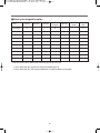
Weather Hood
Type
Recommended
Use Only for Short RunInstallations
Maximum length of 4”
Number of
(10.2 cm) diameter rigid
90° Elbows
metal duct
Maximum length of 4”
(10.2 cm) diameter
flexible metal duct
0
65 feet (19.8 m)
45 feet (13.7 m)
1
55 feet (16.8 m)
35 feet (10.7 m)
2
47 feet (14.3 m)
30 feet (9.1 m)
3
36 feet (11.0 m)
25 feet (7.6 m)
4
28 feet (8.5 m)
20 feet (6.1 m)
0
55 feet (16.8 m)
35 feet (10.7 m)
1
47 feet (14.3 m)
27 feet (8.2 m)
2
41 feet (12.5 m)
21 feet (6.4 m)
3
30 feet (9.1 m)
17 feet (5.2 m)
4
22 feet (6.7 m)
15 feet (4.5m)
NOTE: Deduct 6 feet (1.8 m) for each additional elbow. It is not recommended to use more than 4 90° elbows.
Exhaust Requirements and Instructions:
1. Venting materials are not provided with the dryer and you should obtain the necessary venting materials.
For example, the outer end of exhaust pipe must have a weather hood with hinged dampers to prevent backdraft when the dryer is not in use.
2. The exhaust duct must be four inches (10.2 cm) in diameter with no obstructions. The exhaust duct should be
kept as short as possible. Make sure to clean any old ducts before installing your new dryer.
3. Rigid or semi-rigid metal ducting is recommended for use as transition ducting between the dryer and and the
wall. In special installations when it is impossible to make a connection with the above recommendations, then a
UL-listed flexible metal transition duct may be used between the dryer and wall connection only.
The use of this ducting will affect dry time.
4. DO NOT use sheet metal screws on exhaust pipe joints or other fastening means which extend into the duct that
could catch lint and reduce the efficiency of the exhaust system. Secure all joints with duct tape.
5. To maximize operating results, please observe the duct length limitations noted in the chart above.
26
Exhaust and Dryer Maintenance
WARNING!
Disconnect the dryer’s electric power prior to any cleaning or maintenance.
1. After one year of use, the interior and complete exhaust system of the dryer should be examined and cleaned if
necessary.
2. Before one year of use, when drying performance has become unsatisfactory, please examine and clean the
exhaust duct for better drying performance.
3. Check the weather hoods frequently to ensure the dampers are moving freely, that the dampers are not pushed
in and that nothing has been set against the dampers.
4. A qualified service person or company should be used to perform this maintenance.
5. A Flexible Metal Vent Kit, sold separately, can be used to exhaust the dryer when it is placed in hard to reach
location. This Kit comes in two pieces, one to attach on the dryer and the other to attach on the wall exhaust
outlet. After attaching two separate pieces to the dryer and the wall, the dryer may be returned to its final
position, after which the two pieces themselves can be connected.
6. Ordinarily, the dryer drum will need no care. Wipe the exterior of the dryer as required, and always wipe the
exterior of the dryer in the event any detergent, bleach, or other washing products is spilled on the dryer.
7. Clean the control panel with a damp cloth as necessary. Warning: spray pre-wash products may damage the
finish of the control panel.
8. Please clean the lint filter either before drying each load or after drying each load.
9. Always make sure the lint filter is clean before starting a new load, because a clogged lint filter may increase
drying times.
10. Annually remove the lint filter and attach it to the vacuum duct. See item #2 above.
11. Please note that the wiring diagram is provided inside the dryer control hood. Label all wires prior to
disconnection when servicing the dryer, because wiring errors can cause serious injury to you and your dryer.
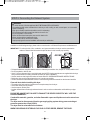
Cleaning the Lint Screen
1. Clean the lint filter once either before or after drying each load. Always make sure the lint filter is clean before
starting a new load, because a clogged lint filter may increase drying times.
2. To clean, pull the lint screen straight up and roll any lint off the screen with your fingers.
Do not rinse or wash screen to remove lint. Push the lint screen firmly back into place.
3. Always ensure the lint screen is firmly secured before running the dryer. Running the dryer with a loose lint
screen may cause overheating and damage to the dryer and articles being dried.
4. Some articles may shed more lint than others, causing the lint screen to fill rapidly.
Remove lint from the lint screen before and after drying these articles, such as new towels.
5. In the event lint falls off of the lint screen and into the dryer during removal, inspect the exhaust hood and
remove any lint.
6. Laundry detergent and fabric softener residue can build up on the lint screen, causing longer drying times.
The screen is likely blocked if lint falls off the screen. In order to prevent this type of build up, and help ensure
proper operation of your dryer, clean the lint screen with a nylon brush every six months or more frequently, if
necessary. The lint filter can also be washed as follows:
a) After rolling the lint off of the screen with your fingers, wet both sides of the screen with hot or warm water.
b) Wet a nylon brush with hot water and liquid detergent and scrub the lint screen with the brush to remove the
buildup of detergent and fabric softener.
c) After the residue has been removed, rinse screen with hot water.
d) After drying the lint screen with a clean towel, firmly replace the lint screen in your dryer.
27
PART 8 OPERATING YOUR DRYER
Following are instructions for starting and using your new dryer. Please refer to specific sections of this manual for
more detailed information.
Important Warning: To reduce the risk of fire, electric shock, or injury to person, read this entire manual, including
the Important Safety Instructions. before operating this dryer.
4 Status, Check Filter,
Drying, Cooling
3 Time Change
Button
8 Drying Time
Control
2 Cycle Selection
More Time
Normal
Speed Dry
Very dry
More dry
Normal
Towels
Delicate
Less dry
Damp dry
Air Dry
Bulky/Large
Iron Dry
High
Mid high
Medium
Perm Press
Gym Shoes
Low
Ultra low
1 Power Button
PROCESS
EST. TIME REMAINING
Less Time
Rack Dry
High
Anti-Crease
Low
Reduce Static
Off
w Start/Pause
9 Temp.
Control
0 Dryness
Intensity
Control
60min
50min
40min
30min
20min
6 Child Lock
q Beeper
5 Est. Time
Remaning
7 Option Buttons
WARNING!
Fire Hazard
No washer can completely remove oil. Do not dry anything that has ever had any type of oil on it (including
cooking oils). Items containing foam, rubber, or plastic must be air dried. Failure to follow these instructions can
result in death or fire.
WARNING!
Explosion Hazard
Keep flammable materials and vapors, such as gasoline, away from dryer.
Do not dry anything that has ever had anything flammable on it (even after washing). Failure to follow these
instructions can result in death, explosion, or fire.
28
■ Select cycles designed for option
Level
Time Dry
MoreTime
LessTime
Custom
Program
Rack Dry
Anti
Crease
damp dry
beep
Perm Press
O
O
O
Bulky
O
O
O
Delicate
O
O
O
Towel
O
O
O
O
O
Normal
O
O
O
O
O
Speed Dry
O
O
O
O
O
O
O
O
O
O
O
O
O
Steam Spray
Air Dry
O
O
O
Iron dry
Gym Shoes
O
O
O
* When the course is set on reduce static, the cooling time will turn to 30 sec.
A. If you select Rack Dry, the previous course and operation goes off.
B. If you select Rack Dry, Anti Crease, Anti-Bacterial, or Damp-Dry-Beep is not available.
29
O
O
O
O
O
O
1 Power Button
Speed Dry
Use for small loads or loads that need less drying
time.
Air Dry
Use the Air Dry Modifier for items that require drying
without heat such as rubber, plastic and heatsensitive
fabrics.
Steam Spray
Use this cycle to remove wrinkles from items, such as
clothes packed in a suitcase or items wrinkled from
being left in the dryer too long.
• Use this button for power on or off.
2 Cycle Selection
• Turn the knob to select the desired cycle based
on laundry types and conditions.
(1) Sensor Dry Cycles
Sensor Dry Cycles allow you to match the cycle to the
load you are drying. Each cycle dries certain fabrics at
the recommended temperature.
A sensor detects the moisture in the load and
automatically adjusts the drying time for optimal
drying
NOTE: Steam Spray Functions
• Do not use Steam Spray with item such as wool,
blankets, leather jackets, silk, wet clothes,
lingerie, foam products.
• For best results, load articles of similar size ans
fabric type. Do not overload, (Max. 5 Standard
dress shirts: 2.2 lb.) *shirt : 60~70% cotton /
30~40% poly-blend.
• When the filter/duct is clogged, the Steam option
may not have optimal results.
• When the Steam function is operating, the durm
will stop to allow steam to stay in the drum.
Bulky/Large
Use for drying heavy fabrics such as quilts and
blankets.
Towels
Use for drying denims, towels, heavy cottons.
Normal
Use for drying sturdy fabrics such as casual clothes.
Perm. Press
Use for permanent pressed and synthetic items.
Delicates
Use for drying synthetic fabrics, washable knit fabrics
and no-iron finishes.
Iron Dry
The IRON DRY provides uniform, properly dampened
fabrics for ironing, which can save time and make
ironing easier.
Sensor Dry Preset Cycle Settings
Sensor Dry
Cycles Load Type
Temp.
Time*
(Minutes)
BULKY/LARGE
Bulky, heavy weight
High
55
TOWELS
Towel, denim pants
MID
High
59
Medium
47
PERM, PRESS
Synthetics, permanent press
Low
40
DELICATES
Lingerie, sheets, blouses
Low
35
NORMAL
Work clothes, corduroys
Caution!
• Do not open the dryer door during steam cycles.
Steam can cause severe burns.
• Do not touch the steam nozzle in the drum
during or after the STEAM cycle.
Gym shoes
Use this in drying running shoes. Gym shoes are dried
by using rack dry. Running shoes come in three types.
(running shoes, sports shoes, sneakers and trainers)
Manual Preset Cycle Settings
Manual Dry
Sycles Load
(2) Manual Dry Cycles
Use Manual Cycles to select a specific amount of
drying time and a drying temperature.
When a Manual Cycle is selected, the ESTIMATED
TIME REMAINING display shows the actual time
remaining in your cycle. You can change the actual
time in the cycle by pressing MORE TIME or LESS
TIME.
SPEED DRY
SMALL LOADS
Tamp.
Default Time*
(Mlnutes)
High
30
Steam Spray
Remove Wrinkles
AIR DRY
Air Dry
35
Iron Dry
-
15
Medium
90
Gym Shoes
30
17
Mist
More Time
Less Time
3 Time Change Button
7 Option Buttons
More Time
• Press MORE TIME or LESS
TIME until the desired drying
time is set.
(1) CUSTOM PROGRAM
Less Time
Set up your favorite
combination of settings and
save them here for one touch
recall.
NOTE: Time change button is available only
with Manual Dry, Time Dry and Rack
Dry programs.
Rack Dry
4 Status/Clean Filter/Anti Crease Indicator
• When Anti Crease is selected,
the light for Anti Crease will
glow in the display. When
power is on, CHECK FILTER
is displayed until start/pause is
selected.
More Time
1. Select a cycle.
Rack Dry
2. Change DRY LEVEL and TEMP. CONTROL.
Less Time
3. Select OPTIONS you want.
4. Press and hold the CUSTOM PROGRAM.
More Time
To recall your stored CUSTOM PROGRAM
Press
Anti-Crease
CUSTOM PROGRAM
button,
Less
Time then press
START/PAUSE.
PROCESS
Anti-Crease
EST. TIME REMAINING
(2) Rack Dry
Rack Dry
Reduce Static
Mist
Reduce Static
Rack Dry is designedAnti-Crease
to use
for items which are not
Rack Dry
Reduce Static
suitable for tumble drying such
as sweaters, silk or lingerie.
This option may be used for drying Sneakers.
w
WARNING!
For better drying performance and safety,
clean lint filter every single use.
Anti-Crease
1
2
More Time
Reduce
Static
Less
Time
5 Estimated Time Remaining
• The display shows the
EST. TIME REMAINING
estimated time remaining. In
addition to this, if the dryer
has some problem, it displays
error messages. Refer to troubleshooting guide
More Time
1. Open the door.
Less3Time Hold the dryer rack with
both hands.
2. Put the dryer rack into the
drum.
3. Make sure Dryer RACK is
evenly spaced right onto
the drum inside. Rack Dry
6 Child Lock
(1) Child Lock
Child Lock can be used to prevent children from
changing options on control panel while the dryer is
running. When Child Lock is enabled, all the buttons
will be locked and Child Lock will glow. To enable
Child Lock, Press and hold Beeper Dry for 3 seconds,
until there is a single beep tone and Child Lock is
displayed on the status window. To disable Child
Lock, press and hold Beeper Dry for 3 seconds again.
NOTE: Don’t use the rack for normal tumble Anti-Crease
Rack Dry
drying. The rack is shipped in place in your
dryer. Please remove the rack before
using this dryer for the first time.
Anti-Crease
31
Reduce Static
Reduce Static
Rack Dry
Anti-Crease
Mist
Reduce Static
(5) Damp Dry Beep
Suggested Items Temperature Suggested
for Rack Drying Setting
Time*
(Minutes)
When you select the damp
dry beep option, a beep will
alert you when your load is
just damp enough for ironing or pressing.
This notice will allow you to remove lightweight items
that are dried or other items that you may wish to iron.
More Time
Washable wool items
Low
20
Less Time
Stuffed toys with
cotton or polyester
fiber filling
Low/Ultra
Low
20/30
Stuffed toys, foam
rubber filled.
Air Dry/
Ultra Low
50/30
Foam rubber pillows
Air Dry More50Time
Athletic shoes
Air Dry Less20
Time
8 Time Dry
60min
50min
40min
30min
20min
• Use Time Dry Option to
change Drying Time on
your own.
You can select the desired operation time
manually by pressing Time Dry button between
20 to 60 minutes.
* Reset time as needed to complete drying.
Rack Dry
3) Anti Crease
This option helps to prevent
Anti-Crease
wrinkles on your laundry.
When you select the Anti
Crease option, the dryer will periodically tumble for up
to three hours after
Reduce
Rack
DryStatic
the cycle has completed.
You can use this option in case you can not remove
laundry immediately after drying is done.
Damp dry
9 Temp. Control
High
Mid high
Medium
• Use Temp. Control
Option to select
Low
Ultra low
temperatures for the
Manual Cycles. Press TEMP. CONTROL until
the desired temperature setting glows.
Temperature modifiers cannot be used with the
Sensor Dry Cycles.
Anti-Crease
4) Reduce Static
When Using Air Dry
This option injects steam late
in the drying cycle to reduce
Reduce Static
the static electricity caused by
dry fabrics rubbing together.
Anti Static Will be able to use independently, will be
able to apply in course. Application the course which
is possible Normal, Towel, Bulky, Delicate, Perm
Press.
This chart shows examples of items that can be dried
using AIR DRY.
Type of Load
Caution!
• Do not open the dryer door during steam cycles.
Steam can cause severe burns.
• Do not touch the steam nozzle in the drum
during or after the STEAM cycle.
Default Time*
(Minutes)
Foam rubber-pillows,
padded bras, stuffed toys
20 - 30
Plastic shower curtains,
tablecloths
20 - 30
Rubber-backed rugs
40 - 50
Olefin, polypropylene,
shear nylon
10 - 20
* Reset cycle to complete drying, if needed.
32
• Check to see that coverings are securely stitched.
• Shake and fluff pillows by hand periodically during
the cycle.
• Dry item completely. Foam rubber pillows are slow
to dry.
Starting your dryer
1 Before use
• Clean lint screen before or after each cycle.
• Place laundry into dryer and shut door. See
Loading.
• Turn the knob to select the drying cycle you want.
The preset setting for Sensor Dry Cycles or Manual
Cycles will glow. The estimated or actual cycle time
(in minutes) will show in the display.
NOTE: DRY LEVEL selections can only be made
while using Sensor Dry Cycles.
Selecting MORE Dry or LESS Dry
automatically adjusts the needed time
which is already sensed.
Following are sample loads for Super Capacity
Dryers:
10 Dry Level
Very dry
More dry
Normal
• Use these buttons to set
Less dry
dry level
Damp dry
• First, select sensor dry
cycle.
• Select dry level to adjust how much you want to
dry the load.As the cycle runs, the control senses
the dryness of the load and adjusts the time
automatically based on the selected dryness
level.
NOTE: DRY LEVEL selections can only be made
while using Sensor Dry Cycles.
Selecting MORE Dry or LESS Dry
automatically adjusts the needed time
which is already sensed.
11 Beeper
Heavy Work Clothes
4 jeans
4 work pants
4 work shirts
2 sweatpantsMist
2 sweatshirts
Cotton/Towels
10 bath towels
10 hand towels
14 wash cloths
Mixed Load
3 sheets
4 pillow cases
3 shirts
3 blouses
9 T-shirts
9 Shorts
10 handkerchiefs
More Time
Less Time
Rack Dry
2 Loading
• Determine load size by the amount of space the
load requiresMore
ratherTime
than the weight of the load.
• Avoid overloading the dryer.
Less
Time can help reduce
Following these
instructions
your utility bill, prolong the life of your clothes,
and decrease the likelihood of uneven drying
and wrinkle.
High
• The BEEPER controls
Low
the volume of the beep
Off
that is made when you
press any of the buttons on the control panel.
Press BEEPER to adjust the sound level or turn
off the signal.
Anti-Crease
Reduce Sta
3 To use a sensor dry cycle
• Select DRY LEVEL to adjust how dry you want
the load. As the cycle runs, the control senses
the dryness of the load and adjusts the time
automatically for the selected dryness level.
Rack options.
Dry
• Select the desired
• Press START/PAUSE
12 Start / Pause Button
NOTE: DRY LEVEL selections can only be made
Anti-Crease
while using
Sensor Dry Cycles. Selecting
MORE Dry or LESS Dry automatically
adjusts the sensed time needed.
• Use this button for start or pause.
33
Reduce Static
Mis
4 To use a manual dry cycle
5 Pausing or restarting
• Select a Manual Dry Cycle.
• Press MORE TIME or LESS TIME until the desired
drying time is displayed.
Tap MORE TIME or LESS TIME and the time will
change by 1 minute interval.
• To pause the dryer at any time:Open the door or
press START/PAUSE.
• To restart the dryer Close the door. Press
START/PAUSE.
NOTE: The MORE TIME or LESS TIME feature
can be used with Manual Dry, Time Dry
and Rack Dry Cycles.
NOTE:
Drying will continue from where the cycle was
interrupted if you close the door and press
START within 10 minutes.
If the cycle is interrupted for more than 10
minutes, the dryer will shut off.
Select new cycle settings before restarting the
dryer.
• Press TEMP. CONTROL until the desired
temperature indicator glows.
• (OPTIONAL STEP) If desired, select OPTIONS. For
more details, see Options.
• Press START/PAUSE. Be sure the door is closed.
• If you do not press START/PAUSE within 10 minutes
of selecting the cycle, the dryer will automatically
shut off.
• If you wish to end your drying cycle after pressing
START/PAUSE, press START/PAUSE again.
To stop your dryer at any time Press START/PAUSE
or open the door.
1
2
3
34
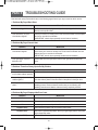
PART 9 TROUBLESHOOTING GUIDE
Save time and money! Review the charts on the following pages first and you may not need to call for service.
1. Problem: My Dryer Won’t Start
Question
What to Do
• Is the dryer plugged in?
Confirm that the dryer’s plug is securely and completely pushed into the
laundry room’s power outlet.
• Is the fuse blown, or is the
circuit breaker tripped?
Check your home’s or laundry room’s fuse box/circuit breaker box and replace
the fuse or reset the circuit breaker.
(IMPORTANT: electric dryers generally use two fuses or breakers.)
2. Problem: My Dryer Doesn’t Heat
Question
What to Do
• Is the fuse blown, or is the
circuit breaker tripped?
If the fuse is blown or the circuit breaker tripped, the dryer might tumble but not
heat. Check your home’s or laundry room’s fuse box/circuit breaker box and
replace the fuse or reset the circuit breaker.
(IMPORTANT: electric dryers generally use two fuses or breakers.)
• Is the gas supply or service
blocked or off?
Confirm that the house gas shutoff and the dryer gas shutoff are both fully
open.
3. Problem: There Are Greasy Spots On My Clothes.
Question
What to Do
• Did you follow the instructions
on your fabric softener product?
Confirm and follow the instructions provided with your fabric softener product.
• Are you drying clean and dirty
clothes together?
Make sure to use your dryer to dry only clean items, because dirty items can
soil clean clothes placed in the same load or later placed in the dryer drum.
• Were your clothes entirely
clean?
Stains on dried clothes are actually stains that weren’t cleansed during the
washing process. Please review and confirm that you are following your
washing instructions and that the clothes are being completely cleaned.
4. Problem: My Dryer Displayed An Error Code.
Question
What to Do
H1
Humidity sensor error. Power off and restart.
H2
Temperature sensor error. Power off and restart.
H5
Heater temperature control problem. Call our Customer Care Center.
H3(GAS TYPE)
Flame detector problem. Call our Customer Care Center.
H7(GAS TYPE)
Gas valve or gas blocked problem. Check your gas supply and the connection
of gas hoses and valves.
H8(GAS TYPE)
Igniter or Flame Detector problem. Call our Customer Care Center.
35
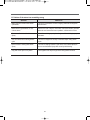
5. Problem: There Is Lint On My Clothes
Question
What to Do
• Is your lint filter full?
Please refer to the manual section on cleaning the lint filter, and
please confirm that the lint filter is clean. It is important that the lint
filter is clean before each new load of laundry.
• Did you properly sort your load of
laundry?
In order to reduce the amount of lint in a load of laundry, sort lint
producers (like a fuzzy white cotton towel) separately from clothes
that might catch lint (such as a pair of black linen pants).
• Do your clothes have excess static
electricity?
See comments below under. There Is Static In My Clothes After
Drying.
• Did you overload your dryer?
Divide your larger load into smaller loads.
• Did you place any paper, tissue, or other
similar material in the load?
Sometimes a person might forget to take a piece of paper or a tissue
out of a pocket, and this paper, tissue, or similar material can cause
excess lint in a load of laundry.
Confirm that the pockets of pants, shirts, and other articles of clothing
are empty before washing and drying.
6. Problem: There Is Static In My Clothes After Drying
Question
What to Do
• Did you use fabric softener?
Try using a fabric softener to reduce static electricity.
• Did you over dry the load of laundry?
Over-drying a load of laundry can cause a build up of static electricity.
Try using a fabric softener or adjust your settings and use a shorter
drying time.
• Are you drying synthetic, permanent
press and blends?
These materials can cause static to build up in a load of dried clothes.
Try using a fabric softener.
7. Problem: The Drying Time Is Not Consistent
Question
• Are you using consistent heat settings
and consistent load sizes?
What to Do
The drying time for a load will vary depending on the heat setting, the
type of heat used (electric, natural or LP gas), the size of the load, the
type of fabrics, the wetness of the clothes and the condition of the
exhaust ducts and lint filter.
8. Problem: Water Is Found Around The Cabinet Cover When Opening The Door.
Question
• Is water found around cabinet cover
when opening the door?
What to Do
This is normal because this is condensed moisture by drying.
36
9. Problem: It Takes Too Long For My Clothes To Dry
Question
• Did you properly sort your loads of
laundry?
What to Do
Separate heavy weight items from light weight items when creating
loads.
• Are you drying large loads of heavy
fabrics?
Heavy fabrics take longer to dry because they tend to retain more
moisture. To help reduce and maintain more consistent drying times
for large and heavy fabrics,separate these items into smaller loads of
a consistent size.
• Are the dryer controls properly set?
Use the appropriate control settings for the type of load you are drying.
• Is the lint filter clean before each new
load of laundry?
Please confirm that the lint filter is clean prior to each new load of
laundry.
• Are the exhaust ducts clear and properly
configured?
Confirm through review of the appropriate sections of this manual that
the exhaust venting ductwork is properly configured. Confirm that the
venting is free of obstructions. Confirm that the outside wall dampers
are moving freely, that the dampers are not pushed in, and that
nothing has been set against the dampers.
• Is the fuse blown, or is the circuit breaker
tripped?
Check your home’s or laundry room’s fuse box/circuit breaker box
and replace the fuse or reset the circuit breaker.
(IMPORTANT: electric dryers generally use two fuses or breakers.)
• Did you overload your dryer?
Divide your larger load into a number of smaller loads.
• Did you under load your dryer?
If you are only drying a handful of items, add a few extra pieces to
help ensure proper tumbling action.
10. Problem: My Clothes Are Wrinkled
Question
• Are you over drying your laundry?
What to Do
Over drying a load of laundry can lead to wrinkled clothes. Try a
shorter drying time, and remove items while they still retain a slight
amount of moisture.
• Are you removing your laundry from the
Remove your laundry from the dryer after the drying cycle ends and
dryer soon after the drying cycle is complete? either hang or fold the items.
11. Problem: My clothes are shrinking
Question
• Are you following the care instructions for
your garment?
What to Do
To avoid shrinkage, please carefully follow the care and use
instructions for your garment, because some fabrics will naturally
shrink when washed. Other fabrics can be washed but will shrink
when dried in a dryer.
37
12. Problem: If the steam has something wrong
Question
What to Do
• Water drips from nozzle when steam
cycle starts.
This is the condensation of water. Dripping water will be stopped in
the short time.
• Steam doesn’t generate but no error
code is shown
Check if the cord of dryer is connected. If the steam doesn’t generate
when the cord connection has no problem, call the service center.
• Garments still wrinkled after Steam
Spray
Check if the clothing quantity is so large and if the clothing is proper to
the steam.
• The drum does not turn during Steam
cycle
The drum is stopped for the stay of the water vapor during steam
cycle.
• Odors remain in clothing after Steam
Spray
The odor of clothing remains in spite of the use of Steam Spray be
sure to use the Steam Spray after normal cycled cleaning.
• Top plate of the dryer is very warm
The top plate of the dryer will get warm during steam functions.
38
DAEWOO DRYER LIMITED WARRANTY - USA
Your DAEWOO will be will repaired or replaced, at DAEWOO's option, if it proves to be defective in material or
workmanship under normal use, during the warranty period ("Warranty Period") set forth below, effective from the date
("Date of Purchase") of original consumer purchase of the product. This limited warranty is good only to the original
purchaser of the product and effective only when used in the United States, including Hawaii, and U.S. Territories.
WARRANTY PERIOD :
LABOR : ONE YEAR from the Date of Purchase.
PART : ONE YEAR from the Date of Purchase.
Replacement Units and Repair Parts may be new or factory remanufactured.
Replacement Units and Repair Parts are warrantyed for the remaining portion of the original unit's warranty period.
HOW SERVICE IS HANDLED :
IN-HOME Service: Please retain dealer's dated bill of sale or delivery ticket as evidence of the Date of Purchase for
proof of warranty, and submit a copy of the bill of sale to the service person at the time warranty service is provided.
Please call 1-877-393-7823(1-877-DWESVC3) and choose the appropriate option to locate your nearest
DAEWOO Autorized Service Center or visit website at : http://www.e-daewoo.com
THIS WARRANTY IS IN LIEU OF ANY OTHER WARRANTY, EXPRESS OR IMPLIED, INCLUDING WITHOUT
LIMITATION, ANY WARRANTY OF MERCHANTABILITY OR FITNESS FOR A PARRICULAR PURPOSE.
TO THE EXTENT ANY IMPLIED WARRANTY IS REQUIRED BY LAW, IT IS LIMITED IN DURATION TO THE
EXPRESS WARRANTY PERIOD ABOVE.
NEITHER THE MANUFACTURER NOR ITS U.S DISTRIBUTOR SHALL BE LIABLE FOR ANY INCIDENTAL
CONSEQUENTIAL, INDIRECT, SPECIAL, OR PUNITIVE DAMAGES OF ANY NATURE. INCLUDING WITHOUT
LIMITATION, LOST REVENUES OR PRO PROFITS, OR ANY OTHER DAMAGE WHETHER BASED IN
CONTRACT, TORT, OR OTHERWISE.
Some states do not allow the exclusion or limitation of incidental or consequential damages or limitations on how an
implied warranty lasts, so the above exclusion or limitation may not apply to you. This warranty gives you specific legal
rights and you may also have other rights that vary from state to state.
THIS LIMITED WARRANTY DOES NOT APPLY TO :
Service trips to your home to deliver, pick up, and/or install the product, instruct, or replace hose fuses or correct wiring,
or correction of unauthorized repairs.
Damages or operating problem that result from misuse, abuse, operation outside environmental specifications or
contrary to the requirements of precautions in the Operating Guide, accident, vermin, fire, flood, improper installation,
acts of God, unauthorized modification or alteration, incorrect electrical current or voltage, or commercial use, or use for
other than intended purpose.
The cost of repair or replacement under these excluded circumstances shall be borne by the consumer.
CUSTOMER INTERACTIVE CENTER NUMBER
To obtain Customer Assistance, Product Information, or Dealer or Authorized Service Center location:
Call 1-877-393-7823(1-877-DWESVC3) and select the appropriate option from the menu. Or visit our website :
http://www.e-daewoo.com
TO CONTACT DAEWOO ELECTRONICS BY MAIL:
DAEWOO Customer Service
300-3E State Hwy Rt 17 South
Lodi,NJ 07644
Version : 2008-06-13 Rev3
ABOUT THIS MANUAL
VISION CREATIVE, INC.
서울 종로구 통의동
6번지 이룸빌딩 4층
담
당
전은일 님
브 랜 드
DAEWOO
B. MODEL
DWR-WE5413WC/SC/RC
언
어
영어
DWR-WE6413WC/SC/RC
MODEL
미주향 DRYER MANUAL
일
1차
정
2차
3차
4차
제
판
인
한
쇄
MEMO 접수: (총39p)
11.09.16-표지 _ 신규 1p
연락처
VISION 담 당
방 문 수
TEL: 730-0660 FAX: 730-3788