1
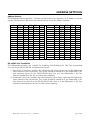
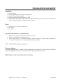
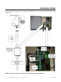
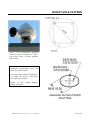
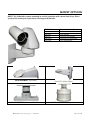
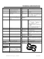
SIDEWINDER Series SW720 : 24VAC Installation Manual R1109 TABLE OF CONTENTS INFORMATION …………………………………………………………………………… Page 3 PRODUCT WARRANTY AND REPAIR …………………………………………………… Page 4 SAFEGUARDS AND TOOLS ……………………………………………………………… Page 6 INTRODUCTION ………………………………………………………………………… Page 7 INSTALLATION PLANNING ……………………………………………………………… Page 8 ADDRESS SETTINGS …………………………………………………………………… Page 9 INSTALLATION AND SETUP …………………………………………………………… Page 10 OVERVIEW ……………………………………………………………………………… Page 11 INTERFACE PANEL ……………………………………………………………………… Page 12 INTERFACE BOARD WIRING …………………………………………………………… Page 13 ADDRESS AND COMMUNICATION SETTINGS ………………………………………… Page 14 MOUNT HOLE PATTERN ………………………………………………………………… Page 15 MOUNT OPTIONS ……………………………………………………………………… Page 16 TECHNICAL SPECIFICATIONS ………………………………………………………… Page 17 ©WTI (Wireless Technology, Inc.) : Sidewinder Page 2 of 18 INFORMATION FCC NOTICE This device complies with Part 15 of the FCC Rules. Operation is subject to the following two conditions: 1.) This device may not cause harmful interference. 2.) This device must accept any interference that may be received, including interference that may cause undesired operation. READ THIS MANUAL Every effort has been made to insure that this WTI system is of the highest quality. This product has been carefully inspected to comply with rigid quality standards before shipment to you. In consideration of your investment and the desire to obtain full performance capability engineered into your new WTI product, we recommend that you read this manual before attempting to operate your system. FOR MORE ASSISTANCE OR MORE INFORMATION WTI (Wireless Technology, Inc.) 2064 Eastman Avenue, Suite 113 Ventura, CA 93003-7787 TOLL FREE. 866/gotowti (468-6984) TEL. 805/339-9696 FAX. 805/339-0932 EMAIL: [email protected] INTERNET: http://www.gotowti.com http://www.wirelesstech.com or The software / firmware furnished with the equipment is confidential to and is copyrighted by Wireless Technology, Inc. (WTI) It is not to be copied or disclosed in any manner without the consent of Wireless Technology, Inc. (WTI). The software/firmware is furnished to the purchaser under a license for use on a single system. Information furnished by Wireless Technology, Inc. (WTI) is believed to be accurate and reliable. However, no responsibility is assumed by Wireless Technology, Inc. (WTI) for its use or for any infringements of other rights of third parties, which may result from its use. No license is granted by implications or otherwise under any patent or patent rights of Wireless Technology, Inc. (WTI) ©2009 Wireless Technology, Inc. (WTI) All rights reserved. ©WTI (Wireless Technology, Inc.) : Sidewinder Page 3 of 18 PRODUCT WARRANTY AND REPAIR PRODUCT WARRANTY We appreciate your purchase of Wireless Technology, Inc. (WTI) security products. We take pride in the quality of our products and have manufactured each new WTI product to exacting quality standards. In normal use, it will provide you with years of satisfactory performance. However, should you experience difficulty; you are protected under the provisions of this warranty. WTI warrants to the original user a product that is free of defects in materials and workmanship in normal use. WTI warrants to the original user that WTI’s products will be free of defects in materials and workmanship in normal use for a period of 12 months from the date of sale. WTI’s obligation under this warranty shall be limited to the repair, including all necessary parts and the cost of labor connected therewith, or at our option, the replacement of any product that shows evidence of a manufacturing defect within the warranty period. This warranty is extended to all WTI products purchased and used within the United States of America and is valid only when service is rendered by the authorized WTI (Wireless Technology, Inc.) Warranty Station. This warranty shall not apply to appearance or accessory items including, but not limited to, knobs, connectors, cabinets and connecting cables. This warranty shall not, in addition, apply to repairs or replacements necessitated by any cause beyond the control of WTI including, but not limited to, acts of nature, improper installation, misuse, lack of proper maintenance, accident, voltage fluctuations, unauthorized repairs or modifications. This warranty becomes void in the event serial numbers are altered, defaced or removed, or an attempt is made to field service or alter performance of any WTI products. WTI reserves the right to make changes in design, or to make additions to, or improvements upon, products without incurring any obligation to install the same on products previously manufactured. The foregoing is in lieu of all other warranties expressed or implied and WTI neither assumes nor authorizes any person to assume for it any other obligation or liability in connection with the sale of our products. In no event shall WTI or its Authorized Dealers be liable for special or consequential damage arising from the use of this product, or any delay in the performance of this warranty due to causes beyond its control. ©WTI (Wireless Technology, Inc.) : Sidewinder Page 4 of 18 PRODUCT WARRANTY AND REPAIR REPAIR AUTHORIZATION Please contact Wireless Technology, Inc. (WTI), to obtain a repair authorization number (RA) and provide the following information: 1.) Product Model & Serial Numbers. 2.) Date of shipment, purchase order number, sales order number or WTI invoice number. 3.) Details of the defect or malfunction. If there is a dispute regarding the warranty or product, which does not fall under the warranty conditions stated within the description of the written warranty, please include a written explanation with the product when returned. SHIP FREIGHT PRE-PAID TO: WTI (Wireless Technology, Inc.) 2064 Eastman Avenue, Suite 113 Ventura, CA 93003-7787 TEL 805/339-9696 FAX 805/339-0932 RETURNS No unauthorized returns will be accepted. All returns must have an authorized (RA) number issued by the factory (CA number if returned for credit and RA number if returned for repair). Products returned for repair or credit will be rejected if no authorization number has been issued or freight has not been pre-paid. All merchandise returned for credit will be subject to a 20% restocking and refurbishing charge. ©WTI (Wireless Technology, Inc.) : Sidewinder Page 5 of 18 SAFEGUARDS AND TOOLS IMPORTANT SAFEGUARDS 1.) Read Instructions. It is important to read all safety and operating instructions before installing or using this equipment. 2.) Retain Instructions. Retain this manual and any supplements for future reference. 3.) Follow Instructions. Follow all instructions herein for use of this equipment. 4.) Heed all warnings. Adhere to all warnings on the equipment, and in this manual. 5.) To reduce the risk of electric shock or equipment damage, work on the unit only when the power is shut off and is unplugged from its power source to prevent accidental activation. Also take precautions to avoid contact between the equipment and other electrical wires or power sources that may be present at the installation site. RECOMMENDED TOOLS AND ACCESSORIES FOR PROPER INSTALLATION 1.) Tie-wraps to secure cable runs. 2.) #1 Phillips-head screwdriver is required to remove the access panel over the Dip Switches. 3.) A small slot (flat-head) screwdriver can be used to move the Dip Switches to the required positions for termination and address settings. 4.) Cordless power drill. 5.) Set of open end or SAE wrenches. 6.) Silicone caulking compound for antenna connector. 7.) Self-sealing connector tape - Used to weatherproof all outdoor cable connections. 8.) ¾” PVC flex conduit if boxes are mounted outdoors. 9.) Hand held radios. OTHER EQUIPMENT REQUIRED FOR SETUP 1.) A P/T/Z controller that supports Pelco D Code will be required to set the preset and tour features. WTI’s HHC-SW or DTC-720 controllers provide all of the necessary functions required to set all the preset and tour features of the Sidewinder camera. 2.) A video monitor will be required to view the video output of the Sidewinder to set the positions of the various Presets. WTI (Wireless Technology, Inc.) recommends the use of RG59/U such as Belden 8241 or equivalent 75Ω coaxial cable with 22-gauge solid copper center conductor and foam polyethylene dielectric. Either RG6/U or RG11/U would make an excellent substitute. Long coaxial cable runs cause signal degradation and/ or “SYNC” discrepancies. Limit RG59/U cable lengths to 800 feet. For coaxial runs from 800 feet to 1000 feet, use RG6/U or RG11/U. Do not use screw on type BNC connectors. They are not suited for reliable installations. NOTE: IT IS RECOMMENDED THAT YOU CONNECT YOUR SYSTEM TOGETHER AND VERIFY OPERATION BEFORE FIELD INSTALLATION. ©WTI (Wireless Technology, Inc.) : Sidewinder Page 6 of 18 INTRODUCTION The Sidewinder operates on 24VAC. Typical installations include an interface panel which contains all breakout points for wiring the Sidewinder umbilical cable as well as the field wiring for prime power (120VAC or 220VAC), data, and video. The Sidewinder utilizes Pelco-D protocol for PTZ control. Four conductors, full-duplex RS-485/RS422 connections are provided for advanced camera control functions, however, only two conductors are required for normal P/T/Z camera control features. Mounts Sidewinder must be mounted in an upright orientation. NOTE: Set camera address before mounting. The following mount options are available: 1.) Pedestal 10” or 24” (SWPM10 or SWPM24) 2.) Wall Mount (SWWM1) 3.) Pole Mount – add pole mount bracket (SWVPA) to the Wall mount. 4.) Horizontal Pole Mount (SWHPM1) 5.) Post Top Mount (SWPTM1) 6.) Custom mounts Interface Panel A. Surge Protection: The Interface Panel provides the following surge protection for equipment connected to the Sidewinder camera. a. 90V 10KA Gas Discharge Tube protection on 24VAC, video, TX data and RX data umbilical cable lines. b. 18V 40A 300W Bi-directional Transil surge arrestors on TX and RX data lines. c. 6V 2KW low capacitance transient voltage suppressor across video signal lines. B. Signal Connections: The following connection interfaces are provided with the Sidewinder Interface Panel. a. AC Mains power – Screw terminals are provided for AC Line, AC Neutral and AC Ground signals. b. Video Output – A Single BNC connector is provided for the Sidewinder camera video output signal. c. P/T/Z camera control – A removable Phoenix style 5 terminal plug with screw terminals is provided for connecting either a 4 conductor plus shield cable or a 2 conductor plus shield cable for P/T/Z control of the camera. C. Voltage Selection and Fusing a. The interface panel incorporates a switch for selecting between 110VAC and 220VAC operation. b. A 5x20mm fuse holder is provided to accept the 1A Slow Blow fuse. ©WTI (Wireless Technology, Inc.) : Sidewinder Page 7 of 18 INSTALLATION PLANNING Umbilical Cable Breakout The umbilical cable incorporates the following conductors for the various signals associated with the Sidewinder camera: 1.) Two white wires for one phase of the 24VAC power. 2.) Two black wires for the other phase of the 24VAC power. 3.) One coaxial cable for the video output signal. 4.) One white with orange stripe wire for TX+ data. 5.) One orange with white stripe wire for TX- data. 6.) One blue with white stripe wire for RX+ data. 7.) One white with blue stripe wire for RX- data. 8.) One green with yellow stripe connected to camera chassis ground. 9.) One Data Shield Drain wire connected to camera chassis. 10.) One Overall Shield Drain wire connected to camera chassis. Layout Planning 1.) When planning the installation, the limits of the various signal and power cables required should be kept in mind. 2.) Umbilical Cable – The maximum distance between the Sidewinder camera and the Sidewinder Interface Panel is 150 feet. If a longer distance is required, the AC power, video and control signals can be extended using separate cables after the Sidewinder Interface Panel. Keep in mind, though, that the surge protection for the signals is installed within the Sidewinder Interface Panel, and any cable extension will not be protected from surges at the Sidewinder Interface Panel. 3.) AC Power – The Sidewinder camera is designed to operate with 89VAC to 135VAC present at the AC power terminals of the Sidewinder Interface Panel with a maximum 150 foot umbilical cable. If the total cable run must be longer than 150 feet, the AC Power wiring should be extended on the 120VAC side of the Interface Panel. 4.) P/T/Z Data – The Sidewinder camera operates with Pelco D Code protocol, running at 2400 Baud. This allows very long PTZ data cables to be used. The optimum twisted pair or dual twisted pair cable impedance is 120 Ohms. Under normal circumstances the AC power wiring and video cable lengths will be the limiting factor in any installation. 5.) Video Signal – The maximum recommended length of the video cabling, including the umbilical cable and any other additional video cabling is 500 feet, to maintain optimum video quality. The Sidewinder Interface Panel provides only surge protection for the video signal. It does not provide any signal boost or equalization. ©WTI (Wireless Technology, Inc.) : Sidewinder Page 8 of 18 ADDRESS SETTINGS Address Settings The Sidewinder camera provides 5 switches on Dip Switch 1 for selecting 1 of 32 addresses for the camera. The following table shows the switch settings versus the address numbers. Address 1 2 3 4 5 6 7 8 9 10 11 12 13 14 15 16 SW5 OFF OFF OFF OFF OFF OFF OFF OFF OFF OFF OFF OFF OFF OFF OFF OFF SW4 OFF OFF OFF OFF OFF OFF OFF OFF ON ON ON ON ON ON ON ON SW3 OFF OFF OFF OFF ON ON ON ON OFF OFF OFF OFF ON ON ON ON SW2 OFF OFF ON ON OFF OFF ON ON OFF OFF ON ON OFF OFF ON ON SW1 OFF ON OFF ON OFF ON OFF ON OFF ON OFF ON OFF ON OFF ON Address 17 18 19 20 21 22 23 24 25 26 27 28 29 30 31 32 SW5 ON ON ON ON ON ON ON ON ON ON ON ON ON ON ON ON SW4 OFF OFF OFF OFF OFF OFF OFF OFF ON ON ON ON ON ON ON ON SW3 OFF OFF OFF OFF ON ON ON ON OFF OFF OFF OFF ON ON ON ON SW2 OFF OFF ON ON OFF OFF ON ON OFF OFF ON ON OFF OFF ON ON SW1 OFF ON OFF ON OFF ON OFF ON OFF ON OFF ON OFF ON OFF ON RS-485/RS-422 Termination The Sidewinder provides two switches for enabling and disabling the 120 Ohm termination resistors for the RS-485/RS-422 communication signals. 1.) Dip Switch 2 Position 8 enables the termination for signals being sent to the Sidewinder when turned to the ON position. This switch should be turned on if the Sidewinder is the only receiving device on the RS-485/RS-422 data line, or if the Sidewinder is the last receiver connected to the line in a daisy chain topology. 2.) Dip Switch 2 Position 7 enables the termination for signals being sent from the Sidewinder when turned to the ON position. This switch should be turned on if the Sidewinder is the only transmitting device on the RS-485/RS-422 data line, or if the Sidewinder is the first transmitter connected to the line in a daisy chain topology. ©WTI (Wireless Technology, Inc.) : Sidewinder Page 9 of 18 INSTALLATION AND SETUP Installation 1.) 2.) 3.) 4.) 5.) Install mount. Mount Sidewinder (see mount hole pattern). Install J-Box (Interface panel). Umbilical cable from Sidewinder to J-Box. Power cable, data cable, video cable from J-Box to power source, data feed, and video feed. (Refer to Interface panel and interface board pages). Setup 1.) Verify pan, tilt, and zoom operations. 2.) Set presets. 3.) Set tours. Operation / Maintenance / Troubleshooting • • • Speed – Pan and tilt speed reduces relative to zoom. Presets – avoid presets aiming into sun. Water spots on glass – should water spots become evident in video, simply squirt/douse the camera face plate with a squirt gun during day light hours. NOTE: HARD WATER will leave mineral deposits Firmware Updates The Sidewinder firmware is stored in field upgradeable Flash memory. Please consult the factory for detailed update instructions should a firmware upgrade become necessary. NOTE: Always set the camera address before mounting. ©WTI (Wireless Technology, Inc.) : Sidewinder Page 10 of 18 OVERVIEW ©WTI (Wireless Technology, Inc.) : Sidewinder Page 11 of 18 INTERFACE PANEL Specify 120 VAC or 220 VAC when ordering. Model SWIP1 series interconnect panels contain surge suppression. NOTE: The interface panel is required for all Sidewinder camera installations. ©WTI (Wireless Technology, Inc.) : Sidewinder Page 12 of 18 INTERFACE BOARD WIRING Wiring notes for installer supplied cables 1.) 120 VAC Wiring: Conductors and shielding per electrical code. Recommend SJ00W 18x3 carolprene. 2.) Video Out Wiring: RGU59 standard BNC. Recommend Belden 9259 75Ω video cable. 3.) P/T/Z Data Wiring: IMPORTANT – a 4-wire conductor is required for the P/T/Z data. This will be needed for future field software updates. Recommend Belden 3107A 2-pair shielded. ©WTI (Wireless Technology, Inc.) : Sidewinder Page 13 of 18 ADDRESS AND COMMUNICATION SETTINGS Set Camera address before mounting. ©WTI (Wireless Technology, Inc.) : Sidewinder Page 14 of 18 MOUNT HOLE PATTERN NOTE: The Sidewinder pictured above has been attached to a posttop mount and a custom parapet pole mount. Use 5/16-18 bolts allowing for ½” maximum penetration into the base. Use lock washers. Post top mount (shown in photo) is a ¼ plate and used ½” long bolts with split-ring washers. Always set the camera address before mounting. ©WTI (Wireless Technology, Inc.) : Sidewinder Page 15 of 18 MOUNT OPTIONS NOTE: The Sidewinder requires mounting in vertical orientation with camera head at top. Please specify which mount you require when ordering your Sidewinder. SWPM10 SWPM24 SWWM1 SWVPA SWHPM1 SWPTM1 Pedestal – 10” tall Pedestal – 24” tall Wall Mount Vertical Pole Mount Horizontal Pole Mount Post Top Mount Model #SWWM1: Wall Mount Model #SWWM1 and #SWVPA: Wall Mount with Vertical Pole Mount Adapter Model #SWHPM1: Horizontal Pole Mount Model #SWPTM1: Post Top Mount ©WTI (Wireless Technology, Inc.) : Sidewinder Page 16 of 18 TECHNICAL SPECIFICATIONS Camera Imager Resolution Effective Pixels Lens ¼” color progressive scan, interline transfer CCD NTSC or PAL, 520 horizontal TV lines NTSC @ 768 x 494, PAL @ 768 x 582 Focal Length High durability 35X optical zoom, F1.4 with 10X digital zoom 3.4mm ~ 120mm S/N Ratio Iris >52 dB Auto or manual override Shutter Auto or manual override Focus Auto or manual override Sync IR Cut Filter Internal or external Auto or manual (on/off) Sensitivity 0.5 Lux typical down to 0.01 Lux in IR mode Electrical Power Output Power Consumption (with heater on) Environmental Ambient Temperature Limit Humidity Mechanical Weight Vibration (less lens) Air Contaminants 14.5 lbs. (6.5 kgs.) 3g (rms) random, 5 to 1000 Hz, any axis Withstands exposure to sand, dust, fungus, salt atmosphere, per MIL-E-5400T, paragraph 3.2.24.7, 3.2.24.8 and 3.2.24.9 Positioner Pan / Tilt Drive Preset Title Generation Tours Pan Angle Range: Continuous 360° Tilt Angle Range: Continuous 360° Pan Speed: 100°/sec – proportional to zoom Tilt Speed: 50°/sec – proportional to zoom Pan/Tilt Encoder Resolution: 0.05° Pan/Tilt Repeatability: 0.05° 64 preset positions 1 line of 24 characters for camera ID and preset ID 8 tours of 32 presets with individual dwell settings per preset Automatic camera image inversion Inverted Operation Communications Communication RS-422 or RS-485 standard, RS/ Physical Layer 232 for RackVision™ (specify on order) Protocol WTI proprietary industry standard or optional NTCIP Firmware Field upgradable flash memory 24 VAC ± 6 VAC 50W -29° F to +165° F (-34° C to +74° C); Conforms to NEMA 2.1.5.1 standard TS2 for traffic control systems 100% relative humidity ©WTI (Wireless Technology, Inc.) : Sidewinder Page 17 of 18 Wireless Technology, Inc. (WTI) 2064 Eastman Avenue, Suite 113 Ventura, CA 93003-7787 USA tel 805/339-9696 fax 805/339-0932 email: [email protected] www.gotowti.com www.wirelesstech.com Due to Wireless Technology, Inc. (WTI) continuing efforts to engineer the best product that is most responsive to our customer’s needs, the above specifications are subject to change without notice. ©WTI (Wireless Technology, Inc.) : Sidewinder Page 18 of 18