1
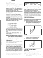
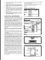
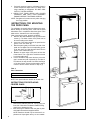
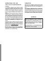
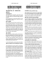
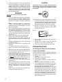
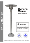
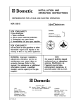
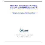
Silhouette
by Dometic
INSTALLATION AND
OPERATING INSTRUCTIONS
REFRIGERATOR FOR LP-GAS AND ELECTRIC OPERATION.
S1521 S1531
Automatic-Manual Energy Selector
FOR YOUR SAFETY
If you smell gas:
1. Open windows.
2. Don’t touch electrical switches.
3. Extinguish any open flame.
4. Immediately call your gas supplier.
Contents:
Installation
Instructions for use
Gas equipment
Electric equipment
Maintenance
Fault tracing
FOR YOUR SAFETY
Do not store or use gasoline or other
flammable vapors and liquids in the
vicinity of this or any other appliance.
WARNING: Improper installation,
adjustment, alteration,service or
maintenance can cause injury or
property damage. Refer to this
manual. For assistance or additional
information consult a qualified
installer, service agency or the gas
supplier.
Dometic
Our goal.. . your satisfaction.
Corporate Office
2320 Industrial Parkway Elkhart, IN 46515
USA
Service Office
The Dometic Corporation
509 South Poplar Street
LaGrange, IN 46761
822 60 45-00
CANADA
Dometic Distribution Inc.
866 Langs Drive
Cambridge,Ontario
N3H 2N7 Canada
Phone: 519-653-4390
Page
3-8
9-12
13
13
13-14
14-15
PROTECTION PLATE
FIG. 1
D
2 - WAY display panel.
b
1[FF
=p AC
I
B
f
3 - WAY display panel.
w
$F
I
c
I
E
F
FIG. 2
?
j$@%$
/
7,
I
F
I
I
F
LEGEND 2-WAY AMES Model
LEGEND 3-WAY AMES Model
1. Main Power Button ON/OFF
2. AUTO/GAS Mode Selector Button
3. Temperature Selector Button
1. Main Power Button ON/OFF
2. DC Mode Selector Button
3. AUTO/GAS Mode Selector Button
4. Temperature Selector Button
B.
C.
D.
E.
AC Mode Indicator Lamp
GAS Mode Indicator Lamp
AUTO Mode Indicator Lamp
CHECK Indicator Lamp
(GAS Mode Only)
F. Temperature indicator Lamps
A.
B.
C.
D.
E.
DC Mode Indicator Lamp
AC Mode Indicator Lamp
GAS Mode Indicator Lamp
AUTO Mode Indicator Lamp
CHECK Indicator Lamp
(GAS Mode Only)
F. Temperature Indicator Lamps
INSTALLATION
GENERAL INSTRUCTION
This appliance is designed for storage of foods and
storage of frozen foods and making ice.
The refrigerators outlined herein have been design certified by A.G.A. under the ANSI 221.19 Refrigerator Standard for installation in a mobil home or recreational
vehicle and areapproved by the Canadian Gas Association.
The certifications are, however contingent on the installation being made in accordance with the following instructions as applicable.
In the U.S.A., the installation must conform with:
1. National Fuel Gas Code ANSI Z223.1 -(latest edition)
2. Manufactured Home Construction and Safety Standard, Tile 24 CFR, Part 3280.
3. Recreational Vehicles ANSI Al 19.2-(latest edition).
The unit must be electrically grounded in accordance
with the National Electric Code ANSI/NFPA 70-(latest
edition) when installed, if an external alternating current
electrical source is utilized.
4. Any applicable local code.
In CANADA, the installation must conform with:
1. Current CGA B 149 Gas Installation Codes
2. Current CSA Standard Z 248.4 GAS-EQUIPPED
RECREATIONAL VEHICLES AND MOBIL HOUSING.
3. Any applicable local code
The unit must be electrically grounded in accordance
with the current CANADIAN ELECTRICAL CODE C 22
Parts 1 and 2.
VENTILATION
GAS CONNECTION
Hook-up to the gas supply line is accomplished at the
manual gas valve, which is furnished with a 3/8” SAE
(UNF 5/8” -18) male flare connection. All completed connections should be checked for leaks with soapy water.
WARNING
DO NOT use a flame to check for gas leaks.
The gas supply system must incorporate a pressure
regulator to maintain a supply pressure of not more than
11 inches water column.
When testing the gas supply system at test pressures in
excess of 1/2 psig, the refrigerator and its individual
shutoff valve must be disconnected from the gas supply piping system.
When testing the gas supply system at pressures less
than or equal to 1/2 psig, the appliance must be isolated
from the gas supply piping system by closing its inividual
manual shutoff valve.
In case detailed instructions on the installation and connection to the gas supply are required, contact your
dealer or distributor.
ELECTRICAL CONNECTION
120 Volts AC Connection
The refrigerator is equipped with a three prong
(grounded) plug for protection against shock hazards,
and should be plugged directly into a properly grounded
three prong receptacle. DO NOT cut or remove the
grounding prong from this plug. The free length of the
cord is 2 feet and therefore recommended that the receptacle be located to the left side of the refrigerator (viewed
from the rear) and approximately 6 inches from the floor
(see FIG. 3). This allows easy access through the vent
door. The cord should be routed to avoid contacting the
burner cover, flue cover or any other components that
could damage the cord insulation.
The installation shall be made in such a manner as to
separate the combustion system from the living space
of the mobii home or recreational vehicle. Openings for
air supply or for venting of combustion products shall
have a minimum dimension of not less than 1/4 inch.
Proper installation requires one lower fresh air intake and
one upper exhaust vent. The ventilation kiis shown in this
instruction manual have been certified for use with the
refrigerator models listed in the Table 2, “Certified Vent
System Kits” . The ventilation kits must be installed and
used without modification. An opening toward the outside at floor level in the refrigerator compartment must
be provided for ventilation of heavier-than-air fuel gases.
The lower vent of the recommended kiis is provided with
proper size openings. The flow of combustion and ventilating air must not be obstructed.
The lower side vent is fitted with a panel which provides
an adequate access opening for ready service ability of
the burner and control manifold of the refrigerator.
4
IG. 3
Table 1
Refrigerator Cut-Out Openings (inches)
Height
Width
Depth
Model
23.5
24.0
S 1521,S1531 43 1/4
12 Volts DC Connection
All refrigerator models require a 12 volt DC supply (even
though 2-way models are designed to operate on 120
volts AC and gas, a 12 volt DC control is required to maintain the automatic energy system). The DC lead connections are at terminals located at the rear of the
refrigerator. (see FIG. 1). One lead is marked positive (+)
and the other negative (-). Correct polarity must be observed when connecting to the DC supply.
Do not use the chassis or vehicle frame as one of the
conductors. Connect two wires at the refrigerator and
route to the DC supply.
12 Volts DC Connection 3-way models
The distance the current must travel from the battery to
the refrigerator dictates the AWG wire size to be used.
Should the wire be too small for the distance, a voltage
drop will result.
The voltage drop affects the wattage output of the 12 volt
cartridge heater and resultant refrigerator performance.
Recommended wire sizes are shown below.
Maximum total conductor wire length in feet and meters.
After refrigerator is mounted in place (insuring a combustion seal at the front mounting flange), the unit can
be secured by screws through the mounting flange and
hole(s) provided at floor level in the rear. Caps are
provided to cover the mounting flange screws.
Seal strips, provided with the refrigerator, must be in
position behind the mounting flange after the refrigerator
is installed in the wall enclosure. The seal must be continuos between the flange and the wall to assure combustion seal. Care should be taken when installing or
removing the refrigeratorthat the strips are not disturbed
or damaged.(See FIG. 8).
Lower Flange Installation
The lower flange is shipped as a loose part to prevent
damageduring shipment. The part is to be attached after
the refrigerator is set into the cut-out opening.
1. Install the lower flange by maneuvering it under and
behind the bottom hinge plate, as shown in FIG. 4
(the hinge will be located on either the right or left
side, depending on door swing preference).
The wires from the battery to the refrigerator must be of
large enough size to handle the load. The connections
must be clean, tight and free from corrosion. If not, a
resulting voltage drop will cause a decreased cooling
capacity.
INSTALLING REFRIGERATOR IN
ENCLOSURE
NOTE: DO NOT install the appliance directly on carpeting. Carpeting must be removed or
protected by a metal or wood panel beneath
the appliance which extends at least full
width and depth of the appliance.
2.
3.
Once the lower flange is slipped around the hinge,
the part will swing into place as shown in FIG. 5.
Secure the flange with screws provided.
CLEARANCES
Minimum clearances in inches to combustible materials
are: Top 0; Side 0; Bottom 0; Rear 0.
The refrigerator must be installed in a substantial
enclosure and must be level. When installing the
refrigerator in the endosure, all areas within the recess
in which the refrigerator is installed must be sealed.
Make sure that there is a complete seal between the front
frame of the refrigerator and the top, sides and bottom
of the enclosure. A length of sealing strip is applied to
the rear surface of the front frame for this purpose. The
sealing should provide a complete isolation of the
appliance’s combustion system from thevehicle interior.
The refrigerator, designed for built-in installation, requires opening dimensions as specified in Tablel.
FIG_ 5
TESTING LP GAS SAFETY
SHUTOFF
The gas safety shutoff must be tested after the
refrigerator is connected to LP gas supply.
To test the gas safety shutoff, proceed as follows:
1. Start the refrigerator and switch to gas mode. (see
start up instructions).
5
2.
3.
4.
5.
6.
Check that the gas flame is lit and the gas mode indicator lamp (C) is on.
Close the gas valve at the back of the refrigerator.
Wait for one minute. The check indicator lamp (E)
should now be lit and the gas mode indicator lamp
should be off.
Remove protection cover (see FIG. 1) and open the
gas valve. Test that no gas comes through the
burner jet. Use soupy water, rinse afterwords with
fresh water. Be careful not to damage the burner jet,
replace cover.
Make an ON-OFF operation with the main switch.
Normal gas operation should now return, operate
for at least five minutes.
Lower vent and roof jack must be A.G.A./CGA certified
for use with the refrigerator.
Roof jack opening must be centered directly above the
flue and condenser. (See FIG. 6 and 7.)
Table 2
Certified Vent System Kits
VENTILATION REQUIREMENTS
When installing the refrigerator in the enclosure, all areas
at the front (sides, bottom and top) and within the recess
in which the refrigerator is installed must be sealed so
the resultant installation will isolate the appliance combustion system from the vehicle interior.
Certified installation requires that one lower combustion
air intake and one upper exhaust vent be used. The
specified vent kit for this refrigerator must be installed as
directed by this manual without modification. Any deviation or substitution other than the specified vent kit will
void this certification and the factory warranty of the
refrigerator.
Venting must be in accordance with dimensions as
shown in FIG. 6. Any deviation will result in non-certification.
Lower vent is to be utilized as a service entrance door.
Opening of lower vent must be flushed or below bottom
of refrigerator.
The condenser and absorber tubes (see FIG. 6) must
receive a continual supply of cooler air in order to maintain proper refrigerator cooling. A recommended 0”
clearance between the back of the refrigerator and the
coach wall helps the ventilation efficiency. The air passage (ventilation zone) from the lower vent door to the
refrigerator coils and from the coils up through the roof
vent must be unobstructed. If the air becomes trapped
by obstructions, the refrigerator will start to lose its ability
to cool. The proper ventilation zone, as shown in FIG. 8,
will create a chimney effect to incure adequate circulation. It is important to block off the area above the
refrigerator cabinet from this ventilation zone (see FIG.
8). Also, air space at the sides of the refrigerator should
be minimized to prevent pockets of hot air from forming.
without adequate ventilation and/or with partial blockage of flue exhaust, incomplete combustion (on GAS
operation) can cause carbon monoxide to form. Not only
does the refrigerator lose efficiency, but a poisonous gas
can result.
In the event of a prdpane leak, the properly installed
lower vent door will allow the propane to " Weep " to the
outside of the floor level, preventing large pockets of gas
from collecting.
6
I
VENTILATION ZONE
VENTILATION ZONE
TOP VIEW
(LOOKING DOWN THROUGH OPENING)
FIG. 7
CUTOUT FOR ROOF JACK
F LUE
POCKETS SHOULD BE BAFFLED FOR PERFORMANCE
EFFICIENCY ALTHOUGH NOT REQUIRED FOR CERTIFICATION.
SEALED
SEAL STRIPS
SEAL STRIPS
Re-install mounting screws to refrigerator frame in
reverse sequence of steps B and C to attach doorhinge assembly to refrigerator. DO NOT COMPLETELY TIGHTEN SCREWS.
h. CHECK THAT DOOR OPENS AND CLOSES
PROPERLY AND THAT LATCH ASSEMBLY
ENGAGES BEFORE TIGHTENING SCREWS.
NOTE: Re-tighten all screws securely after changing
the hinge position.
9.
INSTRUCTIONS FOR MOUNTING
THE DOOR PANEL
The refrigerator is normally delivered without door panel.
Before starting the mounting work, check that the panel
dimensions are in compliance with those given in the
table and the instructions are read thoroughly.
When mounting the panel, proceed as follows):
A. Remove the door de&ration strip (2) with its two
screws (1). The lower comers of the panel have to
be cut according to the sketch.
B. Insert one of the vertical edges of the panel into the
groove of the door frame (3).
C. Bend the panel gently so that the free side of the
panel can be slipped into the corresponding groove
of the door frame (4). Slide the panel down into the
groove of the bottom frame (5).
D. Between the upper edge of the panel and the door
frame there is now a gap which should be covered
by the decoration strip.
E. Put the decoration strip across the door so that the
gap is covered and push it upwards (6). The tabs on
the inside of the strip should fii in behind the flange
of the door frame. Secure the decoration strip by
means of the two screws removed in Step A (1).
Table 3
Panel Dimensions
Models
S 1521, S 1531
21-19/32”x 36-1/16"
NOTE: Door panel thickness should not exceed 5/32”.
INSTRUCTIONS FOR REPLACING
CRISPER GLASS
FIG. 15
1.
2.
8
Remove the retainers (see FIG. 15) by prying out
from side of liner with a flat blade screwdriver being
careful not to damage the liner.
After removing the retainers slide new glass in place
and install new retainers supplied with kit.
NOTE: Retainers should only be removed for replacement of crisper glass as they are not reusable.
INSTRUCTIONS FOR USE
OPERATION
HOW TO START THE REFRIGERATOR
Before starting the refrigerator, check that all the manual
gas valves are in the ON position. DO NOT forget the
manual shutoff valve on the rear of the refrigerator, see
FIG. 1.
This refrigerator is equipped whith a semi Automatic
Energy Selector (AMES) control system, which can be
set to automatically select either 120 volt AC or LP gas
operation, or if desired Lp gas only. On 3-way models
the control system can manually be set to DC operation.
The refrigerator controls will work down to 9.6 volt DC.
Leveling
In an absorption refrigerator system, ammonia is liquified
in the finned condenser coil at the top rear of the
refrigerator. The liquid ammonia then flows into the
evaporator (inside the freezer section) and is exposed to
a circulating flow of hydrogen gas, which causes the ammonia to evaporate, creating a cold condition in the
freezer.
The tubing in the evaporator section is specifically
sloped to provide a continuous movement of liquid ammonia, flowing downward by gravity through this section. If the refrigerator is operated when it is not level and
the vehicle is not moving, liquid ammonia will accumulate in sections of the evaporator tubing. This will slow
the circulation of hydrogen and ammonia gas, or in
severe cases, completely block it, resulting in a loss of
cooling.
Any time the vehicle is parked for several hours with the
refrigerator operating, the vehicle should be leveled to
prevent this loss of cooling. The vehicle needs to be
leveled only so it is comfortable to live in (no noticeable
sloping of floor or walls).
When the vehicle is moving, the leveling is not critical as
the rolling and pitching movment of the vehicle will pass
to either side of level - keeping the liquid ammonia from
accumulating in the evaporator tubing.
WARNING
Most LP gas appliances used in recreational
vehicles are vented to the outside of the vehicle.
When parked close to a gasoline pump, it is possible that gasoline fumes could enter this type of
appliance and ignite the burner flame, CAUSING
A FlRE OR AN EXPLOSION.
FOR YOUR SAFETY, it is recommended that all LP
gas appliances which are vented to the outside
should be shut off when refueling.
3 - WAY display panel.
2 - WAY display panel.
START UP INSTRUCTIONS
A. A 12 volt DC supply must be available for the
electronic control to function.
B. Press the main power ON/OFF button (1) to the
DOWN position.
C. Press the TEMPERATURE SELECTOR BUTTON (3)
P-WAY Model or (4) 3-WAY Model until the lamp at
the desired setting is illuminated.
3-WAY MODEL
AUTO MODE
1.
2.
2-WAY MODEL
AUTO MODE
1.
2.
3.
Move the AUTO/GAS mode selector button (2) to
the DOWN position. (If 120 volts AC is available, the
AC mode indicator lamp (B) will illuminate indicating AC operation. If 120 volts AC is not available, the
GAS mode indicator lamp (C) will illuminate and the
control system will automatic switch to GAS operation.
If the CHECK indicator lamp (E) illuminates and the
GAS mode indicator lamp (C) is off, the controls
have failed to ignite the burner in the GAS mode.
GAS operation may be reset by pressing the main
power ON/OFF button (1) to the OFF than ON position. (see step 2 under GAS MODE)
Press the TEMPERATURE SELECTOR button (3)
until the lamp at the desired position is illuminated.
GAS MODE
1.
Move the AUTO/GAS mode selector button (2) to
the UP position_ The GAS mode indicator lamp (C)
will illuminate. After 45 seconds the burner should
be ignited and operating normally.
2. On the initial refrigerator start-up, it may take longer
than 45 seconds to allow air to be purged from the
gas line. If the gas does not ignite within 45 seconds
the CHECK indicator lamp (E) will illuminate and the
GAS mode indicator lamp (C) will go off. To reset
when the CHECK indicator lamp (E) is illuminated,
press the main power ON/OFF button (1) to the OFF
and then ON position.
NOTE: Do not continue to reset GAS operation if the
CHECK indicator lamp continues to be illuminated after
several tries.
3. Press the TEMPERATURE SELECTOR button (3)
until the lamp at the desired position is illuminated.
TO SHUT OFF THE REFRIGERATOR
The refrigerator may be shut off while in any mode of
operation by pressing the main power ON/OFF button
to the UP (OFF) position. This shuts off all DC power to
the refrigerator.
10
3.
4.
Press the DC mode selector button (2) to the UP
(OFF) position.
Move the AUTO/GAS mode selector button (3) to
the DOWN position. (If 120 volts AC is available, the
AC mode indicator lamp (B) will illuminate indicating AC operation. If 120 volts AC is not available, the
GAS mode indicator lamp (C) will illuminate and the
control system will automatic switch to GAS operation.
If the CHECK indicator lamp (E) illuminates and the
GAS mode indicator lamp (C) is off, the controls
have failed to ignite the burner in the GAS mode.
GAS operation may be reset by pressing the main
power ON/OFF button (1) to the OFF than ON position. (see step 2 under GAS MODE)
Press the TEMPERATURE SELECTOR button (4)
until the lamp at the desired position is illuminated.
GAS MODE
1.
Press the DC mode button (2) to the UP (OFF) position.
2. Move the AUTO/GAS mode selector button (3) to
the UP position. The GAS mode indicator lamp (C)
will iliimunate. After 45 seconds the burner should
be ignited and operating normally.
3. On the initial refrigerator start-up, it may take longer
than 45 seconds to allow air to be purged from the
gas line. If the gas does not ignite within 45 seconds
the CHECK indicator lamp (E) will illuminate and the
GAS mode indicator lamp (C) will go off. To reset
when the CHECK indicator lamp (E) is illuminated,
press the main power ON/OFF button (1) to the OFF
and then ON position.
NOTE: Do not continue to reset GAS operation if the
CHECK indicator lamp continues to be illuminated after
several tries.
4. Press the TEMPERATURE SELECTOR button (4)
until the lamp at the desired position is illuminated.
DC MODE
1.
2.
Press the DC mode indicator button (2) to the down
position.
Press the TEMPERATURE SELECTOR button (4)
until the lamp at the desired position is illuminated.
3 - WAY display panel.
2 - WAY display panel.
A
DESCRIPTION OF OPERATING
MODES
THERMOSTAT
The thermostat on the refrigerator controls both the gas
and electric operation, thereby eliminating the necessity
of resetting each time a different energy source is
employed.
After the initial start-up, the thermostat should be moved
from “COLDEST’ to the desired temperature setting,
usually about mid setting.
AUTO MODE
When operating in the AUTO mode, the AUTO mods indicator lamp (D) will illuminate. The control system will
automatically select between AC and GAS operation
with AC having priority over GAS. Either the AC indicator
lamp (B) or the G AS indicator lamp (C) will illuminate
depending on the energy source selected by the control
system. If the control system is operating with AC energy and it then becomes unavailable , the system will
automatically switch to GAS. As soon as AC becomes
available again the control will switch back to AC regardless of the status of GAS operation.
GAS MODE
When operating in the GAS mode the AUTO mode indicator lamp (D) will be off and the GAS mode indicator
lamp (C) will be illuminated. This mode provides LP gas
operation only. The control system will activate the ignition system and will attempt to light the burner for a
period of approximately45 seconds. If unsuccessful, the
CHECK indicator lamp (E) will illuminate and the GAS
mode indicator lamp (C) will turn off.
To restart GAS operation, press the main power ON/OFF
button (1) to the-OFF and then ON position. The control
system will attempt a new 45 second ignition sequence.
If the refrigerator has not been used for a long time or
the LP tanks have just been refilled, air may be trapped
in the supply lines. To purge the air from the lines may
require resetting the main power ON/OFF button (1)
three or four times. If repeated attempts fail to start the
LP gas operation, check to make sure that the LP gas
supply tanks are not empty and all manual shutoff valves in the lines are open. If the problem is still not corrected, contact a service center for assistance.
If the control is switched to AC or DC operation while the
CHECK indicator lamp is on, it will function properly, but
the CHECK indicator lamp will not go off until the main
power ON/OFF button is pressed to the OFF then ON
position.
D
DC.MODE (3-way models only)
When operating in the DC mode the DC mode indicator
lamp (A) will be illuminated. All other mode lamps will be
off. The DC mode overrides all other operating modes.
If one of the other operating modes is desired, the DC
selector button (2) must be in the UP (OFF) position.
BATTERY PROTECTION SYSTEM
The control system is equipped with a battery protection
system. A steady illuminated DC mode lamp (A) indicates that sufficient voltage is present at the terminal
block connections to operate the refrigerator normally.
If the input voltage is below approximately 12.8 volts DC
or should it drop below 12.8 volts DC during operation,
the DC mode lamp (A) will flash ON and OFF to signal a
low battery condition. In this condition the control will
continue to operate in DC mode for a maximum 10
minutes.
If the input voltage has not returned above 12.8 volts DC
within this time, the control will terminate DC operation.
A second battery protection system will terminate DC
operation immediately if the input voltage drops below
10.6 volts.
The DC mode lamp will continue to flash as long as the
input voltage remains below 12.8 volts. The input battery
voltage must rise above 12.8 volts for 25 minutes before
DC operation can resume.
As soon as the input voltage rises above the required
12.8 volts, the DC mode indicator lamp will stop flashing,
however, the control system will remain in the 25 minute
delay mode. This delay is to allow sufficient time for the
vehicle charging system to recharge the battery.
LIMP MODE OF OPERATION
This control system contains a feature where it will continue to operate the cooling system in the event of a
failure of a major operating component. Two different
modes of operation can occour in this category.
If for some reason the display module becomes non
functional, the control system will revert to full automatic
operation selecting the best energy source available with
AC,DC (3-way only) and GAS priority. The temperature
of the refrigerator will be maintained at the MID position
within normal temperature tolerances. The power
module will continually attempt to re-establish operation
of the display module.
The second limp mode of operation will execute when a
failure of the temperature sensing device or associated
electronic circuitry occurs. If this should occour, the control system will operate on the energy source selected
via the control panel. The cooling unit will run continuously on the selected energy source. The refrigerator
will continue to operate in this mode indefinitely or until
a new sensor is installed and the system is reset.
HOW TO USE THE REFRIGERATOR
FOOD STORAGE COMPARTMENT
The food storage compartment is completely closed and
unventilated, which is necessary to maintain the required
low temperature for food storage. Consequently, foods
having a strong odor or those that absorb odors easily
should be covered. Vegetables, salads etc. should be
covered to retain their crispness. The coldest positions
in the refrigerator are under the cooling fins and at the
bottom of the refrigerator. The warmer areas are on the
upper door shelves. This should be considered when
placing different types of food in the refrigerator.
FROZEN FOOD STORAGE
COMPARTMENT
Quick frozen soft fruits and ice cream should be placed
in the coldest part of the compartment which is at the
bottom of the aluminum liner. Frozen vegetables, may
be stored in any part of the compartment.
This compartment is not designed for deep or quick
freezing of food. Meat or fish, whether raw or prepared,
can be stored in the frozen food storage compartment
provided they are pre-cooled first in the refrigerator.
They can be stored about three times longer in the frozen
food compartment as compared to the fresh food compartment. To prevent food from drying out, keep it in
covered dishes, containers, plastic bags or wrapped in
aluminium foil.
ICE MAKING
CLEANING
Cleaning the refrigerator is usually done after it is
defrosted or put into storage. To clean the interior liner
of the refrigeratoruse lukewarm weak soda solution. Use
only warm water to clean the finned evaporator, ice trays
and shelves. NEVER use strong chemicals or abrasives
to clean these parts as the protective surfaces will be
damaged. It is important to always keep the refrigerator
clean.
SHUT OFF - STORAGE PROCEDURE
Shut off the refrigerator by pressing the main power
ON/OFF button to the UP (OFF) position.
If the refrigerator will not be in operation for a period of
weeks, it should be emptied, defrosted, cleaned and the
doors left ajar. The ice tray should also be dried and kept
outside the cabinet
CAUTION
DO NOT store explosive substances in the
refrigerator, such as cigarette lighter gas, petrol,
ether or the like.
Table 4
Ice cubes can be made in the ice tray placed in the
freezer compartment. The tray should be filled with water
to within 1/4" (5mm) from the top. For faster ice making,
the tray should be placed in direct contact with the
freezer bottom.
To release the ice cubes, seize the tray with both hands
and twist the tray. Cubes not required should be
replaced in the tray. Refill the tray with water and replace
the tray on the freezer shelf.
Ice will be made more rapidly if the thermostat is set at
its highest position.
It is a good idea to do this a few hours before the anticipated need for ice, but be sure to move back to normal setting, usually about mid setting when the ice is
formed. Food in the lower compartment may be frozen
if the setting is left on “COLDEST’ position.
DEFROSTlNG
Shut off the refrigerator by pressing the main power
ON/OFF button to the UP (OFF) position. Empty the
refrigerator, leaving the drip tray under the finned
evaporator, and the cabinet and freezer doors open.
Defrosting time can be reduced by filling the ice tray with
hot water and placing it on the freezer bottom.
CAUTION
DO NOT use a hot air blower. Permanent damage
could result from warping the metal or plastic parts.
DO NOT use a knife or an ice pick, or other sharp
tools to remove frost from the freezer shelf. They can
create a leak in the ammonia system.
12
When all frost is melted, dry the interior of the refrigerator
with a clean cloth. Replace all food and set thermostat
to the COLDEST temperature setting for a few hours.
Then reset the thermostat to the’desired setting, usually
at mid setting.
GAS EQUIPMENT ASSEMBLY
P R E S S U R E TEST PORT
FIG. 16
MAINTENANCE & SERVICE
ELECTRlC EQUIPMENT
CARTRIDGE HEATER
The heat necessary for the operation of an absorption
cooling unit is supplied by an electric heater mounted in
a pocket of the boiler system.
The 3-WAY Model is equipped with two electrical
heaters, one for 120 volt AC and one for 12 volt DC.
The 2-WAY Model is equipped with one electric heater
120 volt AC.
To replace the heater proceed as follows:
1. Disconnect the wall plug, and the 12 volt wires.
2. Remove the protection cover see FIG. 1
3. Remove the pover module cover see FIG. 1
4. Disconnect the heater leads.
5. With a pair of pliers unfold the lug holding the lid of
the boiler casing and open the lid.
6. Remove some insulation wool so that the heater is
accessible.
7. Turn and lift the heater out of its pocket.
8. Fit the new heater into the pocket.
9. Connect the leads and put on the power module
cover.
10. Reset the insulation and close the lid of the boiler.
11. Replace the protection cover.
FUSES
The 2-way AMES models are equipped with 2 fuses, one
for the refrigerator control system and one for the AC
cartridge heater.
The 3-way AMES models are equipped with a third fuse
for the DC cartridge heater. (see table below)
To replace fuse(s) proceed as follows.
1. Disconnect the wall plug, and the 12 volt wires.
2. Remove the power module cover. See FIG. 1.
3. Snap the fuse out of the fuse holder.
4. Fit a new fuse in to the fuse holder.
5. Replace the power module cover.
1.
REFRIGERATOR REMOVAL
Before working on the refrigerator make sure that
120 volt AC and 12 volt DC leads are disconnected.
Close the shutoff valve on the gas supply piping system. Disconnect the outgoing gas line from the gas
valve at the rear of the refrigerator. (see FIG. 1.)
Loosen the screws anchoring the refrigerator to the
enclosure and slide the refrigerator forward out of
the compartment.
When replacing the refrigerator make sure that the
sealing strips are properly positioned.
After ressemble the gas connection should be
checked for leaks.
2.
A.
PERIODIC MAINTENANCE
To keep your Silhouette refrigerator operating efficiently and safely, periodic inspection and cleaning
of several components once or twice a year is
recommended.
It is important to keep the area at the back of the
refrigerator clean. Check the lower vent, upper vent
and area between these openings for any obstructions such as bird/insect nests, spider webs, etc.
Clean the coils on the back of the refrigerator. Use
a soft bristled brush to dust off the coils.
It is important to keep the refrigerator area free from
combustible material, gasoline and other flammable
vapors or liquids.
NOTE: AVOID SPRAYING WATER THROUGH
THE REFRIGERATOR VENTS WHILE WASHING
YOUR RV.
Clear blue coiour of flame
FIG. 17
13
B.
Check all connections in the LP gas system (at the
back of the refrigerator) for gas leaks. The LP gas
supply must be turned on. Apply a non-corrosive
bubble solution to all LP gas connections. The appearance of bubbles indicates a leak and should be
repaired immediately by a QUALIFIED SERVICEMAN WHO IS FAMILIAR WITH GAS SYSTEM
AND REFRIGERATORS.
CAUTION
DO NOT use a wire or pin when cleaning the burner
jet as damage can occur to the precision opening.
This can cause damage to the. refrigerator or create
a fire hazard.
WARNING
DO NOT use a flame to check for gas leaks.
c.
D.
E.
1.
2.
3.
4.
5.
6.
7.
8.
9.
14
Check the AMES control system by connecting/disconnecting 120 volt AC power, start/stop the engine, etc. Compare the operation with the operation
described in description of operating modes. Side
14.
NOTE: The following maintenance is required once
or twice a year, but should only be done by a
qualified serviceman who is familiarwith LP gas systems and refrigerators.
The LP gas pressure should be checked and the
main regulator re-adjusted if pressure is incorrect.
The correct operating pressure is 11 inches of water
column. The correct place to take the LP gas pressure is at the test port just ahead of the burner jet.
(See FIG. 16).
Inspect the flue baffle. It should be reasonably clean
and free of soot. Heavy soot formation indicates improper functioning of the burner. The flue and
burner both require cleaning in the following manner:
Unplug the refrigerator power cord from the 120 volt
AC outlet. (See FIG. 3).
Disconnect or shut off the 12 volt power to the
refrigerator.
Turn manual shutoff valve to OFF.(See FIG. 1).
Remove cover from the burner housing. (See FIG.
1).
Disconnect the wire from the high voltage electrode.
Remove the burner mounting screws and remove
the burner assembly. (See FIG. 16).
Remove the flue cap from top of flue tube and lift out
the wire and spiral baffle. Clean the flue from the top
using a flue brush. Blowing compressed air into the
flue will not properly clean soot and scale out of the
flue tube. Replace spiral baffle and flue cap.
Clean burnertube with a brush. Blow out bumerwith
compressed air.
Before removing burner jet, clean burner area of
soot and scale that fell out of flue tube. Remove the
burner jet. Soak the jet in wood alcohol and blow it
out with compressed air. Re-install and tighten
burner jet.
NOTE:The color of the flame shall be clear blue over
the slots of the burner. (See FIG. 17).
10. Reinstall burner, being careful that the end of the
burner fits into the slot on the burner bracket. Check
to make sure slots are centered under the flue tube
and the thermocouple is positioned properly (tip of
thermocouple extends over two slots of burner)
11. Be sure to reconnect the wire to high voltage
electrode. Check the electrode for proper location
and gap. (See FIG. 18).
FIG. 18
.‘- j (3-5 mm)
BURNER TUBE
12. Turn on manual gas shutoff valve and check all fittings for leaks.
13. Connect 120 volt power cord to the outlet and
reconnect or turn on the 12 volt DC power.
14. Check LP gas safety shoutoff. See side 5 and 6.
TROUBLESHOOTING
The Refrigerator Does Not Cool Properly
Causes and remeides
Failure of refrigeration does not necessairily indicate that
the cooling system is defective. Other factors governing
its operation must be checked.
1. Common.
1 a. Fuse(s) blown, replace (see side 13).
1 b. Check level of refrigerator.
1 c. Venting problem. Restriction in airflow across cooling unit
1 d. Heavy frost buildup on evaporator fins, defrost.
1 e. If the refrigerator has been operating on gas and a
loss of cooling is noted, convert the refrigerator to
AC power (see start up instructions side 10).
If the refrigerator has been operating on AC, switch
to gas operation. This will determine if a component
failure in the electric or gas controls is causing the
cooling fault. After the refrigerator has been converted from one power source to the other (gas to
AC, or AC to gas) allow time to assure the unit is cycling properly. At the end of the period the freezer
plate should start to cool.
if.
A minimum of 9.6 volt DC supply present for the
refrlgerator control system.
lg. The thermostat can not be moved from MID position to the desired setting. The display module has
became nonfunctional. See limp mode of operation
(side 11).
1 h. The refrigerator is running continuously and cool to
much.
The temperature sensing device has became non
functional. See limp mode of operation (side 11).
2. Gas operation only.
2.1 The refrigerator will not operate on gas when AC is
present.
The display module has became non functional. See
limp mode of operation (side 11).
2.2 Burner jet clogged. Clean see Section Maintenance/service, item 2. Periodic maintenance,
Paragraph E. item 9.
2.3 flue baffle not inserted properly in flue tube (see
side 3 FIG. 1).
2.4 Burner dirty. Clean. See Section Maintenance/service, item 2. Periodic Maintenance, Paragraph E.
item 8.
2.5 LP gas pressure low at burner.
Set main regulator so pressure does not drop below
11 inches water column at pressure test port (see
side 13 FIG. 16).
2.6 Burner not located properly under flue tube, relocate.
2.7 Burner damage, replace.
ODOR FROM FUMES
CAUSES AND REMEDIES
A.
B.
The flame touches side of the boiler due to dislocation of the burner. Relocate. Burner dislocation may
also cause smoke and discoloring of walls and ceiling.
Burner damaged. Replace.
All the above instructions are to be followed closely. The
refrigerator is quality-guaranteed. However, we are not
responsible for any failures caused by improper adjustments and unfavorable installation conditions. Contact
service point or distributor service dept. for assistance.
Replacement Parts Suppliers: See page 1.
15