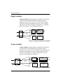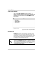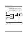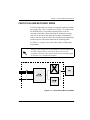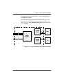
1
MX2800 STS-1
User Manual
4200659L1
61200659L1-1A
January 2001
AC Non-Redundant Version with Modem
4200659L2
AC Redundant Version with Modem
4200659L3
DC Non-Redundant Version with Modem
4200659L4
DC Redundant Version with Modem
4200659L5
AC Non-Redundant Version
4200659L6
AC Redundant Version
4200659L7
DC Non-Redundant Version
4200659L8
DC Redundant Version
1200291L1
Breakout Panel
4175043L2
Battery Backup
1200657L2
Battery Backup Adapter Cable
1200287L1
Amp to Punch-Down Cable
Trademark Information
OpenView is a trademark of Hewlett-Packard Company.
Spectrum is a registered trademark of Cabletron.
901 Explorer Boulevard
P.O. Box 140000
Huntsville, AL 35814-4000
Phone: (256) 963-8000
© 2001 ADTRAN, Inc.
All rights reserved.
Printed in USA.
FCC regulations require that the following information be provided in this manual:
1. This equipment complies with Part 68 of FCC rules. On the bottom of the equipment housing is a label showing the FCC registration number and ringer equivalence number (REN). If requested, provide this information to the telephone
company.
2. If this equipment causes harm to the telephone network, the telephone company
may temporarily discontinue service. If possible, advance notification is given;
otherwise, notification is given as soon as possible. The telephone company will
advise the customer of the right to file a complaint with the FCC.
3. The telephone company may make changes in its facilities, equipment, operations,
or procedures that could affect the proper operation of this equipment. Advance
notification and the opportunity to maintain uninterrupted service are given.
4. If experiencing difficulty with this equipment, please contact ADTRAN for repair
and warranty information. The telephone company may require this equipment to
be disconnected from the network until the problem is corrected or it is certain the
equipment is not malfunctioning.
5. This unit contains no user-serviceable parts.
6. An FCC compliant telephone cord with a modular plug is provided with this
equipment. This equipment is designed to be connected to the telephone network
or premises wiring using an FCC compatible modular jack, which is Part 68 compliant.
7. The following information may be required when applying to the local telephone
company for a dial-up line for the V.34 modem:
Service Type
REN
FIC
USOC
Loop Start
1.6B/0.8A
02LS2
RJ-11C
8. The REN is useful in determining the quantity of devices you may connect to your
telephone line and still have all of those devices ring when your number is called.
In most areas, the sum of the RENs of all devices should not exceed five. To be
certain of the number of devices you may connect to your line as determined by
the REN, call your telephone company to determine the maximum REN for your
calling area.
9. This equipment may not be used on coin service provided by the telephone company. Connection to party lines is subject to state tariffs. Contact your state public utility commission or corporation commission for information.
61200659L1-1
MX2800 STS-1 User Manual
iii
Federal Communications Commission
Radio Frequency Interference Statement
This equipment has been tested and found to comply with the limits for a Class A digital device, pursuant to Part 15 of the FCC Rules. These limits are designed to provide
reasonable protection against harmful interference when the equipment is operated in
a commercial environment. This equipment generates, uses, and can radiate radio frequency energy and, if not installed and used in accordance with the instruction manual, may cause harmful interference to radio frequencies. Operation of this equipment
in a residential area is likely to cause harmful interference in which case the user will
be required to correct the interference at his own expense
.
Shielded cables must be used with this unit to ensure compliance with
Class A FCC limits.
Changes or modifications to this unit not expressly approved by
the party responsible for compliance could void the user's
authority to operate the equipment.
Canadian Emissions Requirements
This digital apparatus does not exceed the Class A limits for radio noise emissions
from digital apparatus as set out in the interference-causing equipment standard entitled “Digital Apparatus,” ICES-003 of the Department of Communications.
Cet appareil nuerique respecte les limites de bruits radioelectriques applicables aux
appareils numeriques de Class A prescrites dans la norme sur le materiel brouilleur:
“Appareils Numeriques,” NMB-003 edictee par le ministre des Communications.
iv
MX2800 STS-1 User Manual
61200659L1-1
Canadian Equipment Limitations
Notice: The Canadian Industry and Science Canada label identifies certified equipment. This certification means that the equipment meets certain telecommunications
network protective, operational, and safety requirements. The Department does not
guarantee the equipment will operate to the user’s satisfaction.
Before installing this equipment, users should ensure that it is permissible to be connected to the facilities of the local telecommunications company. The equipment must
also be installed using an acceptable method of connection. In some cases, the company’s inside wiring associated with a single line individual service may be extended
by means of a certified connector assembly (telephone extension cord). The customer
should be aware that compliance with the above limitations may not prevent degradation of service in some situations.
Repairs to certified equipment should be made by an authorized Canadian maintenance facility designated by the supplier. Any repairs or alterations made by the user
to this equipment, or equipment malfunctions, may give the telecommunications company cause to request the user to disconnect the equipment.
Users should ensure for their own protection that the electrical ground connections of
the power utility, telephone lines and internal metallic water pipe system, if present,
are connected together. This precaution may be particularly important in rural areas.
Users should not attempt to make such connections themselves, but
should contract the appropriate electric inspection authority, or an
electrician, as appropriate.
The Load Number (LN) assigned to each terminal device denotes the percentage of
the total load to be connected to a telephone loop which is used by the device, to prevent overloading. The termination on a loop may consist of any combination of
devices subject only to the requirement that the total of the Load Numbers of all
devices does not exceed 100.
61200659L1-1
MX2800 STS-1 User Manual
v
Important Safety Instructions
Save These Instructions
When using your telephone equipment, please follow these basic safety precautions to
reduce the risk of fire, electrical shock, or personal injury:
1. Do not use this product near water, such as near a bathtub, wash bowl, kitchen
sink, laundry tub, in a wet basement, or near a swimming pool.
2. Avoid using a telephone (other than a cordless-type) during an electrical storm.
There is a remote risk of shock from lightning.
3. Do not use the telephone to report a gas leak in the vicinity of the leak.
4. Use only the power cord, power supply, and/or batteries indicated in the manual.
Do not dispose of batteries in a fire. They may explode. Check with local codes
for special disposal instructions.
Warranty and Customer Service
ADTRAN will replace or repair this product within ten years from the date of shipment if it does not meet its published specifications or fails while in service. For
detailed warranty, repair, and return information refer to the ADTRAN Equipment
Warranty and Repair and Return Policy Procedure.
Return Material Authorization (RMA) is required prior to returning equipment to
ADTRAN.
For service, RMA requests, or further information, contact one of the numbers listed
at the end of this manual.
vi
MX2800 STS-1 User Manual
61200659L1-1
LIMITED PRODUCT WARRANTY
ADTRAN warrants that for ten (10) years from the date of shipment to Customer, all
products manufactured by ADTRAN will be free from defects in materials and workmanship. ADTRAN also warrants that products will conform to the applicable specifications and drawings for such products, as contained in the Product Manual or in
ADTRAN's internal specifications and drawings for such products (which may or may
not be reflected in the Product Manual). This warranty only applies if Customer gives
ADTRAN written notice of defects during the warranty period. Upon such notice,
ADTRAN will, at its option, either repair or replace the defective item. If ADTRAN
is unable, in a reasonable time, to repair or replace any equipment to a condition as
warranted, Customer is entitled to a full refund of the purchase price upon return of
the equipment to ADTRAN. This warranty applies only to the original purchaser and
is not transferable without ADTRAN's express written permission. This warranty
becomes null and void if Customer modifies or alters the equipment in any way, other
than as specifically authorized by ADTRAN.
EXCEPT FOR THE LIMITED WARRANTY DESCRIBED ABOVE, THE FOREGOING CONSTITUTES THE SOLE AND EXCLUSIVE REMEDY OF THE CUSTOMER AND THE EXCLUSIVE LIABILITY OF ADTRAN AND IS IN LIEU OF
ANY AND ALL OTHER WARRANTIES (EXPRESSED OR IMPLIED). ADTRAN
SPECIFICALLY DISCLAIMS ALL OTHER WARRANTIES, INCLUDING (WITHOUT LIMITATION), ALL WARRANTIES OF MERCHANTABILITY AND FITNESS FOR A PARTICULAR PURPOSE. SOME STATES DO NOT ALLOW THE
EXCLUSION OF IMPLIED WARRANTIES, SO THIS EXCLUSION MAY NOT
APPLY TO CUSTOMER.
In no event will ADTRAN or its suppliers be liable to Customer for any incidental,
special, punitive, exemplary or consequential damages experienced by either
Customer or a third party (including, but not limited to, loss of data or information,
loss of profits, or loss of use). ADTRAN is not liable for damages for any cause
whatsoever (whether based in contract, tort, or otherwise) in excess of the amount
paid for the item. Some states do not allow the limitation or exclusion of liability for
incidental or consequential damages, so the above limitation or exclusion may not
apply to Customer.
61200659L1-1
MX2800 STS-1 User Manual
vii
Customer Service, Product Support Information, and Training
ADTRAN will replace or repair this product within five years from the date of shipment if the product does not meet its published specification, or if it fails while in service.
A return material authorization (RMA) is required prior to returning equipment to
ADTRAN. For service, RMA requests, training, or more information, see the toll-free
contact numbers given below.
Presales Inquiries and Applications Support
Please contact your local distributor, ADTRAN Applications Engineering, or
ADTRAN Sales:
Applications
Engineering
(800) 615-1176
Sales
(800) 827-0807
Post-Sale Support
Please contact your local distributor first. If your local distributor cannot help, please
contact ADTRAN Technical Support and have the unit serial number available.
Technical Support
(888) 4ADTRAN
The Custom Extended Services (ACES) program offers multiple types and levels of
service plans which allow you to choose the kind of assistance you need. For questions,
call the ACES Help Desk.
ACES Help Desk
viii
(888) 874-2237
MX2800 STS-1 User Manual
61200659L1-1
Repair and Return
If ADTRAN Technical Support determines that a repair is needed, Technical Support
will coordinate with the Custom and Product Service (CAPS) department to issue an
RMA number. For information regarding equipment currently in house or possible
fees associated with repair, contact CAPS directly at the following number:Identify the
CAPS Department
(256) 963-8722
RMA number clearly on the package (below address), and return to the following address:
ADTRAN Customer and Product Service
6767 Old Madison Pike
Building #6 Suite 690
Huntsville, Alabama 35807
RMA # _____________
Training
The Enterprise Network (EN) Technical Training offers training on our most popular
products. These courses include overviews on product features and functions while covering applications of ADTRAN's product lines. ADTRAN provides a variety of training
options, including customized training and courses taught at our facilities or at your site.
For more information about training, please contact your Territory Manager or the Enterprise Training Coordinator.
61200659L1-1
Training - phone
(800) 615-1176, ext. 7500
Training - fax
(256) 963 7941
Training - email
[email protected]
MX2800 STS-1 User Manual
ix
x
MX2800 STS-1 User Manual
61200659L1-1
Table of Contents
List of Figures ........................................................................................................................ xix
List of Tables ......................................................................................................................... xxi
Chapter 1. Introduction
Product Overview .................................................................................................................. 1-1
Controller Card 1:1 Redundancy ..................................................................................... 1-2
STS-1 Overview ..................................................................................................................... 1-3
STS-1 Framing................................................................................................................. 1-3
STS-1 Pointers ................................................................................................................. 1-3
Transport Overhead (TOH) ............................................................................................. 1-4
STS-1 Synchronous Payload Envelope (SPE)................................................................. 1-4
Virtual Tributaries (VT)................................................................................................... 1-4
Unit Timing...................................................................................................................... 1-5
SNMP ..................................................................................................................................... 1-5
Network Manager ........................................................................................................... 1-6
Agent ............................................................................................................................... 1-6
MIB ................................................................................................................................. 1-6
Telnet ..................................................................................................................................... 1-6
TL1 ......................................................................................................................................... 1-7
Available Options .................................................................................................................. 1-8
Breakout Panel (P/N 1200291L1).................................................................................... 1-8
Battery Backup (P/N 4175043L2) ................................................................................... 1-8
Chapter 2. Installation and Operation
Unpack, Inspect, Power Up .................................................................................................... 2-1
Receiving Inspection........................................................................................................ 2-1
ADTRAN Shipments Include .......................................................................................... 2-1
Power Up ......................................................................................................................... 2-2
Rackmount Installation .......................................................................................................... 2-5
Connecting the Breakout Panel........................................................................................ 2-6
Rear Panel .............................................................................................................................. 2-7
LAN Port.......................................................................................................................... 2-8
Modem Port ..................................................................................................................... 2-8
Noncritical and Critical Alarm Connectors ..................................................................... 2-8
Network Interfaces........................................................................................................... 2-9
DSX-1/E1 Interfaces........................................................................................................ 2-9
Power Connection............................................................................................................ 2-9
Front Panel ........................................................................................................................... 2-10
61200659L1-1
MX2800 STS-1 User Manual
xi
Table of Contents
Craft Port........................................................................................................................ 2-10
Establishing Terminal Connection ......................................................................... 2-10
Navigating Within the Menus ................................................................................ 2-11
Status .............................................................................................................. 2-12
Statistics .......................................................................................................... 2-12
Configuration .................................................................................................. 2-12
Diagnostics ..................................................................................................... 2-12
Logout ............................................................................................................. 2-12
ACO Buttons.................................................................................................................. 2-12
LED Descriptions........................................................................................................... 2-13
Power Supply A/B ................................................................................................. 2-13
Status LEDs ........................................................................................................... 2-13
T1/E1 Status LEDs ................................................................................................ 2-15
Chapter 3. Configuration
Network Interface ................................................................................................................... 3-3
STS-1 Configuration ........................................................................................................ 3-3
Line Length .............................................................................................................. 3-3
Timing ...................................................................................................................... 3-3
XCV Threshold ........................................................................................................ 3-4
VT Mode .................................................................................................................. 3-5
Protection Configuration.................................................................................................. 3-5
Active Controller ..................................................................................................... 3-5
Network Protection .................................................................................................. 3-6
Max. Switch Threshold ............................................................................................ 3-6
Min. Switching Period ............................................................................................. 3-6
Miscellaneous................................................................................................................... 3-6
Loopback Timeout ................................................................................................... 3-6
External Clock Configuration .................................................................................. 3-7
VT Interface ........................................................................................................................... 3-7
VT Interface #1-28........................................................................................................... 3-8
VT/Port Mapping ..................................................................................................... 3-8
T1 State .................................................................................................................... 3-8
T1 Coding ................................................................................................................ 3-8
T1 Line Length ........................................................................................................ 3-9
T1 Remote Loopback ............................................................................................... 3-9
T1 Circuit Protection ............................................................................................... 3-9
Hairpin Loopback .................................................................................................... 3-9
Line ID ..................................................................................................................... 3-9
Set Multiple...................................................................................................................... 3-9
Set Cross-Connect Mapping .......................................................................................... 3-10
xii
MX2800 STS-1 User Manual
61200659L1-1
Table of Contents
Restore Defaults ..................................................................................................... 3-11
Restore VT Mapping Defaults ....................................................................................... 3-11
Protection Threshold (1-28)........................................................................................... 3-11
XCV Threshold.............................................................................................................. 3-12
System Management ............................................................................................................ 3-13
Management Options ..................................................................................................... 3-14
Local IP Address .................................................................................................... 3-14
Gateway IP Address .............................................................................................. 3-14
Subnet Mask .......................................................................................................... 3-14
Management Port ................................................................................................... 3-14
Dialup Options ....................................................................................................... 3-14
Primary and Secondary Phone Numbers ........................................................ 3-15
Initializing String ............................................................................................ 3-15
Dial String ...................................................................................................... 3-15
Maximum Redial Attempts ............................................................................ 3-15
Idle Timeout ................................................................................................... 3-16
Connection Timeout ....................................................................................... 3-16
Pause Between Calls ....................................................................................... 3-16
Dialout On Trap .............................................................................................. 3-16
Answer on Ring .............................................................................................. 3-16
Modem Mode ................................................................................................. 3-17
Modem Baud Rate .......................................................................................... 3-17
Hangup ........................................................................................................... 3-17
Last Modem Response ................................................................................... 3-17
Alarm Relays ................................................................................................................. 3-18
Alarm Relay Configuration ................................................................................... 3-18
STS-1 Alarms ................................................................................................. 3-19
VT/Port Alarms .............................................................................................. 3-21
System Alarms ................................................................................................ 3-23
Power Supply Alarms ..................................................................................... 3-24
SNMP Management Options ......................................................................................... 3-25
Trap IP Addresses .................................................................................................. 3-25
Trap Generation ..................................................................................................... 3-25
STS-1 Active Alarm Traps ............................................................................. 3-26
STS-1 Standby Alarm Traps .......................................................................... 3-28
VT/Port Traps ................................................................................................. 3-30
System Traps .................................................................................................. 3-31
Power Supply Alarm Traps ............................................................................ 3-33
MIB II Standard Alarm Traps ........................................................................ 3-34
Read Community Name ........................................................................................ 3-34
Write Community Name ........................................................................................ 3-34
61200659L1-1
MX2800 STS-1 User Manual
xiii
Table of Contents
Trap Community Name ......................................................................................... 3-34
System Security.............................................................................................................. 3-35
Password ................................................................................................................ 3-35
Terminal Timeout .................................................................................................. 3-35
IP Security .............................................................................................................. 3-35
IP Hosts .................................................................................................................. 3-35
Date & Time................................................................................................................... 3-35
Miscellaneous................................................................................................................. 3-36
Equipment Identification ....................................................................................... 3-36
Unit ID ............................................................................................................ 3-36
STS-1 J1 Path Trace ....................................................................................... 3-36
Syslog Setup .......................................................................................................... 3-36
Transmission ................................................................................................... 3-36
Host IP Address .............................................................................................. 3-36
Severity Level ................................................................................................. 3-36
Host Facility ................................................................................................... 3-37
TL1 Account Management .................................................................................... 3-37
Save on Logout ...................................................................................................... 3-38
Craft baud rate ....................................................................................................... 3-38
Utilities ................................................................................................................................. 3-38
Load Default Settings..................................................................................................... 3-40
Update FLASH Software ............................................................................................... 3-40
Update Via XMODEM .......................................................................................... 3-40
Update via TFTP Server ........................................................................................ 3-41
Config Transfer .............................................................................................................. 3-41
Saving to a TFTP Server ........................................................................................ 3-41
Retrieving from a TFTP Server ............................................................................. 3-42
System Reset .................................................................................................................. 3-43
Save Configuration ............................................................................................................... 3-43
Chapter 4. Status
STS-1 State ............................................................................................................................. 4-2
Card A .............................................................................................................................. 4-2
Card A/Card B Alarms..................................................................................................... 4-2
Network Port Mapping..................................................................................................... 4-4
Power Supply State ................................................................................................................ 4-5
System State ........................................................................................................................... 4-5
Alarm ............................................................................................................................... 4-5
Card A/Card B ................................................................................................................. 4-6
Protection ......................................................................................................................... 4-7
Card Comm ...................................................................................................................... 4-7
xiv
MX2800 STS-1 User Manual
61200659L1-1
Table of Contents
Timing Status ......................................................................................................................... 4-8
Clock Status ..................................................................................................................... 4-8
Current Source ................................................................................................................. 4-8
PRI Ext. Clock ................................................................................................................. 4-9
SEC Ext. Clock ................................................................................................................ 4-9
VT/Port State ........................................................................................................................ 4-10
VT/Port State ................................................................................................................ 4-10
Acknowledge Alarms (ACO) ............................................................................................... 4-12
Chapter 5. Statistics
STS-1 Statistics ...................................................................................................................... 5-2
24 Hour Alarm History .................................................................................................... 5-2
Performance Parameters .................................................................................................. 5-6
Interval starting at: ................................................................................................... 5-7
Severely Errored Framing Seconds (SEFS) ............................................................ 5-7
Section Coding Violations (SCV) ........................................................................... 5-7
Line Coding Violations (LCV) ................................................................................ 5-7
Path Coding Violations (PCV) ................................................................................ 5-7
Section Errored Seconds (SES) ............................................................................... 5-8
Line Errored Seconds (LES) .................................................................................... 5-8
Path Errored Seconds (PES) .................................................................................... 5-8
Section Severely Errored Seconds (SSES) .............................................................. 5-8
Line Severely Errored Seconds (LSES) .................................................................. 5-8
Path Severely Errored Seconds (PSES) ................................................................... 5-8
Line Unavailable Seconds (LUAS) ......................................................................... 5-9
Path Unavailable Seconds (PUAS) .......................................................................... 5-9
Clear All Local STS-1 Statistics .............................................................................. 5-9
Local VT Statistics ................................................................................................................. 5-9
Alarm History ................................................................................................................ 5-10
Performance Parameters ................................................................................................ 5-12
Local Port Statistics ............................................................................................................. 5-15
Loss of Signal Alarms ................................................................................................... 5-15
Bipolar Violation Counts .............................................................................................. 5-15
AIS Loop Alarms .......................................................................................................... 5-15
AIS Carrier Alarms ....................................................................................................... 5-16
Far End STS-1 Statistics ...................................................................................................... 5-16
Performance Parameters ................................................................................................ 5-16
Interval starting at: ................................................................................................. 5-18
Severely Errored Framing Seconds (SEFS) .......................................................... 5-18
Section Coding Violations (SCV) ......................................................................... 5-18
Line Coding Violations (LCV) .............................................................................. 5-18
61200659L1-1
MX2800 STS-1 User Manual
xv
Table of Contents
Path Coding Violations (PCV) .............................................................................. 5-18
Section Errored Seconds (SES) ............................................................................. 5-19
Line Errored Seconds (LES) .................................................................................. 5-19
Path Errored Seconds (PES) .................................................................................. 5-19
Section Severely Errored Seconds (SSES) ............................................................ 5-19
Line Severely Errored Seconds (LSES) ................................................................. 5-19
Path Severely Errored Seconds (PSES) ................................................................. 5-19
Line Unavailable Seconds (LUAS) ....................................................................... 5-20
Path Unavailable Seconds (PUAS) ........................................................................ 5-20
Clear All Far End STS-1 Statistics ........................................................................ 5-20
Chapter 6. Diagnostics
VT/Port Loopbacks ................................................................................................................ 6-2
Tributary........................................................................................................................... 6-2
Analog Network ............................................................................................................... 6-3
Digital Line/Net ............................................................................................................... 6-4
Codec Line/Net ................................................................................................................ 6-4
CSU Loopback ................................................................................................................. 6-5
CSU Loopback w/BERT.................................................................................................. 6-5
VT BERT ......................................................................................................................... 6-6
Line BERT ....................................................................................................................... 6-7
STS-1 Loopbacks ................................................................................................................... 6-8
Line Network ................................................................................................................... 6-8
Analog Loopback ............................................................................................................. 6-9
Digital Loopback............................................................................................................ 6-10
Metallic Diagnostics ...................................................................................................... 6-11
Chapter 7. Circuit and Network Redundancy
Non-Redundant Mode ............................................................................................................ 7-2
Circuit Failure Recovery Mode .............................................................................................. 7-3
Circuit and Network Failure Recovery Mode ........................................................................ 7-4
Chapter 8. Power Loss Recovery
Non-Redundant Power Mode ................................................................................................. 8-2
Power Supply Recovery Mode ............................................................................................... 8-3
Power Supply and Source Recovery Mode ............................................................................ 8-4
Battery Backup Mode ............................................................................................................. 8-5
Chapter 9. Transaction Language 1 (TL1)
Introduction ............................................................................................................................ 9-1
Overview ................................................................................................................................ 9-1
xvi
MX2800 STS-1 User Manual
61200659L1-1
Table of Contents
TL1 Messages ........................................................................................................................ 9-2
TL1 Responses................................................................................................................. 9-2
Acknowledgment Messages .................................................................................... 9-2
In Progress ........................................................................................................ 9-3
All Right ........................................................................................................... 9-3
Output Response Messages ..................................................................................... 9-3
Autonomous Messages ............................................................................................ 9-4
TL1 Commands ...................................................................................................................... 9-5
TL1 Autonomous Messages ................................................................................................. 9-10
TL1 Error Codes .................................................................................................................. 9-13
Appendix A. Pinouts .......................................................................................................... A-1
Appendix B. Specifications Summary ............................................................................... B-1
Appendix C. Acronyms/Abbreviations ............................................................................ C-1
Appendix D. Glossary ........................................................................................................ D-1
Index .............................................................................................................................. Index-1
61200659L1-1
MX2800 STS-1 User Manual
xvii
Table of Contents
xviii
MX2800 STS-1 User Manual
61200659L1-1
List of Figures
Figure 2-1.
Figure 2-2.
Figure 2-3.
Figure 2-4.
Figure 2-5.
Figure 3-1.
Figure 3-2.
Figure 3-3.
Figure 3-4.
Figure 3-5.
Figure 3-6.
Figure 3-7.
Figure 3-8.
Figure 3-9.
Figure 3-10.
Figure 3-11.
Figure 3-12.
Figure 3-13.
Figure 4-1.
Figure 5-1.
Figure 5-2.
Figure 5-3.
Figure 5-4.
Figure 5-5.
Figure 5-6.
Figure 5-7.
Figure 5-8.
Figure 5-9.
Figure 5-10.
Figure 5-11.
Figure 5-12.
Figure 5-13.
DC Power Connector......................................................................................... 2-3
The Breakout Panel ........................................................................................... 2-6
MX2800 STS-1 Rear View ............................................................................... 2-7
MX2800 STS-1 Front Panel............................................................................ 2-10
Terminal Main Menu ....................................................................................... 2-11
Configuration Menu .......................................................................................... 3-1
Configuration Menu Tree .................................................................................. 3-2
Network Configuration Menu ........................................................................... 3-3
VT Interface Menu ............................................................................................ 3-7
Configure VT Interface #1 Menu ...................................................................... 3-8
Set Multiple Menu ........................................................................................... 3-10
Set Cross-Connect Mapping Menu ................................................................. 3-11
XCV Threshold Menu ..................................................................................... 3-12
System Management Configuration Menu...................................................... 3-13
Dialup Options Menu ...................................................................................... 3-15
Alarm Relay Configuration Menu.................................................................. 3-18
Trap Generation Menu..................................................................................... 3-25
System Utilities Menu ..................................................................................... 3-39
Status Menu ....................................................................................................... 4-1
Statistics Menu .................................................................................................. 5-1
Local STS-1 Statistics Menu ............................................................................. 5-2
Local STS-1 Current Alarm Count Screen........................................................ 5-4
Local STS-1 24-Hour Alarm History Screen .................................................... 5-5
Local STS-1 Performance Parameters (Current 15 Minutes)............................ 5-6
Local STS-1 Performance Parameters (24 Hour History)................................. 5-6
Local STS-1 Performance Parameters (24 Hour Totals) ................................... 5-7
Local VT Statistics ............................................................................................ 5-9
Local VT-LOP Alarm Count Screen (Current 15 Minutes)............................ 5-12
Local VT-LOP Alarm Count Screen (24 Hour History) ................................. 5-12
Local VT-CV Performance Parameters (Current 15 Minutes)........................ 5-14
Local VT-CV Performance Parameters (24 Hour History)............................. 5-14
Local Port Statistics Menu............................................................................... 5-15
List of Figures
Figure 5-14.
Figure 5-15.
Figure 5-16.
Figure 5-17.
Figure 6-1.
Figure 6-2.
Figure 6-3.
Figure 6-4.
Figure 6-5.
Figure 6-6.
Figure 6-7.
Figure 6-8.
Figure 6-9.
Figure 6-10.
Figure 6-11.
Figure 6-12.
Figure 6-13.
Figure 6-14.
Figure 7-1.
Figure 7-2.
Figure 7-3.
Figure 8-1.
Figure 8-2.
Figure 8-3.
Figure 8-4.
xx
Far End STS-1 Statistics Menu ....................................................................... 5-16
Far End STS-1 Performance Parameters (Current 15 Minutes) ...................... 5-17
Far End STS-1 Performance Parameters (24 Hour History) ........................... 5-17
Far End STS-1 Performance Parameters (24 Hour Totals) ............................. 5-18
Diagnostics Menu .............................................................................................. 6-1
VT/Port Diagnostics Menu ................................................................................ 6-2
Tributary Loopback Test.................................................................................... 6-3
Analog Network Loopback................................................................................ 6-3
Digital Line/Network Loopback........................................................................ 6-4
Codec Loopback ................................................................................................ 6-4
Diagnostics Menu with BERT Selected ............................................................ 6-6
VT Bert Test ...................................................................................................... 6-7
Line Bert Test .................................................................................................... 6-7
STS-1 Diagnostics Menu................................................................................... 6-8
Line Network Test ............................................................................................. 6-9
Analog Loopback............................................................................................... 6-9
Digital Loopback ............................................................................................. 6-10
Metallic Diagnostics Loopback Test ............................................................... 6-11
Non-Redundant Mode ....................................................................................... 7-2
Circuit Failure Recovery Mode ......................................................................... 7-3
Circuit and Network Failure Recovery Mode ................................................... 7-5
Non-Redundant Power Mode ............................................................................ 8-2
Power Supply Failure Recovery Mode.............................................................. 8-3
Power Supply and Source Failure Recovery Mode........................................... 8-4
Battery Backup System...................................................................................... 8-5
MX2800 STS-1 User Manual
61200659L1-1
List of Tables
Table 2-1.
Table 2-2.
Table 2-3.
Table 2-4.
Table 3-1.
Table 7-1.
Table 9-1.
Table 9-2.
Table 9-3.
Table 9-4.
Table A-1.
Table A-2.
Table A-3.
Table A-4.
61200659L1-1
DC Connector Symbol Definitions ................................................................... 2-3
LED Conditions for Active Cards .................................................................. 2-14
LED Conditions for Standby Cards................................................................. 2-15
T1/E1 LED Conditions ................................................................................... 2-16
Syslog Severity Levels .................................................................................. 3-37
Configuration Requirements for Circuit Recovery ........................................... 7-4
TL1 Commands ................................................................................................ 9-6
MX2800 STS-1 Alarm Events ....................................................................... 9-10
MX2800 STS-1 Informational Events ............................................................ 9-12
TL1 Error Codes.............................................................................................. 9-13
Craft Port Pin Assignments .............................................................................. A-1
LAN Port Pin Assignments ............................................................................. A-2
Modem Port Pin Assignments .......................................................................... A-2
Amp Pin Assignments ...................................................................................... A-3
MX2800 STS-1 User Manual
xxi
List of Tables
xxii
MX2800 STS-1 User Manual
61200659L1-1
Chapter 1
Introduction
PRODUCT OVERVIEW
The MX2800 STS-1 is a SONET multiplexer that consolidates T1
and E1 signals into an STS-1 signal. This unit provides a costeffective, versatile tool for combining independent T1s or E1s over
the same STS-1 carrier.
Embedded SNMP (simple network management protocol) and
Telnet are available through the modem port using SLIP/PPP or
through the 10BaseT ethernet port. Using the Management
Information Base II (MIB II), RFC 1595 standards, and an
ADTRAN enterprise MIB, the MX2800 STS-1 can be configured,
monitored, and diagnosed with standard SNMP network
management programs such as Hewlett Packard’s HP OpenView™
and Cabletron’s Spectrum™. In addition, the SysLog Host Daemon
allows remote monitoring, collecting, and logging of MX2800
STS-1 events in real time. This information can be useful during
installation setups and/or troubleshooting.
Complete configuration, diagnostics, and performance monitoring
are available through SNMP, Telnet, or a VT-100 terminal
interface. This connection can be made via ethernet, a local EIA232 link, or through the built-in V.34 modem (see the note at the
end of this section on page 1-2). The modem can dial-out a “cry for
help” for units located in unmanned facilities. The MX2800 STS-1
is designed for either desktop use or for installation in a 19-inch or
23-inch rack.
61200659L1-1
MX2800 STS-1 User Manual
1-1
Chapter 1. Introduction
The major features of the MX2800 STS-1 are as follows:
•
•
•
•
•
•
•
•
•
•
•
•
•
Built-in 1:1 redundancy
Hot-swappable controller cards
Independent, dual-load sharing, redundant power supplies
Embedded SNMP and Telnet management through 10BaseT
ethernet or SLIP/PPP dialup
Detailed performance monitoring for local and remote units
Simplified configuration through the VT-100 terminal menu
structure
Integrated V.34 modem for dial-up and dial-out access (see the
following note)
Capable of backhauling multiple service types (T1/E1)
AC or DC power
VT Hairpining
VT cross-connect to any DS1
NEBS Level 3 compliant
Standard 10-year warranty
Information regarding the built-in modem applies to the following
list of part numbers: 4200659L1, L2, L3, and L4.
Controller Card 1:1 Redundancy
The MX2800 STS-1 supports two hot-swappable controller cards
which provide 1:1 redundancy for the T1 and STS-1 signals as well
as the STS-1 connections. With two cards installed, the MX2800
STS-1 can recover from circuit or network failure, depending on
the configuration. See Chapter 7, Circuit and Network Redundancy
for more information.
1-2
MX2800 STS-1 User Manual
61200659L1-1
Chapter 1. Introduction
STS-1 OVERVIEW
The MX2800 STS-1 multiplexer delivers up to 28 T1s or 21 E1s via
the SONET Synchronous Transport Signal Level One (STS-1) at a
speed of 51.84 Mbps. This is a cost-effective way to provide T1/E1
signals without the need for costly and complex multi-level
multiplexing/demultiplexing as in an M13 multiplexer. The T1/E1
signals can be directly multiplexed into the SONET STS-1 signal,
allowing simplified add and drop functionality.
The MX2800 STS-1 multiplexer also implements VT hairpining
and VT cross-connect mapping. Any VT can be hairpinned back to
the STS-1 signal for dropping further down the SONET ring.
Cross-connect mapping permits a VT to be mapped to any of the 28
available physical ports.
STS-1 Framing
The STS-1 frame is organized as 9 rows by 90 columns of bytes.
This frame is transmitted row by row, from left to right, and with
the most significant bit (MSB) of each byte transmitted first. It is
defined to operate at the basic rate of 8 kHz or 125 microseconds
per frame, or 8,000 frames per second at a bit rate of 51.84 Mbps.
The frame is divided into two parts to physically segregate the
layers. The first 3 columns make up the transport overhead (TOH);
the remainder is the synchronous payload envelope (SPE). The
TOH has 3 rows for the section overhead (SOH) and 6 rows for the
line overhead (LOH). The SPE has one column for the path
overhead (POH). The remaining 86 columns are for payload data
(49.536 Mbps).
STS-1 Pointers
There are several mechanisms that allow for timing compensation
between the STS-1 and its low speed tributaries. The MX2800
STS-1 multiplexer uses pointer adjustments to achieve timing
61200659L1-1
MX2800 STS-1 User Manual
1-3
Chapter 1. Introduction
compensation. Pointer adjustments allow the synchronous payload
envelope (SPE) to float with respect to the SONET frame. The
pointer is contained in the H1 and H2 bytes of the line overhead
(LOH), and is a count of the number of bytes the J1 byte is away
from the H3 byte, not including the transport overhead. When
timing differences exist, dummy bytes are inserted into the SPE
without affecting data. The receiving end can recover the payload
since the pointer is adjusted to indicate where the payload overhead
(POH) starts.
Transport Overhead (TOH)
The first three columns are the TOH, which contains the overhead
bytes for the Section and Line layers. Section overhead is
comprised of 9 bytes and Line overhead is comprised of 18 bytes.
STS-1 Synchronous Payload Envelope (SPE)
The SPE has 87 columns and 9 rows of bytes for a total of 783
bytes. Column 1 contains the STS Path Overhead and has 9 bytes.
The remaining 774 bytes are available for payload.
Virtual Tributaries (VT)
The SPE is divided into seven virtual tributary groups, made up of
12 columns each. Smaller tributaries are multiplexed together to
form these groups. For example, there can be four VT1.5 tributaries
in a VT group or three VT2 tributaries. A VT1.5 tributary consists
of three columns per STS-1 frame and has a bit rate of 1.728 Mbps,
allowing transport of a T1 at 1.544 Mbps plus required overhead. A
VT2 uses four columns per STS-1 frame and has a bit rate of 2.304
Mbps, allowing transport of an E1 at 2.048 Mbps plus required
overhead.
1-4
MX2800 STS-1 User Manual
61200659L1-1
Chapter 1. Introduction
Unit Timing
The MX2800 STS-1 multiplexer allows three timing methods. The
first is LOOP timed, in which the multiplexer derives timing from
the incoming STS-1 signal. A failure in this signal, such as a lossof-signal (LOS) or a loss-of-framing (LOF) will cause the unit to
enter HOLDOVER (HO) mode for the duration of the receive signal
defect. During HO, the unit will continue transmitting at the same
rate as the receive signal prior to entering its defect condition.
Stability of the transmit during HO is guaranteed to +/- 4.9 ppm
over 24 hours. The defect condition must be cleared before LOOP
time mode can be resumed.
The second mode of operation is FREE-RUNNING (FR) mode. In this
mode, an internal oscillator is used to generate transmit timing.
FREE-RUNNING mode provides a SONET minimum clock
specification of +/- 20 ppm.
The third timing operation mode is EXTERNAL. EXTERNAL timing
mode allows the MX2800 STS-1 to derive its transmit timing from
any one of the 28 DSX-1/E1 physical ports. The ports selected may
be data carrying ports. Two sources can be specified to provide
external timing: a primary and a secondary source. Failure of the
primary source (due to LOS or AIS) will cause the unit to switch to
the secondary source, if available. In the event that both the primary
and secondary sources are lost, the unit will enter HOLDOVER mode
as described previously. Holdover mode will be exited upon
recovery of at least one clock source.
SNMP
The MX2800 STS-1's embedded SNMP feature allows the unit to
be accessed and controlled by a network manager through the
10BaseT local area network (LAN) port. The MX2800 STS-1
61200659L1-1
MX2800 STS-1 User Manual
1-5
Chapter 1. Introduction
supports the MIB-II standard, RFC 1213, RFC 1595, and the
ADTRAN Enterprise Specific MIB.
MIB files are available at www.adtran.com.
The term SNMP broadly refers to the message protocols used to
exchange information between the network management system
(NMS) and the managed devices, as well as to the structure of
device management databases. SNMP has three basic components,
the network manager, the agent, and the MIB.
Network Manager
The network manager is a set of control programs that collect,
control, and present data pertinent to the operation of the network
devices. These programs reside on a network management station.
Agent
The agent is a control program that resides in every network device.
This program responds to queries and commands from the network
manager, returns requested information or invokes configuration
changes initiated by the manager, and sends unsolicited traps to the
manager.
MIB
A MIB is an industry standard presentation of all status and
configuration parameters supported by a network device.
TELNET
Telnet provides a password-protected, remote login facility to the
MX2800 STS-1 that allows a remote user to control the MX2800
STS-1 through the terminal menus. Only one Telnet session may be
active at a time.
1-6
MX2800 STS-1 User Manual
61200659L1-1
Chapter 1. Introduction
TL1
Transaction Language 1 (TL1) is an ASCII based language that
supports both command-response and autonomous (NE) message
generation. Commonly, TL1 is used over a X.25 packet network
but is completely independent of any physical layer protocols. For
the MX2800 STS-1, TL1 is implemented as a Telnet session
running over either Ethernet or PPP. Only one TL1 Telnet
connection can be active at a time.
61200659L1-1
MX2800 STS-1 User Manual
1-7
Chapter 1. Introduction
AVAILABLE OPTIONS
The following optional equipment is available for use with the
MX2800 STS-1. Contact your local distributor or the ADTRAN
sales department for more information (see front section of this
manual for phone number).
Breakout Panel (P/N 1200291L1)
The optional breakout panel connects to the MX2800 STS-1 and
provides 28 RJ connectors for the individual T1s/E1s. Shipment
includes two six-foot, 64-pin to 64-pin Amp cables which allow
direct cabling to the MX2800 STS-1 (see Connecting the Breakout
Panel on page 2-6 for more information).
Battery Backup (P/N 4175043L2)
The battery backup system provides power backup in the event of
power loss. This system includes the battery, an AC battery
charger, and an alarm cable.
1-8
MX2800 STS-1 User Manual
61200659L1-1
Chapter 2
Installation and Operation
UNPACK, INSPECT, POWER UP
Receiving Inspection
Carefully inspect the MX2800 STS-1 for any damage that might
have occurred in shipment. If damage is suspected, file a claim
immediately with the carrier and contact ADTRAN Technical
Support (see the front section of this manual for phone numbers).
Keep the original shipping container to use for future shipment or
verification of damage during shipment.
ADTRAN Shipments Include
The following items are included in shipments of the MX2800
STS-1:
•
•
•
•
•
•
•
•
61200659L1-1
MX2800 STS-1 unit
DC or AC power supply (two power supplies come with the
Redundant versions)
Controller card (two cards come with the Redundant versions)
8-pin to 6-pin modular cable (Modem version only)
8-pin to 8-pin modular cable
8-pin modular to DB-9 female connector
Two 4-position terminal lug connectors
3-position terminal lug connector
MX2800 User Manual
2-1
Chapter 2. Installation and Operation
•
•
•
Six-foot AC power cord (AC Versions only)
Mounting ears and screws for 19-inch or 23-inch rack
installation
User Manual or CD containing the User Manual
The ADTRAN MX2800 STS-1 MIB is available at www.adtran.com.
Power Up
The AC version of the MX2800 STS-1 is provided with a six-foot
power cord, terminated by a three-prong plug which connects to a
grounded 120 VAC power receptacle.
Power to the AC version of the MX2800 STS-1 must be provided from
a grounded 120 VAC, 60 Hz receptacle.
The DC version of the MX2800 STS-1 is provided with two
4-position modular terminal lug connectors. These connectors
make it easier to perform initial wiring and to connect and
disconnect DC power when replacing rackmount units.
For more detailed information on power connections, refer to
Chapter 8, Power Loss Recovery.
Once the modular connector is wired, push it firmly into one of the
rear panel POWER connectors. Figure 2-1 and Table 2-1 on page
2-2
MX2800 User Manual
61200659L1-1
Chapter 2. Installation and Operation
2-3 illustrate the DC power connector and give definitions for the
four connector symbols.
The chassis should be connected to an earth ground using the
ground stud located between the AC and DC power sources on the
rear panel.
NET
PWR
FAIL
PWR
FAIL
PWR
FAIL
Figure 2-1. DC Power Connector
Table 2-1. DC Connector Symbol Definitions
Symbol
Definition
Battery backup connection. If AC fails, a trap is sent to
PWR FAIL alert user when connected to the 4175043L2 battery
backup system or equivalent
-
Negative side of DC power source (usually -48V)
RET
Positive side of DC power source (usually ground)
Frame Ground
61200659L1-1
MX2800 User Manual
2-3
Chapter 2. Installation and Operation
The following UL requirements must be met during installation of
the MX2800 STS-1 DC version:
1. Disconnect all power sources prior to servicing (unit may use
multiple power sources).
2. Input: Minimum 48 VDC, 0.8 A
Minimum 120 VAC, 0.32 A
3. Connect to a reliably grounded -48 VDC source which is
electrically isolated from the AC source.
4. The branch circuit overcurrent protection shall be a fuse or
circuit breaker rated minimum 48 VDC, maximum 20 A.
5. A readily accessible disconnect device that is suitably approved
and rated, shall be incorporated in the field wiring.
6. The chassis should be connected to an earth ground using the
ground stud located between the AC and DC power sources on
the rear panel.
7. The unit shall be installed in accordance with the requirements
of NEC NFPA 70.
8. The unit shall be installed in accordance with Articles 400 and
364.8 of the National Electrical Code NFPA 70 when installed
outside of a Restricted Access Location (i.e. Central Office,
behind a locked door, or service personnel area only).
9. Care should be taken not to upset the stability of the equipment
rack after installation is complete.
To meet the UL requirements during installation, use copper
conductors only.
2-4
MX2800 User Manual
61200659L1-1
Chapter 2. Installation and Operation
RACKMOUNT INSTALLATION
The MX2800 STS-1 can be mounted into a standard 19-inch or
23-inch equipment rack. Follow these steps to mount your unit into
a rack:
1. Prepare the MX2800 STS-1 mounting ears by scraping the
paint away from the mounting ears’ portion that makes contact
with the rack and the portion where the screw mounts into the
side of the MX2800 STS-1.
2. Install the mounting flanges on each side of the MX2800 STS-1
at one of the three available positions.
Be sure to install the flanges with the screws provided.
3. After the flanges have been installed, position the MX2800
STS-1 at the correct location within the rack and secure the
mounting flanges to the mounting rails of the rack.
4. Make all network, DTE, and power connections to the rear of
the unit. See Power Up on page 2-2 for more information on
making the DC power connection.
5. Using the 8-position modular to DB-9 female connector and the
8-position modular to 8-position modular cable, connect a
VT 100 terminal device to the CRAFT port on the front panel of
the unit.
Two MX2800 STS-1s may be stacked with no spacing between units.
ADTRAN recommends 1U (1.75") of separation above and below the
two stacked units. This spacing allows the unit to dissipate heat. The
design of the MX2800 STS-1 uses the chassis to distribute heat
generated by the unit's internal cards. This design allows the unit to
operate without a cooling fan, which increases its overall reliability.
61200659L1-1
MX2800 User Manual
2-5
Chapter 2. Installation and Operation
Connecting the Breakout Panel
The optional breakout panel (P/N 1200291L1) connects to the
MX2800 STS-1 via the IN and OUT Champ connectors located on
the back of the unit, and provides 28 RJ connectors for the
individual T1s/E1s. Shipment includes two six-foot, 64-pin to
64-pin Amp cables which allow direct cabling to the
MX2800 STS-1. Connect the breakout panel’s IN Champ connector
to the MX2800 STS-1’s IN Champ connector and the breakout
panel’s OUT Champ connector to the MX2800 STS-1’s OUT Champ
connector (see Figure 2-2).
Front View
A
C
T
2
4
6
8
10
12
14
16
18
20
22
24
26
28
1
3
5
7
9
11
13
15
17
19
21
23
25
27
N
E
T
A
L
M
P
R
F
Rear View
IN
OUT
Cable 2
115VAC 50/60HZ
0.8a
NET
L
A
N
A
NO COM NC
M
O
D
E
M
OUT
PWR
FAIL
IN
B
CRITICAL
DC POWER
DSX-1/E1
(OUT)
NONCRITICAL
Cable 1
DSX-1/E1
(IN)
RET
B
PWR
FAIL
RET
A
USE COPPER
CONDUCTORS ONLY!
Figure 2-2. The Breakout Panel
2-6
MX2800 User Manual
61200659L1-1
Chapter 2. Installation and Operation
REAR PANEL
The MX2800 STS-1 rear panel is equipped with a LAN port, a
modem port, two alarm output terminal blocks, two sets of NET
in/out jacks, two Amphenol (Amp) connectors, and DC/AC power
connections. Figure 2-3 illustrates the rear panel and identifies its
equipment. Descriptions for these items follow the figure. Pin
assignments are given in Appendix A, Pinouts.
3
L
A
N
1
M
O
D
E
M
2
115VAC 50/60HZ
0.8a
NET
DC POWER
NONCRITICAL
DSX-1/E1
(OUT)
A
OUT
NO COM NC
4
IN
7
5
PWR
FAIL
RET
B
PWR
FAIL
RET
A
6
DSX-1/E1
(IN)
B
8
USE COPPER
CONDUCTORS ONLY!
CRITICAL
#
1
Item
LAN
Function
10BaseT LAN connection
Note: The LED to the right of this connector illuminates
when the unit is connected to an active ethernet segment.
2
Modem
3
Noncritical/Critical Connections for external audible/visible alarms
4
NET
Network service connections for controller cards A and B
5
DSX-1/E1
64-pin Amp connectors for T1/E1s
6
Power
DC power connection
7
8
Telephone line connection for internal V.34 modem (see
note on page 2-8)
Ground stud
115 VAC 50/60Hz AC power connection
Figure 2-3. MX2800 STS-1 Rear View
61200659L1-1
MX2800 User Manual
2-7
Chapter 2. Installation and Operation
LAN Port
The LAN port is an 8-pin modular connector that provides a
10BaseT ethernet LAN interface. This LAN interface is used for
SNMP and Telnet control.
Connect the LAN port to intra-building wiring only.
Modem Port
The MODEM port is an 8-pin modular jack that provides a telephone
line (POTS) connection for the internal V.34 modem.
The MX2800 STS-1 can be configured as a dial-in host and also as
a dial-out-on-Trap device (meaning the unit dials out to a specified
host to report error conditions).
Information regarding the built-in modem applies to the following list
of numbers: 4200659L1, L2, L3, and L4.
Noncritical and Critical Alarm Connectors
The alarm connectors connect to the three contacts of a Form C
type relay on the main board of the MX2800 STS-1. This relay is
activated any time the MX2800 STS-1 detects an alarm condition
on the STS-1 network interface. Both NC (normally closed) and NO
(normally open) contacts are provided.
Connect alarms to one of the three-position modular terminal lug
connectors (provided). These connectors make it easier to perform
initial wiring and to connect and disconnect alarms when replacing
2-8
MX2800 User Manual
61200659L1-1
Chapter 2. Installation and Operation
rackmount units. Once a modular connector is wired, push it firmly
into the rear panel NONCRITICAL or CRITICAL connector.
The alarm functions can be enabled or disabled through the ALARM
RELAYS section of the CONFIGURATION menu (see the section Alarm
Relays on page 3-18).
Network Interfaces
The network interfaces are full-duplex circuits provided by four
BNC coaxial cable connections (two for each controller card). The
receive data from the network is connected to the RX (IN)
connectors, while the transmit data from the MX2800 STS-1 is
connected to the TX (OUT) connectors.
Network interfaces must be connected using coaxial cables that have
the shields grounded at both ends.
DSX-1/E1 Interfaces
The DSX-1/E1 interfaces are 64-pin Amp connectors. These
interfaces provide Tx and Rx connections between the unit and
equipment such as wire-wrap patch panels, punch-down panels, or
breakout panels.
Connect the DSX-1/E1 interfaces to intra-building wiring only.
Power Connection
The DC and AC power connections are described earlier in this
chapter on page 2-2.
61200659L1-1
MX2800 User Manual
2-9
Chapter 2. Installation and Operation
FRONT PANEL
The MX2800 STS-1 faceplate is shown below in Figure 2-4.
Descriptions of each part of the front panel follow.
A
C
T
N
E
T
A
L
M
P
R
F
Figure 2-4. MX2800 STS-1 Front Panel
Craft Port
The CRAFT port, an 8-pin modular jack, provides connection to a
VT-100 EIA-232 compatible interface using the supplied 8-pin
modular to DB-9 female connector and the 8-pin to 8-pin modular
cable.
Establishing Terminal Connection
To connect the MX2800 STS-1 to a VT-100 terminal, follow the
steps below:
1. Configure the VT-100 terminal for 9600, 19200, 38400, or
57600 baud, 8-bit characters, no parity, and one stop bit (xxxx,
8N1).
2. Using the terminal interface cable adapter provided by
ADTRAN, connect the DTE port of a terminal to the 8-pin
modular jack labeled CRAFT on the MX2800 STS-1 front
panel.
3. Initialize the terminal session.
4. Press Enter repeatedly until the password prompt appears.
5. Enter the password. The factory default password is adtran (all
lower-case). The MAIN MENU appears (see Figure 2-5 on page
2-11).
2-10
MX2800 User Manual
61200659L1-1
Chapter 2. Installation and Operation
6. Make selections by entering the number corresponding to the
chosen parameter. Press ESC on the keyboard to return to the
previous screen. End a terminal session by selecting LOGOUT
from the MAIN MENU or by pressing Ctrl-C at any time.
Figure 2-5. Terminal Main Menu
The letter displayed in the upper left-hand corner of the terminal menu
indicates which controller card is active (A or B).
Navigating Within the Menus
Navigate within the MX2800 STS-1 terminal menus using the
following procedures:
61200659L1-1
If you want to...
Press...
select an item
the number corresponding to your choice,
and then press the Enter key
scroll left and right
within the same
screen
the left and right arrow keys. Additional
screens are available when < or > is displayed in the top portion of the menu
return to the previous
menu
the ESC key
MX2800 User Manual
2-11
Chapter 2. Installation and Operation
If you want to...
Press...
end the terminal
session
Ctrl-C
refresh the display
Ctrl-R
The MX2800 STS-1 MAIN MENU consists of the following sections:
Status
Provides information on the current state of the STS-1, power
supplies, system, and VT/Port lines. For more detailed information,
see Chapter 4, Status.
Statistics
Provides detailed statistical information (both current and
historical) for the STS-1, VT, and Port lines. For more detailed
information, see Chapter 5, Statistics.
Configuration
Sets STS-1 network, VT/Port, and system management parameters.
For more detailed information, see Chapter 3, Configuration.
Diagnostics
Performs loopback tests over the STS-1, VT/Port lines. For more
detailed information, see Chapter 6, Diagnostics.
Logout
The LOGOUT selection ends the terminal session and logs out of the
system. Password entry is required before a new session can begin.
The unit will also logout of a terminal session automatically if the
session remains inactive for a certain period of time. For more
information, see Terminal Timeout on page 3-35.
ACO Buttons
The ACO (alarm cut off) buttons allow you to turn off an active
audible alarm. The buttons are recessed, so you must use a pen or
other pointed instrument to press them. Once you have used an ACO
2-12
MX2800 User Manual
61200659L1-1
Chapter 2. Installation and Operation
button to deactivate an alarm, it remains disabled until the condition
has cleared.
Alarms can also be turned off remotely by using a selection found
in the STATUS menu. See Acknowledge Alarms (ACO) on page 4-12
for more information.
LED Descriptions
The MX2800 STS-1 has LED status indicators for the power
supplies, the STS-1 state, the controller cards, and the individual
T1s/E1s. These LEDs are identified in the following subsections.
Power Supply A/B
The PWR LED is active when the unit is on and receiving full
power. The CHK LED is active when the power supply is failing or
is providing low power and needs to be checked.
Status LEDs
The STATUS LEDs apply to the two controller cards. The LEDs
provided are ACT (active), NET, ALM (alarm), and PRF
(performance). Different conditions are indicated by the state of the
LED (it remains solid, blinks, or alternates colors). The condition
descriptions vary depending on whether the LED represents the
active controller card or the controller card on standby. LED
definitions are for the active cards are provided in Table 2-2 on
page 2-14. LED definitions for T1/E1 cards are provided in Table
2-3 on page 2-15.
61200659L1-1
MX2800 User Manual
2-13
Chapter 2. Installation and Operation
Table 2-2. LED Conditions for Active Cards
ACT
LED State
Card Condition
green solid
Normal (All OK)
green/amber alternating
Normal + Console Open
red solid
Self Test Failed
amber solid
Software Update in Progress
red/amber alternating
Self Test Failed + Console
Open
red blinking
Card Failure
green solid
Normal (All OK)
red blinking
LOS
red solid
LOFM. AIS-P, AIS-L, RFI-L,
RFI-P, LOP, SLM, UEQ
amber solid
In Test (Local)
amber blinking
In Test (Remote)
red/amber alternating
In Test + Alarms
green solid
Normal (No Alarm)
red blinking
Critical Alarm
red solid
Non-Critical Alarm
amber blinking
Critical Alarm Suppressed
(ACO button was pushed)
amber solid
Non-Critical Alarm Suppressed (ACO button was
pushed)
green solid
Normal (All OK)
red flash (once per event)
Single/Burst CV
red blinking
Continuous Code Violations
red solid
XCV Threshold Exceeded
NET
ALM
PRF
2-14
MX2800 User Manual
61200659L1-1
Chapter 2. Installation and Operation
Table 2-3. LED Conditions for Standby Cards
LED State
Card Condition
green blinking
Normal (All OK)
amber solid
Software Update in Progress
red blinking
Self Test Failed
off
Normal (All OK)
red blinking
STS-1 Failure
ALM
off
Normal (No Alarm)
PRF
off
Normal (All OK)
ACT
NET
T1/E1 Status LEDs
These LEDs apply to each individual T1 or E1. Different conditions
are indicated by the state of the LED (its color and whether it
flashes, alternates color, or remains solid). The condition
descriptions vary depending on whether the LEDs represent T1s or
E1s of the active controller card or the controller card on standby.
Table 2-4 on page 2-16 provides LED definitions for the active and
standby cards.
61200659L1-1
MX2800 User Manual
2-15
Chapter 2. Installation and Operation
Table 2-4. T1/E1 LED Conditions
Active
Card
LED State
T1/E1 Condition
green solid
Normal (All OK)
off
Disabled
red blinking
LOS
red flash (once per
event)
Single/Burst CV
red/green alternating
XCV Threshold Exceeded
amber solid
In Test (Local)
amber blinking
In Test (Remote)
red/amber alternating
In Test + Alarm
off
Normal (All OK) or
N/A (in the case of E1 configuration)
red blinking
T1/E1 Failure
Standby
Card
2-16
MX2800 User Manual
61200659L1-1
Chapter 3
Configuration
To configure the MX2800 STS-1, use a 10BaseT ethernet
connection, a SLIP/PPP modem port, or a VT-100 terminal. Figure
3-1 shows the CONFIGURATION menu and Figure 3-2 on page 3-2
shows the menu tree.
Figure 3-1. Configuration Menu
Detailed descriptions of the menu options shown in Figure 3-1 are
given in the following sections.
61200659L1-1
MX2800 STS-1 User Manual
3-1
Chapter 3. Configuration
Line Length
STS-1 Configuration
Timing
XCV Threshold
Network Interface
VT Mode
Protection Configuration
Active Controller
Network Protection
Max Switch Threshold
Miscellaneous
Loopback Timeout
External Clock Configuration
PRI Ext. Clock
VT/Port Mapping>
VT Interface #1-28
VT Interface
Min Switching Period
First
T1 State
Last
T1 Coding
State
T1 Remote Loopbacks
Line Coding
T1 Circuit Protection
T1 Line Length
Hairpin Loopback
Circuit Protection
Line ID
Loopback Detection
Set Multiple
Apply State
Set Cross-Connect Mapping
Apply Line Length
Restore VT Mapping Defaults
Apply Circuit Protection
Protection Threshold
Apply Loopback Protection
XCV Threshold
Local IP Address
Apply All
Gateway IP Address
Subnet Mask
MGMT Options
System
Management Port
Trap IP Address
Dial-up Options
Trap Generation
TL1 Setup
Read Community Name
SNMP MGMT Options
Write Community Name
Management
Trap Community Name
Password
Terminal Timeout
Alarm Relay Configuration
System Security
IP Security
Equipment Identification
Date & Time
IP Hosts
Syslog Setup
Miscellaneous
Save on Logout
Craft baud rate
Utilities
Load Default Settings
Update via XMODEM
Update FLASH Software
Update via TFTP Server
Config Transfer
Server ID
Server Filename
Load and Use
System Reset
Save Configuration
Immediate
Save Config Remotely
Scheduled Reset Time
Figure 3-2. Configuration Menu Tree
3-2
MX2800 STS-1 User Manual
61200659L1-1
Chapter 3. Configuration
NETWORK INTERFACE
Select NETWORK INTERFACE to access the network configuration
parameters (see Figure 3-3). Configure the MX2800 STS-1
network settings to match the STS-1 signal received from the
service provider.
Figure 3-3. Network Configuration Menu
STS-1 Configuration
Use the STS-1 CONFIGURATION selections described below to
configure the STS-1 network settings to match your application.
Line Length
Set the line length to reflect the physical length of the STS-1
network line. Set to LONG if the cabling distance is between
225-450 feet; set to SHORT if the distance is less than 225 feet.
Timing
Selects the source of timing used to derive the transmit signal. The
MX2800 STS-1 has three modes of timing operation: LOOP, FREERUN, and EXTERNAL. LOOP timing configures the unit to recover
clocking from the STS-1 receive signal. Loss of the STS-1 receive
61200659L1-1
MX2800 STS-1 User Manual
3-3
Chapter 3. Configuration
signal or reception of AIS will cause the unit to enter hold-over
mode. The STS-1 receive signal must be valid for at least 10
seconds for the unit to exit hold-over mode and restore loop timing.
When the unit is configured for FREE-RUN timing mode, timing is
derived from a +/-20 ppm internal reference providing a SONET
Minimum Clock (SMC).
Setting the unit to EXTERNAL timing mode configures the unit to
derive clocking from one of the two external sources selected in the
PRI EXT. CLOCK and SEC EXT. CLOCK options. These two entries
select which of the 28 active T1/E1 ports will be used as the
external clock source. The external clock source may be disabled (if
only one source exists, or no external clock sources are desired). A
valid clock source is one on which neither LOS or AIS conditions
exist. The selected T1/E1 may be a data carrying tributary. When
both sources are configured, failure of one source will cause the
unit to switch to the other source (if it is a valid source). Failure of
both sources will cause the unit to enter hold-over mode. At least
one external clock source must be valid for at least 10 seconds for
the unit to exit hold-over mode and restore external clock timing.
Switching between PRImary and SECondary external clock sources
is non-reverting.
XCV Threshold
The XCV THRESHOLD (excessive code violations threshold) sets a
limit on code violations accepted by the unit before it switches
controller cards. If set to DISABLED, code violations will not cause
the unit to switch controller cards. The threshold limits are
described in the following chart:
3-4
MX2800 STS-1 User Manual
61200659L1-1
Chapter 3. Configuration
Setting
The unit switches controller cards if...
1E-3
more than one out of every 1,000 bits received on the
STS-1 contains a code violation.
1E-4
more than one out of every 10,000 bits received on
the STS-1 contains a code violation.
1E-5
more than one out of every 100,000 bits received on
the STS-1 contains a code violation.
1E-6
more than one out of every 1,000,000 bits received on
the STS-1 contains a code violation.
VT Mode
The STS-1 can frame the 7 VT groups as either VT1.5 or VT2.
When set for VT1.5 (T1), all VT groups are set for VT1.5[TU=11]
at 1.728 Mbps and the ports are set for T1 at 1.544 Mbps. When set
for VT2 (E1), all the VT groups are set for VT2[TU-12] at
2.304 Mbps and the ports are set for E1 at 2.048 Mbps. When set
for VT2, the last 7 VTs, VT 22-28, become unavailable. All E1
ports are available for mapping.
Protection Configuration
The MX2800 STS-1 houses two controller cards for 1:1 protection
against hardware failure. The two cards can also provide network
protection, supporting two STS-1 circuits simultaneously. The
selections in this menu allow you to customize the unit’s protection
setup.
Active Controller
This field displays A or B, indicating the active controller card. This
setting can be used to force the controller cards to switch. For
example, if controller card A is active and you select B, a switchover occurs immediately.
61200659L1-1
MX2800 STS-1 User Manual
3-5
Chapter 3. Configuration
Network Protection
Enable or disable the unit’s ability to automatically route
information to the backup STS-1 in the event of a primary STS-1
failure. With NETWORK PROTECTION set to ENABLED, all information
is automatically routed to the backup STS-1 in the event that the
primary STS-1 fails. When NETWORK PROTECTION is set to
DISABLED, the stand-by controller will be used to protect against
failures of the circuitry on the active controller.
When choosing a setting for NETWORK PROTECTION, there are many
cabling and network provisioning issues to consider. For configuration
examples of the different modes of protection, refer to
Chapter 7, Circuit and Network Redundancy.
Max. Switch Threshold
The value entered in this field determines the number of times per
hour the unit is allowed to switch between controller cards. If the
cards switch more than the MAX SWITCH THRESHOLD within one
hour, the unit issues a trap and stops switching cards for the next 24
hours. The default setting is 3 times an hour.
Min. Switching Period
After the unit switches controller cards, the number of seconds
entered in this field must pass before another card switch will be
allowed. The default setting is 10 seconds.
Miscellaneous
Loopback Timeout
Sets the loopback timeout to DISABLED, 1 MIN., 5 MIN., 10 MIN.,
15 MIN., 30 MIN., 45 MIN. or 1 HR.
3-6
MX2800 STS-1 User Manual
61200659L1-1
Chapter 3. Configuration
External Clock Configuration
PRI Ext. Clock and SEC Ext. Clock - When timing is set to
external, these entries allow selection of the primary and secondary
clock source. Any one of the 28 ports, so long as it is active, can be
used. If the selected port does go into AIS or LOS, the selected
clock becomes invalid.
VT INTERFACE
The VT INTERFACE menu (shown in Figure 3-4 on page 3-7) allows
you to activate/deactivate individual T1s and E1s and to set their
line coding, length, loopback detection, circuit protection, and line
ID string. The T1/E1 code violation threshold is also configured
through this menu. Configuration selections are described in the
sections following Figure 3-4 on page 3-7.
A VT group can be divided into either three E1s or four T1s. Therefore,
when dealing with an E1 configuration, some of the fields in the VT
INTERFACE menus do not apply (and therefore display N/A).
Figure 3-4. VT Interface Menu
61200659L1-1
MX2800 STS-1 User Manual
3-7
Chapter 3. Configuration
VT Interface #1-28
The VT Interface menu allows the user to map a Port (T1/E1) to a
VT, activate/deactivate the T1 and E1 mapped to the VT, and to set
the line coding, length, loopback detection, circuit protection, line
ID string, and disable/enable the hairpin loopback. Configuration
selections are described in the section following Figure 3-5.
Figure 3-5. Configure VT Interface #1 Menu
VT/Port Mapping
Map a T1/E1 port to a VT. Any available port (1-28) can be
mapped to a VT. An error will be returned if the port is already
mapped to another VT. Selecting UNEQUIPPED will free the port
from mapping and disable the VT.
T1 State
Set unused T1 lines to DISABLED. Set used T1 lines to ENABLED.
T1 Coding
Set the line code for each individual T1 interface to match the
connected device. The choices available for T1 are AMI and B8ZS.
3-8
MX2800 STS-1 User Manual
61200659L1-1
Chapter 3. Configuration
T1 Line Length
Set the line length for each T1 interface according to the distance
from the MX2800 STS-1 to your DTE device. Set to -7.5 DB if the
attached DTE device only supports DS1 levels.
T1 Remote Loopback
Allows a selected T1 to respond to CSU or NIU loopbacks arriving
from the STS-1 side.
T1 Circuit Protection
T1 Circuit Protection determines which circuit will be allowed to
initiate a protection switch if a failure in the circuitry for that
channel is detected. If a T1 is set to DISABLED, then the failure of the
circuitry of that one channel will not cause a protection switch. If
set to ENABLED, then the failure of a channel could cause a
protection switch to occur (depending on the PROTECTION
THRESHOLD setting).
Hairpin Loopback
Hairpin back the VT to the STS-1 signal for dropping farther down
the SONET ring.
Line ID
Enter user-configurable text strings to name the individual T1 lines.
This field will accept up to 18 alpha-numeric characters, including
spaces and special characters (such as an underbar).
Set Multiple
SET MULTIPLE (see Figure 3-6 on page 3-10) can be used to enable/
disable a contiguous group or all of the VTs at one time. It may also
be used to make multiple changes to the line coding, length, circuit
protection or loopback detection of a contiguous group or all VTs at
one time.
61200659L1-1
MX2800 STS-1 User Manual
3-9
Chapter 3. Configuration
To make changes to all VTs, set FIRST to 1 and LAST to 28. Make
the necessary changes and select APPLY ALL (or select the APPLY
option that corresponds to the change made) before leaving the
menu. To make changes to some of the VTs, set the FIRST and LAST
fields to correspond to the lines you want to change. Select APPLY
ALL (or select the APPLY option that corresponds to the change
made). You can now either leave the menu or continue to enter new
FIRST and LAST numbers for other lines. Remember to apply the
settings following each change.
Figure 3-6. Set Multiple Menu
Set Cross-Connect Mapping
Any VT can be cross-connect mapped to any available T1/E1 port.
Selecting UNEQUIPPED will free the port and disable the VT. The
default mapping for VTs 1-28 is 1-to-1.
3-10
MX2800 STS-1 User Manual
61200659L1-1
Chapter 3. Configuration
Figure 3-7. Set Cross-Connect Mapping Menu
Restore Defaults
Restores VT mapping to 1-to-1 mapping.
Restore VT Mapping Defaults
Select RESTORE VT MAPPING DEFAULTS from the VT INTERFACE
configuration menu. The following message will display on the
screen: !WARNING! RESTORING DEFAULTS WILL DISRUPT TRAFFIC.
Select CONFIRM to continue or press Esc to abort.
Protection Threshold (1-28)
The PROTECTION THRESHOLD setting determines how many of the
ENABLED lines must fail before a card switch occurs. If you want the
failure of a single protected (enabled) line to cause a card switch,
set the PROTECTION THRESHOLD to 1. Choices include 1 through 28.
61200659L1-1
MX2800 STS-1 User Manual
3-11
Chapter 3. Configuration
XCV Threshold
Set a limit on code violations (CVs) accepted by the unit over an
individual T1/E1 line before it switches controller cards (see Figure
3-8). If set to DISABLED, code violations will not cause the unit to
switch controller cards. The threshold limits are described in the
following chart:
Setting
The unit switches controller cards if...
1E-3
more than one out of every 1,000 bits received on a
T1/E1 line contains a code violation
1E-4
more than one out of every 10,000 bits received on a
T1/E1 line contains a code violation.
1E-5
more than one out of every 100,000 bits received on a
T1/E1 line contains a code violation.
1E-6
more than one out of every 1,000,000 bits received on
a T1/E1 line contains a code violation.
Figure 3-8. XCV Threshold Menu
3-12
MX2800 STS-1 User Manual
61200659L1-1
Chapter 3. Configuration
SYSTEM MANAGEMENT
Configure the MX2800 STS-1 for management through SNMP,
Telnet, or a VT-100 interface (see Figure 3-9). Embedded SNMP
and Telnet are available via a SLIP/PPP modem port or 10BaseT
ethernet interface. This menu also includes options used to
customize your unit’s alarm and trap generation, security setup, and
equipment identification.
Figure 3-9. System Management Configuration Menu
Configuration changes to LOCAL IP ADDRESS, GATEWAY IP
ADDRESS, SUBNET MASK, MANAGEMENT PORT, MODEM MODE,
MODEM BAUD RATE, and IP HOSTS will not be implemented unless
all Telnet sessions are closed. Changes made while Telnet sessions
are active will invoke a warning message on the console.
If the unit is not equipped with an internal modem, the MANAGEMENT
PORT option and DIALUP OPTIONS will not be available.
61200659L1-1
MX2800 STS-1 User Manual
3-13
Chapter 3. Configuration
Management Options
Local IP Address
Enter the MX2800 STS-1 IP address. This IP address applies to the
LAN or modem port (when configured for PPP or SLIP). This
address is available from your network administrator.
Gateway IP Address
Enter the gateway IP address of the MX2800 STS-1. This address is
necessary only if the MX2800 STS-1 and the network manager are
connected through a gateway node. If an IP packet is to be sent to a
different network, the unit sends it to the gateway.
Subnet Mask
Enter the subnet mask of the MX2800 STS-1. This address is
available from your network administrator.
Management Port
Assign the management port as either LAN or Modem. The Modem
setting applies only to units equipped with an internal modem.
Dialup Options
Configure the dialup capabilities of the MX2800 STS-1 (see Figure
3-10 on page 3-15). These options apply only to units equipped
with an internal modem.
3-14
MX2800 STS-1 User Manual
61200659L1-1
Chapter 3. Configuration
Figure 3-10. Dialup Options Menu
Primary and Secondary Phone Numbers
When the MX2800 STS-1 dials out to send a trap, it first dials the
PRIMARY PHONE NUMBER. If the call is unsuccessful, it tries the
SECONDARY PHONE NUMBER. Attempts between the two numbers
continue until a call is established and the trap is reported (or until
each number’s maximum for redial attempts is reached; see
Maximum Redial Attempts below).
Initializing String
The AT command entered in this field is used to initialize the
modem. Normally, this field should be left at the default setting
(ATZ).
Dial String
The AT command entered in this field causes the modem to dial
out. Normally, this field should be left at the default setting
(ATDT).
Maximum Redial Attempts
The MX2800 STS-1 attempts to establish a call the number of times
entered in this field. If a successful call is not established after the
final attempt, the MX2800 STS-1 discards the trap messages.
61200659L1-1
MX2800 STS-1 User Manual
3-15
Chapter 3. Configuration
Idle Timeout
After establishing a call and sending trap messages, the MX2800
STS-1 remains online for the amount of seconds entered in this
field. If the field is set to 0, the unit hangs up as soon as the trap is
sent.
Connection Timeout
The MX2800 STS-1 waits for a connection the amount of seconds
entered in this field. Timing begins as soon as the dial command is
issued. This field must be set for greater than 20 seconds.
Pause Between Calls
The MX2800 STS-1 waits between redial attempts the number of
seconds entered in this field.
Dialout On Trap
Enable or disable the MX2800 STS-1’s ability to dial out to report
traps. MODEM MODE configured for VT-100 reports error conditions
in plain ASCII with the following information:
•
The Unit ID value programmed in the EQUIPMENT IDENTIFICATION
portion of the SYSTEM MANAGEMENT screen (see System
Management on page 3-13)
•
A trap code indicating the error condition
•
A text description of the fault
•
The date and time when the error was logged
When MODEM MODE is configured for PPP or SLIP, the MX2800
STS-1 logs into the PPP/SLIP host and reports the error conditions
to the hosts designated under TRAP IP ADDRESSES (see Trap IP
Addresses on page 3-25).
Answer on Ring
Enable or disable the MX2800 STS-1’s ability to accept incoming
calls. If enabled, incoming calls are automatically answered by the
MX2800 STS-1, allowing you to remotely perform management
functions.
3-16
MX2800 STS-1 User Manual
61200659L1-1
Chapter 3. Configuration
Modem Mode
Select the Modem port function for your application (VT-100, PPP,
or SLIP). The Modem port, located on the rear panel of the
MX2800 STS-1, provides a telephone line (POTS) for connection
to the internal V.34 modem. This setting applies only if the
MANAGEMENT PORT (see Management Port on page 3-14) is set to
MODEM.
Modem Baud Rate
Set the maximum operating speed of the Modem port (1200, 2400,
4800, 9600, 19200, and 38400 bps).
Hangup
Selecting this option forces the MX2800 STS-1 to end an
established call.
Last Modem Response
This status field displays the last modem response to the MX2800
STS-1. Possible responses include OK, CONNECT, BUSY, ERROR,
NO DIALTONE, and NO CARRIER.
61200659L1-1
MX2800 STS-1 User Manual
3-17
Chapter 3. Configuration
Alarm Relays
Alarm Relay Configuration
Enables audible and visible alarms for specific error conditions (see
Figure 3-11). The following charts describe the alarm conditions
found in each menu. Conditions marked in the charts with an
asterisk (*) sound the critical alarm when enabled. All other
conditions sound the non-critical alarm.
Figure 3-11. Alarm Relay Configuration Menu
3-18
MX2800 STS-1 User Manual
61200659L1-1
Chapter 3. Configuration
STS-1 Alarms
61200659L1-1
Alarm
Description
LOS
(Loss of Signal)
The unit has lost the network receive signal.
LOF
(Loss of Framing)
The unit detects a framing loss from the
network.
LOP
(Loss of Pointer)
The unit is unable to detect a valid pointer in the
receive signal.
LOMF
(Loss of Multiframe)
The unit detects loss of H4 multiframe from the
network.
AIS-L
(Line Alarm Indication Signal)
The unit is receiving a line alarm indication
signal. The Section Terminating Equipment
generates AIS-L after detecting LOS or LOF.
AIS-P
(Path Alarm Indication Signal)
The unit is receiving a path alarm indication
signal. AIS-P is defined as all ones in bytes H1,
H2, and H3 as well as all ones in the entire STS
synchronous payload envelope.
RFI-L
(Line Remote Failure Indication)
The unit is receiving a line remote failure
indication. RFI-L is declared when the incoming
line remote defect indication (RDI-L, “110”
pattern in bits 6, 7, and 8 of the K2 line overhead
byte) lasts for 2.5 +/- 0.5 seconds.
RFI-P
(Path Remote Failure Indication)
The unit is receiving a path remote failure
indication. RFI-P is declared when the incoming
path remote defect indication (RDI-P, “1” in bit 5
of the G1 path overhead byte for contiguous
frames) lasts for 2.5 +/- 0.5 seconds.
MX2800 STS-1 User Manual
3-19
Chapter 3. Configuration
3-20
Alarm
Description
SLM-P
(Path Signal Level Mismatch)
A received signal label is mismatched if it does
not equal the locally provisioned value or the
value “equipped non-specific”.
UEQ-P
(Path Unequipped)
The path is unequipped if it is not provisioned.
Byte C2 of the STS path overhead is set to zero.
XCV
(Excessive Code Violations)
The controller is receiving excessive code
violations exceeding the threshold set by the
user (see XCV Threshold on page 3-12).
TLOS
(Transmit Loss of Signal)
The transmitter has failed.
JTRACE
(STS Receive Path Trace)
Received in the J1 path overhead byte. This
byte is used to repetitively transmit a 64 byte
(last two bytes are a fixed CR/LF) string so the
receiving terminal in a path can verify its
continued connection to the intended
transmitter.
MX2800 STS-1 User Manual
61200659L1-1
Chapter 3. Configuration
VT/Port Alarms
61200659L1-1
Alarm
Description
LOS
(T1/E1 Loss of Signal)
The unit has lost the receive signal on a T1/E1.
CAIS
(Carrier Side AIS)
The T1 is receiving all ones from the STS side
of the network.
LAIS
(Loop Side AIS)
The T1 is receiving all ones from the DSX-1
interface.
XCV
(T1/E1 Excessive Code Violations)
The controller card is receiving excessive code
violations, exceeding the threshold set by the
user (see XCV Threshold on page 3-12).
VT-LOP
(VT Path Loss of Pointer)
A VT LOP defect is declared when either a valid
pointer is not detected in eight consecutive VT
superframes, or when eight consecutive VT
superframes are detected with the NDF set to
“1001” without a valid concatenation indicator. A
VT LOP failure is declared when the VT LOP
defect persists for 2.5 +/- 0.5 seconds.
VT-AIS
(VT Path Alarm Indication Signal)
The unit is receiving a VT path alarm indication
signal. VT-Path AIS is specified as all ones in
bytes V1, V2, V3, and V4, as well as all ones in
the entire VT synchronous payload envelope. A
VT-Path AIS failure is declared when the
VT-Path AIS defect persists for 2.5 +/- 0.5
seconds.
MX2800 STS-1 User Manual
3-21
Chapter 3. Configuration
3-22
Alarm
Description
VT-RFI
(VT Path Remote Failure Indication)
The unit is receiving a VT path remote failure
indication. VT-RFI is declared when the
incoming VT path remote defect indication (VTRDI, “1” in bit 4 of the VT-Path Overhead byte
(V5) in five contiguous frames) lasts for
2.5 +/- 0.5 seconds.
VT-SLM
(VT Path Signal Label Mismatch)
A received signal label is mismatched if it does
not equal the locally provisioned value or the
value “equipped non-specific”.
VT-UEQ
(VT Path Unequipped)
The VT path is not provisioned. Byte V5 of the
STS path overhead is set to zero.
MX2800 STS-1 User Manual
61200659L1-1
Chapter 3. Configuration
System Alarms
Alarm
Description
Protection Switching
Card Failure
A controller card has failed. This is a critical
alarm only when the back-up card is not
installed or is not working properly.
Protection
Switch
All data has been routed from the primary card
to the stand-by card.
Communication
Fail
Communication between controller cards A and
B has failed.
System Timing
61200659L1-1
Clock Status
When enabled, an abnormal clock status
condition will cause the CRITICAL relay to be
thrown.The alarm will remain active until the
condition clears or the alarm is acknowledged
by the user.
Clock Source
Change
When enabled, a change in the clock source will
cause the NON-CRITICAL relay to be thrown.
The alarm will remain active until the condition
clears or the alarm is acknowledged by the user.
PRI EXT Clock
Status
When enabled, a fault condition (LOS/AIS or
FAIL) on the PRImary or SEConday external
clock will cause the NON-CRITICAL relay to be
thrown. The alarm will remain active until the
condition clears or the alarm is acknowledged
by the user.
SEC EXT Clock
Status
When enabled, a fault condition (LOS/AIS or
FAIL) on the PRImary or SEConday external
clock will cause the NON-CRITICAL relay to be
thrown. The alarm will remain active until the
condition clears or the alarm is acknowledged
by the user.
MX2800 STS-1 User Manual
3-23
Chapter 3. Configuration
Alarm
Description
Activity Loss
Status
When enabled, the CRITICAL relay will be
thrown if the Activity Loss Status indicates the
failure of an internal clock. The alarm will remain
active until the condition clears or the alarm is
acknowledged by the user.
Power Supply Alarms
3-24
Alarm
Description
Malfunction
Power supply card is no longer working. The
unit has switched to the backup power supply or
battery backup.
Power Low
Power supply’s output level is abnormally low.
Power Fail
Power supply card’s input power is lost.
Bat. Backup
Active
Battery charger has lost its AC source and is
now running off the battery backup.
Battery Low
Battery backup has reached a critical energy
point at which it may be unable to supply the unit
with sufficient power to maintain operation.
Temperature
High
Power supply card temperature is above
normal.
Temperature
Critical
Power supply card temperature is so high that it
may suffer damage.
MX2800 STS-1 User Manual
61200659L1-1
Chapter 3. Configuration
SNMP Management Options
Trap IP Addresses
Enter up to five IP addresses of SNMP managers to which the
MX2800 STS-1 sends traps.
Trap Generation
Use this menu (see Figure 3-12) to designate which error conditions
will cause the unit to send trap messages.
Figure 3-12. Trap Generation Menu
61200659L1-1
MX2800 STS-1 User Manual
3-25
Chapter 3. Configuration
STS-1 Active Alarm Traps
3-26
Trap
If enabled, the unit issues a trap when...
LOS
(Loss of Signal)
The controller card has lost the network receive
signal.
LOF
(Loss of Framing)
The controller card detects a loss of framing
from the network.
LOMF
(Loss of Multiframe)
The controller card detects loss of H4
multiframe from the network.
AIS-L
(Line Alarm Indication Signal)
The controller card is receiving a line alarm
indication signal. Line AIS defect is detected as
a "111" pattern in bits 6, 7, and 8 of the K2 byte
in five consecutive frames.
AIS-P
(Path Alarm Indication Signal)
The controller card is receiving a path alarm
indication signal. AIS-P is defined as all ones in
bytes H1, H2, and H3 as well as all ones in the
entire STS synchronous payload envelope.
RFI-L
(Line Remote Failure Indication)
The controller card is receiving a line remote
failure indication. RFI-L is declared when the
incoming line remote defect indication (RDI-L,
"110" pattern in bits 6,7, and 8 of the K2 line
overhead byte) last for 2.5 +/- 0.5 seconds.
RFI-P
(Path Remote Failure Indication)
The controller card is receiving a path remote
failure indication. RFI-P is declared when the
incoming path remote defect indication (RDI-P,
"1" in bit 5 of the G1 path overhead byte for 5
contiguous frames) last for 2.5 +/- 0.5 seconds.
MX2800 STS-1 User Manual
61200659L1-1
Chapter 3. Configuration
61200659L1-1
Trap
If enabled, the unit issues a trap when...
UEQ-P
(Path Unequipped)
The controller card detects that the path is
unequipped. The path is unequipped if it is not
provisioned. Byte C2 of the STS path overhead
is set to zero.
SLM-P
(Path Signal Label Mismatch)
The controller card is detecting a signal label
mismatch. A received signal label is
mismatched if it does not equal the locally
provisioned value or the value "equipped nonspecific".
TX LOS
(Transmit Loss of Signal)
The controller card's transmitter has failed.
XCV
(Excessive Code Violations)
The controller is receiving excessive code
violations exceeding the threshold set the user
(see XCV Threshold on page 3-12).
In Test
The STS-1 is going in test (applies to the Active
controller card only).
JTRACE
(STS receive path trace)
The controller card has detected a change in the
receive path trace message. The message is
received in the J1 path overhead byte. This byte
is used to repetitively transmit a 64 byte (last two
bytes are a fixed CR/LF) string so the receiving
terminal in a path can verify its continued
connection to the intended transmitter.
MX2800 STS-1 User Manual
3-27
Chapter 3. Configuration
STS-1 Standby Alarm Traps
3-28
Trap
If enabled, the unit issues a trap when...
LOS
(Loss of Signal)
The controller card has lost the network receive
signal.
LOF
(Loss of Framing)
The controller card detects a loss of framing
from the network.
LOMF
(Loss of Multiframe)
The controller card detects loss of H4
multiframe from the network.
AIS-L
(Line Alarm Indication Signal)
The controller card is receiving a line alarm
indication signal. Line AIS defect is detected as
a "111" pattern in bits 6, 7, and 8 of the K2 byte
in five consecutive frames.
AIS-P
(Path Alarm Indication Signal)
The controller card is receiving a path alarm
indication signal. AIS-P is defined as all ones in
bytes H1, H2, and H3 as well as all ones in the
entire STS synchronous payload envelope.
MX2800 STS-1 User Manual
61200659L1-1
Chapter 3. Configuration
61200659L1-1
Trap
If enabled, the unit issues a trap when...
RFI-L
(Line Remote Failure Indication)
The controller card is receiving a line remote
failure indication. RFI-L is declared when the
incoming line remote defect indication (RDI-L,
"110" pattern in bits 6,7, and 8 of the K2 line
overhead byte) last for 2.5 +/- 0.5 seconds.
RFI-P
(Path Remote Failure Indication)
The controller card is receiving a path remote
failure indication. RFI-P is declared when the
incoming path remote defect indication (RDI-P,
"1" in bit 5 of the G1 path overhead byte for 5
contiguous frames) last for 2.5 +/- 0.5 seconds.
UEQ-P
(Path Unequipped)
The controller card detects that the path is
unequipped. The path is unequipped if it is not
provisioned. Byte C2 of the STS path overhead
is set to zero.
SLM-P
(Path Signal Label Mismatch)
The controller card is detecting a signal label
mismatch. A received signal label is
mismatched if it does not equal the locally
provisioned value or the value "equipped nonspecific".
TX LOS
(Transmit Loss of Signal)
The controller card's transmitter has failed.
XCV
(Excessive Code Violations)
The controller is receiving excessive code
violations exceeding the threshold set the user
(see XCV Threshold on page 3-12).
MX2800 STS-1 User Manual
3-29
Chapter 3. Configuration
VT/Port Traps
Trap
If enabled, the unit issues a trap when...
LOS
(T1/E1 Loss of Signal)
The unit has lost the receive signal on a T1/E1.
CAIS
(Carrier Side AIS)
The T1 is receiving all ones from the STS side
of the network.
LAIS
(Loop Side AIS)
The T1 is receiving all ones from the DSX-1
interface.
XCV
(T1/E1 Excessive Code Violations)
The controller card is receiving excessive code
violations, exceeding the threshold set by the
user (see XCV Threshold on page 3-12).
Failure
3-30
VT-LOP
(VT Path Loss of Pointer)
When the unit fails to find a valid VT pointer. A
VT LOP defect is declared when either a valid
pointer is not detected in eight consecutive VT
superframes, or when eight consecutive VT
superframes are detected with the NDF set to
"1001" without a valid concatenation indicator. A
VT LOP failure is declared when the VT LOP
defect persists for 2.5 +/- 0.5 seconds.
VT-AIS
(VT Path Alarm Indication Signal)
The unit is receiving a VT path alarm indication
signal. VT-Path AIS is specified as all ones in
bytes V1, V2, V3, and V4, as well as all ones in
the entire VT synchronous payload envelope. A
VT-Path AIS failure is declared when the VTPath AIS defect persists for 2.5 +/- 0.5 seconds.
MX2800 STS-1 User Manual
61200659L1-1
Chapter 3. Configuration
VT-RFI
(VT Path Remote Failure Indication)
The unit is receiving a VT path remote failure
indication. VT-RFI is declared when the
incoming VT path remote defect indication (VTRDI, "1" in bit 4 of the VT-Path Overhead byte
(V5) in five contiguous frames) lasts for 2.5 +/0.5 seconds.
VT-SLM
(VT Path Signal Label Mismatch)
The controller card is detecting a signal label
mismatch in the VT path. A received signal label
is mismatched if it does not equal the locally
provisioned value or the value "equipped nonspecific".
VT-UEQ
(VT Path Unequipped)
The controller card detects that the VT path is
unequipped. The VT path is not provisioned.
Byte V5 of the STS path overhead is set to zero.
System Traps
Trap
If enabled, the unit issues a trap when...
Protection Switching
Protection Switch all data has been routed from the primary card
to the stand-by card.
61200659L1-1
Card Removed
a controller card has been removed.
Card Failure
a controller card has failed. This is a critical
alarm only when the back-up card is not
installed or is not working properly.
Communication
Fail
communication between controller cards A
and B has failed.
Max Switches
the MAX SWITCH THRESHOLD is reached (see
Max. Switch Threshold on page 3-6).
MX2800 STS-1 User Manual
3-31
Chapter 3. Configuration
Trap
If enabled, the unit issues a trap when...
System Timing
3-32
Clock Status
there is a change in clock status. The clock
status can be any of the following values:
NORMAL – clock synchronization is
operating normally.
RECOVERING – clock synchronization is in
the process of recovering from a fault.
LOSS OF SOURCE – the reference clock
source has become invalid
OUT OF RANGE – the clock synchronization
circuit is unable to track the reference
source.
OUT OF LOCK – the clock synchronization
circuit is unable to lock to the reference
source.
Clock Source
Change
there is a Clock Source Change event
indicating that the unit has switched clock
sources. The values for the clock source
change alarm are:
Loop
PRI Ext
SEC Ext
Free-run
Holdover
PRI EXT Clock
Status
a failure condition is encountered on either the
PRImary or SECondary clock sources (if
configured). The possible values for this alarm
are:
DISABLED
NORMAL
AVAILABLE
LOS/AIS
FAIL
UNAVAILABLE
MX2800 STS-1 User Manual
61200659L1-1
Chapter 3. Configuration
Trap
If enabled, the unit issues a trap when...
SEC EXT Clock
Status
a failure condition is encountered on either the
PRImary or SECondary clock sources (if
configured). The possible values for this alarm
are:
DISABLED
NORMAL
AVAILABLE
LOS/AIS
FAIL
UNAVAILABLE
Activity Loss
Status
there is a critical hardware failure in which a
clock source has become inactive. The
MX2800 STS-1 continually checks for activity
on all of its internal clock sources as part of its
status monitoring. If any clock source fails, the
corresponding clock source will be displayed
in the status menu and a TRAP/Syslog
condition will be generated. If all clocks are
operating normally, no indication is shown on
the menu. Again, this condition is only
encountered during a hard card failure and the
customer should contact ADTRAN technical
support if this occurs.
Power Supply Alarm Traps
61200659L1-1
Trap
If enabled, the unit issues a trap when...
Card Removed
the power supply card has been removed
Malfunction
the power supply card is no longer working and
the unit has switched to the backup power
supply or battery backup
Card Failure
the power supply card has failed
Power Low
the power supply’s output level is abnormally
low
MX2800 STS-1 User Manual
3-33
Chapter 3. Configuration
Trap
If enabled, the unit issues a trap when...
Bat. Backup
Active
Battery charger has lost its AC source and is
now running off the battery backup
Battery Low
the battery backup has reached a critical energy
point at which it may be unable to supply the unit
with sufficient power to maintain operation
Temperature
High
the power supply card is getting too hot
Temperature
Crit
the power supply card temperature is so high
that it may suffer damage
MIB II Standard Alarm Traps
Trap
If enabled, the unit issues a trap when...
Cold Start
the unit is first powered up
Link Up
the STS-1 is up with no alarms
Link Down
the STS-1 is in alarm
Auth. Failure
an attempt has been made by an unauthorized
user to access the unit
Read Community Name
Enter the authentication strings used for SNMP management.
Match the MX2800 STS-1 to the SNMP manager for read
privileges.
Write Community Name
Enter the authentication strings used for SNMP management.
Match the MX2800 STS-1 to the SNMP manager for write
privileges.
Trap Community Name
Enter the identification string used for trap management. This string
accompanies all traps transmitted by the MX2800 STS-1.
3-34
MX2800 STS-1 User Manual
61200659L1-1
Chapter 3. Configuration
System Security
Password
Set the password required at login (up to 32 characters). The default
password is adtran (all lower case).
Terminal Timeout
Set the amount of time the terminal or Telnet session remains
inactive before automatically closing the session, requiring the user
to log in again. The options include DISABLED, 1 MIN., 5 MIN.,
15 MIN., 60 MIN., or 1 DAY.
IP Security
Enable or disable the IP SECURITY option. If ENABLED, the unit
accepts management commands and Telnet sessions from the IP
addresses entered into the IP HOSTS fields.
IP Hosts
Enter up to 16 IP addresses of management stations from which the
unit should accept management commands. These addresses are
only applicable if IP SECURITY is ENABLED (see previous
paragraph).
Date & Time
Enter date and time information. Enter the month, date, and year
separated by forward slashes (02/23/00). Enter the time in military
format separated by colons (13:15:25).
61200659L1-1
MX2800 STS-1 User Manual
3-35
Chapter 3. Configuration
Miscellaneous
Equipment Identification
These fields allow you to store information that identifies the unit.
Unit ID
Provides a user-configurable text string for the name of the
MX2800 STS-1. This name can help you distinguish between different installations. You can enter up to 32 alpha-numeric characters in this field, including spaces and special characters (such as an
underbar). This information is locally stored and displayed in the
upper right-hand corner of the MX2800 STS-1 terminal screens.
STS-1 J1 Path Trace
Tx – 62 byte string to be transmitted in the J1 Path Trace (CR/LF
are automatically appended to the string).
Rx – 62 byte string received in the J1 Path Trace.
Syslog Setup
Selections include TRANSMISSION, HOST IP ADDRESS, SEVERITY
LEVEL, and HOST FACILITY.
Transmission
ENABLE or DISABLE the transmission of log events to the external
Syslog server. You must first define the host IP address.
Host IP Address
Specifies the IP address of the external server that is running the
Syslog host daemon.
Severity Level
Specifies the lowest level of severity that causes messages to be
logged to the Syslog server. The levels are listed in Table 3-1 on
page 3-37, in order of decreasing severity. Any message at or above
a selected severity level will be logged if a transmission is enabled.
3-36
MX2800 STS-1 User Manual
61200659L1-1
Chapter 3. Configuration
Table 3-1. Syslog Severity Levels
Level
Description
Emergency
The system is unusable
Alert
An action must be taken immediately
Critical
Shows critical conditions
Error
Shows error conditions
Warning
Shows warning conditions
Notice
Shows normal, but significant, conditions
Info
Shows informational messages
Debug
Shows a debug-level message
Host Facility
Specifies the facility destination of log events. Facilities are located
on the host and are managed by the Syslog host daemon running on
either a UNIX machine or a PC. Options include LOCAL 0-7.
TL1 Account Management
This menu allows for TL1 account management. Before any TL1
session can be initiated, the user must be authenticated. This user
database provides access to the current list of TL1 users and their
associated passwords and privileges. This information is used
strictly for TL1 purposes.
Each row in the menu contains the associated information for a
particular user. The username must be defined before an associated
password or privilege can be assigned, and a privilege can only be
defined after a password is assigned. All passwords are hidden for
security purposes and are never shown in “clear text” form.
Usernames and password entries are automatically converted to
uppercase on entry. A user is prevented from deleting himself when
editing the database over a TL1 session.
61200659L1-1
MX2800 STS-1 User Manual
3-37
Chapter 3. Configuration
Currently, a user’s privilege can be one of three values: DISABLED,
GUEST, or ADMIN. A DISABLED account behaves as expected, and
effectively disables all access while preserving account
information. A GUEST account allows alarm database access and
autonomous messages, but no user database access. An ADMIN
account is a guest account with user database access.
Any time the MX2800 STS-1 configuration is saved to FLASH, the
TL1 user database is saved as well. The user database is also saved
(as required) when any TL1 session is close (i.e., via a TL1
‘CANC-USER’ request).
Save on Logout
ENABLE this function to save the configuration when you logout.
DISABLE if you do not want to save the configuration.
Craft baud rate
Possible baud rate settings for the front panel CRAFT port. Choices
are: AUTO, 9600, 19200, 38400, and 57600.
UTILITIES
The UTILITIES menu (see Figure 3-13) allows you to view MX2800
STS-1 system information for both controller cards (including selftest results), revert to default configuration settings, flash-load a
new version of software, transfer configuration information to and
from a TFTP server, and reset the system. Possible results for the
self-test are listed in the chart following Figure 3-13 on page 3-39.
3-38
MX2800 STS-1 User Manual
61200659L1-1
Chapter 3. Configuration
Figure 3-13. System Utilities Menu
If the self test results are... Then...
61200659L1-1
PASS
the self-test was successful and the
unit is ready to use.
BAD RAM DATA
BAD RAM ADDRESS
BAD CODE CHECKSUM
BAD BOOT SECTOR
IOX PROGRAM FAILURE
AFE PROGRAM FAILURE
MODEM FAILURE
ETHERNET FAILURE
STS-1 FAILURE
DSX FAILURE
contact ADTRAN Technical
Support. See the front section of
this manual for more information.
CONFIGURATION
CORRUPT
select SAVE CONFIGURATION from
the main CONFIGURATION menu. If
condition persists, contact ADTRAN
Technical Support.
MX2800 STS-1 User Manual
3-39
Chapter 3. Configuration
Load Default Settings
Loading the default settings will disable all STS-1 ports.
Select LOAD DEFAULT SETTINGS from the UTILITIES menu. The
screen will display !WARNING! Defaulting configuration will disrupt
traffic on all ports. Select CONFIRM to proceed or press Esc to abort.
The IP Address, Default Gateway, and subnet mask will not be reset
when default settings are loaded.
Update FLASH Software
Select UPDATE FLASH SOFTWARE from the UTILITIES menu to update
software using either XMODEM protocol or Trivial File Transfer
Protocol (TFTP).
Update Via XMODEM
Select UPDATE VIA XMODEM from the UPDATE FLASH SOFTWARE
menu; then select 1-START to begin the transfer. Once you select
1-START from this menu, start the XMODEM transfer from your
terminal menu program (the XMODEM utility is available under
most terminal programs). If you wish to cancel a transfer in
progress, press Ctrl-X three times.
This function is available only when updating the software through the
CRAFT port.
3-40
MX2800 STS-1 User Manual
61200659L1-1
Chapter 3. Configuration
Update via TFTP Server
Select UPDATE VIA TFTP SERVER from the UTILITIES menu. A new
menu displays, allowing you to enter the IP address and file name
of the file you want to download to the unit. Once this information
is entered, select START/STOP TRANSFER.
Config Transfer
Select CONFIG TRANSFER from the UTILITIES menu to transfer files to
and from a TFTP server. The CONFIG TRANSFER option also lets you
save the MX2800 STS-1 configuration as a backup file, so you can
use the same configuration with multiple MX2800 STS-1 units.
Only one configuration transfer session (upload or download) can
be active at a time.
Before using CONFIG TRANSFER, the MX2800 STS-1 should have a valid
IP address, subnet mask, and default gateway (if required), and should
be connected to an Ethernet network.
Saving to a TFTP Server
To save current configuration information to a TFTP server, follow
the steps listed below.
1. Set the SERVER IP ADDRESS field to the IP address of the
machine running the TFTP server program.
If you are using the ADTRAN TFTP server, the IP address
displays in the SERVER IP ADDRESS field. For other TFTP
servers, please refer to the appropriate documentation.
2. Change the TFTP Server Filename to a unique filename. This
61200659L1-1
MX2800 STS-1 User Manual
3-41
Chapter 3. Configuration
will be the name of the configuration file saved to the remote
server.
Some TFTP servers constrain the format of the filename depending on
the operating system of the server. For example, a TFTP server
running on a PC under Windows 3.1 may only permit 8.3 format
filenames (8 characters, period, and three extension characters).
3. Select SAVE CONFIG REMOTELY.
Retrieving from a TFTP Server
To retrieve current configuration information from a TFTP server,
follow the steps listed below.
1. Set the SERVER IP ADDRESS field to the IP address of the
machine running the TFTP server program.
If you are using the ADTRAN TFTP server, the IP address
displays in the SERVER IP ADDRESS field. For other TFTP
servers, please refer to the program’s appropriate
documentation.
2. Change the TFTP SERVER FILE NAME to a unique filename.
Include the complete path. This will be the name of the
configuration file retrieved from the remote server.
Configuration changes will not be implemented until all Telnet
sessions are closed. Loading a new configuration may disrupt
data traffic.
3. Select LOAD AND USE CONFIG.
3-42
MX2800 STS-1 User Manual
61200659L1-1
Chapter 3. Configuration
System Reset
The system must be manually reset after downloading new
software. When the unit has successfully loaded and programmed
the new software into its FLASH memory, it will begin uploading
the code to the stand-by controller. This will be indicated on the
menu and the STATUS LED on the stand-by card will display solid
yellow.
The stand-by card must remain in place until the process is
complete and the STATUS LED is no longer solid yellow.
Removing the stand-by card during the uploading process will
corrupt the software.
Once the upload is complete, the stand-by card will self-reset and
begin running the new code. However, the active card does not
reset automatically. The unit must be reset through the IMMEDIATE
RESET or SCHEDULED RESET TIME functions.
SAVE CONFIGURATION
Commits the current configuration changes to nonvolatile memory.
If this option is not selected after making changes to the
configuration, the unit reverts to its previous configuration when
powered down.
61200659L1-1
MX2800 STS-1 User Manual
3-43
Chapter 3. Configuration
3-44
MX2800 STS-1 User Manual
61200659L1-1
Chapter 4
Status
View MX2800 STS-1 status information by selecting STATUS from
the MAIN MENU (see Figure 4-1). The information for the
STS-1, VT/Port lines, power supplies, and controller cards is
provided.
Figure 4-1. Status Menu
61200659L1-1
MX2800 STS-1 User Manual
4-1
Chapter 4. Status
STS-1 STATE
Displays the current state of the STS-1. The following sections
describe the STS-1 status fields in detail.
Card A
Displays the current condition of the network. Possible conditions
are listed in the following chart:
Condition
Description
Normal
The MX2800 STS-1 is ready to pass data.
Alarm
The unit is currently receiving an alarm indication.
Alarm types are discussed in the following
section, Card A/Card B Alarms.
In Test
The unit is currently in test mode. See Chapter 6,
Diagnostics for information on the test type.
Card A/Card B Alarms
This field displays the current alarm condition of the
MX2800 STS-1. Possible conditions are given in the following
chart:
4-2
Condition
Description
Normal
No alarms are currently being received.
LOS
(Loss of Signal)
The controller card has lost the network receive
signal.
LOF
(Loss of Framing)
The controller card detects a framing loss from the
network.
LOP
(Loss of Pointer)
The controller card is unable to detect a valid
pointer in the receive signal.
MX2800 STS-1 User Manual
61200659L1-1
Chapter 4. Status
61200659L1-1
Condition
Description
LOMF
(Loss of Multiframe)
The controller card detects loss of H4 multiframe
from the network.
AIS-L
(Line Alarm Indication Signal)
The controller card is receiving a line alarm
indication signal. The Section Terminating
Equipment generates AIS-L after detecting LOS
or LOF.
AIS-P
(Path Alarm Indication Signal)
The controller card is receiving a path alarm
indication signal. AIS-P is defined as all ones in
bytes H1, H2, and H3 as well as all ones in the
entire STS synchronous payload envelope.
RFI-L
(Line Remote Failure Indication)
The controller card is receiving a line remote
failure indication. RFI-L is declared when the
incoming line remote defect indication (RDI-L,
“110” pattern in bits 6, 7, and 8 of the K2 line
overhead byte) lasts for 2.5 +/- 0.5 seconds.
RFI-P
(Path Remote Failure Indication)
The controller card is receivinga path remote
failure indication. RFI-P is declared when the
incoming path remote defect indication (RDI-P, “1”
in bit 5 of the G1 path overhead byte for
contiguous frames) lasts for 2.5 +/- 0.5 seconds.
SLM-P
(Path Signal Lavel Mismatch)
The controller card is detecting a signal label
mismatch. A received signal label is mismatched
if it does not equal the locally provisioned value or
the value “equipped non-specific”.
UEQ-P
(Path Unequipped)
The controller card detects that the path is
unequipped. The path is unequipped if it is not
provisioned. Byte C2 of the STS path overhead is
set to zero.
MX2800 STS-1 User Manual
4-3
Chapter 4. Status
Condition
Description
XCV
(Excessive Code Violations)
The controller is receiving excessive code
violations exceeding the threshold set by the user
(see XCV Threshold on page 3-12).
TLOS
(Transmit Loss of Signal)
The contoller card’s transmitter has failed.
Network Port Mapping
This entry contains a description of the mapping between network
ports and controller cards. In a redundant system with circuit
protection the following is displayed:
Card A
Port A |
Card B
Port A
In a redundant system with network protection the following is
displayed:
Card A
Port A |
Card B
Port B
Card B
Port A
OR
Card A
4-4
Port B |
MX2800 STS-1 User Manual
61200659L1-1
Chapter 4. Status
POWER SUPPLY STATE
This field indicates which types of power supplies are installed (AC
or DC) in Card A and Card B and gives their current state.
Condition
Description
Normal
The power supply is fully operational.
Error
The controller card cannot communicate with the
power supply.
Power Low
The power supply output level is abnormally low.
Power Fail
The power supply input power is lost.
Charger Fail
The battery backup charger has failed or has lost
its AC connection.
Battery Low
The battery backup has reached a critical energy
point at which it may be unable to supply the unit
with sufficient power to maintain operation.
Temp High
The power supply card temperature is abnormally
high.
Temp Critical
The power supply card temperature is so high that
it will soon shut off completely.
SYSTEM STATE
The system state fields display information regarding the two
controller cards. The following sections describe these fields in
detail.
Alarm
This field displays what type (if any) of system alarm is currently
recognized by the unit. The condition is displayed until it clears up,
61200659L1-1
MX2800 STS-1 User Manual
4-5
Chapter 4. Status
with the exception of the SWITCHED condition (which is cleared
manually).
To clear the SWITCHED condition, select ACKNOWLEDGE ALARMS
(ACO) or push the ACO button on the front panel. See the sections
ACO Buttons on page 2-12 and Acknowledge Alarms (ACO) on
page 4-12 for more information. Possible alarm types are listed in
the following chart:
Condition
Description
Supply Failure
A power supply card has failed.
Card Failure
A controller card is not passing data.
Excessive
Switches
The MAX SWITCHING THRESHOLD has been
exceeded. See Max. Switch Threshold on page
3-6.
Switched
A card switch has occurred.
Card A/Card B
These fields display the current state of the two controller cards.
Possible states for the controller cards are listed in the following
chart:
4-6
Condition
Description
Not Installed
No controller card is installed in this slot.
Stand By
The controller card is ready to pass data, but is
currently acting as a backup card.
Active
The controller card is acting as the primary card.
Failure
The controller card has failed and needs to be
replaced.
MX2800 STS-1 User Manual
61200659L1-1
Chapter 4. Status
Protection
This field lists the type of protection mode currently active.
Possible states are listed in the following chart:
Condition
Description
Network
Both controller cards are installed and everything is
functioning properly. The unit is in full Network
Protection Mode.
Circuit
Unit is in Circuit Protection Mode and everything is
functioning properly,
or
unit is in Network Protection Mode and a failure on
the network has occurred.
None
One controller card is installed,
or
the unit is in Circuit Protection Mode and the
secondary card has failed.
For more information on the different types of Protection Modes, see
Chapter 7, Circuit and Network Redundancy.
Card Comm
This field displays the current state of the communication link
between the two controller cards. OK indicates that the cards are
communicating; FAILURE indicates that the cards are not able to
communicate with each other. If there is only one card installed,
NON-REDUNDANT is displayed.
61200659L1-1
MX2800 STS-1 User Manual
4-7
Chapter 4. Status
TIMING STATUS
The following entries describe the state of the transmit timing
subsystem, including the status of the selected reference clock(s),
availability and status of the external clock sources, timing
acquisition status, and internal clock failures.
Clock Status
This entry describes the condition of the clock synchronization
circuitry. The clock status can be any of the following values:
•
•
•
•
•
NORMAL – clock synchronization is operating normally.
RECOVERING – clock synchronization is in the process of
recovering from a fault.
LOSS OF SOURCE – the reference clock source has become
invalid
OUT OF RANGE – the clock synchronization circuit is unable to
track the reference source.
OUT OF LOCK – the clock synchronization circuit is unable to
lock to the reference source.
Current Source
Indicates the source of the clock. The values for the clock source
are:
•
•
•
•
4-8
LOOP – indicates that timing is currently being derived from the
STS-1 receive signal.
PRI EXT – indicates that timing is currently being derived from
the source assigned to the primary external clock source.
SEC EXT – indicates that timing is currently being derived from
the source assigned to the secondary external clock source.
FREE-RUN – indicates that transmit timing is currently being
derived from an internal +/-20 ppm (Stratum 4) SONET
minimum clock source.
MX2800 STS-1 User Manual
61200659L1-1
Chapter 4. Status
•
HOLDOVER – indicates that a failure in the selected clock sourc
has occurred and the unit has entered hold-over mode. In this
mode, the last known good clock reference frequency will be
held within 4.1 ppm for a minimum of 24 hours.
PRI Ext. Clock
The PRI EXT Clock alarms indicate when a failure condition is
encountered on the PRImary clock source (if configured). The
possible values for this alarm are:
•
DISABLED – indicates that the selected clock has been disabled
•
NORMAL – indicates that the clock source is currently being
•
AVAILABLE – indicates that the clock source is available to be
•
LOS/AIS – indicates that the clock source is not valid due to an
•
FAIL – indicates that an internal hardware failure on the unit
•
UNAVAILABLE – indicates that the user has specified a T1/E1
by the user and will not be used.
used a the timing reference.
used as a timing source if a failure of the current source occurs.
LOS or AIS condition.
prevents the clock source from being used.
port to be used as an external clock source, but the port has not
been enabled.
SEC Ext. Clock
The SEC EXT Clock alarms indicate when a failure condition is
encountered on the SECondary clock source (if configured). The
possible values for this alarm are:
•
•
•
61200659L1-1
DISABLED – indicates that the selected clock has been disabled
by the user and will not be used.
NORMAL – indicates that the clock source is currently being
used a the timing reference.
AVAILABLE – indicates that the clock source is available to be
used as a timing source if a failure of the current source occurs.
MX2800 STS-1 User Manual
4-9
Chapter 4. Status
•
•
•
LOS/AIS – indicates that the clock source is not valid due to an
LOS or AIS condition.
FAIL – indicates that an internal hardware failure on the unit
prevents the clock source from being used.
UNAVAILABLE – indicates that the user has specified a T1/E1
port to be used as an external clock source, but the port has not
been enabled.
VT/PORT STATE
This field displays the current alarm condition of the VTs/ports.
Possible conditions are given in the following chart:
VT/Port State
4-10
Alarm
Description
OFF
VT in unequipped and T1/E1 port is disabled.
OK
VT/Port is in a normal state.
LOS
(T1/E1 Loss of Signal)
The unit has lost the receive signal on a T1/E1.
CAIS
(Carrier Side AIS)
The T1 is receiving all ones from the STS side
of the network.
LAIS
(Loop Side AIS)
The T1 is receiving all ones from the DSX-1
interface.
XCV
(T1/E1 Excessive Code Violations)
The controller card is receiving excessive code
violations, exceeding the threshold set by the
user (see XCV Threshold on page 3-12).
MX2800 STS-1 User Manual
61200659L1-1
Chapter 4. Status
61200659L1-1
Alarm
Description (cont’d)
VT-LOP
(VT Path Loss of Pointer)
A VT LOP defect is declared when either a valid
pointer is not detected in eight consecutive VT
superframes, or when eight consecutive VT
superframes are detected with the NDF set to
“1001” without a valid concantenation indicator.
A VT LOP failure is declared when the VT LOP
defect persists for 2.5 +/- 0.5 seconds.
VT-AIS
(VT Path Alarm Indication Signal)
The unit is receiving a VT path alarm indication
signal. VT-Path AIS is specified as all ones in
bytes V1, V2, V3, and V4, as well as all ones in
the entire VT synchronous payload envelope. A
VT-Path AIS failure is declared when the
VT-Path AIS defect persists for 2.5 +/- 0.5
seconds.
VT-RFI
(VT Path Remote Failure Indication)
The unit is receiving a VT path remote failure
indication. VT-RFI is declared when the
incoming VT path remote defect indication (VTRDI, “1” in bit 4 of the VT-Path Overhead byte
(V5) in five contiguous frames) lasts for
2.5 +/- 0.5 seconds.
VT-SLM
(VT Path Signal Label Mismatch)
A received signal label is mismatched if it does
not equal the locally provisioned value or the
value “equipped non-specific”.
VT-UEQ
(VT Path Unequipped)
The VT path is not provisioned. Byte V5 of the
STS path overhead is set to zero.
TST
The VT/Port is in test mode.
MX2800 STS-1 User Manual
4-11
Chapter 4. Status
ACKNOWLEDGE ALARMS (ACO)
This selection allows you to remotely turn off an active alarm. It is
the software equivalent of the ACO button (described in the section
ACO Buttons on page 2-12).
4-12
MX2800 STS-1 User Manual
61200659L1-1
Chapter 5
Statistics
Select STATISTICS from the MAIN MENU to access STATISTICS menus
(see Figure 5-1). Alarm information and performance parameters
are available for both the near and far ends of the network.
Information is also given for the individual VTs and
T1/E1 lines.
Statistical information is given in screens based on the following
time periods: the current 15-minute interval, a 24-hour history
(divided into 96 15-minute intervals), and the totals for the previous
24 hours. Also, a cumulative alarm count is given. This count
continues indefinitely until reset by the user.
Figure 5-1. Statistics Menu
61200659L1-1
MX2800 STS-1 User Manual
5-1
Chapter 5. Statistics
STS-1 STATISTICS
This menu provides submenus for alarm history and performance
parameters (see Figure 5-2).
Figure 5-2. Local STS-1 Statistics Menu
24 Hour Alarm History
The MX2800 STS-1 keeps track of alarms for both the near and far
ends of the network. You can view alarm history information in one
of the three time period selections, or view a cumulative alarm
count. Information in these fields is for the given time period since
the last reset. The cumulative alarm count continues indefinitely
until CLEAR ALL STS-1 ALARM COUNTS is selected. See Figure 5-3
and Figure 5-4 on page 5-5 for examples of alarm screens.
5-2
MX2800 STS-1 User Manual
61200659L1-1
Chapter 5. Statistics
The following alarm counts are provided in this menu:
61200659L1-1
Condition
Description
LOS
(Loss of Signal)
The unit has lost the network receive signal.
LOF
(Loss of Framing)
The unit detects a framing loss from the network.
LOP
(Loss of Pointer)
The unit is unable to detect a valid pointer in the
receive signal.
LOMF
(Loss of Multiframe)
The unit detects loss of H4 multiframe from the
network.
AIS-L
(Line Alarm Indication Signal)
The unit is receiving a line alarm indication signal.
The Section Terminating Equipment generates
AIS-L after detecting LOS or LOF.
AIS-P
(Path Alarm Indication Signal)
The unit is receiving a path alarm indication
signal. AIS-P is defined as all ones in bytes H1,
H2, and H3 as well as all ones in the entire STS
synchronous payload envelope.
RFI-L
(Line Remote Failure Indication)
The unit is receiving a line remote failure
indication. RFI-L is declared when the incoming
line remote defect indication (RDI-L, “110” pattern
in bits 6, 7, and 8 of the K2 line overhead byte)
lasts for 2.5 +/- 0.5 seconds.
MX2800 STS-1 User Manual
5-3
Chapter 5. Statistics
Condition
Description
RFI-P
(Path Remote Failure Indication)
The unit is receiving a path remote failure
indication. RFI-P is declared when the incoming
path remote defect indication (RDI-P, “1” in bit 5 of
the G1 path overhead byte for contiguous frames)
lasts for 2.5 +/- 0.5 seconds.
SLM-P
(Path Signal Level Mismatch)
A received signal label is mismatched if it does not
equal the locally provisioned value or the value
“equipped non-specific”.
UEQ-P
(Path Unequipped)
The path is unequipped if it is not provisioned.
Byte C2 of the STS path overhead is set to zero.
The count given reflects the number of times the alarm or state has
occurred (rather than the number of seconds the alarm was active).
Figure 5-3. Local STS-1 Current Alarm Count Screen
5-4
MX2800 STS-1 User Manual
61200659L1-1
Chapter 5. Statistics
Figure 5-4. Local STS-1 24-Hour Alarm History Screen
When a > or < symbol appears in an upper corner of the screen, you
can use the arrow keys on your keyboard to scroll right or left to view
additional information. See the upper right-hand corner of Figure 5-4.
61200659L1-1
MX2800 STS-1 User Manual
5-5
Chapter 5. Statistics
Performance Parameters
View performance parameter information for the network in one of
the three time period selections. Information in these fields is for
the given time period since the last reset. When viewing the
24-hour history statistics screen, use the left and right arrow keys to
scroll through all 96 15-minute intervals. See Figure 5-5, Figure
5-6, and Figure 5-7 on page 5-7 for examples of the performance
parameter screens.
Descriptions of the fields in each screen follows.
Figure 5-5. Local STS-1 Performance Parameters (Current 15 Minutes)
Figure 5-6. Local STS-1 Performance Parameters (24 Hour History)
5-6
MX2800 STS-1 User Manual
61200659L1-1
Chapter 5. Statistics
Figure 5-7. Local STS-1 Performance Parameters (24 Hour Totals)
Interval starting at:
Time that the 15-minute interval began. This field is displayed only
in the 24-hour history screen which gives information for the
previous 24 hours divided into 15-minute intervals (shown in
Figure 5-6 on page 5-6).
Severely Errored Framing Seconds (SEFS)
Number of seconds that contain one or more SEF events. This
counter is only counted at the Section layer.
Section Coding Violations (SCV)
Number of coding violations encountered at the Section layer.
Line Coding Violations (LCV)
Number of coding violations encountered at the Line layer.
Path Coding Violations (PCV)
Number of coding violations encountered at the Path layer.
61200659L1-1
MX2800 STS-1 User Manual
5-7
Chapter 5. Statistics
Section Errored Seconds (SES)
Number of seconds with one or more coding violations or one or
more incoming defects (e.g., SEF, LOS, AIS, LOP) at the Section
layer.
Line Errored Seconds (LES)
Number of seconds with one or more coding violations or one or
more incoming defects (e.g., SEF, LOS, AIS, LOP) at the Line
layer.
Path Errored Seconds (PES)
Number of seconds with one or more coding violations or one or
more incoming defects (e.g., SEF, LOS, AIS, LOP) at the Path
layer.
Section Severely Errored Seconds (SSES)
Number of seconds with X or more coding violations at the Section
layer, or a second during which at least one or more incoming
defects at the Section layer has occurred. Values of X vary
depending on the line rate and the Bit Error Rate.
Line Severely Errored Seconds (LSES)
Number of seconds with X or more coding violations at the Line
layer, or a second during which at least one or more incoming
defects at the Line layer has occurred. Values of X vary depending
on the line rate and the Bit Error Rate.
Path Severely Errored Seconds (PSES)
Number of seconds with X or more coding violations at the Path
layer, or a second during which at least one or more incoming
defects at the Path layer has occurred. Values of X vary depending
on the line rate and the Bit Error Rate.
5-8
MX2800 STS-1 User Manual
61200659L1-1
Chapter 5. Statistics
Line Unavailable Seconds (LUAS)
Time in seconds that the Line layer has been unavailable for data
delivery.
Path Unavailable Seconds (PUAS)
Time in seconds that the Path layer has been unavailable for data
delivery.
Clear All Local STS-1 Statistics
Clears all current information. This selection affects all statistical
information (not just the displayed screen). When viewing the
24-hour history screen, press the down arrow key to access this
selection.
LOCAL VT STATISTICS
This menu provides submenus for alarm history and performance
parameters (see Figure 5-8).
Figure 5-8. Local VT Statistics
61200659L1-1
MX2800 STS-1 User Manual
5-9
Chapter 5. Statistics
Alarm History
The MX2800 STS-1 keeps track of alarms for both the near and far
ends of the network. View alarm history information in one of the
three time period selections, or view a cumulative alarm count.
Information in these fields is for the given time period since the last
reset. The cumulative alarm count continues indefinitely until
CLEAR ALL VT ALARM COUNTS is selected. See Figure 5-9 and
Figure 5-10 on page 5-12 for examples of alarm screens.
5-10
MX2800 STS-1 User Manual
61200659L1-1
Chapter 5. Statistics
The following alarm counts are provided in this menu:
Condition
Description
LOP
The number of times the unit has failed to find a
valid VT pointer.
AIS
The number of times the unit has received a path
alarm indication signal. VT-Path AIS is defined as
all ones in bytes V1, V2, V3, and V4 as well as all
ones in the entire VT synchronous payload
envelope. A VT-Path AIS failure is declared when
the VT-Path AIS defect persists for 2.5 +/- 0.5
seconds.
RDI
Number of times the unit has received a VT path
remote defect indication. VT-RFI is declared
when the incoming VT path RDI lasts for 2.5 +/0.5 seconds.
RFI
Number of times the unit has received a VT path
remote failure indication. VT-RFI is declared
when the incoming VT path RFI lasts for 2.5 +/0.5 seconds.
SLM
Number of times the unit has detected a SLM
alarm condition from the VT path. A received
signal label is mismatched if it does not equal the
locally provisioned value or the value “equipped
non-specific”.
UEQ
Number of times the unit has detected a UEQ
alarm condition from the VT path. The VT path is
not provisioned. Byte V5 of the STS path
overhead is set to zero.
The count given reflects the number of times the alarm or state has
occurred (rather than the number of seconds the alarm was active).
61200659L1-1
MX2800 STS-1 User Manual
5-11
Chapter 5. Statistics
Figure 5-9. Local VT-LOP Alarm Count Screen (Current 15 Minutes)
Figure 5-10. Local VT-LOP Alarm Count Screen (24 Hour History)
Performance Parameters
View performance parameter information for the network in one of
the three time period selections. Information in these fields is for
the given time period since the last reset. When viewing the
24-hour history statistics screen, use the left and right arrow keys to
scroll through all 96 15-minute intervals. See Figure 5-11 and
5-12
MX2800 STS-1 User Manual
61200659L1-1
Chapter 5. Statistics
Figure 5-12 on page 5-14 for examples of the VT performance
parameter screens.
Condition
Description
CV
(Coding Violation)
The number of coding violations encountered at
the VT layer.
ES
(Errored Seconds)
Number of seconds with one or more coding
violations or one or more incoming defects (e.g.,
AIS, LOP) at the VT layer.
SES
(Severely Errored Seconds)
Number of seconds with X or more coding
violations are the VT layer, or a second during
which at least one or more incoming defects at the
VT layer has occurred. Values of X vary
depending on the line rate and the Bit Error Rate.
UAS
(Unavailable Seconds)
Time in seconds that the VT layer has been
unavailable for data delivery.
The count given reflects the number of times the alarm or state has
occurred (rather than the number of seconds the alarm was active).
61200659L1-1
MX2800 STS-1 User Manual
5-13
Chapter 5. Statistics
Figure 5-11. Local VT-CV Performance Parameters (Current 15 Minutes)
Figure 5-12. Local VT-CV Performance Parameters (24 Hour History)
5-14
MX2800 STS-1 User Manual
61200659L1-1
Chapter 5. Statistics
LOCAL PORT STATISTICS
The MX2800 STS-1 keeps track of LOSS OF SIGNAL ALARMS,
BIPOLAR VIOLATION COUNTS, AIS LOOP ALARMS, and AIS CARRIER
ALARMS for each of the Ports (T1s/E1s) (see Figure 5-13). View this
information in one of the three time period selections, or view a
cumulative alarm count. Information in these fields is for the given
time period (if any) since the last reset. The cumulative alarm count
continues indefinitely until CLEAR ALL PORT ALARM COUNTS
(located in each field) is selected.
Figure 5-13. Local Port Statistics Menu
Loss of Signal Alarms
The number of times the unit has lost the receive signal on a T1/E1.
Bipolar Violation Counts
The number of times the unit has received a bipolar violation.
AIS Loop Alarms
The number of times the T1 has received all ones from the DSX-1
interface.
61200659L1-1
MX2800 STS-1 User Manual
5-15
Chapter 5. Statistics
AIS Carrier Alarms
The number of times the T1 has received all ones from the STS side
of the network.
FAR END STS-1 STATISTICS
This menu provides a submenu performance parameters (see Figure
5-14).
Figure 5-14. Far End STS-1 Statistics Menu
Performance Parameters
View performance parameter information for the network in one of
the three time period selections. Information in these fields is for
the given time period since the last reset. When viewing the
24-hour history statistics screen, use the left and right arrow keys to
scroll through all 96 15-minute intervals. See Figure 5-15 and
Figure 5-16 on page 5-17, and Figure 5-17 on page 5-18 for
examples of the performance parameter screens.
Descriptions of the individual performance parameters fields follow
the screens.
5-16
MX2800 STS-1 User Manual
61200659L1-1
Chapter 5. Statistics
Figure 5-15. Far End STS-1 Performance Parameters (Current 15 Minutes)
Figure 5-16. Far End STS-1 Performance Parameters (24 Hour History)
61200659L1-1
MX2800 STS-1 User Manual
5-17
Chapter 5. Statistics
Figure 5-17. Far End STS-1 Performance Parameters (24 Hour Totals)
Interval starting at:
Time that the 15-minute interval began. This field is displayed only
in the 24-hour history screen which gives information for the
previous 24 hours divided into 15-minute intervals (shown in
Figure 5-6 on page 5-6).
Severely Errored Framing Seconds (SEFS)
Number of seconds that contain one or more SEF events. This
counter is only counted at the Section layer.
Section Coding Violations (SCV)
Number of coding violations encountered at the Section layer.
Line Coding Violations (LCV)
Number of coding violations encountered at the Line layer.
Path Coding Violations (PCV)
Number of coding violations encountered at the Path layer.
5-18
MX2800 STS-1 User Manual
61200659L1-1
Chapter 5. Statistics
Section Errored Seconds (SES)
Number of seconds with one or more coding violations or one or
more incoming defects (e.g., SEF, LOS, AIS, LOP) at the Section
layer.
Line Errored Seconds (LES)
Number of seconds with one or more coding violations or one or
more incoming defects (e.g., SEF, LOS, AIS, LOP) at the Line
layer.
Path Errored Seconds (PES)
Number of seconds with one or more coding violations or one or
more incoming defects (e.g., SEF, LOS, AIS, LOP) at the Path
layer.
Section Severely Errored Seconds (SSES)
Number of seconds with X or more coding violations at the Section
layer, or a second during which at least one or more incoming
defects at the Section layer has occurred. Values of X vary
depending on the line rate and the Bit Error Rate.
Line Severely Errored Seconds (LSES)
Number of seconds with X or more coding violations at the Line
layer, or a second during which at least one or more incoming
defects at the Line layer has occurred. Values of X vary depending
on the line rate and the Bit Error Rate.
Path Severely Errored Seconds (PSES)
Number of seconds with X or more coding violations at the Path
layer, or a second during which at least one or more incoming
defects at the Path layer has occurred. Values of X vary depending
on the line rate and the Bit Error Rate.
61200659L1-1
MX2800 STS-1 User Manual
5-19
Chapter 5. Statistics
Line Unavailable Seconds (LUAS)
Time in seconds that the Line layer has been unavailable for data
delivery.
Path Unavailable Seconds (PUAS)
Time in seconds that the Path layer has been unavailable for data
delivery.
Clear All Far End STS-1 Statistics
Clears all current information. This selection affects all statistical
information (not just the displayed screen). When viewing the
24-hour history screen, press the down arrow key to access this
selection.
5-20
MX2800 STS-1 User Manual
61200659L1-1
Chapter 6
Diagnostics
The DIAGNOSTICS menu shown in Figure 6-1 allows you to initiate
loopback tests from the MX2800 STS-1. From this menu, select
VT/PORT or STS-1. Once this selection is made, a second menu
displays the types of tests available.
Descriptions and testing diagrams of the loopback tests are
provided in the following portions of this chapter:
VT/Port Loopbacks on page 6-2
STS-1 Loopbacks on page 6-8
Figure 6-1. Diagnostics Menu
61200659L1-1
MX2800 STS-1 User Manual
6-1
Chapter 6. Diagnostics
VT/PORT LOOPBACKS
After you select the number that corresponds with the line you want
to test, the menu in Figure 6-2 appears. The number selected
(1-28) refers to the VT number. The Port (T1/E1) that will be tested
is the port mapped to the selected VT number. The sections
following the figure provide descriptions and illustrations of the
testing options. Select 1-DATA MODE to end a test in progress.
Figure 6-2. VT/Port Diagnostics Menu
Tributary
A TRIBUTARY loopback loops the selected VT/Port back to the
network (STS-1). The T1/E1 is looped back through the STS-1
mapper. During this loopback, the corresponding DSX-1/E1 input
is overwritten by the outgoing DSX-1/E1 signal. See Figure 6-3 on
page 6-3 for an illustration of this test.
6-2
MX2800 STS-1 User Manual
61200659L1-1
Chapter 6. Diagnostics
CODEC
(1 of 28)
STS-1
LIU
T1/E1 LIU
(1 of 28)
STS-1
MAPPER
CODEC
(28 of 28)
T1/E1 LIU
(28 of 28)
Figure 6-3. Tributary Loopback Test
Analog Network
An ANALOG NETWORK loopback test loops the selected T1/E1 back
to the network (STS-1). The T1/E1 is completely de-multiplexed,
looped back at the T1/E1 line interface unit (LIU) through the LIU
drivers and receivers, and multiplexed back onto the STS-1
network stream. See Figure 6-4 for an illustration of this test.
CODEC
(1 of 28)
STS-1
LIU
T1/E1 LIU
(1 of 28)
STS-1
MAPPER
CODEC
(28 of 28)
T1/E1 LIU
(28 of 28)
Figure 6-4. Analog Network Loopback
61200659L1-1
MX2800 STS-1 User Manual
6-3
Chapter 6. Diagnostics
Digital Line/Net
A DIGITAL LINE/NET loopback performs a loopback of the selected
T1/E1 in both the network and local loop directions. Both
loopbacks occur at the T1/E1 LIU. The network side loopback
occurs deep into the LIU through the receiver, receive equalizer,
transmit jitter attenuator, and finally, through the T1/E1 transmit
drivers. See Figure 6-5 for an illustration of this test.
CODEC
T1/E1 LIU
(1 of 28)
STS-1
LIU
(1 of 28)
STS-1
MAPPER
T1/E1 LIU
CODEC
(28 of 28)
(28 of 28)
Figure 6-5. Digital Line/Network Loopback
Codec Line/Net
A CODEC LINE/NET loopback performs a loopback of the selected
T1/E1 in both the network and local loop directions. Both
loopbacks occur at the T1/E1 codec. Both the network and the local
loop side of the loopback are executed at the edge of the codec,
completely testing the STS-1 mapper and the T1/E1 LIU. See
Figure 6-6 for an illustration of this test.
CODEC
T1/E1 LIU
(1 of 28)
STS-1
LIU
(1 of 28)
STS-1
MAPPER
CODEC
(28 of 28)
T1/E1 LIU
(28 of 28)
Figure 6-6. Codec Loopback
6-4
MX2800 STS-1 User Manual
61200659L1-1
Chapter 6. Diagnostics
CSU Loopback
A CSU LOOPBACK enables the MX2800 STS-1 to generate a CSU
loop-up pattern (001001…) towards the T1 CSU attached to the
selected T1 line for six seconds. After six seconds have elapsed, the
pattern will cease and incoming network traffic will be passed
through to the CSU device. If the CSU device responded to the
CSU loop-up pattern, it will return all data back towards the
network. A loop-down pattern (0000100001….) will be generated
towards the CSU for six seconds when DATA MODE is selected.
When in CSU LOOPBACK, only the DATA MODE for the T1 under test
may be selected. Selecting any other option will result in an error
message being displayed.
CSU Loopback w/BERT
A CSU LOOPBACK W/BERT enables the MX2800 STS-1 to test the
local T1 loop to the CSU using the standard QRSS pseudo-random
bit sequence. When CSU LOOPBACK W/BERT is selected, the
MX2800 STS-1 will initiate a CSU loopback towards the CSU
attached to the selected T1 line similar to the CSU LOOPBACK test
above. Six seconds after starting the CSU loop-up pattern, the
MX2800 STS-1 will cease sending the CSU loop-up pattern and
begin sending an unframed 511 pattern towards the CSU. If the
CSU device responded to the CSU loop-up pattern, the
MX2800 STS-1 will check the incoming pattern for errors.
Additional menu items will appear to show the state of pattern
synchronization, error count, and a clear error count option (see
Figure 6-7 on page 6-6). Selecting DATA MODE will cease the
transmission of the QRSS pattern and start transmission of a loopdown pattern as previously described.
61200659L1-1
MX2800 STS-1 User Manual
6-5
Chapter 6. Diagnostics
Only one T1 port may engage a CSU LOOPBACK, CSU LOOPBACK
W/BERT, or a LINE BERT. If a CSU LOOPBACK, CSU LOOPBACK
W/BERT, or a LINE BERT is already active at the time a new CSU
LOOPBACK, CSU LOOPBACK W/BERT, or LINE BERT is selected, the
former test will be terminated and the latter test will be engaged.
Figure 6-7. Diagnostics Menu with BERT Selected
VT BERT
A VT BERT enables the MX2800 STS-1 to perform a “head-tohead” BERT test towards the STS-1 network. Selecting VT BERT
will replace all incoming T1/E1 traffic for the T1/E1 mapped to the
selected VT with an unframed QRSS pattern towards the network.
When VT BERT is selected, additional menu items will appear to
show the state of pattern synchronization, cumulative error count,
and a clear error count option. Selecting DATA MODE will cease
QRSS pattern generation and substitution of the incoming data
stream. See Figure 6-8 on page 6-7 for an illustration of this test.
When in VT BERT mode, only the DATA MODE option for the
VT/Port under test may be selected. Selecting any other option will
cause an error message to be displayed.
6-6
MX2800 STS-1 User Manual
61200659L1-1
Chapter 6. Diagnostics
CODEC
T1/E1 LIU
(1 of 28)
(1 of 28)
STS-1
MAPPER
STS-1
LIU
T1/E1 LIU
CODEC
(28 of 28)
(28 of 28)
Figure 6-8. VT Bert Test
Line BERT
A LINE BERT enables the MX2800 STS-1 to perform a “head-tohead” BERT test towards the T1/E1 line mapped to the VT selected.
Selecting LINE BERT will replace all outgoing T1/E1 traffic for the
T1/E1 mapped to the selected VT with an unframed QRSS pattern.
When LINE BERT is selected, additional menu items will appear to
show the state of pattern synchronization, cumulative error count,
and a clear error count option. Selecting DATA MODE will cease
QRSS pattern generation and substitution of the incoming data
stream. See Figure 6-8 for an illustration of this test.
When in LINE BERT mode, only the DATA MODE option for the
VT/Port under test may be selected. Selecting any other option will
result in an error message being displayed.
CODEC
(1 of 28)
STS-1
LIU
T1/E1 LIU
(1 of 28)
STS-1
MAPPER
CODEC
(28 of 28)
T1/E1 LIU
(28 of 28)
Figure 6-9. Line Bert Test
61200659L1-1
MX2800 STS-1 User Manual
6-7
Chapter 6. Diagnostics
STS-1 LOOPBACKS
After you select STS-1 LOOPBACK, the menu in Figure 6-10
appears. The sections following the figure provide descriptions and
illustrations of the testing options. Select 1=DATA MODE to end a
test in progress.
Figure 6-10. STS-1 Diagnostics Menu
Line Network
LINE NETWORK performs a loop of the STS-1 back to the network.
This loopback occurs just prior to the HDB3/B8ZS decoder of the
LIU; therefore, any coding violations received by the STS-1 will be
inserted back into the network without modification. See Figure
6-11 on page 6-9 for an illustration of this text.
If a LINE NETWORK loopback is active when the MX2800 STS-1 is
operating in the FREE-RUN timing mode, the timing source for the
STS-1 is effectively removed from the circuit. Therefore, it is up to
the test equipment or network to provide STS-1 timing into the
circuit for the duration of the test.
6-8
MX2800 STS-1 User Manual
61200659L1-1
Chapter 6. Diagnostics
CODEC
T1/E1 LIU
(1 of 28)
STS-1
LIU
(1 of 28)
STS-1
MAPPER
T1/E1 LIU
CODEC
(28 of 28)
(28 of 28)
Figure 6-11. Line Network Test
Analog Loopback
An ANALOG LOOPBACK loops the entire STS-1 back to the local
loop side. The end effect of this test is a loopback of all VT/Ports
after passing through the STS-1 mapper and the LIU. The incoming
STS-1 data is ignored and the outgoing STS-1 stream is looped
back into the “AGC/Receive Equalizer Block” in the LIU. This test
is illustrated in Figure 6-12.
CODEC
T1/E1 LIU
(1 of 28)
STS-1
LIU
(1 of 28)
STS-1
MAPPER
T1/E1 LIU
CODEC
(28 of 28)
(28 of 28)
Figure 6-12. Analog Loopback
61200659L1-1
MX2800 STS-1 User Manual
6-9
Chapter 6. Diagnostics
Digital Loopback
A DIGITAL LOOPBACK loops the entire STS-1 back to the local loop
side. The end effect of this test is a loopback of all VT/Ports after
passing through the STS-1 mapper and partially through the LIU.
The incoming STS-1 data is ignored and the outgoing STS-1 stream
is substituted in its place just prior to entering the STS-1 encoder
block of the LIU. This data will be processed through the “Transmit
Clock Duty Cycle Adjust” PLL and the “HDB3/B3ZS Encoder”
block. At this point, the data will be looped back to the “HDB3/
B3ZS Encoder” block. This test is illustrated in Figure 6-13.
CODEC
T1/E1 LIU
(1 of 28)
STS-1
LIU
(1 of 28)
STS-1
MAPPER
T1/E1 LIU
CODEC
(28 of 28)
(28 of 28)
Figure 6-13. Digital Loopback
6-10
MX2800 STS-1 User Manual
61200659L1-1
Chapter 6. Diagnostics
Metallic Diagnostics
A METALLIC DIAGNOSTIC loopback test loops the entire STS-1 back
to the local loop side. The end effect of this test is a loopback of all
VT/Ports after being fully multiplexed and de-multiplexed to and
from the STS-1 and passed through both directions of the LIU.
During this test, the incoming STS-1 is disconnected from the
STS-1 receiver and the outgoing STS-1 signal is substituted in its
place. See Figure 6-14 for an illustration of this test.
CODEC
(1 of 28)
STS-1
LIU
T1/E1 LIU
(1 of 28)
STS-1
MAPPER
CODEC
(28 of 28)
T1/E1 LIU
(28 of 28)
Figure 6-14. Metallic Diagnostics Loopback Test
61200659L1-1
MX2800 STS-1 User Manual
6-11
Chapter 6. Diagnostics
6-12
MX2800 STS-1 User Manual
61200659L1-1
Chapter 7
Circuit and Network Redundancy
The MX2800 STS-1 provides backup measures of protection for
both circuit and network failure. The following sections describe
the three possible modes of operation:
•
•
•
Non-Redundant Mode, which offers no backup protection, is
described on page 7-2.
Circuit Failure Recovery Mode, which offers backup protection
in the event of controller card failure, is described on page 7-3.
Circuit and Network Failure Recovery Mode, which offers a
complete backup system for both card and network failure, is
described on page 7-4.
The descriptions given include illustrations and suggested
configuration settings. Please note that the settings may need
modification based on your network configuration.
61200659L1-1
MX2800 STS-1 User Manual
7-1
Chapter 7. Circuit and Network Redundancy
NON-REDUNDANT MODE
In Non-Redundant Mode, the MX2800 STS-1 houses only one
controller card and only one network connection is available. There
is no failure protection. In the event of a failure, an alarm is initiated
and the front panel LEDs reflect the condition. See Figure 7-1 for
an illustration.
MX2800 STS-1
Figure 7-1. Non-Redundant Mode
In this mode, the STS-1 must be connected to the IN and OUT jacks
for NET A.
7-2
MX2800 STS-1 User Manual
61200659L1-1
Chapter 7. Circuit and Network Redundancy
CIRCUIT FAILURE RECOVERY MODE
In Circuit Failure Recovery Mode, two controller cards are installed
and a single STS-1 line is coming in (see Figure 7-2). In this mode,
the MX2800 STS-1 can continue operating in the event of a
controller card failure. When both cards are healthy, the primary
card actively processes data while the secondary card stands by
ready to take over if the first fails. The secondary card continuously
monitors the line and remains framed to the incoming signal.
See Table 7-1 on page 7-4 for a list of this mode’s configuration
requirements.
During a card switch, service interruption is experienced on both
the STS-1 and the DSX-1 connections. However, since the
secondary controller card remains framed to the incoming signal
at all times, it is a minimal interruption.
MX2800 STS-1
Figure 7-2. Circuit Failure Recovery Mode
61200659L1-1
MX2800 STS-1 User Manual
7-3
Chapter 7. Circuit and Network Redundancy
Table 7-1. Configuration Requirements for Circuit Recovery
Selection Path
Recommended Setting
Config > Network Interface > XCV Threshold
1E-3 (see the following note)
Config > Network Interface > Network Protection
Disabled
Config > Network Interface > Max. Switch Threshold
3
Config > Network Interface > Min. Switching Period
10 seconds
Config > T1/E1 Interface > T1/E1 Circuit Protection
Enable all or select the
T1/E1s that redundant
switching should occur on.
Config > T1/E1 Interface > XCV Threshold
1E-3 (see the following note)
The XCV Threshold settings are based on the error rates
considered acceptable on the STS-1 or DS-1 before switching.
CIRCUIT AND NETWORK FAILURE RECOVERY MODE
In this mode, two controller cards are installed and connected to
two individual STS-1 lines. This is, of course, the most complete
mode of redundancy. In this mode, the primary controller card is
connected to the primary STS-1 line and the secondary controller
card is connected to the secondary STS-1 line. The primary card
and line actively transmit data, while the other card and line stand
by ready to take over if the first card and line fail. For example, if
CARD A fails, then control switches to CARD B and NET B.
An important feature of the MX2800 STS-1 is its ability to
internally re-route the network connection if a controller card and
the opposite network connection fail. For example, in the
illustration given in Figure 7-3, failed NET A is connected to
healthy CARD A; and healthy NET B is connected to failed CARD B.
7-4
MX2800 STS-1 User Manual
61200659L1-1
Chapter 7. Circuit and Network Redundancy
In a case like this, the MX2800 STS-1 is able to automatically reroute NET B to CARD A.
The configuration requirements for this mode are the same as the
ones given for Circuit Failure Recovery Mode (see Table 7-1 on
page 7-4) except for the NETWORK PROTECTION setting, which must
be set to ENABLE.
MX2800 STS-1
Figure 7-3. Circuit and Network Failure Recovery Mode
61200659L1-1
MX2800 STS-1 User Manual
7-5
Chapter 7. Circuit and Network Redundancy
7-6
MX2800 STS-1 User Manual
61200659L1-1
Chapter 8
Power Loss Recovery
The MX2800 STS-1 provides backup measures of protection for
both power supply and power source failures. The following
sections describe the possible modes of operation:
•
•
•
•
61200659L1-1
Non-Redundant Power Mode, which offers no backup
protection, is described on page 8-2.
Power Supply Recovery Mode, which offers backup protection
in the event of power supply card failure, is described on page
8-3.
Power Supply and Source Recovery Mode, which offers a
backup system for both card and source failure, is described on
page 8-4.
Battery Backup Mode, which offers battery backup in the event
of a power outage, is described on page 8-5.
MX2800 STS-1 User Manual
8-1
Chapter 8. Power Loss Recovery
NON-REDUNDANT POWER MODE
In Non-Redundant Power Mode, the MX2800 STS-1 houses only
one power supply card and only one power source is available.
There is no power failure protection. If a power supply card fails,
then the unit is inoperable until the card is repaired or replaced. See
Figure 8-1 for an illustration.
MX2800 STS-1
Figure 8-1. Non-Redundant Power Mode
Power supplies are hot-swappable.
8-2
MX2800 STS-1 User Manual
61200659L1-1
Chapter 8. Power Loss Recovery
POWER SUPPLY RECOVERY MODE
In Power Supply Recovery Mode, two power supply cards are
installed and connected to a single power source (see Figure 8-2).
In this mode, the MX2800 STS-1 can continue to operate during a
power supply failure, without interrupting service. The power
supplies are load sharing, so either power supply can provide power
for the entire unit.
When the unit is configured with dual internal AC power supplies,
this is the only power protection mode available.
MX2800 STS-1
Figure 8-2. Power Supply Failure Recovery Mode
61200659L1-1
MX2800 STS-1 User Manual
8-3
Chapter 8. Power Loss Recovery
POWER SUPPLY AND SOURCE RECOVERY MODE
In this mode, two power supply cards are installed and are
connected to two individual power sources. The MX2800 STS-1
handles any combination of power source or power supply failure.
Much like the backup design for the controller cards, the MX2800
STS-1 is able to internally re-route the power source if a power
supply card and the opposite power source fail. For example, in the
illustration given in Figure 8-3, failed POWER SOURCE A is
connected to functional CARD A and functional POWER SOURCE B is
connected to failed CARD B. In this case, the MX2800 STS-1
automatically connects POWER SOURCE B to CARD A.
This configuration is only available with DC power supplies.
STS-1
Figure 8-3. Power Supply and Source Failure Recovery Mode
8-4
MX2800 STS-1 User Manual
61200659L1-1
Chapter 8. Power Loss Recovery
BATTERY BACKUP MODE
With the installation of the ADTRAN Power Supply/Battery
Charger (PS/BC) and backup battery pack, the MX2800 STS-1 is
able to continue operation without service interruption during a
power outage. This PS/BC (P/N 4175043L2) provides -48 VDC to
the MX2800 STS-1. It receives 115 VAC through a standard plug
and wall socket.
The PS/BC maintains the battery at peak charge (-48 V) at all times.
If AC power is lost, the unit automatically transfers power to the
battery without interrupting service. When AC power returns, the
unit switches back to AC power and recharges the battery. For
installation instructions, refer to the guide provided with the
PS/BC. See Figure 8-4 for an illustration of this setup.
.
MX2800 STS-1
NET
PWR
FAIL RET
PWR
FAIL
Magnified View
PWR
FAIL
RET
PWR
FAIL
-
RET
White
Red
Black
Green
AC/DC Power Supply
Battery Charging Unit
P/N 1175043L2
-
AC Power Input
-48 VDC
Backup Battery Pack
P/N 1175044L1
Battery Charger
Power Cable
Figure 8-4. Battery Backup System
The MX2800 STS-1 can operate on a fully-charged battery for four
hours without recharging.
61200659L1-1
MX2800 STS-1 User Manual
8-5
Chapter 8. Power Loss Recovery
8-6
MX2800 STS-1 User Manual
61200659L1-1
Chapter 9
Transaction Language 1 (TL1)
INTRODUCTION
Transaction Language 1 (TL1) is a BELLCORE standard used in
the input and output messages that pass between Operations
Systems (OS) and Network Elements (NE) in telecommunication
networks. It was developed to standardize equipment surveillance
and memory administration, and to test with a common format.
This release of TL1 primarily supports the interactive and
autonomous retrieval of system events as part of a valid TL1
session.
OVERVIEW
TL1 is an ASCII-based language that supports both commandresponse and autonomous (NE) message generation. Commonly,
TL1 is used over a X.25 packet network but is completely
independent of any physical layer protocols. For the
MX2800 STS-1, TL1 is implemented as a Telnet session running
over either Ethernet or PPP.
Currently, up to eight simultaneous TL1 Telnet connections can be
active. To manually bring up a TL1 Telnet connection, a Telnet
client is used to request a connection on (TCP) port 3116. A
successful connection will require that the MX2800 STS-1 be
properly configured to operate via the LAN or modem. For
example, in the LAN case, the MX2800 STS-1 must have the LAN
61200659L1-1
MX2800 STS-1 User Manual
9-1
Chapter 9. Transaction Language 1 (TL1)
management port enabled, a valid IP and gateway address, and a
valid subnet mask.
Once the Telnet connection is established, it is necessary to initiate
a TL1 session. Establishing a TL1 session involves successful user
authentication. Until a TL1 session is established, all commands
other than those used to initiate or terminate a session will be
denied (autonomous messaging is also disabled). Authentication
involves the successful entry of a username/password pair. A
table of usernames and associated passwords and privileges is kept
for TL1 authentication. This table is maintained by an administrator
through the VT-100 menus or through a TL1 session. For
information on using the Act-User command to initiate a TL1
session, see the section TL1 Commands on page 9-5.
TL1 MESSAGES
As stated earlier, TL1 messages are either part of a commandresponse exchange or are generated autonomously.
The general format for a TL1 command is as follows:
<VERB>[-<MOD1>[-<MOD2>]]:[<TID>]:[<AID>]:[<CTAG>]:[GB](:<PARAMx>(,<PARAMx>)*)*;
Refer to TL1 Commands on page 9-5 for a list of TL1 commands
supported by the MX2800 STS-1.
TL1 Responses
There are three types of TL1 responses:
• Acknowledgment messages
• Output Response messages
• Autonomous messages
Acknowledgment Messages
Acknowledgment messages are brief output messages generated in
response to received TL1 commands. The MX2800 STS-1
9-2
MX2800 STS-1 User Manual
61200659L1-1
Chapter 9. Transaction Language 1 (TL1)
currently supports two types of acknowledgment messages: In
Progress (IP) and All Right (OK).
In Progress
The IP acknowledgment message is usually generated as an interim
response message to indicate that a message has been received and
that the command is being executed. IP messages have the
following general format:
IP <CTAG><CR><LF>
<
All Right
The OK acknowledgment message indicates that a command has
been received and that the required action was initiated and
completed. This message has the following general format:
OK <CTAG><CR><LF>
<
Output Response Messages
Output Response messages are generated in response to received
commands and have the following general format:
<CR><LF><LF>
<SID> <YR>-<MO>-<DAY> <HR>:<MIN>:<SEC><CR><LF>
M
<CTAG> <COMPLETION CODE><CR><LF>
(<UNQUOTED LINE>|<QUOTED LINE>|<COMMENT><CR><LF>)*
(;|>)
For the MX2800 STS-1, the COMPLETION CODE field will contain
one of the following values:
• COMPLD - Successful execution of the received command
• DENY - Denial of the received command
When the received command is denied, the line in the message
following the COMPLETION CODE line will contain a 4-letter error
code. See the section TL1 Error Codes on page 9-13 for a
description of possible MX2800 STS-1 error codes.
61200659L1-1
MX2800 STS-1 User Manual
9-3
Chapter 9. Transaction Language 1 (TL1)
The MX2800 STS-1 specifically uses “quoted line(s)” in the
response message of successfully executed RTRV-ALM commands.
The quoted line format is as follows:
<AID>:<NTFCNCDE>,<CONDTYPE>,<SRVEFF>,<OCRDAT>,<OCRTM>,<LOCN>…
The NTFCNCDE field will contain one of the following values:
• MN - Minor
• MJ - Major
• CR - Critical
Refer to the condition types listed in Table 9-2 on page 9-10
(MX2800 STS-1 Alarm Events) for possible MX2800 STS-1
CONDTYPE codes.
Autonomous Messages
The Autonomous message is sent from the NE to the OS and is not
associated with any explicit input message. The MX2800 STS-1
uses this message to exclusively report alarmed and non-alarmed
events. An autonomous message has the following general format:
<CR><LF><LF>
<SID> <YR>-<MO>-<DAY> <HR>:<MIN>:<SEC><CR><LF>
<ALARM CODE> <ATAG> <VERB>[ <MOD1>[ <MOD2>]]<CR><LF>
(<UNQUOTED LINE>|<QUOTED LINE>|<COMMENT><CR><LF>)+
(;|>)
Possible values for the ALARM CODE field include:
•
•
•
•
•
9-4
*C - Critical Alarm
** - Major Alarm
* - Minor Alarm
A - Non-alarm
NULL - (blank)
MX2800 STS-1 User Manual
61200659L1-1
Chapter 9. Transaction Language 1 (TL1)
The MX2800 STS-1 specifically uses “quoted line(s)” in REPTALM and REPT-EVT autonomous messages. The REPT-ALM
message has the following quoted line format:
<AID>:<NTFCNCDE>,<CONDTYPE>,<SRVEFF>,<OCRDAT>,<OCRTM>,<LOCN>…
The NTFCNCDE field will contain one of the following values:
• CL - Alarm Cleared
• TC - Transient Condition
• MN - Minor
• MJ - Major
• CR - Critical
The REPT-EVT message has the following quoted line format:
<AID>:<CONDTYPE>,<CONDEFF>,<OCRDAT>,<OCRTM>,<LOCN>…
The CONDEFF field will contain one of the following values:
• CL - Standing Condition Cleared
• SC - Standing Condition Raised
• TC - Transient Condition
For possible CONDTYPE codes for both REPT-ALM and
REPT-EVT quoted lines, refer to the condition types listed in Table
9-2 on page 9-10 and Table 9-3 on page 9-12, respectively.
See the section TL1 Autonomous Messages on page 9-10 for a list
of autonomous messages currently supported by the MX2800 STS1.
TL1 COMMANDS
As stated in TL1 Messages on page 9-2, the general format for a
TL1 command is:
<VERB>[-<MOD1>[-<MOD2>]]:[<TID>]:[<AID>]:[<CTAG>]:[GB](:<PARAMx>(,<PARAMx>)*)*;
61200659L1-1
MX2800 STS-1 User Manual
9-5
Chapter 9. Transaction Language 1 (TL1)
Areas of concentration for TL1 support in the MX2800 STS-1
include session initiation, termination, user account management,
and system event reporting. Table 9-1 lists the commands currently
supported by the MX2800 STS-1.
Table 9-1. TL1 Commands
ACT-USER::<username>:::<password>;
Description
Initiates a TL1 session
TID*
Circuit ID/Unit ID
AID
Username (must be present in TL1 user table)
CTAG*
Transaction Number (integer)
PARAM1
Password for associated username
ALW-MSG-{EQPT|rr|ALL};
Description
Allows the transmission of the requested autonomous
alarm(s)
MOD2
Specifies what entity type to allow:
EQPT... General Equipment Unit
rr .......... Facility or Circuit (i.e. T1, VT1, STS1)
ALL ...... All entity types
TID*
Circuit ID/Unit ID
CTAG*
Transaction Number (integer)
PARAM1*
Specifies what notification code to allow:
MN ....... minor
MJ........ major
CR ....... critical
ALL........all notification codes
CANC-USER;
Description
Terminates a TL1 session
TID*
Circuit ID/Unit ID
AID*
Username (must be present in TL1 user table)
CTAG*
Transaction Number (integer)
* An asterisk indicates optional command blocks.
9-6
MX2800 STS-1 User Manual
61200659L1-1
Chapter 9. Transaction Language 1 (TL1)
Table 9-1. TL1 Commands (Continued)
ED-USER-SECU::<username>:::,<password>,,<privileges>;
Description
Edits the requested TL1 user’s account
TID*
Circuit ID/Unit ID
AID
Username (must be present in TL1 user table)
CTAG*
Transaction Number (integer)
PARAM2
User’s new password
PARAM4
User’s new privileges:
0 .......... disabled
1 .......... guest
3 .......... admin
ENT-USER-SECU::<username>:::<password>,,<privileges>;
Description
Adds the requested user to the TL1 user table
TID*
Circuit ID/Unit ID
AID
Username
CTAG*
Transaction Number (integer)
PARAM1
User’s password
PARAM3
User’s privileges:
0 .......... disabled
1 .......... guest
3 .......... admin
DLT-USER-SECU::<user>;
Description
Removes the requested user from the TL1 user table
TID*
Circuit ID/Unit ID
AID
Username (must be present in TL1 user table)
CTAG*
Transaction Number (integer)
INH-MSG-{EQPT|rr|ALL};
Description
Inhibits the transmission of the requested autonomous
alarm(s)
* An asterisk indicates optional command blocks.
61200659L1-1
MX2800 STS-1 User Manual
9-7
Chapter 9. Transaction Language 1 (TL1)
Table 9-1. TL1 Commands (Continued)
MOD2
Specifies what entity type to inhibit:
EQPT... General Equipment Unit
rr .......... Facility or Circuit (i.e. T1, VT1, STS1)
ALL ...... All entity types
TID*
Circuit ID/Unit ID
CTAG*
Transaction Number (integer)
PARAM1*
Specifies what notification code to inhibit:
MN ....... minor
MJ........ major
CR ....... critical
ALL........all notification codes
RTRV-HDR;
Description
Replies with a normal "COMPLD" response
TID*
Circuit ID/Unit ID
CTAG*
Transaction Number (integer)
RTRV-USER-SECU;
Description
Retrieves the current list of users from the TL1 users table
TID*
Circuit ID/Unit ID
CTAG*
Transaction Number (integer)
RTRV-ALM-{EQPT|rr|ALL};
Description
Retrieves the requested alarm status
MOD2
Specifies what entity type to query:
EQPT... General Equipment Unit
rr .......... Facility or Circuit (i.e. T1, VT1, STS1)
ALL ...... All entity types
TID*
Circuit ID/Unit ID
* An asterisk indicates optional command blocks.
9-8
MX2800 STS-1 User Manual
61200659L1-1
Chapter 9. Transaction Language 1 (TL1)
Table 9-1. TL1 Commands (Continued)
AID*
Identifies the component to which the desired alarm
pertains. Identifiers are dependent on the entity specified in
"MOD2" as follows:
for T1:
101 ....DS1#1
102 ....DS1#2
.
128 ....DS1#28
ALL....all DS1 circuits (default selection)
for VT1:
201 ....VT1#1
202 ....VT1#2
.
228 ....VT1#28
ALL....all VT1 circuits (default selection)
for STS-1:
301 ....STS-1#1
ALL....all STS-1 circuits (default selection)
for EQPT:
401 ....Generic
402 ....Control Card A
403 ....Control Card B
404 ....Power Supply A
405 ....Power Supply B
ALL....all EQPT identifiers (default selection)
for ALL:
x ........specific identifier (e.g. "1", "28",etc.,)
ALL....all identifiers (default selection)
CTAG*
Transaction Number (integer)
PARAM1*
Specifies what notification code to query:
MN....... minor
MJ........ major
CR ....... critical
* An asterisk indicates optional command blocks.
61200659L1-1
MX2800 STS-1 User Manual
9-9
Chapter 9. Transaction Language 1 (TL1)
TL1 AUTONOMOUS MESSAGES
Autonomous messages provide a mechanism for real time reporting
of system events. Transmission of these messages is disabled by
default and must be explicitly enabled. Although most events
reported are alarms, some events are only informational. The VERB,
MOD1, and MOD2 parameters of the message indicate what type of
event has occurred.
REPT-ALM indicates an alarm event. Table 9-2 lists possible
autonomous messages for alarm events.
Table 9-2. MX2800 STS-1 Alarm Events
REPT
ALM
T1
REPT
ALM
VT1
REPT
ALM
STS-1
9-10
AID
Notification
Code
Condition
Type
Service
Affecting
Location
101-128
MN
TSA
SA
NEND
DS1 In-test
101-128
CR
LOS
SA
NEND
Loss Of Signal
101-128
MN
BPV
SA
NEND
Bipolar Violation
101-128
MJ
FACTERM
NSA
NEND
T1 Failure
101-128
MN
AIS
SA
FEND
Alarm Indication Signal
101-128
MN
AIS
SA
FEND
STS-1 Unframed Ones Alarm
201-228
MN
LOP-V
SA
NEND
VT path Loss of Pointer
201-228
MN
AIS-V
SA
FEND
VT path Alarm Indication
Signal
201-228
MN
RFI-V
SA
FEND
VT path Remote Failure
Indication
201-228
MN
SMLF
NSA
FEND
VT path Signal Label
Mismatch
201-228
MN
UNEQ-V
NSA
FEND
VT path Unequipped
301
MN
TSA
SA
NEND
STS-1 In-test
MX2800 STS-1 User Manual
Description
61200659L1-1
Chapter 9. Transaction Language 1 (TL1)
Table 9-2. MX2800 STS-1 Alarm Events (Continued)
AID
Notification
Code
Condition
Type
Service
Affecting
Location
401 (General)
TC
RCVRY
SA
FEND
Protection Switch Alarm
401 (General)
TC
ESW
NSA
NEND
Excessive Protection
Switches
402 (Ctrl A)
403 (Ctrl B)
TC
PROTNA
NSA
NEND
Controller Card Removed
402 (Ctrl A)
403 (Ctrl B)
CR
CONTEQPT
NSA
NEND
Control Card Failure
402 (Ctrl A)
403 (Ctrl B)
CR
LOS
SA
NEND
STS-1 Loss of Signal
402 (Ctrl A)
403 (Ctrl B)
CR
LOF
SA
NEND
STS-1 Loss of Frame
402 (Ctrl A)
403 (Ctrl B)
CR
EXT
SA
NEND
STS-1 Loss of H4 Multi-frame
402 (Ctrl A)
403 (Ctrl B)
CR
LOP-P
SA
NEND
STS-1 Loss of Pointer
REPT 402 (Ctrl A)
ALM 403 (Ctrl B)
EQPT
402 (Ctrl A)
403 (Ctrl B)
CR
AIS-L
SA
FEND
STS-1 Line Alarm Signal
Indication
CR
AIS-P
SA
FEND
STS-1 Path Alarm Signal
Indication
402 (Ctrl A)
403 (Ctrl B)
MN
RFI-L
SA
FEND
STS-1 Line Remote Failure
Indication
402 (Ctrl A)
403 (Ctrl B)
MN
RFI-P
SA
FEND
STS-1 Path Remote Failure
Indication
402 (Ctrl A)
403 (Ctrl B)
MN
UNEQ-P
NSA
FEND
STS-1 Path Unequipped
402 (Ctrl A)
403 (Ctrl B)
MN
SLMF
NSA
FEND
STS-1 Path Signal Label
Mismatch
402 (Ctrl A)
403 (Ctrl B)
CR
TRMT
SA
NEND
STS-1 Transmit Loss of Signal
402 (Ctrl A)
403 (Ctrl B)
MN
BPV
SA
NEND
STS-1 Excessive Code
Violations
404 (PS A)
405 (PS B)
TC
PROTNA
NSA
NEND
Power Card Removed
61200659L1-1
MX2800 STS-1 User Manual
Description
9-11
Chapter 9. Transaction Language 1 (TL1)
Table 9-2. MX2800 STS-1 Alarm Events (Continued)
AID
Notification
Code
Condition
Type
Service
Affecting
Location
404 (PS A)
405 (PS B)
MJ
PWR
NSA
NEND
Power Supply Failure
404 (PS A)
405 (PS B)
MJ
PWR
NSA
NEND
Power Supply Communication
Failure
404 (PS A)
405 (PS B)
MJ
PWR
NSA
NEND
Power Supply Low
MJ
PWR
NSA
NEND
Power Supply Charger Fail
CR
PWR
NSA
NEND
Power Supply Battery Low
404 (PS A)
405 (PS B)
MJ
PWR
NSA
NEND
Power Supply Temp High
404 (PS A)
405 (PS B)
CR
PWR
NSA
NEND
Power Supply Temp Critical
REPT
ALM 404 (PS A)
EQPT 405 (PS B)
(cont’d)
404 (PS A)
405 (PS B)
Description
REPT-EVT indicates an informational event. Table 9-3 lists
possible autonomous messages for informational events.
Table 9-3. MX2800 STS-1 Informational Events
AID
REPT
EVT
EQPT
9-12
Notification
Code
Condition
Type
Service
Affecting
Location
501
TC
TIM-P
SA
NEND
STS-1 Receive J-Trace
Event
502 (Ctrl A)
503 (Ctrl B)
TC
NORMAL
NSA
NEND
Controller Card Inserted
502 (Ctrl A)
503 (Ctrl B)
TC
SYNCSTAT
CHNG
SA
NEND
STS-1 Clock Status Event
502 (Ctrl A)
503 (Ctrl B)
TC
RCVRY
SA
NEND
STS-1 Clock Source Event
502 (Ctrl A)
503 (Ctrl B)
TC
SYNCPRI
SA
NEND
STS-1 PRI. Ext. Clock
Event
502 (Ctrl A)
503 (Ctrl B)
TC
SYNCSEC
SA
NEND
STS-1 SEC. Ext. Clock
Event
MX2800 STS-1 User Manual
Description
61200659L1-1
Chapter 9. Transaction Language 1 (TL1)
Table 9-3. MX2800 STS-1 Informational Events (Continued)
AID
REPT
EVT
EQPT
(cont’d)
Notification
Code
Condition
Type
Service
Affecting
Location
Description
502 (Ctrl A)
503 (Ctrl B)
TC
INT
SA
NEND
STS-1 Clock Loss of
Activity
502 (Ctrl A)
503 (Ctrl B)
TC
NORMAL
NSA
NEND
Power Card Inserted
TL1 ERROR CODES
When the MX2800 STS-1 denies a received TL1 command, the
Output Response message has an associated 4-letter error code
indicating the reason for denial. Table 9-4 lists possible error codes.
Table 9-4. TL1 Error Codes
Error Code
61200659L1-1
Description
ICNV
Input, Command Not Valid
IITA
Input, Invalid Target Identifier
IPNV
Input, Parameter Not Valid
PIVI
Privilege, Illegal User Identity
PLNA
Privilege, Login Not Active
SSRE
Status, System Resources Exceeded
MX2800 STS-1 User Manual
9-13
Chapter 9. Transaction Language 1 (TL1)
9-14
MX2800 STS-1 User Manual
61200659L1-1
Appendix A
Pinouts
The following tables give the pin assignments for the connectors
located on the MX2800 STS-1. For more information on these
connectors, see the chapter Installation and Operation on page 2-1.
Table A-1. Craft Port Pin Assignments
RJ Pin#
DB-9
Function
Direction
1
5
GND
2
7
RTS
I
3
3
TD
I
4
6
DSR
O
5
2
RD
O
6
8
CTS*
O
7
4
DTR
I
8
1
DCD
O
-
9
not used
-
* Used for hardware flow control.
61200659L1-1
MX2800 STS-1 User Manual
A-1
Appendix A. Pinouts
Table A-2. LAN Port Pin Assignments
Pin
Name
Description
1
TD+
The positive signal for the TD differential pair.
This signal contains the serial output data
stream transmitted onto the network.
2
TD-
The negative signal for the TD differential pair
(pins 1 and 2).
3
RD+
The positive signal for the RD differential pair.
This signal contains the serial input data
stream received from the network.
4, 5
N/A
not used
6
RD-
The negative signal for the RD differential pair
(pins 3 and 6).
7, 8
N/A
not used
Table A-3. Modem Port Pin Assignments
Pin
1, 2, 3
Description
not used
4
Tip
5
Ring
6, 7, 8
not used
The modem port pin assignments only apply to units equipped with
an internal modem (4200659L1, L2, L3, and L4).
A-2
MX2800 STS-1 User Manual
61200659L1-1
Appendix A. Pinouts
Table A-4. Amp Pin Assignments
Pin
Function
Pin
1
RING 1
TIP 1
33
2
RING 2
TIP 2
34
3
RING 3
TIP 3
35
4
RING 4
TIP 4
36
5
RING 5
TIP 5
37
6
RING 6
TIP 6
38
7
RING 7
TIP 7
39
8
RING 8
TIP 8
40
9
RING 9
TIP 9
41
10
RING 10
TIP 10
42
11
RING 11
TIP 11
43
12
RING 12
TIP 12
44
13
RING 13
TIP 13
45
14
RING 14
TIP 14
46
15
RING 15
TIP 15
47
16
RING 16
TIP 16
48
17
RING 17
TIP 17
49
18
RING 18
TIP 18
50
19
RING 19
TIP 19
51
20
RING 20
TIP 20
52
21
RING 21
TIP 21
53
22
RING 22
TIP 22
54
23
RING 23
TIP 23
55
24
RING 24
TIP 24
56
25
RING 25
TIP 25
57
26
RING 26
TIP 26
58
27
RING 27
TIP 27
59
28
RING 28
TIP 28
60
29
61
30
62
31
32
63
FGND
FGND
64
Table A-4 applies to both the IN and OUT DSX-1/E1 Amp
connectors.
61200659L1-1
MX2800 STS-1 User Manual
A-3
Appendix A. Pinouts
A-4
MX2800 STS-1 User Manual
61200659L1-1
Appendix B
Specifications Summary
SPECIFICATIONS AND FEATURES
This section describes the standard specifications and features
incorporated in the MX2800 STS-1.
DSX-3 Network Interface
SONET STS-1 Asynchronously mapped
VT1.5 or V2 Tributaries
Line length: short (0-225) and long (225-450) feet to cross connect
Line rate: 51.84 Mbps
Line interface: dual 75-ohm BNC coax female connectors
DSX-1 Interface(s)
Line length: 0-655 feet
Line rate: 1.544 Mbps
Line code: AMI or B8ZS
Line interface(s): two 64-pin Amp connectors
Clocking
Network: receive from DS3 network
Local: internally generated
61200659L1-1
MX2800 STS-1 User Manual
B-1
Appendix B. Specifications Summary
Diagnostics
STS-1 Network
ANSI T1.107 compatible loopbacks
Line loopbacks
VT/Port Interfaces
Local and network loopbacks
Management
VT-100 Terminal Interface
RJ-48, EIA-232 compatible, female DB-9 adapter provided
Integrated Modem Interface (4200290L1, L2, L3, and L4)
Dial-up access for VT-100, SNMP, or Telnet
Dial out “cry for help”
SNMP/Telnet
Integrated 10BaseT ethernet
MIB II (RFC 1213), RFC 1215 and RFC 1595 compliant.
ADTRAN Enterprise MIB for extended monitoring and
control/configuration
Alarms
External alarm contacts for critical and noncritical alarms
Normally open (NO) and normally closed (NC) pinout
Front panel alarm cutoff switch
Agency Approvals
FCC Part 15, Class A, Part 68
Industry Canada CS03
UL and CUL
NEBs level 3
B-2
MX2800 STS-1 User Manual
61200659L1-1
Appendix B. Specifications Summary
Environment
Operating: 0 to 50 °C (32 to 122 °F)
Storage: -20 to 70 °C (-4 to 158 °F)
Relative Humidity: Up to 95%, non-condensing
Power
AC version: 120 VAC, 30 W
DC version: 48 VDC, 30W
Physical
Dimensions: 7.86“D x 17.0“W x 1.7“H
Weight: 5.5 lbs. (redundant); 4.5 lbs. (non-redundant)
61200659L1-1
MX2800 STS-1 User Manual
B-3
Appendix B. Specifications Summary
B-4
MX2800 STS-1 User Manual
61200659L1-1
Appendix C
Acronyms/Abbreviations
ACO ................ alarm cut off
ACT................. active
AIS................... alarm indication signal
ALM ................ alarm
AMI ................. alternate mark inversion
Amp................. amphenol
ANSI................ American National Standards Institute
async................ asynchronous
BERT............... bit error rate test
bps ................... bits per second
BPV ................. bipolar violation
CA.................... communications equipment available
CAIS................ carrier side alarm indication signal
CCITT............. Consultive Committee for International Telephony and Telegraphy
CCV................. C-bit coding violation
CD.................... carrier detect
CES.................. C-bit errored seconds
CO ................... central office
CPE ................. customer premise equipment
61200659L1-1
MX2800 STS-1 User Manual
C-1
Appendix C. Acronyms/Abbreviations
CRC ................
cyclic redundancy check
CS....................
clear to send
CSES...............
C-bit severely errored seconds
CSU.................
channel service unit
CTS .................
clear to send
CV ...................
coding violation
dB ....................
decibel
DBU ................
dial backup
DCD ................
data carrier detect
DCE ................
data communications equipment
DDS.................
digital data service
DLCI...............
data link connection identifier
DS1..................
digital signal level one
DS3..................
digital signal level three
DSR.................
data set ready
DSU.................
data service unit
DSX-1..............
digital signal cross connect, level 1
DTE.................
data terminal equipment
DTR ................
data terminal ready
ES ....................
errored seconds
Eq ....................
equipment
Eqpt ................
equipment
EXZ.................
excessive zeros
FBE .................
F-bit errors
FCC.................
Federal Communications Commission
FDL.................
facility datalink
FEAC ..............
far-end alarm and control
C-2
MX2800 STS-1 User Manual
61200659L1-1
Appendix C. Acronyms/Abbreviations
FEBE............... far end block error
HSSI ................ high-speed serial interface
IP ..................... internet protocol
KA ................... keep alive
LAIS ................ loop side alarm indication signal
LAN................. local area network
LCV................. line coding violation
LED ................. light emitting diode
LES.................. line errored seconds
LIU .................. line interface unit
LL .................... local loopback
LOF ................. loss of framing
LOS ................. loss of signal
MBE ................ M-bit errors
Mbps................ megabits per second
MIB ................. management information base
ms .................... millisecond
NC.................... normally closed
NI..................... network interface
NMS ................ network management system
NO ................... normally open
NRZ................. non-return to zero
NSA ................. non service affecting
OCU ................ office channel unit
OOF................. out of frame
OOS................. out of service
PCV ................. P-bit coding violation
61200659L1-1
MX2800 STS-1 User Manual
C-3
Appendix C. Acronyms/Abbreviations
PES..................
P-bit errored seconds
POP.................
point of presence
PPP..................
point-to-point protocol
PRF .................
performance
PSES ...............
P-bit severely errored seconds
PSTN...............
public switched telephone network
PVC.................
permanent virtual circuit
RD ...................
receive data
RDL ................
remote digital loopback
RL ...................
remote loopback
RMA ...............
return material authorization
RS....................
request to send
RTS .................
request to send
Rx ....................
receive
SA....................
service affecting
SEFS ...............
severely errored framing seconds
SES..................
severely errored seconds
SLIP ................
serial line internet protocol
SNMP..............
simple network management protocol
SONET ...........
synchronous optical network
SR....................
data set ready
SW56...............
switched 56
sync .................
synchronous
TA....................
terminal equipment available
TD ...................
transmit data
TDM................
time division multiplexing
TM ..................
test mode
C-4
MX2800 STS-1 User Manual
61200659L1-1
Appendix C. Acronyms/Abbreviations
TR.................... data terminal ready
Tx..................... transmit
UAS ................. unavailable seconds
WAN ................ wide area network
XCV................. excessive coding violations
61200659L1-1
MX2800 STS-1 User Manual
C-5
Appendix C. Acronyms/Abbreviations
C-6
MX2800 STS-1 User Manual
61200659L1-1
Appendix D
Glossary
10BaseT
Ethernet connector which implements the IEEE standard on 24-gauge,
unshielded twisted-pair wiring.
AMI
Alternate mark inversion. A bipolar line-coding format in T1 transmission systems whereby successive ones are alternately inverted.
ANSI
American National Standards Institute. A non-profit organization that coordinates voluntary standards activities in the United States.
asynchronous
A method of data transmission which allows characters to be sent at irregular
intervals by preceding each character with a start bit, followed by a stop bit.
bandwidth
The bandwidth determines the rate at which information can be sent through a
channel (the greater the bandwidth, the more information that can be sent in a
given amount of time).
baud rate
A measure of transmission speed over an analog phone line. Baud rate measures
the shortest signaling elements per second in the analog signal that a modem
sends over an analog phone line. Does not necessarily equal the bit rate.
61200659L1-1
MX2800 STS-1 User Manual
D-1
Appendix D. Glossary
BERT
Bit error rate test. A test that uses any of a number of stress patterns to test T3,
T1, FT1, and DDS circuits.
bipolar
A signal containing both positive and negative amplitude components.
bipolar violation
See BPV.
bit
A binary digit representing a signal, wave, or state as either a one or a zero. A bit
is the smallest unit of information a computer can process.
bit error
The receipt of an encoded bit that differs from what was sent by the transmitter.
bit rate
The speed at which bits are transmitted, usually expressed in bits per second
(bps).
bps
Bits per second. The number of bits passing a specific point per second. Examples of common rates are kbps (one thousand bits per second) and Mbps (one
million bits per second). T3 operates at 44.736 Mbps.
BPV
Bipolar violation. A violation in the alternate mark inversion (AMI) line code for
which consecutive 1s are represented by pulses of opposite polarity. BPVs that
are not intentional (B8ZS) are counted as errors. Could also be the presence of
two consecutive 1 bits of the same polarity on the T-carrier line.
bridge
A data communications device that connects two or more networks and forwards
packets between them.
D-2
MX2800 STS-1 User Manual
61200659L1-1
Appendix D. Glossary
byte
Generally, an 8-bit quantity of information. This term is used mainly in referring
to parallel data transfer, semiconductor capacity, and data storage.
carrier
The provider of the telecommunication services to the customer site. Carriers can
be local telephone companies, regional telephone companies, or any interexchange carrier such as AT&T, Sprint, or MCI.
C-bit
An overhead bit in the DS3 string not used for framing, parity, or alarm indication.
CCITT
Consultive Committee for International Telephony and Telegraphy. A standards
organization that devises and proposes recommendations for international communications. See also ANSI.
CD
Carrier detect. A signal generated by a modem or DSU/CSU indicating the presence of a carrier signal on a communications link.
channel
A transmission path between two or more termination points; also called a circuit, facility, line, link, or path.
channel bank
Equipment in a telephone central office or customer premises that performs multiplexing of lower speed digital channels into a higher speed composite channel.
The channel bank also detects and transmits signaling information for each channel, thereby transmitting framing information so that time slots allocated to each
channel can be identified by the receiver.
channel service unit
See CSU.
61200659L1-1
MX2800 STS-1 User Manual
D-3
Appendix D. Glossary
clocking
An oscillator-generated signal that provides a timing reference for a transmission
link. A clock provides signals used in a transmission system to control the timing
of certain functions. The clock has two functions: (1) to generate periodic signals
for synchronization, and (2) to provide a time base.
CPE
Customer premises equipment. All telecommunications terminal equipment
located on the customer premises, including telephone sets, private branch
exchanges (PBXs), data terminals, and customer-owned, coin-operated telephones.
craft port
The electrical interface between the MX2800 STS-1 and the control terminal.
The control terminal is used to communicate commands to the unit.
CSU
Channel service unit. A device used to connect a digital phone line coming in
from the phone company to either a multiplexer, channel bank, or directly to
another device producing a digital signal; for example, a digital PBX, a PC, or
data communications device. A CSU performs certain line-conditioning and
equalization functions, and responds to loopback commands sent from the central office. A CSU also regenerates digital signals. It monitors them for problems
and provides a way of testing the digital circuit.
CTS
Clear to send. A signal on the DTE interface indicating that the DCE is clear to
send data.
data communications equipment
See DCE.
data service unit
See DSU.
dB
Decibel. A unit of measure of signal strength; usually the relation between a
transmitted signal and a standard signal source.
D-4
MX2800 STS-1 User Manual
61200659L1-1
Appendix D. Glossary
DCE
Data communications equipment. Device that provides all the functions required
for connection to telephone company lines and for converting signals between
telephone lines and DTE. Also see DTE.
DDS
Digital data service. A private line digital service for transmitting data
end-to-end at speeds of 2.4, 4.8, 9.6, and 56 kbps (and in some cases 19.2, 38.4,
or 64 kbps). The systems can use central hub offices for obtaining test access,
bridging legs of multi-point circuits, and cross connecting equipment. DDS is
offered on an inter-LATA (local access and transport area) basis by AT&T and on
an intra-LATA basis by the Bell operating companies.
delay
The amount of time by which a signal is delayed. A round-trip transmission
delay measurement helps detect possible causes of protocol timeouts.
DLCI
Datalink communications identifier. A unique number assigned to a PVC endpoint in a frame relay network. Identifies a particular PVC endpoint within a
user's access channel in a frame relay network and has local significance only to
that channel.
DS1
Digital signal level one. Twenty-four DS0 channels make up one DS1 (total
bandwidth is 1.544 Mbps).
DS3
Digital signal level three. Equivalent of 28 DS1s and 672 DS0s (total bandwidth
is 44.736 Mbps).
DSR
Data set ready. A signal on the DTE interface that indicates if a connection exists
and if the devices are ready to start handshaking control signals so communications can begin.
61200659L1-1
MX2800 STS-1 User Manual
D-5
Appendix D. Glossary
DSU
Data service unit. A device designed to transmit and receive digital data on digital transmission facilities.
DTE
Data terminal equipment. The end-user terminal or computer that plugs into the
termination point (DCE) of a communications circuit. The main difference
between the DCE and the DTE is that pins two and three are reversed.
E1
Transmission rates of 2.048 Mbps are available on T1 communication lines. See
also T1.
end device
The ultimate source or destination of data flowing through a network (sometimes
referred to as DTE).
end user
Subscriber who uses (rather than provides) telecommunications services.
ES
Errored seconds. A second with one or more coding violations (CVs).
ethernet
Transmission protocol for packet-switching LANs.
facilities
The equipment used by carriers to provide communication services.
far end
The distant end to that being considered. Not the end where testing is being carried out.
FCC
Federal Communications Commission. The U.S. federal agency responsible for
regulating interstate and international communications by radio, TV, wire, satellite, and cable.
D-6
MX2800 STS-1 User Manual
61200659L1-1
Appendix D. Glossary
FDL
Facility datalink. FDL bits provide overhead communication between the terminal equipment in ESF framing.
gateway
A device which enables information to be exchanged between two dissimilar
systems or networks.
host computer
The primary or controlling computer in a multiple computer operation.
idle code
In a T3 circuit, an idle code consists of a sequence of 1100 over the entire payload bandwidth.
in-band
Signaling (dialing, diagnostics, management, configuration, etc.) over the same
channel used for data.
IP
Internet protocol. A protocol which provides for transmitting blocks of data
between hosts identified by fixed-length addresses.
LAN
Local area network. A privately owned network that offers high-speed communications channels to connect information processing equipment in a limited geographic area.
local loopback (LL)
A type of test used to verify the operation of the local terminal equipment, the
CSU, and the connection between the two. The signal from the DTE is looped
back by the CSU and is sent back to the DTE.
loopback
The technique for testing the processing circuitry of a communications device.
May be initiated locally or remotely via a telecommunications circuit. Device
being tested will echo back received test data. The results are compared with the
original data.
61200659L1-1
MX2800 STS-1 User Manual
D-7
Appendix D. Glossary
LOS
Loss of signal. Defined as a line state in which no pulses are received for 175 bit
positions.
M13
DS1/DS3 multiplexer that combines up to 28 DS1 channels into one DS3 channel. Uses two-stage, bit synchronous TDM.
Mbps
Megabits per second (one million bits per second).
MIB
Management information base. A database of network management information
used by SNMP.
modem
Acronym for modulator/demodulator. Equipment that converts digital signals to
and from analog signals. Used to send digital signals over analog phone lines.
monitor
To watch or listen to a signal non-intrusively.
multi-point circuit
A single communications circuit that has more than two terminations.
NC
Normally closed. Relay switch contacts that remain closed when inactive.
near end
The unit on-site.
NI
Network interface. The demarcation point between the CPE and the PSTN.
NO
Normally open. Relay switch contacts that remain open when inactive.
D-8
MX2800 STS-1 User Manual
61200659L1-1
Appendix D. Glossary
NRZ
Non return to zero. A mode in which the digital level is low for a 0 bit and high
for a 1 bit, and does not return to zero between successive 1 bits.
out-of-band
Signaling that is separated from the channel carrying information (voice, data,
video, etc.). Typically the separation is accomplished by a filter. The signaling
includes dialing and other supervisory signals.
point-to-point
Type of communications link that connects a single device to another single
device, such as a remote terminal to a host computer.
POP
Point of presence. Physical place within a LATA (local access and transport area)
where a long distance carrier or a cellular provider interfaces with the network of
the local exchange carrier (LEC). A POP is usually a building serving as the
point of termination which houses switches and transmission equipment.
protocol
A set of rules controlling the orderly exchange of information between stations
in data communications networks or systems.
PSTN
Public switched telephone network. Usually refers to the world-wide voice telephone network available for public use.
red alarm
Unframed all ones signal (keep alive signal). A red alarm is declared on detection of LOS or OOF not caused by an alarm indication signal (AIS) that persists
for more than two seconds.
remote configuration
A feature designed into ADTRAN products that allows remote units to be configured from a local unit or a VT 100 compatible terminal.
61200659L1-1
MX2800 STS-1 User Manual
D-9
Appendix D. Glossary
router
A device that supports communications between networks. Routers are similar to
bridges, with the exception that routers provide more functionality (such as finding the best route between networks and providing network management capabilities).
service
The provision of telecommunications to customers by a common carrier, administration, or private operating agency using voice, data, and/or video technologies.
service provider
A company that delivers or sells a telecom service.
SES
Severely errored seconds. A second in which more than 320 code violations
(CVs) occurred or an OOF condition occurred.
signaling
Communication between switches to set up and terminate calls.
SNMP
Simple network management protocol. A control and reporting scheme widely
used to manage devices from different vendors. SNMP operates on top of the
Internet protocol.
SONET
Synchronous optical network. A standard format for transporting a wide range of
digital telecommunications services over optical fiber. SONET is characterized
by standard line rates, optical interfaces, and signal formats.
synchronous
Communications in which the timing is achieved by sharing a single clock. Each
end of the transmission synchronizes itself with the use of clocks and information sent along with the transmitted data.
D-10
MX2800 STS-1 User Manual
61200659L1-1
Appendix D. Glossary
T1
Transmission rates of 1.544 Mbps are available on T1 communication lines. Also
referred to as digital signal level 1 (DS-1). See also E1.
T3
Transmission rates of 44.736 Mbps are available on T3 communication lines.
Also referred to as digital signal level 3 (DS-3).
TDM
Time division multiplexing. A technique for transmitting two or more signals at
the same time over a single communication medium. This is accomplished by
allocating channels to the bandwidth for specific increments of time.
Telnet
The standard TCP/IP remote login protocol specified in RFC-854.
transceiver
A combination of transmitter and receiver providing both output and input interfaces within a single device.
transmission
The signaling of data over telecommunications channels.
V.35
A standard for trunk interface between a network access device and a packet network that defines signaling for data rates greater than 19.2 kbps.
VT-100
A non-intelligent terminal or terminal emulation mode used for asynchronous
communications. Used to configure the MX2800 STS-1.
WAN
Wide area network. A communications network serving geographically separate
areas. A WAN typically extends a LAN outside the building to link to other
LANs over telephone lines.
61200659L1-1
MX2800 STS-1 User Manual
D-11
Appendix D. Glossary
yellow alarm
A T3 yellow alarm is an indication sent back toward the source of a failed transmit circuit in a DS3 two-way transmission path. The X-bits (X1 and X2) are set
to zero.
D-12
MX2800 STS-1 User Manual
61200659L1-1
Index
Numerics
10BaseT connection, location of 2-7
24 Hour Alarm History
DS3 Statistics menu 5-2
A
Acknowledge Alarms (ACO) menu 4-12
acknowledgment messages 9-2
All Right 9-3
In Progress 9-3
ACO buttons 2-12
ACT LED, active cards 2-14
ACT LED, standby cards 2-15
Active Controller menu 3-5
Active state, Card A/Card B 4-6
AFE PROGRAM FAILURE 3-39
agent, SNMP 1-6
alarm connectors, MX2800 2-8
alarm events 9-10
Alarm menu
System State 4-5
alarm traps
DS2 3-30
DS3 (near-end active and standby cards) 3-26
power supply 3-33
alarms
DS2 3-21
DS3 3-19
power supply, alarm relay 3-24
power supply, trap community name 3-33
system 3-23
61200659L1-1
ALM LED, active cards 2-14
ALM LED, standby cards 2-15
Amp connector pin assignments A-3
Analog Network loopback test 6-3
Answer on Ring menu 3-16
Authentication Failure, MIB II Standard Alarm
Traps 3-34
autonomous messages 9-4, 9-10, 9-12
B
backup protection 8-1
battery backup mode 8-5
non-redundant power mode 8-2
power supply and source recovery mode 8-4
power supply recovery mode 8-3
backup T3, routing information to 3-6
BAD BOOT SECTOR 3-39
BAD CODE CHECKSUM 3-39
BAD RAM ADDRESS 3-39
BAD RAM DATA 3-39
battery backup mode 8-5
battery backup, overview 1-8
Battery Low
Power Supply Alarm 3-24
Power Supply Alarm Trap 3-34
Power Supply State 4-5
baud rate, setting 3-17
BERT
CSU Loopback w/ 6-5
Line 6-6
breakout panel
connecting 2-6
MX2800 STS-1 User Manual
Index-1
Index
D
overview 1-8
C
Card A/Card B
Active state 4-6
Failure 4-6
Not Installed 4-6
Stand By 4-6
Card A/Card B menu 4-6
Card Comm menu 4-7
Card Failure
Power Supply Alarm Trap 3-33
System State Alarm 4-6
Card Removed
Power Supply Alarm Trap 3-33
card switching 7-3
Charger Fail
power supply alarm 3-24, 3-34
Power Supply State 4-5
CHK LED 2-13
circuit failure protection 7-1
circuit protection mode 4-7
Clear All Local DS3 Statistics 5-9, 5-20
clearing statistics 5-9, 5-20
code violations
limiting on DS3 network 3-4
limiting on T1/E1 lines 3-12
codec line/net loopback 6-4
Cold Start MIB II Standard Alarm Traps 3-34
CONFIGURATION CORRUPTS 3-39
Configuration menus 3-1
Network Interface 3-3
Save Configuration 3-43
System Management 3-13
Utilities 3-38
configuring the MX2800 3-1
configuring the network interface 3-3
connecting the breakout panel 2-6
Connection Timeout menu 3-16
controller card failure 7-1
craft port description 2-10
craft port pin assignments A-1
CSU Loopback 6-5
CSU Loopback w/BERT 6-5
customer service viii
Index-2
damage while shipping 2-1
data link state 4-2
Date & Time menu 3-35
date, setting 3-35
default password 3-35
Diagnostics menu
Analog Network 6-3
Codec Line/Net 6-4
CSU Loopback 6-5
CSU Loopback w/BERT 6-5
Digital Diagnostics 6-9, 6-10
Digital Line/Net 6-4
DS3 Loopbacks 6-8
Line BERT 6-6
Line Loopback 6-8
Metallic Diagnostics 6-11
T1/E1 Loopbacks 6-2
Tributary 6-2
Dial String menu 3-15
Dialout On Trap menu 3-16
digital diagnostic loopback 6-10
digital line/net loopback 6-4
DS2 Alarm Traps 3-30
DS2 Alarms 3-21
DS3 Alarm Traps Near-end Active and Standby
Cards 3-26
LOS 3-26, 3-28
OOF 3-26, 3-28
DS3 Alarms 3-19
DS3 Loopbacks 6-8
DS3 State
Alarm 4-2
In Test 4-2
Normal 4-2
DS3 State menu 4-2
DSX-1/E1 connection 2-7
DSX-1/E1 interfaces, rear panel 2-9
DSX-3 connection 2-7
E
error codes 9-13
Error, Power Supply State 4-5
establishing a terminal connection 2-10
ETHERNET FAILURE 3-39
MX2800 STS-1 User Manual
61200659L1-1
Index
Excessive Switches, System State Alarm 4-6
F
Failure, Card A/Card B 4-6
front panel description 2-10
G
Gateway IP Address menu 3-14
gateway node, connection 3-14
ground stud 2-7
H
Hangup menu 3-17
Host Facility menu 3-37
Host IP Address menu 3-36
I
Idle Timeout menu 3-16
In Test, DS3 State 4-2
informational events 9-12
Initializing String menu 3-15
installing the MX2800 2-1
Interval starting at:, Performance Parameters
(DS3) 5-7, 5-18
IOX PROGRAM FAILURE 3-39
IP address trap 3-25
IP Hosts menu 3-35
IP Security menu 3-35
L
LAN interface, MX2800 2-8
LAN pin assignments A-2
LAN port 2-7
Last Modem Response menu 3-17
LED conditions
active cards 2-14
standby cards 2-15
T1/E1 2-16
LEDs 2-13
ACT, active cards 2-14
ACT, standby cards 2-15
ALM, active cards 2-14
ALM, standby cards 2-15
61200659L1-1
CHK 2-13
PRF, active cards 2-14
PRF, standby cards 2-15
PWR 2-13
Line BERT 6-6
Line Coding Violations (LCV) 5-7, 5-18
Line Errored Seconds (LES) 5-8, 5-19
Line Length menu 3-3
long 3-3
short 3-3
Line Loopback 6-8
Link Down, MIB II Standard Alarm Traps 3-34
Link Up, MIB II Standard Alarm Traps 3-34
Local IP Address menu 3-14
logging out 2-12
long, line length 3-3
loopback
CSU 6-5
CSU with BERT 6-5
DS3 6-8
T1/E1 6-2
Loopback menu, network configuration 3-6
LOS
DS3 Alarm Traps Near-end Active and
Standby Cards 3-26, 3-28
M
Malfunction, Power Supply Alarm 3-24
Malfunction, Power Supply Alarm Trap 3-33
management station addresses 3-35
Maximum Redial Attempts menu 3-15
menu navigation 2-11
metallic diagnostic loopback 6-11
MIB II Standard Alarm Traps 3-34
Authentication Failure 3-34
Cold Start 3-34
Link Down 3-34
Link Up 3-34
MIB, SNMP 1-6
Min. Switching Period menu 3-6
Miscellaneous menu 3-36
Miscellaneous menus, network configuration 3-6
MODEM FAILURE 3-39
Modem Mode menu 3-17
modem port
MX2800 STS-1 User Manual
Index-3
Index
description 2-8
location 2-7
pin assignments A-2
MX2800 options 1-8
MX2800 overview 1-1
N
navigating the menus 2-11
network failure protection 7-1
Network Interface menus 3-3
network interface, configuring 3-3
network manager, SNMP 1-6
Network Protection menu 3-6
Network, Protection mode 4-7
None, Protection mode 4-7
non-redundant power mode 8-2
Normal
Power Supply State 4-5
Not Installed, Card A/Card B 4-6
O
OOF
DS3 Alarm Traps Near-end Active and
Standby Cards 3-26, 3-28
operating the MX2800, overview of 2-1
options for the MX2800 1-8
output response messages 9-3
P
PASS 3-39
Password menu 3-35
password, setting the 3-35
Pause Between Calls menu 3-16
P-Bit Severely Errored Seconds (PSES) 5-8, 5-19
Performance Parameters (DS3)
Clear All Local DS3 Statistics 5-9, 5-20
Interval starting at: 5-7, 5-18
Line Coding Violations (LCV) 5-7, 5-18
Line Errored Seconds (LES) 5-8, 5-19
P-Bit Severely Errored Seconds (PSES) 5-8,
5-19
Severely Errored Framing Seconds (SEFS)
5-7, 5-18
Performance Parameters menu (DS3) 5-6, 5-16
Index-4
phone numbers
primary 3-15
secondary 3-15
pin assignments A-1
Amp connector A-3
auxiliary port A-1
control connector A-1
craft port A-1
LAN A-2
LAN port A-2
modem port A-2
pinouts A-1
power connection 2-7
power connection, AC 2-7
power connection, rear panel 2-9
Power Fail, Power Supply Alarm 3-24
Power Fail, Power Supply State 4-5
power loss recovery 8-1
battery backup mode 8-5
non-redundant power mode 8-2
power supply and source recovery mode 8-4
power supply recovery mode 8-3
Power Low
Power Supply Alarm 3-24
Power Supply Alarm Traps 3-33
Power Supply State 4-5
power supplies, hot-swappable 8-2
power supply A/B 2-13
Power Supply Alarm Trap
Card Failure 3-33
Power Supply Alarm Traps 3-33, 3-34
Card Removed 3-33
Malfunction 3-33
Power Low 3-33
Temperature Critical 3-34
Temperature High 3-34
Power Supply Alarms
alarm relay 3-24
power supply and source recovery mode 8-4
power supply recovery mode 8-3
Power Supply State
Battery Low 4-5
Charger Fail 4-5
Error 4-5
Normal 4-5
MX2800 STS-1 User Manual
61200659L1-1
Index
Power Fail 4-5
Power Low 4-5
Temp Critical 4-5
Temp High 4-5
Power Supply State menu 4-5
power up
AC version 2-2
DC version 2-2
PRF LED, active cards 2-14
PRF LED, standby cards 2-15
protection
circuit failure 7-1
network failure 7-1
Protection Configuration menus 3-5
Protection menu 4-7
protection mode 4-7
Circuit 4-7
circuit failure recovery 7-3, 7-4
Network 4-7
network failure recovery 7-4
None 4-7
non-redundant 7-2
Protection Threshold 3-11
PWR FAIL, DC connector symbol 2-3
PWR LED 2-13
R
rackmount installation 2-5
Read Community Name address 3-25
rear panel description 2-7
receiving inspection 2-1
redundancy 7-1
circuit and network failure recovery mode 74
circuit failure recovery mode 7-3
non-redundant mode 7-2
RET, DC connector symbol 2-3
return material authorization (RMA) vi
RMA requests viii
S
Save Configuration menu 3-43
Save on Logout menu 3-38
self test results 3-39
61200659L1-1
service viii
service interruption 7-3
Set Multiple menu selection 3-9
setting the baud rate 3-17
setting the date 3-35
setting the password 3-35
setting the time 3-35
Severely Errored Framing Seconds (SEFS) 5-7, 518
Severity Level menu 3-36
shipping, contents 2-1
short line length 3-3
SNMP Management Options 3-25
SNMP, overview 1-5
specifications, MX2800 B-1
Stand By, Card A/Card B 4-6
State menus, T1/E1 3-8
Statistics menu 5-1
24 Hour Alarm History (DS3) 5-2
Performance Parameters (DS3) 5-6, 5-16
Statistics menus 5-1
status LEDs 2-13
Status menu 4-1
Acknowledge Alarms (ACO) 4-12
Alarm (System State) 4-5
Card A/Card B 4-6
Card Comm 4-7
DS3 State 4-2
Power Supply State 4-5
Protection 4-7
System State 4-5
Status menus
DS3 State 4-2
Subnet Mask menu 3-14
Supply Failure, System State Alarm 4-6
switch cards, forcing the controller to 3-5
Switched, System State Alarm 4-6
Syslog Setup menu 3-36
system alarms 3-23
System Management menus 3-13
system reset 3-43
System Security menu 3-35
System State Alarm
Card Failure 4-6
Excessive Switches 4-6
MX2800 STS-1 User Manual
Index-5
Index
Supply Failure 4-6
Switched 4-6
System State menu 4-5
T
T1/E1 menus
State 3-8
T1/E1 Status LEDs 2-15
Telnet, overview 1-6
Temp Critical, Power Supply State 4-5
Temp High, Power Supply State 4-5
Temperature Critical, Power Supply Alarm 3-24
Temperature Critical, Power Supply Alarm Traps
3-34
Temperature High, Power Supply Alarm 3-24
Temperature High, Power Supply Alarm Traps 334
terminal connection, establishing 2-10
TFTP updates 3-41
time, setting 3-35
Timing menu 3-3
TL1 9-1
alarm events 9-10
autonomous messages 9-10, 9-12
commands 9-5
error codes 9-13
informational events 9-12
messages 9-2
overview 9-1
responses 9-2
Index-6
Transmission menu 3-36
Trap Community Name menu 3-34
Trap Generation menu 3-25
Trap IP Addresses menu 3-25
traps
for calls between primary and secondary
numbers 3-15
for redialing 3-15
Tributary loopback 6-2
U
UL information (DC version) 2-4
unpacking the unit 2-1
updating software
via xmodem 3-40
Utilities menu 3-38
V
viewing statistical information, display options for
5-1
W
Write Community Name 3-34
X
XCV Threshold menus
DS3 Configuration 3-4
XMODEM updates 3-40
MX2800 STS-1 User Manual
61200659L1-1