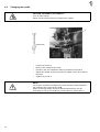
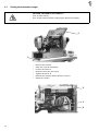
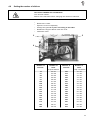
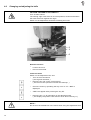
1
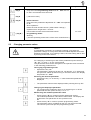
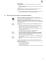
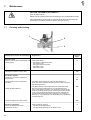
Home
Contents
Page:
Preface and General Safety Standards
Part 1: Operating Instructions cl. 577-1111
1.
Product description . . . . . . . . . . . . . . . . . . . . . . . . . . . . . . . . . . . . . . . . . . . 5
2.
Normal use
3.
Technical data
4.
4.1
4.2
4.3
4.4
4.5
4.6
4.7
4.8
4.9
4.10
Operation
Threading the needle . . . . . . . . .
Winding the hook thread . . . . . . .
Inserting the bobbin . . . . . . . . . .
Changing the needle . . . . . . . . .
Lifting the sewing cage . . . . . . . .
Regulating the sewing cage pressure
Setting the buttonhole length . . . . .
Setting the number of stitches . . . .
Changing and adjusting the knife . .
Thread tension . . . . . . . . . . . . .
5.
5.1
5.2
5.3
Control and control panel
General . . . . . . . . . . . . . . . . . . . . . . . . . . . . . . . . . . . . . . . . . . . . . . . . . . . 17
Keys on the control panel . . . . . . . . . . . . . . . . . . . . . . . . . . . . . . . . . . . . . . . . . 18
Changing parameter values . . . . . . . . . . . . . . . . . . . . . . . . . . . . . . . . . . . . . . . 19
6.
6.1
6.2
6.3
Sewing
Normal sewing cycle . . . . . . . . . . . . . . . . . . . . . . . . . . . . . . . . . . . . . . . . . . . 22
Interruption of th4e sewing cycle . . . . . . . . . . . . . . . . . . . . . . . . . . . . . . . . . . . . . 22
Monitoring the hook thread by counting the buttonholes . . . . . . . . . . . . . . . . . . . . . . . . 23
7.
7.1
7.2
Maintenance
Cleaning and checking . . . . . . . . . . . . . . . . . . . . . . . . . . . . . . . . . . . . . . . . . . 24
Lubrication . . . . . . . . . . . . . . . . . . . . . . . . . . . . . . . . . . . . . . . . . . . . . . . . . 25
8.
Auxiliary equipment . . . . . . . . . . . . . . . . . . . . . . . . . . . . . . . . . . . . . . . . . . . 26
. . . . . . . . . . . . . . . . . . . . . . . . . . . . . . . . . . . . . . . . . . . . . . . . 5
. . . . . . . . . . . . . . . . . . . . . . . . . . . . . . . . . . . . . . . . . . . . . . 6
.
.
.
.
.
.
.
.
.
.
.
.
.
.
.
.
.
.
.
.
.
.
.
.
.
.
.
.
.
.
.
.
.
.
.
.
.
.
.
.
.
.
.
.
.
.
.
.
.
.
.
.
.
.
.
.
.
.
.
.
.
.
.
.
.
.
.
.
.
.
.
.
.
.
.
.
.
.
.
.
.
.
.
.
.
.
.
.
.
.
.
.
.
.
.
.
.
.
.
.
.
.
.
.
.
.
.
.
.
.
.
.
.
.
.
.
.
.
.
.
.
.
.
.
.
.
.
.
.
.
.
.
.
.
.
.
.
.
.
.
.
.
.
.
.
.
.
.
.
.
.
.
.
.
.
.
.
.
.
.
.
.
.
.
.
.
.
.
.
.
.
.
.
.
.
.
.
.
.
.
.
.
.
.
.
.
.
.
.
.
.
.
.
.
.
.
.
.
.
.
.
.
.
.
.
.
.
.
.
.
.
.
.
.
.
.
.
.
.
.
.
.
.
.
.
.
.
.
.
.
.
.
.
.
.
.
.
.
.
.
.
.
.
.
.
.
.
.
.
.
.
.
.
.
.
.
.
.
.
.
.
.
.
.
.
.
.
.
.
.
.
.
.
.
.
.
.
.
.
.
.
.
.
.
.
.
.
.
.
.
.
.
.
.
.
.
.
.
.
.
.
.
.
.
.
.
.
.
.
.
.
.
.
.
.
.
.
.
.
.
.
.
.
.
.
.
.
.
.
.
. 7
. 8
. 8
. 10
. 11
. 11
. 12
. 13
. 14
. 16
3
Stand set for longitudinal installation
Stand set for transversal installation
Stand set for transversal/longitudinal operation
4
1.
Product description
The DÜRKOPP ADLER 577-1111 is an automatic double lockstitch
machine with bottom and top feed for sewing buttonholes with two
straight bars.
Normal sewing mode:
During the sewing process the fabric face ( the face seen) ) is up.
The machine can be supplied in three installation variants ( see on the
left ).
2.
Normal use
The automatic sewing machine DÜRKOPP ADLER 577-1111 has been
designed for sewing light to middle-heavy weight material, as used in
the apparel industry.
Such material consists generally of textile or synthetic fibres.
Furthermore, the machine lends itself for producing so-called technical
seams. In this case, the user must estimate any possible dangers
(contact dürkopp adler ag for help), Technical seams are seldom, but
they may be very versatile. Proper safety precautions, depending on
the result of such an estimation, must be taken. Generally, only dry
material should be sewn on this machine. And the material should not
exceeded the thickness of
4 mm when compressed by the lowered sewing foot.
The material should not contain any hard objects, because otherwise it
would be necessary to protect the eyes during the sewing process..
For the time being, no such eye guard is available. The seams are
produced generally with threads up to 65/2 Nm ( cotton-covered
synthetic threads or synthetic threads ) Before using any other threads
it is necessary, also in this case, to estimate the consequential
dangers and to take, if necessary, the respective safety measures.
This automatic sewing unit should be installed and operated only in
dry and proper rooms. Otherwise, further precautions (to convene)
may be needed, ( siehe EN 60204-3-1:1990 ). We.manufacturers of
industrial sewing machines, assume, that our machines will be
operated at least by a well trained staff, knowing all usual controls and
any possible dangers.
5
3.
Technical data
Machine heads:
Class 577-1111
Needle system:
Needle thickness:
Threads:
System 265, needle point slightly rounded off
70 - 100, Standard 80
Synthetic threads, and cotton-coated
synthetic threads
Stitch type:
Speed:
Up to 65/2 Nm
Double lockstitch
up to. 4000 rpm ( adjustable )
Number of stitches
Per seam pattern:
76 - 510
Buttonhole length:
Buttonhole width:
10 - 48 mm
0 - 6 mm
Cut length:
max. 38 mm
Motor type:
Nominal performance:
Speed:
EFKA DC1600/DA82GL
0,75 kW
4000 U/min
Service pressure:
6 bar
Air consumption:
about 4 NL per working cycle
Nominal voltage:
1 ~ 230 V, 50/60 Hz
1~ 190 - 240 V, 50/60 Hz
Dimensions:
Longitudinal stand:
1060 x 620 x 1250 mm ( L x B x H )
Longitudinal/transversal
stand:
800 x 650 x 1250 mm ( L x B x H )
(Machine head without stand: 180 x 600 x 450)
6
Working level:
Weight:
750...895 mm ( Table top )
ca. 135 kg ( with stand )
Rated noise level:
Lc = .... dB (A)
4.
Operation
4.1
Threading the needle
CAUTION: DANGER OF ACCIDENTS !
Turn off main switch!
Switch off the machine before threading the needle.
–
Thread then needle according to the illustration.
7
4.2
Winding the hook thread
3
1
2
–
–
–
–
–
–
–
–
4.3
Slip the reel onto its stand.
Thread the hook according to the illustration.
Slip the bobbin onto the bobbin winder 1 .
Wind the hook thread clockwise about 5 times around the bobbin
core.
Swing bobbin winder lever 2 towards the bobbin and let it snap.
The thread will be wound during the sewing process.
The bobbin winder lever 2 will stop the winding process as soon as
the bobbin is full.
Following the winding process, tear off the bobbin thread at the
thread clamp 3.
Inserting the bobbin
CAUTION: DANGER OF ACCIDENTS !
Turn off main switch!
Switch off the machine before changing the bobbin!
Removing empty bobbin.
– Open hook space cover 4.
– Lift the bow 5 and remove bobbin case top together with the
bobbin.
– Remove the empty bobbin from the bobbin case top.
8
5
4
Threading the bobbin
– Insert the full bobbin into the bobbin case top. When unwinding the
thread, the bobbin must turn clockwise.
– Pass the hook thread through the slit 6 and under the spring 7.
– Depending on the buttonhole to be sewn, pass the hook thread
through the slit 9 for a raised buttonhole ( more thread will be
advanced across the hook back) ) or through the slit 10 for a flat
buttonhole ( less thread ).
– Cut then the thread, passed as described, by the knife 11.
Adjusting the hook thread tension
– Adjust the hook thread tension by turning the screw 12 so that,
when holding the thread at its end, the bobbin case descends by
its own weight.
11
6
9
10
12
7
Inserting the bobbin case top
– Place the bobbin case top together with the bobbin onto the bobbin
case bottom and ensure that the bow 5 snaps (what you should
hear).
– Close the bobbin space cover 4.
9
4.4
Changing the needle
CAUTION: DANGER OF ACCIDENTS !
Turn off main switch!
Switch off the machine before changing the needle!
1
Knife side
–
–
–
–
–
Loosen the screw 1.
Remove the neelde from its bar.
Introduce the new needle as deep as possible into its bar a.
Adjust the needle so that its furrow is located on the other side of
the knife.
Tighten the screw 1.
NOTE !
The factory-set distance between the hook and the needle applies to
the needles having a thickness of 80.
When inserting a needle having a different thickness it may be
necessary to correct the distance ( see the Service Instructions ).
10
4.5
Lifting the sewing cage
The sewing cage 2 will be lifted only if the main switch is turned on
and if following conditions exist:
– Sewing cage in initial position ( rear p. )
– Thread take-up lever in top dead-center position ( needle in upper
position )
If the thread take-up lever does not stand in its top dead-center
position ( error message in the display of the control panel: "_0 1 0" ),
the machine will automatically turn into this position after turning on
the main switch.
After turning on the main switch, following message will be presented
on the display of the control panel: "_0 1". if the sewing cage does
not stand in its initial position Turn then the crank until the sewing
cage stands in the proper position and can be lifted. By treading the
pedal forwards into its 1 st position, the sewing cage will be lowered
without starting the sewing process.
The sewing cage can be lifted and lowered by the key 3 on the control
panel. Then it is necessary to switch on the parameter "F - 020" on
the operator level ( see chapter 4.9 ).
3
2
4.6
Regulating the sewing cage pressure
–
The sewing cage pressure can be regulated by the screw 3.
11
4.7
Setting the buttonhole length
CAUTION: DANGER OF ACCIDENTS !
Turn off main switch!
Turn off the machine before changing the buttonhole length!
2
1
–
–
–
–
–
–
–
Remove the crank 1.
Open the cover 2 completely.
Loosen the screw 3.
Reset the lever 4 in the crank.
Tighten the screw 3.
Release the support 5 and close the cover 2.
Install the crank 1.
5
3
4
12
4.8
Setting the number of stitches
CAUTION: DANGER OF ACCIDENTS !
Turn off main switch!
Switch of the machine before changing the number of stitches!
–
–
–
–
–
Remove the crank.
Open the cover 2.completely
Change the gears 6 in pairs according to the table.
Release the support 5 and close the cover.
Install the crank.
5
2
6
Number of
stitches
76
81
86
91
97
102
108
114
120
127
134
141
149
157
165
173
182
192
Number of
teeth
at top/at bottom
22 / 57
23 / 56
24 / 55
25 / 54
26 / 53
27 / 52
28 / 51
29 / 50
30 / 49
31 / 48
32 / 47
33 / 46
34 / 45
35 / 44
36 / 43
37 / 42
38 / 41
39 / 40
Number of
stitches
202
212
223
235
247
261
274
289
305
321
339
358
379
401
425
451
479
510
Number of
teeth
at top / at bottom
40 / 39
41 / 38
42 / 37
43 / 36
44 / 35
45 / 34
46 / 33
47 / 32
48 / 31
49 / 30
50 / 29
51 / 28
52 / 27
53 / 26
54 / 25
55 / 24
56 / 23
57 / 22
13
4.9
Changing and adjusting the knife
CAUTION: DANGER OF ACCIDENTS !
Turn off main switch!
The sewing cage must stand in its initial position, because otherwise
the knife will knock against the cage!
Switch on the adjustment aid before installing the knife!
3
1
2
Remove the knife
– Loosen the nut 1.
– Pull out the knife 2.
Install the knife
Switch on the adjustment aid, and:
– Turn on the main switch.
( the cage will be lifted. )
– Press the key "P" on the control panel.
( The menu of the operator level will be called up. )
–
Cross the menu by operating the key until "+" "F - 020" is
displayed.
–
"oFF" will appear after pressing the key "E".
–
Press the key "+" for switching on the adjustment aid.
( The display will present "on" and an arrow above the key 3. )
NOTE !
Do not turn the handwheel or the crank when using the adjustment aid!
14
–
Insert new knife ( loosen nut 1 ) and push it first up to the top.
NOTE !
It is absolutely necessary to note that the distance between the upper
thread scissors and the knife bottom amounts to at least. 1 mm.
–
–
Tighten the nut 1.
Lower the sewing cage by pressing the key Taste 3.
–
With the adjustment aid still being engaged, it is now possible to
lower the knife block by operating the key 4.
( An arrow will appear above the key 4. )
–
Operate the key 4 once again for lifting the knife block.
The knife block cannot be moved down by the key 4 as long as the
sewing cage is not lowered. Therefore, first lower the sewing cage by
the key 3. Also the function of the key 3 (lifting the sewing cage) is
locked as long as the knife is in its lower position.
It will be impossible to start the machine as long as the adjustment aid
is engaged.
Adjusting the knife
When the knife block is lowered, the front edge of the knife should
stand about. 2 mm under the bottom of the throat plate.
Adjustment:
– Lift the sewing cage.
– Loosen slightly the nut 1.
– Displace the knife.
– Tighten the nut 1.
– Check the cutting depth and repeat the process, if required.
The cut of the knife should be about 2 tissue threads from the last
sewn final bartack.
Adjustment:
– Loosen the screw 3 and adjust the distance accordingly.
Note:
When the knife block is in its lowered position, the safety distance
between the front edge of the knife and the slit in the throat plate
insert must amount to 0,5 mm.
– Tighten the screw 3.
End the adjustment aid
For ending the adjustment aid press the key "P" on the control panel.
15
4.10
Thread tension
The machine head has been set in the factory for sewing buttonholes
with flat bartacks and with raised lips.
4
5
6
Pre-tension
The pre-tension 4 is always active. It serves for stabilising the needle
thread. It should be set to the minimum value ( 5-10 g ). The
pre-tension 4 has scarcely any influence on the seam pattern.
Main tension
The main tension 5 is active when sewing both buttonhole lips. But the
main tension 5 it is out of action when bartacking and when cutting the
threads.
Bartack tension
The bartack tension 6 is opened only when cutting the threads. It is
remains closed during the entire remaining sewing process.
Buttonhole lip tension
The buttonhole lip tension is produced jointly by the main tension 5
and by the bartacking tension 6. About 1/3 of the buttonhole lip tension
should be produced by the bartacking tension 6.
Adjustment
– Thread the needle thread so that it does not pass through the main
tension 5.
– Start the sewing process.
16
–
Adjust the bartacking tension 6 so that the maximum possible
quantity of the thread unwound is consumed during the sewing
process. But ensure that the thread does not flatter above the
pre-tension and that it is not torn.
– Thread the needle according to the chapter 4.1.
– Start the sewing process according to the chapter 6.
– Adjust the main tension 5 so that a satisfactory seam pattern is
obtained when sewing the buttonhole lips ( regularly raised lips ).
If the seam quality is worse after a thread change, proceed to a
correction. Turn only the main tension 5.
Control
– Use threads of different colours for threading the needle and the
hook.
– Carry out a sewing test.
When using two-colour threads, the colour of the needle thread in the
bartacks should be visible only from above.
5.
Control unit and control panel
The present Manual describes only the function of the keys and the
change of parameters by the operator.
For a detailed description of the control unit see the attached actual
Operating Instructions of the motor manufacturer.
5.1
General
The control panel is used for programming the control unit and for
setting the respective seam functions.
This is done partly directly by operating the respective keys or by
changing the parameters.
The parameters are entered in the programming mode. The
parameters and the assigned values are presented by the display..
In order to avoid any involuntary chages of the pre-set parameters, the
attendance of the control panel is subdivided into different levels (
operator, technician, fitter ).
The operator has a direct access to its level.
For having an access to the other levels it is necessary to enter a code
number or it is necessary to press several keys simultaneously.
NOTE !
Do not turn the handwheel or the crank during the parameter change
on the operator level!
Reset
When the control unit is totally out of adjustment, the technician can,
by means of a Reset Function, reset all adjustment values to the state
existing at the moment of delivery.
The Reset Function is described in the Service Instructions.
17
1
5.2
3
4
A
B
Keys on the control panel
Function
Key
18
2
Adjustments
P
Call up/end programming mode
E
( Only in the programming mode )
Displaying the parameter value / Rendering the parameter value for a change
Quitting a parameter entry with a simultaneous change to
the next parameter
+
Direct function:
Increase the speed
In programming mode:
Change to the next parameter of the parameter list
Increase the displayed parameter value / Switch on the
displayed parameter ( "on" )
-
Direct function:
Reduce the speed
In the programming mode:
Return to the previous parameter of the parameter list
Reduce the displayed parameter value / Switch off the
displayed parameter ( "oFF" )
Key 1
Soft start
on / oFF
Key 2
Double cycle
on / oFF
Key 3
Only when the Programming mode and "F - 020" are
set to "on" lifting/lowering the sewing cage
Key 4
Only when the Programming mode and "F - 020" are set
to "on" connect/disconect the knife
Key A
( without function )
Key B
Direct function:
Only when the parameter adjustment "F - 195" corresponds
to "4"
Short operation:
Reset the hook thread counter ( after bobbin change )
Operation time longer than 1 second:
Connect/disconnect the hook thread counter
Programming mode:
Shift key
( see the Operating Instructions of the motor manufacturer )
( Key B )
5.3
Adjustments
Function
Key
on / oFF
Changing parameter values
NOTE !
It is absolutely necessary to complete a sewing cycle after the
parameter change. It is only then that the modified adjustment will be
definitely memorised. If no sewing is done, the new setting will be lost
by turning off the main switch!
For changing or switching on and off the parameters press the keys
"P", "E", "+" and "-" on the control panel.
The parameters that can be changed on the operator level are stated
in the following parameter list.
Calling up programming mode
– Operate the key "P".
The parameter, called up as last one, will appear.. If no parameter
has yet been called up after turning on the main switch, the display
will present "F - 000".
Selecting the desired parameter
– Operate the key "+" or the key "-".until the desired parameter is
displayed
–
The parameter value will be displayed after pressing the key "E".
Changing the displayed parameter
– For changing the parameter value or for switching on or off the
parameter function press the keys "+" or "-".
Memorising the modified parameter value
– Press the key "E" for changing further parameter values.
The modified parameter value will be memorised. The display will
present the next parameter on the operator level.
or:
– Press the key "P" in order to quit the programming mode.
The parameter value, modified as last one, will be memorised.
The control system will quit the programming mode.
19
Parameter list on the operator level
Parameter
Denomination
max
Adjustment
min Standard
F - 000
Buttonhole counting On/Off
(This function is only possible
when the machine speed display,
Parameter "F - 139", is switched
off )
on
oFF
oFF
F - 001
Reset buttonhole counting
on
oFF
oFF
F - 020
Adjustment aid for the knife and for
the thread cutter, connected mechanically with the sewing cage.
The following functions are enabled only when the needle stands
in its upper position and the sewing cage in its rear position .
on
oFF
oFF
Key "+"
on
Key 3
right arrow On
Sewing cage in upper
position
Key 3
right arrow Off
Sewing cage in lower
position
Key 4
right arrow On
Knife On
Key 4
right arrow Off
Knife Off
Only one function at a time can be
controlled!
20
F - 080
Correction ( + ) of the after-running
stitches at the buttonhole end
10
0
0
F - 081
Correction ( - ) of the after-running
stitches at the buttonhole end
10
0
0
F - 085
Number of buttonholes for the
hook thread monitor
"F - 195" to "1...4"
3000
0
0
State Display
Display
Denomination
InF P1
Error in the determination of the after-running stitches.
The number of the after-running stitches is too low.
InF P2
Error in the determination of the after-running stitches.
The number of the after-running stitches is too high.
The machine runs
The hook thread monitor can be switched on.
( only when the parameter "F - 195" is set to "4" )
blinking symbol:
The counting for the hook thread monitor has commenced.
Blinking symbol and display of "C D":
The counting has ended, change the bobbin!
The display of the control panel will present up to 4 different
inadmissible conditions resulting from a number combination.
A
_1 1 1 1
Sewing cage not in its initial position (rear pos)
Thread take-up lever not in its top dead centre
position. (needle not in upper pos.)
Needle thread monitor acting
Instant stop has been released ( stop )
A combination of several inadmissible conditions is possible, e.g.:
A
_0101
Needle thread monitor active / Sewing cage not in rear
position
Display of the sewn buttonholes.:
B
12345
max. 65535
The counting for the hook thread monitor has ended.:
CD
12345
21
6.
Sewing
NOTE !
Do not start sewing with the machine before is has been fully
assembled and before, among others, all the protective devices has
been installed.!
6.1
Normal sewing process
Start the sewing process
– Turn on the main switch.
– If the sewing cage is not lifted, turn the crank until the sewing cage
stands in its rear position ( initial position ). The sewing cage will
be lifted.
– Insert the material to be sewn.
– Start the sewing process by treading the pedal forwards
( the sewing cage will be lowered, the buttonhole will be sewn, the
knife will act, the threads will be cut off and the sewing cage will be
lifted )
– For being able to start a new sewing process, Before the end of
the sewing process, the pedal must be returned to its neutral
position, in order to enable the start of the next sewing cycle.
6.2
Interruption of the sewing cycle
The sewing cycle can be interrupted as follows:
Interruption by the operator
– By treading the pedal backwards, the sewing process will be
interrupted within the buttonhole.
– The error message "_1 0 " will be displayed.
– Turn off main switch and eliminate the cause for the interruption.
Interruption by thread breakage
– The error message "_0 1 0 " will be displayed.
– The sewing cage will be moved, without needle thread, up to the
buttonhole end, the knife and the thread cutter will not act and the
sewing cage will not be lifted.
– Thread the needle according to chapter 4.1.
Following is to be noted after an interruption
– If the sewing cage stands in its initial position ( rear position ), it
can be lifted by treading the pedal backwards.
– If the commenced buttonhole is to be completed by a repair seam,
the sewing cage should not stand in its initial position (rear
position) when the main switch is turned on again, because
otherwise it will be lifted.
Before turning on the main switch, take the sewing cage to the
repair point by turning the crank.
– If the repair point lies within the second half of the second
buttonhole lip (short before the buttonhole end), a complete
buttonhole will be sewn as a repair seam.
22
Go on sewing
After an interruption, there are three possibilities to continue the
sewing process:
– Continue the sewing process out of the actual position by treading
the pedal forwards
or
BLICKFANG-STR = Take the sewing cage to the desired point by
turning the crank and restart the sewing process here
or
– take the sewing cage to its initial position (rear position)by turning
the crank and lift the cage for removing the material.
6.3
Monitoring the hook thread by counting the buttonholes
When the parameter "F - 195" has been set to the value "4" (
technician level, see the Service Instructions ), the bobbin symbol will
appear on the right side of the display
The operator can, by maintaining this position and by using the
parameter "F - 085" enter the number of buttonholes ( 1 - 3000 ) that,
according to the experience, can be sewn with one hook thread bobbin
( see chapter 5.3 ).
For starting the buttonhole counting, press the key B, longer than 1
second:
– The bobbin symbol will be blinking during the sewing process.
– After the number of buttonholes, entered under the parameter "F 085" the sewing cage will not be lifted automatically.
– In addition to the blinking bobbin symbol, the display will present
the blinking letters "C D".
– Lift the sewing cage by treading the pedal backwards.
– Change the bobbin according to the chapter 4.3.
– Reset the buttonhole counting by a brief operation of the key B.
The letters "C D" will disappear, the buttonhole counting will
remain switched on ( the bobbin symbol will be blinking ) and the
buttonhole counting will be re-started.
– For switching off the buttonhole counting, press the key B longer
than 1 second.
( the bobbin symbol will still be displayed and it will no longer be
blinking. )
After having completed the pre-set number of buttonholes, further
buttonholes can possibly be sewn if the rest of the hook thread on the
bobbin is still sufficient:
– Lower the pedal backwards.
The sewing cage will be lifted.
– Lower the pedal forwards.
The buttonhole will be sewn, but the sewing cage will not be lifted.
23
7.
Maintenance
CAUTION: DANGER OF ACCIDENTS !
Turn off main switch
Switch off the machine before proceeding to any maintenance work!
The maintenance work must be carried out at least at the intervals
specified in the table ( see the column Service hours ).
7.1
Cleaning and checking
1
2
3
Maintenance work to be carried out
Machine head
Remove sewing dust, thread ends and
cutting waste.
Explanation
Clean particularly:
- the bottom of the throat plate
- the sewing cage
- the space around the hook
- the bobbin case
- the thread cutter
Sewing motor
Check the condition of the V-belt.
Service
hours
8
160
Pneumatic System
Check and, if required, adjust the
air pressure.
8
40
Check water level in the pressure
regulator.
Clean the filter element.
The water level should not reach the filter element 1.
Drain the water separator 2 under pressure after turning-in
the draining screw 3.
The filter element 1 separates dirt and condensed water.
Disconnect the machine from the compressed air line.
Turn-in the draining screw 3. The pneumatic system of the
machine must be pressure-free. Unscrew the water separator 2. Unscrew the filter element 1 and wash the filter tray
and the filter element petroleum benzine ( no solvents! )
Bow dry by compressed air. Re-assemble and re-install the
conditioning unit.
Check the tightness of the system.
Auxiliary equipment
Clean the light barrier of the –
thread rest monitor.
24
500
500
Clean following element:
- The lens of the light barrier
- The light beam passage in the bobbin case
8
7.2
Lubrication
CAUTION: DANGER OF ACCIDENTS !
Oil can irritate the skin!
Avoid long contacts with the skin!
Wash the contaminated skin thoroughly!
NOTE !
The handling and the disposal of mineral oils is subject to legal
regulations.
Deliver waste oil exclusively to an authorized reception center!
Protect your environment, do not spill any oil!
For filling the oil supply containers, used exclusively the lubrication oil
ESSO SP-NK 10 or an equivalent oil with the following specification:
– Viscosity at 40°C:
10 mm 2 /s
– Point of inflammation:
150°C
The oil can be obtained from the sales centres of
DÜRKOPP ADLER AG under the following reference numbers:
– 2-Litre container:
9047 000013
– 5-Litre container:
9047 000014
2
1
Maintenance work to be carried
out
Explanation
Hook lubrication
Check oil level in the supply
container 1.
Tilt the machine head backwards.
Fill the oil supply container 1 through the respective hole up to
the mark "max".
8
Lubrication of the machine head
Check oil level in the supply
container 2.
The oil level should not drop below the mark "min".
If required, fill the oil through the hole in the sight glass up to
the mark "max".
40
Service
hours
25
8.
Auxiliary equipment
Auxiliary equipment
Reference No..
Designation
0577 211324
Vulkollan-coated cloth presser cage
and smooth fabric feeder for E 113/22
0577 211424
Vulkollan-coated cloth presser cage
and smooth fabric feeder for E 114/22
0577 211444
Vulkollan-coated cloth presser cage
and smooth fabric feeder for E 114/35
9822 510000
Stand-type halogen sewing light
9822 510011
Table clamp for stand-type halogen sewing
light
0797 003031
Pneumatic connection package
Loading aids
26
Reference No..
Designation
0556 002741
Buttonhole spacer and
Edge guide for sewing in longitudinal direction
0556 002656
Collar guide
0556 002654
Cuff guide
0556 002652
Buttonhole spacer;
for transversal sewing, max. 360 mm
0556 002651
Buttonhole spacer;
for transversal sewing, max. 160 mm
0556 002581
Edge guide for longitudinal sewing