1
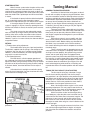
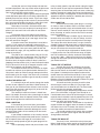
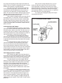
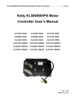
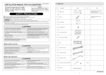
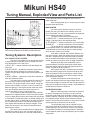
Mikuni HS40
Tuning Manual, Exploded View and Parts List
jet. It is generally easier to change the air jet since it is
more accessible.
After changing either jet, it is necessary to re-adjust
the pilot screw for best idle.
Figure 1: Diagram showing the effective range of the
each tuning component of the Mikuni HS40 carburetor
Tuning Systems: Description
IDLE CIRCUIT (PILOT SYSTEM)
The idle circuit supplies fuel at idle speeds and has
a major influence on fuel flow up to 1/4 throttle. There are
three tunable parts in the idle circuit:
1) PILOT JET --- controls maximum fuel flow through the
idle circuit.
2) PILOT AIR JET--- controls the maximum amount of fuel
that will flow through the pilot jet by allowing a higher
(smaller air jet) or lower (large air jet) vacuum signal at the
pilot jet.
3) PILOT SCREW --- controls how much fuel is allowed to
enter the carburetor venturi.
The pilot screw is used to control idle mixture. Turn
the screw out to richen the idle mixture. Turn it in to lean
the mixture. The engine should have a smooth, steady idle
with the screw between 1/4 and 3-1/2 turns out from fully
bottomed (gently!). If the engine requires more than three
turns out, the pilot or pilot air jet may be too lean. If it
requires less thatn 1/4 turn, it may be too rich.
As the throttle is opened the pilot screw’s position
becomes less important than the sizes of the pilot and pilot
air jets. A larger pilot jet richens the mixture from just off-idle
to 1/4 throttle. A smaller one leans it. A change in pilot air jet
has the reverse effect. A larger pilot air jet leans the mixture
and a smaller one richens it. The pilot jet and pilot air jet
have slightly different effects on mixture strengths. These
effects are discussed in the “General Tuning Procedure”
portion of this manual.
The idle circuit can be adjusted by changing either
the pilot or the pilot air jet. A one-size larger pilot jet will
have nearly the same effect as a one-size smaller pilot air
MAIN SYSTEM
The main system dielivers fuel from 1/16 to full
throttle. The idle circuit delivers the mahority of the fuel
near 1/16 throttle. The main system becomes the important
mixture control from about 1/4 throttle.
The main system has three tunable parts:
1) NEEDLE JET --- controls mixture from 1/16 to approximately 1/4 throttle (varies with needle position).
2) JET NEEDLE --- controls mixture from 1/4 to 3/4 throttle.
3) MAIN JET
--- controls mixture from 3/4 to full throtle
The jet needle has a constant diameter section
and a tapered section. The diameter of the needle and the
inside diameter of the needle jet form an orifice through
which all main system fuel must flow.
Until about 1/4 throttle, the constant diameter section of the needle is within the needle jet and main system
fuel flow is controlled by the size of the needle jet. Needle
jets are available with different inside diameters. A larger
needle jet richens the mixture within its range of operation.
Notches at the top of the needle allow it to be
raised or lowered. Raising or lowering the needle determines the throttle setting at which the tapered part of the
needle is raised out of the needle jet.
Main system fuel flow is controlled by the needle’s
taper from where it begins to lift out of the needle jet until
about 3/4 throttle. Raising or lowering the needle respectively richens or leans the mixture from that point until the
main jet becomes effective.
At about 3/4 throttle the orifice formed by the
needle and needle jet becomes large enough that the size
of the main jet begins to control fuel flow. Until this point the
main jet has no effect on mixture strength. At full throttle the
needle taper has little or no influence.
ACCELERATOR PUMP
Mikuni’s HS40 carburetor is fitted with an accelerator pump. The purpose of the pump is to inject fuel into
the throat of the HS40 when the throttle is opened. As the
throttle is opened, especially at low rpm, air velocity through
the carburetor drops and the mixture naturally becomes
leaner. Fuel from the pump maintains a more correct fuel/air
mixture until the air velocity returns to normal.
The accelerator pump can be adjusted to inject
fuel into the throat of the carburetor over a wide range of
throttle openings. The rate at which it injects fuel can also
be controlled with different sized pump nozzles. Total flow
volume depends upon the pump’s beginning and end point
adjustments.
STARTER SYSTEM
Mikuni’s starter system takes the place of the crude
choke mechanism of the stock carburetor. It is actually a
small auxilliary carburetor designed to supply a rather rich
mixture for starting purposes. The starter system only works
when the choke knob is pulled open and when the throttle
is closed.
If the throttle is opened with the choke knob pulled
out, air essentially ceases to flow through the starter
system and it stops delivering its rich mixture to the engine.
If the engine begins to load-up while the starter
system is engaged, it may be cleared by opening the throttle. When the throttle is closed, the starter system resumes
operation.
The starter system has one replaceable component, the starter jet. A larger starter jet makes the starter
mixture richer and a smaller one makes makes it leaner.
The #55 jet fitted to the HS40 will suit most installations.
However, if you live in a warm climate, the alternate #45 jet
may perform better.
DETAILS
1) Throttle return spring adjustment:
The throttle return spring has 3 pre-load positions.
The HS40 is supplied with the spring in the stronger of the
3 positions. You may wish to try a weaker spring position.
However, in some installations, the softer spring position
may result in erratic return to idle.
2) Fuel float adjustment:
Fuel float level is critical to proper operation of
any carburetor, the HS40 is no exception. Mikuni correctly
adjusts the floats during assembly but they may be accidentally bent out of adjustment during tuning or other handling.
If you have doubts, check the float level and re-adjust if
needed.
A float level that is too high can make fine tuning
of the idle circuit impossible. One that is too low will have a
similar effect on mid-range tuning.
Figure 2: Diagram showing float level range and checking
procedure.
Tuning Manual
GENERAL TUNING PROCEDURES
Your Mikuni is fitted with the tuning parts we found
to work with a majority of engine tuning combinations. However, the tremendous number of differing exhaust systems
and cams available for Harley engines make it impossible to
accommodate all possible combinations with one carburetor set-up. You will probably find that the HS40 will run
perfectly on your engine without exchanging any parts. But
if it doesn’t, you may alter its tuning to suit your engine’s
needs by following this guide.
There are many more replaceable parts that affect
tuning in the HS40 than in the stock Harley carburetor. With
these parts you can precisely tailor the HS40’s tuning to
your engine’s requirements throughout its rpm and throttle
setting range.
Each tuning system is easy to modify and diagnose, but only when you understand what each system
does and how it works. Before making any alterations to
the HS40, if any are needed at all, read the section of
this manual describing the various components and their
functional range.
There is simply no point in attempting to tune any
carburetor unless the engine is completely sound. Valves
and rings must seal properly, the ignition timing must be
correct and the spark plugs clean and gapped. Some
exhaust systems may also make carburetor tuning difficult.
For instance, it is almost impossible to get smooth responsive carburetion with straight and open pipes. If you have
and doubts about the condition of your engine, tune and
test it before beginning what could be a frustrating and
unproductive effort to fix another problem with the carburetor.
TUNING THE IDLE CIRCUIT (PILOT SYSTEM)
The first step in tuning any carburetor is to get
the idle circuit correctly adjusted. And, the first step in
this procedure is to adjust the pilot screw position for best
idle. Mikuni sets the pilot screw at three turns open during
assembly. This is the position we have found to be right
most of the time. If the screw position has been altered,
gently bottom it and re-open to three turns out.
Next, ride the bike until the engine is at its normal
operating temperature. This may require several miles at
highway speeds. If you have an oil temperature gauge, ride
until the oil temperature is at or near 150 degrees.
With the machine vertical and the engine idling
near 1,000 rpm, adjust the pilot screw in one-half turn at
a time until the idle either slows or becomes irregular. The
pilot screw is now in too far and the idle mixture is too
lean. Pause for a few seconds at each half turn to allow
the engine to settle down and give a clear indication of the
mixture strength.
Now, begin turning the screw out in half turn intervals until the engine again slows or begins an irregular
idle. Count the turns between the too-lean and too-rich
positions.
Set the pilot screw mid-way between the too-lean
and too-rich positions. You may further refine the pilot screw
position with riding experience but this setting will be very
close to the correct idle mixture setting.
If you allow the engine to get too hot during the pilot
screw adjustment procedure, the resulting adjustment will
probably be on the lean side of correct. If you have a large
fan use it while adjusting the idle mixture. If you do not have
one, you may need to take time out for a short ride to cool
the engine back to the normal temperature range.
Remember, if best idle is achieved with the pilot
screw less that 1/4 turn out, the pilot jet is too large or the
pilot air jet is too small. One or the other will need to be
changed.
On the other hand, if the pilot jet screw must be
more than three and a half turns out for best idle, the pilot
jet is too small (or the pilot air jet is too large). One or the
other will need to be changed.
If the pilot screw’s best idle position is outside the
1/4 to 3-1/2 turn range, the carburetor’s mixture will be
either too lean or too rich as the throttle is just being raised
off the idle position. Once you have a good idle with the
screw within this range, you may proceed to the next stage:
tuning the needle jet.
The pilot air jet is selected while riding at 15 to 30
mph. If the engine surges or detonates (lean), the pilot air
jet should be reduced in size. Example: 1.1 to 1.0. If, on
the other hand, the engine misfires or there is after burn
(popping) from the exhaust (rich), it would indicate that pilot
air jet is too small. If the air jet is changed, the pilot screw
should be re-checked and adjusted if needed.
As mentioned earlier, the idle circuit has an important effect on mixtures up to quarter throttle. However, the
idle system’s effect on mixture strength overlaps the effect
of the neelde jet in this range. If the idle circuit is incorrectly
adjusted, it will not be possible to get the needle jet correct.
TUNING THE NEEDLE JET
It is unlikely that you will need to change the needle
jet from the one supplied in your Mikuni HS40. However, in
case you do, you should be aware of how it works and how
to tell if the one you have it too large (rich) or too small for
your particular engine set up.
The needle jet’s effect on mixture is limited from
about 1/16 throttle, where the main system begins to deliver
fuel, to 1/4 throtlle, when the tapered section of the needle
begins to emerge from the mouth of the needle jet.
LEAN CONDITION
If the needle jet is too small (lean), part throttle
acceleration will be flat. There may also be some detonation during part throttle acceleration although this can be
caused by other factors. A lean needle jet will also result
in a slow warm up.
If part throttle acceleration is flat, install a one-size
larger needle jet and compare the performance. If acceleration is improved, leave the larger jet in and take a fairly
long ride at steady speeds to give the spark plugs time to
color evenly.
Take a spark plug wrench with you and after a few
miles at steady speeds, stop and remove a plug for inspection. Be careful as you stop not to operate the throttle. The
extra fuel from the accelerator pump can cause a false plug
reading. The body of a spark plug can be from light grey to
brown to dark grey. If the plug body is black and has a sooty
appearance then the needle jet is probably too rich and a
smaller one will need to be fitted.
RICH CONDITION
While a black and sooty spark plug is a sure sign
of richness, there are others that are a bit more subtle. If
your engine responds crisply at low throttle when it is cold,
chances are the needle jet is one size larger than it needs
to be. Assuming, of course, that the idle circuit is correctly
tuned and adjusted.
Poor fuel mileage is another sign of richness and
because of the way most of us ride our Harleys, that richness is usually the result of a needle jet that is too large.
The color of the end of the exhausts is a sign of mixture
strength. Dark grey with some black is normal for today’s
lead free gasolines. If the exhaust color is black, chances
are you can reduce the size of the needle jet.
It may be that you might prefer a needle jet that
is slightly on the rich side of the correct range. A slightly
over-rich condition lets a Harley accelerate a little better
at very low (1,000 - 1,500) rpm and with very low throttle
settings. Be aware that you will lose some fuel economy if
you choose to do this.
TUNING THE JET NEEDLE
Like the idle circuit and needle jet, the needle,
within its range of operation, has a gradually increasing
effect on fuel mixture as the throttle is opened. From the
time (about 1/4 throttle) that the tapered section of the
needle leaves the mouth of the needle jet, it has a major
effect on the on the amount of fuel entering the engine.
Between 1/2 and 3/4 throttle the needle’s influence is greatest and it contols most of the fuel flow.
All needle and main jet testing should be done
wiht the engine near the middle of its rpm range. Start
your acceleration tests at about 50 mph. The best needle
position will give the strongest acceleration.
With the engine at operating temperature, accelerate at 1/2 to 3/4 throttle, in top gear, from 50 mph or so.
If acceleration seems soft or flat and the engine is slow to
respond when the throttle is quickly opened from the 1/2 to
the 3/4 throttle position, the mixture is too lean. Raise the
needle one notch and repeat the test.
One the other hand, if acceleration is crisp but the
engine hesitates or staggers when the throttle is suddenly
shut down from 3/4 to 1/2 throttle, the mixture is too rich.
Lower the needle one notch and repeat the test.
The needle position will be correct when acceleration is crisp at mid rpm yet the engine does not load up
during throttle shut down.
TUNING THE MAIN JET
You could, in fact, remove the main jet from your
Mikuni HS40 and the engine would run fine until the throttle
was near the 3/4 mark. The needle and needle jet restrict
the amount of fuel getting into the engine until about that
position. There is no point in changing main jets if a mixture
problem exists below the 3/4 throttle position.
The main jet is the last jet you need to deal with
and is the easiest to get right, if you have the room. The
most effective method for getting the main jet right is to
measure the time required to accelerate between two
points. The start and end marker should be spaced so that
starting at about 35 mph at the first marker will have you
going past the second at near 55+ mph.
Select markers (telephone poles do nicely) that are
far enough apart, on a safe road, to meet the conditions
given above. As you pass the first marker, roll the throttle
fully open. Note the rpm or speed at the second marker.
The jet that gives the highest rpm or speed at the second
marker is the correct one. This method is simple and completely accurate.
ACCELERATOR PUMP TUNING
The beginning point of the stroke is adjusted with
adjusting screw #1 on the white plastic pump lever. To start
the pump sooner, back the screw out. Turn the screw in to
make the pump start its stroke at a larger throttle opening.
Most engines perform best if the pump begins its stroke as
soon as the throttle is moved from the idle position.
The end point of the accelerator pump stroke is
adjusted by the adjusting screw #2 located on the top of
the carburetor just behind the pump lever. Best performance
is generally achieved when the pump stroke ends at about
3/4 throttle.
It is important that the nozzle’s direction be correctly set. The nozzle is held in position by the friction
of its O-ring seal and can be turned quite easily with a
pair of long nosed pliers. Rotate the nozzle until the fuel
stream strikes the needle. This ensures an even distribution
of fuel between the front and rear cylinders. Nozzle adjustment should be made with the engine stopped and with a
minimum of pump strokes to avoid flooding.
FINE TUNING THE PILOT SYSTEM
NOTE: Before you apply any of the information in
this section be sure that the basic pilot system is correct. Be
sure that your engine idles smoothly with the mixture screw
between one and three turns out from its seated position.
The pilot and pilot air jets have slightly different
effects on mixture strength within the effective tuning range
of the pilot system (0/0 to 1/4 throttle). When you change
the pilot jet, it has a slightly greater effect on mixture
strength at zero throttle than it does at 1/4 throttle. On the
other hand, when you change the pilot air jet, it has a
slightly greater effect above 1/8 throttle that is does below
that setting.
If your engine has slightly soft acceleration just as
the throttle is raised from the idle position, the size balance
between the pilot jet and and pilot air jet may be incorrect.
If the softness is more pronounced whe the engine is at
normal running temperature, install a larger (leaner) pilot
air jet. If there is minor coughing or “popping” through the
carburetor when the engine is cool, install a smaller (richer)
pilot air jet.
After you have changed the pilot air jet, you will
need to re-adjust the mixture screw. If the new mixture
screw adjustment is outside the one to three turn range,
change the pilot jet. If the mixture screw must be more than
three turns out to get a correct idle, install the next larger
(richer) pilot jet. However, if less than one turn is required to
get a good idle fit the next smaller pilot jet.
It is unlikely that changing the pilot jet will require
changing the pilot air jet.
Figure 3: Accelerator pump stroke adjustor components