1
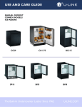
®
INSTALL GUIDE
2000 SERIES DRAWER MODELS
REFRIGERATORS
COMBO® REFRIGERATOR/FREEZER/ICE MAKERS
WINE CAPTAIN® MODELS
2275DWRCS
C2275DWROL
2275DWRCOL
C2275DWRS
The Built-In Undercounter Leader Since 1962
2275DWRW
U-LINE.COM
1 Table of Contents
Safety Precautions
Safety Alert Definitions.........................................................................................................................................1
General Precautions ..............................................................................................................................................1
Inspect & Plan
Product Registration .............................................................................................................................................2
Models Covered.....................................................................................................................................................2
Inspection.................................................................................................................................................................2
Removing Protective Coating .................................................................................................................. 2
Tools / Material Required ....................................................................................................................................2
Exterior Cleaning ...................................................................................................................................................2
Overlay Models: .......................................................................................................................................... 2
Stainless Models:.......................................................................................................................................... 2
Prepare Site
2275DWRC Series ..................................................................................................................................... 3
C2275DWR Series ..................................................................................................................................... 3
Product Dimensions
C2275DWR & 2275DWRC..................................................................................................................... 4
Clearance Information
Other Site Requirements .....................................................................................................................................5
Power Supply ............................................................................................................................................... 5
Water Supply ............................................................................................................................................... 5
Environmental Requirements ................................................................................................................... 5
Standard Drawers
Checking Drawer Alignment...............................................................................................................................6
Adjusting Drawer Alignment...............................................................................................................................6
Re-installation of Drawer.....................................................................................................................................7
Drawer Panel Installation
Custom 1/4" Drawer Panel Inserts....................................................................................................................8
Drawer Panel Preparation ........................................................................................................................ 8
Drawer Panel Installation .......................................................................................................................... 8
Full Overlay Drawer Panels.................................................................................................................................8
Drawer Panel Preparation ........................................................................................................................ 8
Drawer Panel Installation .......................................................................................................................... 8
Prepare Plumbing
Water Supply Connection .................................................................................................................................10
Level The Unit
Installation Tip.......................................................................................................................................................10
Install Unit
Anti-Tip Kit Installation ......................................................................................................................................11
Installation Troubleshooting..............................................................................................................................11
First Time Start Up..............................................................................................................................................12
Start-Up Troubleshooting..................................................................................................................................12
2 Safety Precautions
General Precautions
IMPORTANT
• PLEASE READ all instructions before installing,
operating, or servicing the appliance.
• Proper installation procedures must be followed when
completing an installation or relocation of a unit.
Consult the installation guide before any installation
begins. U-Line contact information appears on the rear
cover of this guide.
• This unit requires connection to a dedicated 15 Amp
grounded (three-prong), polarized receptacle, installed
by a qualified electrician, compliant with applicable
electrical codes.
Safety Alert Definitions
Throughout this guide are safety items labeled with a Danger,
Warning or Caution based on the risk type:
Use this appliance for its intended purpose only and follow these
general precautions with those listed throughout this guide:
DANGER
RISK OF CHILD ENTRAPMENT. Before you throw away your
old refrigerator or freezer, take off the doors and leave shelves
in place so children may not easily climb inside.
WARNING
SHOCK HAZARD - Electrical Grounding Required.
• Never attempt to repair or perform maintenance on
the unit until the electricity has been disconnected.
• Never remove the round grounding prong from the
plug and never use a two-prong grounding adaptor.
• Altering, cutting of power cord, removal of power
cord, removal of power plug, or direct wiring can
cause serious injury, fire and or loss of property and
or life, and will void the warranty.
• Never use an extension cord to connect power to the
unit.
• Always keep your working area dry.
WARNING
DANGER
Danger means that failure to follow this safety statement will
result in severe personal injury or death.
Install provided Anti-Tip kit on all Wine Captain
Models and Beverage Centers. Serious personal injury
could occur.
CAUTION
WARNING
• Use care when moving and handling the unit. Use gloves
to prevent personal injury from sharp edges.
• If your model requires defrosting, DO NOT use an ice
pick or other sharp instrument to help speed up
defrosting. These instruments can puncture the inner
lining or damage the cooling unit. DO NOT use any type
of heater to defrost. Using a heater to speed up
defrosting can cause personal injury and damage to the
inner lining.
Warning means that failure to follow this safety
statement could result in serious personal injury,
property or equipment damage.
CAUTION
Caution means that failure to follow this safety statement
may result in minor or moderate personal injury, property
or equipment damage.
IMPORTANT
• Do not lift unit by door handle.
• Never install or operate the unit behind closed doors.
Be sure front grille is free of obstruction. Obstructing
free airflow can cause the unit to malfunction and will
void the warranty.
• Failure to clean the condenser every six months can
cause the unit to malfunction. This could void the
warranty.
• Allow unit temperature to stabilize for 24 hours before
use.
• Do not Block any internal Fans
Use only genuine U-Line replacement parts. Imitation
parts can damage the unit, affect its operation or
performance and may void the warranty.
U-Line Safety Precautions
1
Tools / Material Required
3 Inspect & Plan
• Screwdrivers — slotted and Phillips head
(If installing a 3/4” Full Overlay panel)
• 3/4” overlay frame material
• Cutting Tools
Product Registration
• Drill & Drill Bits
You have received a carton containing your U-Line Combo Drawer
Model Ice Maker/Refrigerator or U-Line Refrigerator with a
package inside containing a Use and Care Guide, a Product
Registration Card, water connection parts and Anti-Tip Kit.
Complete and mail the Product Registration Card or register
online at www.U-LineService.com. Once your unit is installed,
keep the Use and Care Guide and this Installation Guide in a safe
place for future reference.
Models Covered
This installation guide covers the following models
(If installing 1/4” Panel Insert)
• 1/4” thick door panel material
• Cutting Tools
Exterior Cleaning
Overlay Models:
• The drawers, grille and cabinet may be cleaned with a mild
detergent and warm water solution. Do not use solvent-based
or abrasive cleaners. Use a soft sponge and rinse with clean
water. Wipe with a soft, clean towel to prevent water spotting.
U-2275DWRCOL-00
U-2275DWRWS-00
Stainless Models:
U-2275DWRCS-00
U-C2275DWROL-00
U-2275DWRWOL-00
U-C2275DWRS-00
• Stainless steel models can discolor when exposed to chlorine
gas, pool chemicals, salt water or cleaners with bleach.
Inspection
Inspect the unit on a flat, level surface capable of supporting it’s
entire weight.
Removing Protective Coating
• Keep your stainless steel unit looking new by cleaning with a
good quality all-in-one stainless steel cleaner/polish on a
monthly basis. For best results use Claire Stainless Steel Polish
and Cleaner, which can be purchased from U-Line Corporation.
(The part number is 173348.) Comparable products are
acceptable. Frequent cleaning will remove surface
contamination that could lead to rust. Some installations may
require cleaning on a weekly basis.
All Models:
• Do not clean with steel wool pads.
The protective coating covering the inside of the top drawer must
be removed before using.
• Do not use cleaners that are not specifically intended
for stainless steel (this includes glass, tile and counter
cleaners).
Stainless Steel Models:
When inspecting/installing a Stainless Steel unit, the protective
coating covering the drawer fronts must be removed. Start at a
corner of the drawers and pull back the protective coating to
remove it from the drawer fronts.
After all the protective coating has been removed from the
drawers, clean all Stainless Steel surfaces with Claire Stainless Steel
Polish and Cleaner or comparable product or a mild detergent and
warm water solution and soft cloth. Do NOT use abrasive cleaning
agents.
If cleaning with mild detergent and warm water solution and soft
cloth, the unit MUST be treated with Claire Stainless Steel Polish
and Cleaner or comparable product to prevent discoloration.
• If any surface discolors or rusting appears, clean it quickly with
Bon-Ami or Barkeepers Friend Cleanser and a non-abrasive
cloth. Always clean in the direction of the grain. Always finish
this process with Claire Stainless Steel Polish and Cleaner or
comparable product to prevent further problems.
• Use of abrasive pads such as Scotchbrite will cause the
graining in the stainless to become blurred.
• Rust that is allowed to linger can penetrate into the surface of
the stainless steel and complete removal of the rust may not be
possible.
WARNING
Rust that is allowed to linger can penetrate into the
surface of the stainless steel and complete removal of
the rust may not be possible.
U-Line Inspect & Plan
2
4 Prepare Site
Your U-Line product has been designed for either free-standing or
built-in installation. When built-in, your unit does not require
additional air space for top, sides, or rear. However, the front grille
must NOT be obstructed and clearance is required for an
electrical connection in the rear.
C2275DWR Series
IMPORTANT
• Unit can NOT be installed behind a closed cabinet door.
24"
WARNING
34-1/4"
to
35-1/8"
7"
SHOCK HAZARD — Electrical Grounding Required.
• Never remove the round grounding prong from the
plug and never use a two-prong grounding adapter.
24-1/4"
• Never use an extension cord to connect power to the
unit.
IMPORTANT
Electrical installation must observe all state and local
codes. This unit requires connection to a grounded (threeprong), polarized receptacle that has been placed by a
qualified electrician.
1-1/2"
Follow the cut-out drawing The 24-1/4" width allows 1/4" for ease
in installation and removal of the unit. 24" is the cabinet depth in
most installations.
2275DWRW Series
The unit requires a grounded and polarized 115 VAC, 60 Hz, 15A
power supply (normal household current). An individual, properly
grounded branch circuit or circuit breaker is recommended. GFCI
(ground fault circuit interrupter) is usually not required for fixed
location appliances and is not recommended for your unit because
a GFCI could be prone to nuisance tripping. However, be sure to
consult your local codes.
24"
See below for recommended receptacle location & cut out
dimensions
34-1/4"
to
35-1/8"
7"
2275DWRC Series
24-1/4"
1-1/2"
Follow the cut-out drawing The 24-1/4" width allows 1/4" for ease
in installation and removal of the unit. 24" is the cabinet depth in
most installations.
24"
34-1/4"
to
35-1/8"
7"
1-1/2"
24-1/4"
Follow the cut-out drawing. The 24-1/4" width allows 1/4" for ease
in installation and removal of the unit. 24" is the cabinet depth in
most installations.
Prepare Site
3
C2275DWR & 2275DWRC
5 Product Dimensions
2275DWRC
C2275DWR & 2275DWRW
24"
24"
23-1/4"
23-1/4"
33-15/16”
3-7/8”
33-15/16”
3-7/8”
Overlay
Overlay
24"
24"
23-7/16”
23-7/16”
33-15/16"
3-7/8”
33-15/16"
3-7/8”
Stainless Steel
Stainless Steel
24”
23-1/4”
33-15/16”
3-7/8”
Overlay
Product Dimensions
4
Other Site Requirements
6 Clearance Information
Power Supply
The unit must be installed in a wall or under a counter-top to allow
for the installation of the Anti-Tip Kit (see Page 14).
WARNING
The unit requires a grounded and polarized 115 VAC, 60 Hz, 15A
circuit (normal household current). See Electrical Specifications.
Water Supply
The Anti-Tip Kit must be installed on this unit before it
is used. Never use the drawers as steps or as a shelf to
support more than the drawers’ contents. Serious
personal injury could occur.
The unit is designed so it can be installed next to a wall on either
side.
The unit requires a 1/4-inch OD water supply line and a shut-off
valve. For more information see Page 12.
Environmental Requirements
The units are designed to operate between 50°F (10°C) and 100°F
(37°C). High ambient temperatures (100°F [37°C] or higher) may
reduce the unit’s ability to reach low temperatures and may also
reduce the ice production rate for those models with icemakers.
If the ambient temperature is expected to drop below 45°F (7°C),
drain all water from the unit to prevent freezing damage, which is
not covered by the warranty.
For best performance, keep the unit out of direct sunlight and away
from heat generating equipment.
For best performance and life outdoors, place under a counter or
provide shelter of some kind.
In climates where high humidity and dew points are present,
condensation may appear on outside surfaces. This is considered
normal. The condensation will evaporate when the humidity drops.
Cabinet
or Wall
The drawer unit can be installed with an appliance or fixture
located in front of it, as long as there is adequate clearance for the
drawer to be opened and removed when servicing.
U-Line recommends you consider additional clearance in front of
the open drawer for convenience.
24" Min.
Door Swing Dimensions
5
7 Standard Drawers
IMPORTANT
Checking Drawer Alignment
The unit’s drawers are aligned at the factory before shipment.
However, their alignment could have been disturbed during
shipment or during overlay panel installation. Check each drawer
to confirm that it is aligned:
Aligned
Front-to-Back
Aligned
Side-to-Side
Drawer adjustments are made by moving the slide that carries the
drawer’s rail. Minor adjustments may be made by loosening one of
the slide’s mounting screws, adjusting the slide and retightening the
screw. Severe adjustments may be made by removing the slides’
mounting screws, drilling new mounting holes and remounting the
slide.
Side-to-Side Adjustment
The drawer will need a Side-toSide Adjustment if, when viewed
from the top, the drawer front is
not square with the sides of the
cabinet. This is caused by one of
the slides being mounted too far
forward on the unit’s liner.
Minor Adjustment:
Not Aligned Side-to-Side
Top View of Unit
Note: The mounting holes on the
slide are slightly larger than the
screws’ diameter.
Aligned
Top-to-Bottom
Loosen
Mounting Screws
1. Loosen the slide’s mounting
screws.
• Side-to-Side — When viewed from the top, the drawer front
should be square with the sides of the cabinet.
• Front-to-Back — When viewed from the side, the drawer
front should be straight with the cabinet’s sides, not cocked
forward or back.
2. Push the slide backward.
3. Retighten the screws.
Severe Adjustment:
• Top-to-Bottom — When viewed from the front, the drawer
should be level horizontally.
Note: The slides have extra
mounting holes that may be used.
Adjusting Drawer Alignment
1. Remove the slide’s mounting
screws.
WARNING
SHOCK HAZARD — The unit must be unplugged from
the wall outlet during drawer removal, adjustment and
re-installation.
Drawer Removal
1. Confirm that the unit is
unplugged from wall outlet.
Mounting
Screw
Push Slide
Backward
Mark and Drill New
Mounting Holes
2. Reposition the slide so it is the
same distance from the front
of the liner as the other slide.
Measure to confirm.
3. Mark new drilling holes using
different sets of mounting holes on the slide.
Push Slide
Backward
Note: Front location holes are shown. Corresponding rear holes
will also need to be marked.
4. Drill all the new holes with a #30 drill bit.
2. Unplug the drawer’s connection
wiring (top drawer only).
5. Remount the slide.
3. Remove the mounting screws.
Front-to-Back Adjustment
4. Pull the drawer completely out
of the unit.
The drawer will need a Front-toBack Adjustment if, when viewed
from the side, the drawer front is
cocked forward or back. This is
caused by the front slide
mountings not being level with
the rear slide mountings.
CAUTION
Use care when handling the drawer. Drawer edges, drawer
rail and the unit’s slide may be sharp.
Not Aligned Front-to-Back
Side View of Unit
U-Line Drawer Alignment
6
Minor Adjustment:
Minor Adjustment:
Screws Should
Be Loose
Note: The mounting holes on the
slide are slightly larger than the
screws’ diameter.
Note: The mounting holes on the slide are slightly larger than the
screws’ diameter.
1. Loosen one slide’s mounting
screws.
1. Loosen one slide’s mounting
screws.
2. Level the slide.
3. Retighten the screws. See
Figure 18.
Level the Slide
Mounting Screws
2. Push the slide upward or
downward to match the
position of the other slide.
3. Retighten the screws.
Push Slide
Upward or
Downward
4. Repeat procedure for the
other slide.
4. Repeat the procedure with
the other slide if necessary.
Severe Adjustment:
Severe Adjustment:
Note: The slides have extra mounting holes that may be used.
Note: The slides have extra mounting holes that may be used.
1. Loosen one slide’s rear
mounting screws.
1. Remove one slide’s mounting
screws.
Mark and Drill New
Mounting Holes
2. Remove the slide’s front
mounting screws.
2. Reposition the slide so it is
the same distance from the
bottom of the liner as the
other slide. Measure to
confirm.
3. Reposition the slide so it is
level.
4. Mark new front drilling holes
using a different set of
mounting holes on the slide.
Level the Slide
5. Drill the new holes with a #30 drill bit.
Mark and Drill New
Mounting Holes
3. Mark new drilling holes using
different sets of mounting
holes on the slide. See Figure
22.
Push Slide
Upward or
Downward
Note: Front location holes are shown. Corresponding rear holes
will also need to be marked.
6. Remount the slide.
7. Repeat procedure for the other slide.
4. Drill all the new holes with a #30 drill bit.
Top-to-Bottom (and Left-to-Right) Adjustment
5. Remount the slide.
Re-installation of Drawer
CAUTION
Not Aligned
Top-to-Bottom
Use care when handling the drawer. Drawer edges, drawer
rail and the unit’s slide may be sharp.
Not Aligned Left-to-Right
1. Set the drawer’s rails onto the slides.
2. Re-install the rails’ mounting screws. See Figure 13 on Page 10.
3. Plug in the drawer’s connection wiring (top drawer only).
Front View of Unit
Top View of Unit
The drawer will need a Top-to-Bottom Adjustment if, when viewed
from the front, the drawer is not level horizontally. Viewed from
the top, one side will protrude. This is caused by one of the slides
being mounted higher than the other slide on the unit’s liner.
U-Line Drawer Alignment
7
Full Overlay Drawer Panels
8 Drawer Panel Installation
Drawer Panel Preparation
Custom 1/4" Drawer Panel Inserts
Full overlay drawer panels completely cover the drawer fronts and
handles to give a built-in appearance. Overlay units are shipped
ready for Full Overlay installation.
Drawer Panel Preparation
Custom drawer panels can be inserted into the drawer fronts.
Custom drawer panels can be flat or raised, as long as the
maximum panel thickness where inserted into the drawer front
reveal (channel) is 1/4"-thick. For raised panels, the depth of the
reveal is 1/4" on all four sides.
Note: For standard installations, both drawers mount the same and
a 1/2" gap is achieved between drawers.
Cut the overlay to the following dimensions.
Full Overlay Dimensions:
Width:23-3/4"
IMPORTANT
Raised panels will reduce the drawer’s front clearance if
the unit is installed facing an appliance or structure (see
Page 5).
Height:14-3/4"
Cut the panel inserts to the following dimensions.
The thickness of the wood overlay panel must be 3/4". The
door panel must not weigh more than 20 lbs.
Custom 1/4" Dimensions:
IMPORTANT
Drawer Panel Installation
Width:23-1/32"
Removing Existing Drawer Fronts
Height:12-15/32"
The door panels must not have a total weight of more than 20 lbs.
Drawer Panel Installation
1. Open drawer. Pull drawer gasket out of groove (top edge of
drawer only). Start in the middle and pull outward, moving
toward the edge (see below). This may take some force.
2. Remove and save the two screws (1) located at the ends of the
handle. Remove the handle.
Install the insert as follows:
CAUTION
Handle
Use care when handling the insert. Insert edges may be
sharp.
1. Open drawer. Pull drawer gasket
out of groove (top edge of drawer
only). Start in the middle and pull
outward, moving toward the edge .
This may take some force.
Handle
Screw
Gasket
1
Screw
Gasket
2. Remove and save the two outside
screws.
3. Remove the original handle and
discard.
4. Remove and discard existing panel
and cardboard spacer.
3. Remove existing panel and cardboard spacer. Discard the spacer.
5. Slide custom drawer panel insert
into 1/4-inch channel in drawer
front.
6. Holding drawer gasket out of the
way, replace handle on drawer,
making sure it is seated properly on
insert and that screw holes line up.
7. Install two small screws removed in
Step 2.
Standard
Handle
Full Handle
8. Starting at the corners and working
inward, push drawer gasket into
place on drawer.
U-Line Drawer Panel Installation
8
Attaching the Full Overlay Panel
CAUTION
1. If user-supplied cabinet handles will be used, attach their
hardware to the overlay panel at this time.
IMPORTANT
User-supplied cabinet handles MUST be counter bored to
make sure mounting hardware is below surface of overlay
panel. Failure to do so can cause damage to overlay panel
and/or drawer. Overlay panel will not sit flush to drawer if
mounting hardware is not counter bored.
Tape
Back of
Wood
Panel
It is important to ensure that all drilled holes are drilled to
the correct depth in order to avoid splits in the wood
when hardware is installed.
4. Remove tape adjoining the panels and enlarge the five holes in
the overlay panel using a 0.201" (#7) drill.
5. Attach the drawer panel to the overlay panel using #10 x 5/8"
wood screws and nylon spacers. The nylon spacers fit between
the overlay panel and the door panel as shown in Figure 11. The
spacers allow the original drawer panel to slide back into the 1/
4"-thick drawer front reveal (channel).
Drawer Panel
Typical
Wood Panel
Side of
Wood Panel
Drawer Panel
#10 x 5/8"
Round Head Screw
Five Required
Bottom of
Wood Panel
11/32"
Bottom
3/8"
Both Sides
Plastic
Spacer
Five
Required
2. Place and tape the existing drawer panel on the back of the
overlay panel (see above).
3. Drill the five holes (5/32" drill 3/8" deep) through both panels
according.
Top of
Wood Panel
Vinyl Coated
Steel Panel
IMPORTANT
Drawer panel and overlay panel must be aligned properly
or the drawer will not operate correctly.
2-15/16"
Assembling the Drawer Front
14-3/4"
5/32" x 3/8" Deep –
5 Places
11-13/16"
2. Replace the handle assembly and secure with the two screws
removed in Step 2 under Removing Existing Drawer Fronts.
1"
1"
1. Install the assembled panel by sliding the original door panel
back into the drawer front.
1"
3. Starting at the corners and working toward the center, push the
drawer gasket back into place. Go on to 5 Adjust Drawers.
11-7/8"
23-3/4"
U-Line Drawer Panel Installation
9
9 Prepare Plumbing
10 Level The Unit
Leveling Information
CAUTION
Plumbing installation must observe all state and local
codes. All water and drain connections MUST BE made by
a licensed/qualified plumbing contractor. Failure to follow
recommendations and instructions may result in damage
and/or harm.
Water Supply Connection
When connecting the water supply, follow these guidelines:
• Review the local plumbing codes before you install the unit.
• Connect to the cold water supply.
• The water pressure should be between 20 and 120 psi.
• The water line MUST have a shut-off valve in the 1/4” O.D.
supply line.
• Leave approximately 8’ of water line to be coiled behind the
appliance. The water line should be looped into 2 coils. This
will allow the unit to be removed for cleaning and servicing.
However, make certain that the tubing is not pinched or
damaged during installation.
Note: It is recommended that the unit is level.
1. Use a level to check the
levelness of the unit
from front to back and
from side to side. Level
should be placed along
top edge and side edge
as shown (see Figure
24).
2. If the unit is not level,
adjust the feet on the
corners of the unit as
necessary.
3. Check the levelness
after each adjustment
and repeat the previous
steps until the unit is level.
IMPORTANT
U-Line requires the use of copper tubing, or U-Line water
line hook up kit (U-MPWATERHOOKUP) for installation.
Do not use any plastic water supply line. The line is under
pressure at all times. Plastic may crack or rupture with
age and cause water damage to your home.
To connect to water supply:
1. Locate the desired cold water
supply location. Attach a 1/4”
copper line to this location
and route the tubing to the
appliance. Leave
approximately 8’ of water line
to be coiled behind the
appliance. The water line
should be looped into 2 coils.
This will allow the line to flex
when removing the unit for
cleaning and servicing.
2. Locate the U-Line supplied garden
hose fitting. Ensure the end of the
copper tubing has been cut straight
and free of burrs. Slide the
compression nut and ferrule onto
the copper tubing as shown. Push
the assembly completely into the
garden hose fitting and tighten
using the two wrenches.
Installation Tip
If the room floor is higher than the floor in the cut-out opening,
adjust the rear feet to achieve a total unit rear height of 1/8" less
than the opening’s rear height. Shorten the unit height in the front
by adjusting the front feet. This allows the unit to be gently tipped
into the opening. Readjust the front feet to level the unit after it is
correctly positioned in the opening.
9/16" Wrench
1/4" Copper Water
Supply Line
7/16" Wrench
From Water Supply
to Ice Maker
U-Line Electrical / Plumbing Specfications
10
2. Insert the screws through the anti-tip bracket (B) and attach the
bracket to the unit. Tighten screws securely.
11 Install Unit
3. Repeat for the other side.
1. Plug in the power cord.
2. Open the top drawer and press the POWER icon to turn the
unit OFF.
Note: The bracket should be flush with the surface it is being
attached to. If it is not, loosen the screws and slide the bracket
against the mounting surface. Tighten screws securely.
3. C2275DWR Only: Open the water supply valve in the main
water source.
4. Using two of the screws (C) supplied, fasten the screws through
the bracket and into the counter, cabinet or wall.
4. Gently push the unit into position. Be careful not to entangle the
electrical cord.
5. Re-check the leveling, from front to back and side to side. Make
any necessary adjustments. The unit’s top surface should be
approximately 1/8" below the countertop.
Anti-Tip Kit Installation
Certain cabinets or countertops may require special
fasteners or additional wood blocking to anchor properly.
CAUTION
Make sure the screws are back far enough so they do not
damage any exposed front surface of the cabinet.
WARNING
• The Anti-Tip Kit must be installed on this unit before
it is used.
• Additional blocking or special fasteners may be
required for installation. Installer is responsible for
secure attachment to prevent the unit from tipping.
• Make sure the mounting screws attaching the unit to
the counter, cabinet or wall are deep enough into the
mounting surface to support the weight of the
drawers and the items that will be inside the drawers.
• Never use the drawers as steps or as a shelf to
support more than the drawers’ content. Serious
personal injury could occur.
After leveling, the unit must be secured to a counter, a cabinet or a
wall to prevent tipping.
1. Open the upper drawer to expose the six screws (A) installed
at the top two corners (three at each corner). Remove the
appropriate screws for horizontal or vertical mounting Do not
discard.
Horizontal Mounting
(Left Side Shown)
IMPORTANT
Installation Troubleshooting
Q: Problem
The drawer remains open unless it is pushed closed.
A:Solution
The drawer should be self-closing when it is open approximately
8". If it is not, re-check leveling from front to back of the unit and
readjust if necessary.
Q: Problem
Water is leaking under the unit (C2275DWR units)
A:Solution
A water leak under the unit is most likely caused by a bad
connection in the water supply line. Make sure the water line’s
brass fitting is screwed tight to its valve and threaded correctly.
Countertop or Wall Header
B
A
C
Vertical Mounting
(Left Side Shown)
Cabinet or Wall Stud
B
C
A
U-Line Electrical / Plumbing Specfications
11
First Time Start Up
All U-line units are shipped from the factory with controls that are
preset. No initial adjustments are required.
Once installation and leveling is complete, the unit is ready for
initial start-up and operation. Open the top drawer press and hold
the POWER icon on the display panel for aproximately ten
seconds until the °F symbol flashes and release.
U-Line recommends that the unit be allowed to run overnight
prior to loading the refrigerator with product.
Start-Up Troubleshooting
Q: Problem
Unit does not appear to turn on POWER icon is pressed.
A:Solution
Make sure unit is plugged in and outlet has power (circuit breaker
has not tripped).
IMPORTANT
See the Use and Care Guide’s Troubleshooting Guide for
more solutions.
U-Line Electrical / Plumbing Specfications
12
®
INSTALLATION GUIDE
SERVICE INFORMATION
If you have a problem with this appliance, your use and care guide has troubleshooting information to help you
quickly identify common problems and provide information on possible cause and remedy. Answers to
Customers Frequently Asked Questions are available at www.u-line.com/customer/faq.cfm. You may contact
U-Line directly:
GENERAL INQUIRIES:
SERVICE ASSISTANCE:
U-Line Corporation
P.O. Box 245040
Milwaukee, Wisconsin 53224-9540 U.S.A.
Phone (414) 354-0300
FAX (414) 354-7905
Email: [email protected]
www.u-line.com
Phone (800) 779-2547
FAX (414) 354-5696
Email: [email protected]
www.u-lineservice.com
PARTS ASSISTANCE:
E-mail: [email protected]
ABOUT U-LINE
Building on 45 years, U-Line has captivated those with an appreciation for the finer things with exceptional
design, inspired innovations and attention to even the smallest details.
U-Line is synonymous with premium built-in under counter ice making, refrigeration and wine storage appliances, the U-Line Corporation is committed to luxury under the counter. U-Line is known and respected for
unwavering dedication to product innovation, quality and selection. A bold and broad line of models is the product of visionaries in the pursuit of distinctive living environments in the kitchen and spaces beyond.
In 1962, Henry Uihlein founded U-Line Corporation as an outgrowth of Ben-Hur Freezer Company and was
the first to develop and patent an automatic stand-alone under counter residential ice maker. His foresight and
determination to develop new ideas and to succeed when there were no clear guidelines or solutions are evident today. The Milwaukee, Wisconsin based family operated business provides continuity and vision from
which innovations continue to be born.
Going forward, U-Line will continue offering best-in-class products that build on the company's numerous patents and world firsts to guide the under counter industry in realizing its unlimited potential.
The Built-In Undercounter Leader Since 1962
U-LINE.COM
©2010 U-Line Corporation
Publication Number 30288 6/2010 Rev. C