1
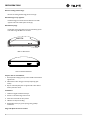
Service and Parts Manual
Section1- General Information
INTRODUCTION
Three generations of pride and quality manufacturing and design
improvements are built into all U-Line products. The result: U-Line
leads the market with innovative technology and superior craftsman
ship.
This manual contains specific instructions for servicing the U-Line
Product families.
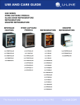
Product Families
Refrigerators
Wine Captains
Beverage Centers
Combination Ice Makers
Clear Ice Makers
Manual Defrost Ice Makers
ADA Units
Outdoor Units
Freezers
POTENTIAL PROBLEMS WITH
HFC-134A
This service manual has been written to cover products
manufactured with HFC-134A. HFC-134A compressors receive a
synthetic based ester oil charge. The hygroscopic (water attraction)
property of ester oil is many times greater than the mineral oils
previously used with CFC-12. High system moisture causes the
formation of acids and alcohol which can damage the compressor.
Systems should not be left open for more than fifteen (15) minutes at
any time as humidity from the air will enter the system. To ensure
system dehydration, the system should be pulled down to 100
microns and vacuum pump oil (mineral oil) must not be allowed to
enter the system.
Cleanliness of the system is extremely important. The presence of
residues (chlorinated or greasy residues, mineral oil, or impurities)
can lead to capillary tube restrictions, oil return problems and
compressor damage. Do not use flux on brazed joints.
IMPORTANT
Check for the latest service related information at
U-LineService.com. The Technical Knowledge base is
continuously updated and can be accessed anytime. Each
U-Line product has a unique method of installation, but it is
consistent with U-Line’s methods and requirement. Follow
the installation guidelines for the U-Line product you are
installing.
1
Section1- General Information
2
Section1- General Information
SAFETY PRECAUTIONS
IMPORTANT
•
•
•
PLEASE READ all instructions completely before attempting to service the unit.
•Proper installation procedures must be followed if this unit is
being initially installed, or is moved to a new location after being
in service. An INSTALLATION GUIDE for your unit, providing
complete installation information is available from U-Line Corporation directly, and must be consulted before any installation
is begun. U-Line contact information appears on the rear cover
of this guide.
•This unit requires connection to a grounded (three-prong),
polarized receptacle that has been placed by a qualified
electrician in accordance with applicable electrical codes.
•
•
WARNING
Failure to use the Anti-Tip Kit when it is included with the
product can cause serious personal injury. The Anti-Tip Kit
must be installed before the unit is used.
Safety Alert Definitions
Safety items throughout this guide are labeled with a Danger,
Warning or Caution based on the risk type.Warning means that
failure to follow this safety statement could result in serious personal
injury or death.
CAUTION
•
Use care when moving and handling the unit. Use gloves
to prevent personal injury from sharp edges.
•
If your model requires defrosting, DO NOT use any type
of heater to defrost. Using a heater to speed up defrosting can cause personal injury and damage to the inner
lining.
DANGER
Danger means that failure to follow this safety statement
will result in severe personal injury or death.
WARNING
Warning means that failure to follow this safety statement
could result in serious personal injury or death.
IMPORTANT
•
Do not lift unit by door handle.
•
Never install or operate the unit behind closed
doors. Be sure front grille is free of obstruction.
Obstructing free air flow can cause the unit to
malfunction and may void the warranty.
Failure to clean the condenser every three months
can cause the unit to malfunction. This could void
the warranty.
Allow unit temperature to stabilize for 24 hours
before use.
If you model requires defrosting, never use an ice
pick or other sharp instrument to help speed up
defrosting. These instruments can puncture the
inner lining or damage cooling unit.
Use only genuine U-Line replacement parts. Imitation parts can damage the unit, affect it operation or performance and may void the warranty.
CAUTION
•
Caution means that failure to follow this safety statement
may result in minor or moderate personal injury, property
or equipment damage.
•
General Precautions
•
Use this appliance for its intended purpose only and follow these
general precautions along with those listed throughout this guide.
•
DANGER
Never attempt to repair or perform maintenance on
the unit until the electricity has been disconnected.
Never remove the round grounding prong from the plug
and never use a two-prong grounding adapter.
Altering, cutting of power cord, removal of power cord,
removal of power plug, or direct wiring can cause serious injury, fire and/or loss of property and/or life and will
void the warranty.
Never use an extension cord to connect power to the
unit.
Always keep your working area dry.
RISK OF CHILD ENTRAPMENT. Before you throw away
your old refrigerator or freezer, take off the doors and leave
shelves in place so that children may not easily climb inside
WARNING
SHOCK HAZARD - Electrical grounding required.
1
Section1- General Information
U-LINE CORPORATION LIMITED WARRANTY
1.U-Line Corporation ("U-Line") warrants each U-Line product to be free from defects in materials and workmanship for a period of one year
from the date of purchase. U-Line further warrants the sealed system (consisting of the compressor, the condenser, the evaporator, the hot
gas bypass valve, the dryer and the connecting tube) in each U-Line product to be free from defects in materials and workmanship for a period
of five years from the date of purchase.
2.During the initial one year warranty period for all U-Line products U-Line shall: (1) repair any product or replace any part of a product; and
(2) for all Marine, RV and Domestic U-Line products sold and serviced in the United States (including Alaska and Hawaii) and Canada, U-Line
shall be responsible for the labor costs performed by a U-Line authorized service company, incurred in connection with the replacement of any
defective part. During years two through five of the warranty period for the sealed system, U-Line shall: (1) at U-line’s option repair or replace
any part of the sealed system; and (2) for all Marine, RV and Domestic U-Line products sold and serviced in the United States (including Alaska
and Hawaii) and Canada, U-Line shall be responsible for the labor costs incurred in connection with the replacement of any defective part of the
sealed system. All other charges, including transportation charges for replacements under this warranty and labor costs not specifically covered
by this warranty, shall be the responsibility of the purchaser. This warranty extends only to the original purchaser of the U-Line product. The
registration Card included with the product should be promptly completed by you and mailed back to U-Line or you can register on-line at
www.u-lineservice.com.
3.The following conditions are excluded from this limited warranty: damage caused by outdoor use; use of cleaners other than the
recommended stainless steel cleaners and U-Line Clear Ice Maker cleaner; installation charges; damages caused by disasters or acts of God,
such as fire, floods, wind and lightning; damages incurred or resulting from shipping, improper installation, unauthorized modification, or misuse/
abuse of the product; customer education calls; food loss and spoilage; door and water level adjustments (except during the first 30 days from
the date of installation); defrosting the product; adjusting the controls; door reversal; and cleaning the condenser.
4.U-Lines' Outdoor Limited Warranty, set forth in this Paragraph 4, shall apply to U-Line models deemed suitable for outdoor use by
Underwriters Laboratory ("UL") as noted in the U-Line Product Catalog, U-Line's website and/or on the serial tag located inside the product.
Exposure to temperatures below freezing may cause damage to the product. Damage resulting to the product (and/or the surroundings)
caused by this exposure is not covered under this warranty. Such models shall continue to be covered by the warranty terms set forth in
Paragraphs 1 and 2 above, to the extent such models:
A. Are subjected to temperatures between 50 and 100 degrees Fahrenheit. Although these products will function in ambient temperatures
below 50 degrees and above 100 degrees Fahrenheit, performance may decline. Performance degradation due to operating above or below the
designated ambient temperature range is not a manufacturing defect and any issues resulting from exposure to higher temperatures, such as
spoiled food or low ice production, are not covered under this warranty policy; and/or
B. Come into contact with rain by virtue of outdoor use. Exposure to other sources of water shall also cause this warranty to be void,
including flooding of the area in proximity of the unit greater than 1/8” deep in water, hurricanes, splashing of pool water, or directing a spray
from a hose or similar device into and around the unit.
5.If a product defect is discovered during the applicable warranty period, you must promptly notify either U-Line at P.O. Box 245040,
Milwaukee, Wisconsin 53224 or at 800-779-2547 or the dealer from whom you purchased the product. In no event shall such notification be
received later than 30 days after the expiration of the applicable warranty period. U-line may require that defective parts be returned, at your
expense, to U-Line's factory in Milwaukee, Wisconsin, for inspection. Any action by you for breach of warranty must be commenced within
one year after the applicable warranty period.
6.THIS LIMITED WARRANTY IS IN LIEU OF ANY AND ALL OTHER WARRANTIES, EXPRESS OR IMPLIED, INCLUDING ANY IMPLIED
WARRANTY OF MERCHANTABILITY OR IMPLIED WARRANTY OF FITNESS FOR A PARTICULAR PURPOSE, ALL OF WHICH ARE
DISCLAIMED. U-Line’s sole liability and your exclusive remedy under this warranty is set forth in the paragraphs above. U-Line shall have no
liability whatsoever for any incidental, consequential or special damages arising from the sale, use or installation of the product or from any
other cause whatsoever, whether based on warranty (express or implied) or otherwise based on contract, tort or any other theory of liability.
7.Some states do not allow limitations on how long an implied warranty lasts or the exclusion or limitation of incidental or consequential
damages, so the above limitations may not apply to you. This warranty gives you specific legal rights, and you may also have other rights which
vary from state to state.
2
Section1- General Information
PRODUCT LIABILITY POLICY
Field service technicians are authorized to make an initial assessment. If in the servicer’s judgment the damage is the result of a product defect,
the product would be removed and returned to U-Line in an unaltered condition. The dealer would then be authorized to permanently replace
the end-user’s product at no cost to the end-user. Please call U-Line immediately at 800-779-2547 to initiate the RA and product exchange
process.
If in the servicer’s judgment the damage is the result of installation issues (water connection/drain, etc.), the consumer would be so notified and
the correction would be made by the servicer or installer without requiring removal of the product. Any claim for damages should be directed
to the original installer.
Any U-Line unit involved in an alleged property damage claim must remain unaltered and unrepaired, for evaluation. No service or repairs
should be performed on any unit suspected to be involved in a property damage situation. If a unit has been altered or repaired in the field prior
to U-Line’s evaluation, any claim for damage may be declined.
If the unit in question is a U-Line CLR or CLRCO with a drain pump, both the unit and the drain pump (regardless of the manufacturer) must
be returned to U-Line Corporation.
To complete the damage claim process for the customer, please obtain the following and forward to U-Line at [email protected], fax
to 414-354-5696 or mail to the address below.
Pictures of the unit, installation and any alleged property damage.
Inquire when the problem first appeared, any prior problems with the product and provide a brief description of the
alleged damages.
To expedite the claim process, U-Line will need two damage repair estimates.
Reference the RA number and customer name when providing this information.
If a unit is returned to U-Line, this evaluation will take approximately ten business days. No field service company is authorized to
perform this evaluation. When a Return Authorization Number is issued, and the unit has been boxed in a U-Line carton, U-Line should be
contacted and then will make arrangements for shipping, or designate a truck line to have the unit shipped freight collect.
If U-Line’s evaluation finds the unit, (or U-Line P60 pump) to be defective, causing the property damage, the damage claim will be reviewed by
the U-Line Customer Assurance Department.
If U-Line’s evaluation finds the unit not to be defective, does not repeat a failure or does not leak any water from the U-Line unit or U-Line P60
pump, all claims for damage will be declined.
When a product evaluation is needed, it is the customer’s responsibility to assure that the unit is returned for evaluation. If the customer fails to
do so, or has the unit repaired in the field prior to U-Line’s evaluation, any claim for damage will be declined.
8900 N. 55th St. • P.O. Box 245040
Milwaukee, WI 53224-9540
414/354-0300 • Fax: 414/354-7905
Website: www.u-line.com
Leaders In Quality Undercounter Refrigeration
3
Section1- General Information
IMPORTANT
Warranty claims must be filed within 60 days after the completion of the service call
Warranty Claims Procedure
When submitting claims for warranty payment, please follow these guidelines.
You can use any form you would normally use to bill your customer
(your own computer generated form, Narda, USA, etc.). Claims can
also be filed on-line at www.u-lineservice.com.
The model and serial number MUST be on the claims. Claims will
not be paid without a model and serial number.
If you used a part in your repair, you MUST put the part number, the
invoice number and where the part came from. Claims will be
returned without this information.
Proof of Purchase
Proof of Purchase and/or Proof of Install is an important part of the
warranty claim process. Sometimes it is difficult to obtain a proper
Proof of Purchase/Proof of Install for a number of different reasons:
• The customer does not have a copy (only the original).
• The customer has only their copy of the final Walk Through or
sign-off of new construction.
• Other valid reasons that prevent your technician from leaving the
job site with a suitable Proof of Purchase/ Proof of Install.
We understand the problem and have modified our Proof of Purchase
policy to help you in these situations.
Effective immediately, if a copy of the Proof of Purchase/Proof of
Install is not available at the site, the technician should record the
following information on the Labor Invoice:
• The name of the selling Dealer
If you work on more than one unit per service call please submit a
separate claim for each unit.
• The date of purchase/installation
We track all defects through warranty claims, so please be specific on
what the repair was. If it is a system leak, please specify where the
leak was.
• The type of document they saw, i.e. Store Receipt, Closing Papers,
Sign-Off of Building Permit, Final Walk Through, etc.
Please be sure the claim is legible. If the claim form cannot be read, it
will be returned, unpaid.
Remember: Door and water level adjustments are 30 day
warranties only.
If you are changing out a unit please supply the model and serial
number of both units (the unit being replaced and the new unit) and
the R.A. number.
Occasionally the customer does not return their warranty cards. In
this case we use the date the unit was shipped to our distributor for
a beginning warranty date. This may cause the claim to be rejected
for a proof of purchase. If you want to check on a purchase date, you
may contact the U-Line Corporation Customer Assurance
Department at 1-800-779-2547. This will allow you to get a proof of
purchase, if needed, before you submit the claim.
At U-Line, parts and labor claims are paid separately. Included in
labor are freon and recovery charges, all other parts are handled by
the parts department. We require that some parts be returned to us,
so we may return them to our vendor. It will be noted on your
packing list if we require you to return the part. If a part is to be
returned please include a copy of the packing list and a copy of your
claim. If the part was purchased at one of our part distributors, you
must handle the part warranty with that company. For labor payment
please send a readable copy of your claim to U-Line Corporation,
P.O. Box 245040, Milwaukee WI, 53224-9540, or fax it to 414-3545696. Claims can also be filed on-line at www.u-lineservice.com.
4
• The Order or Invoice number (if available)
If we have this information on the Labor Invoice, and we have the
other information that is needed (correct Serial Number, type of
repair, time spent on repairs, parts used in the repair,
invoice number for the part, etc.), we will be able to process the
invoice for you in a timely manner.
Section1- General Information
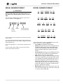
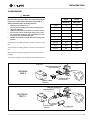
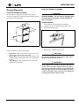
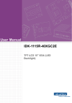
SERIAL NUMBER FORMAT
MODEL NUMBER FORMAT
IMPORTANT
U - 2275 DWRW OL - 00
Starting October 2009, U-Line Corporation went to a 13
digit serial number. Anything before that date will have 12
digits.
U-LINE
The serial number is divided into four segments. A typical serial
number is 0914997-11-0005. (Figure 1)
U - CO
U-LINE
0914997-11-XXXX
Month
Shop
Order
Number
FAMILY
FAMILY
Factory Internal
Control Number
1175
PRODUCT
SERIES
SPECIAL
ORDER
S - 00
COLOR
SPECIAL
ORDER
U - 2175 RC GOL - 00
U-LINE
The first two digits of the first segment, 09, represents the year the
unit was made.
The next two digit segment, 11, represents the month the unit was
made.
SPECIAL
ORDER
S - 01
COLOR
2115
FAMILY
PRODUCT
SERIES
FAMILY
U - CLRCO
The next four/five digits of the first segment, 14997, represent the
shop order number. Order number 14997 is assigned for the Model
CLRCO2175B-40 units.
COLOR
PRODUCT
SERIES
ULN - BI
U-LINE
Year
PRODUCT
SERIES
U-LINE
FAMILY
COLOR
2175
PRODUCT
SERIES
SPECIAL
ORDER
S - 41
COLOR
SPECIAL
ORDER
A typical model number would be, U-2175RCGOL-00. The model
number is broken into 5 segments. (Figure 2)
•
•
The last four digit segment, XXXX, is a factory internal control
number used at U-Line Corporation.
•
•
•
U- or ULN- This signifies a U-Line Product.
Family The family is the type of unit. Currently there are
nine families. Refrigerators, Wine Captains, Beverage
Centers, Combo Ice Makers, Clear Ice Makers, Manual
Defrost Ice Makers, ADA Units, Outdoor Units and
Freezers.
Product Series Each family can include different product
series. U-Lines current product series includes 95, 98,
SP18, 1095, 29, 10xx, 11xx, 21xx and 22xx.
Color The color segment includes color along with information that is important to the unit and the way it is used.
As an example, the model U-2175RCGOL-00, is part of
the family of refrigerators, product series 2175. The “C”
following the “R” tells us this is a convection cool unit
with an evaporator fan motor. The “GOL” tells us the unit
is black with a glass door requiring an overlay panel. (all
glass door overlay units are black)
Special Order These numbers tells us if the unit is a SS
door with a left hand hinge, (01) a CLR with a pump, (40)
or a marine or RV product. (03)
5
Section1- General Information
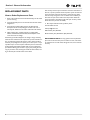
REPLACEMENT PARTS
How to Order Replacement Parts
1. Refer to Service Parts and locate the illustration(s) for the model
you are servicing.
2. Locate the desired part to be serviced and note the item number
assigned to it.
3. Locate the item number within the parts list. Note the full
description and the corresponding part number. If this is for a
warranty unit, indicate and record the model and serial numbers.
4. When ordering parts, it will be necessary to supply Model
Number, Serial Number, Part Number, Part Description and in
some cases Color or Voltage.
All warranty parts will be shipped at no charge as long as warranty
status has been confirmed. If we require that a part be returned to Uline, you will be informed at the time the order is placed. It will be
noted on your packing list if we require you to return a part or if you
may field scrap it. If U-Line requires a defective part to be returned, a
prepaid shipping label will be included with your new replacement
part. When returning parts enclose a copy of your packing list and a
copy of your labor claim, showing the model and serial number, and
tag or label the part with the nature of the defect.
6
Our warranty records may not match the customer's information. In
this case, a proof of purchase will be required. If you do not have the
proof of purchase at the time the order is placed, the part will be
sent net 15 days, charged to a Visa or Master Card or COD if you
don't have an open account with U-Line Corporation. When the
proof of purchase is provided, we will credit your account (a check
will be sent if the part was sent COD).
5. Parts may be ordered on-line, by FAX or phone:
www.U-LineService.com
[email protected]
FAX Number (414) 354-7905
Phone Number (414) 354-0300 or (800) 779-2547;
REPLACEMENT PARTS: Use only genuine U-Line replacement
parts. The use of non-U-Line parts can reduce ice rate, cause water
to overflow from ice maker mold, damage the unit, and can void the
warranty.
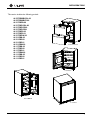
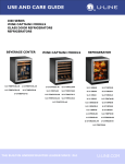
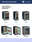
REFRIGERATORS
This section includes the following models:
•U-2275DWRCOL-00
•U-2275DWRCS-00
•U-2175RCB-00
•U-2175RCGOL-00
•U-2175RCGS-00
•U-2175RCGS-01
•U-2175RCS-00
•U-2175RCS-01
•U-2175RCW-00
•U-2115RB-00
•U-2115RS-00
•U-2115RS-01
•U-2115RW-00
•U-1175RB-00
•U-1175RS-00
•U-1175RS-01
•U-1175RW-00
•U-1115RB-00
•U-1115RS-00
•U-1115RS-01
U-2275DWRCGS-00
U-2175RCS-01
U-2115RB-00
U-1175RB-00
1
REFRIGERATORS
TROUBLESHOOTING
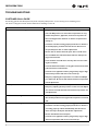
CUSTOMER CALL GUIDE
The following guide has been developed to help answer frequently asked questions. It can be used by persons scheduling service
calls. These are things the customer should consider before scheduling a service call.
Concern
The unit is not cold enough.
Response
• Are you familiar with the factory temperature specifications for
your unit? Many factors can cause these temperatures to vary;
ambient temperature, application, amount of use (number of
times and length of time the door or drawers are opened and
closed), etc
• Is the door or drawers sealing properly? If the door or drawer is
not sealed properly, it allows heat into the unit. U-Line’s warranty is 90 days for door or drawer adjustments.
• Has the door or drawers been left open? The 21 and 22 series
have an audible tone if the door/drawer has been left open for
longer than 5 minutes.
• Is the condenser clean? U-Line’s warranty does not cover cleaning the condenser.
• Is the unit behind closed doors or the grille restricted? The front
grille must be free of obstruction.
• Is the unit in an application of heavy usage? Heavy usage or high
ambient temperatures will cause a unit to frost up.
• Did you try adjusting the temperature to a colder level? Adjust
to a colder level. Be sure to allow 24 hours between temperature
control adjustments.
Temperature is too cold.
• Check actual temperature versus set-point.
• Did you try adjusting the temperature to a warmer level? Adjust
to a warmer level and allow 24 hours between temperature control adjustments.
Product is freezing.
• What is the temperature set at?
• Do not allow products to lean against the evaporator at the back
wall.
The unit is frosting up.
• Are you familiar with the defrost technology of your unit?
• Is the door or drawers sealing properly? If the door or drawer is
not sealing properly, it allows heat/humidity into the unit. ULine’s warranty is 90 days for door/drawer adjustments.
• Has the door/drawers been left open?
• Is the unit in an application of heavy usage? Heavy usage or high
ambient temperatures will cause a unit to frost up.
2
REFRIGERATORS
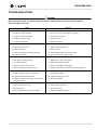
TROUBLESHOOTING
DANGER
Never attempt to repair or perform maintenance on the unit until the main electrical power has been
disconnected from the unit.
Cause
Remedy
Compressor overheating
1. Condenser air flow restricted.
1. Remove restriction (clean condenser and grille).
2. Condenser fan blade obstructed.
2. Remove blade restriction
3. Condenser fan motor stalled.
3. Replace fan motor
4. Compressor inoperable.
4. Replace compressor
Compressor will not stop operating.
1. Temperature set too cold.
1. Adjust temperature warmer.
2. Control inoperable.
2. Replace control.
3. Control sensing bulb not sensing temperature.
3. Check bulb/thermistor for location and ohms.
4. Evaporator fan stalled.
4. Remove obstruction or replace motor.
Excessive frost buildup.
1. Door gasket not sealing properly.
1. Adjust door or replace door gasket.
2. Door out of alignment
2. Adjust door hinges/pivot plates.
3. Light stays on when door is closed.
3. Repair or adjust light bracket/magnet.
4. Warm air leaking into cabinet from back.
4. Seal holes in the foam to prevent warm air entering the unit.
Noisy.
1. Copper refrigeration tube touching cabinet.
1. Carefully adjust tubing.
2. Evaporator fan blade touching cover.
2. Adjust fan mounting or shroud.
3. Condenser fan obstruction (wiring, foam insulation,
packaging material).
3. Remove obstruction.
Ice Buildup in drain trough or drain problem
1. Obstructed drain cup or tube.
1. Check and clear drain tube.
2. Kinked drain tube.
2. Reroute drain tube.
3. Drain trough spout and drain cup not aligned
3. Align drain trough and drain cup.
3
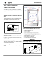
REFRIGERATORS
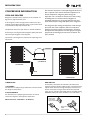
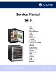
COMPRESSOR INFORMATION
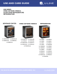
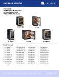
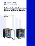
COOLING PROCESS
Refrigerant is pumped from the compressor to the condenser as a
high pressure, high temperature vapor.
As the refrigerant cools in the high pressure condenser, the vapor
condenses to liquid. During this phase change, a great amount of heat
is rejected with the help of the condenser fan.
The liquid then flows to the dryer where it is strained and filtered.
From the dryer, the refrigerant flows through the capillary tube which
meters the liquid refrigerant to the evaporator.
The reduction of pressure on the liquid refrigerant causes it to
boil or vaporize until it reaches saturation temperature. As
the low temperature refrigerant passes through the
evaporator coil, it continues to absorb a lot of heat, causing
the boiling action to continue until the refrigerant is
completely vaporized. It is during this phase that the most
heat is absorbed (the cooling takes place) in the refrigerator.
The refrigerant vapor leaving the evaporator travels through
the suction line to the compressor inlet. The compressor
takes the low pressure vapor and compresses it, increasing
both pressure and temperature. The hot high pressure gas is
pumped out the discharge line and into the condenser. The
cycle continues
The pressure of the refrigerant is reduced to the evaporating or low
side pressure.
COMPRESSOR
CONDENSER
DRYER
EVAPORATOR
THERMISTORS
1100 MODELS
One thermistor is employed. A type 2 thermistor is used to measure
the refrigerator temperatures.
2100/2200 MODELS
Two thermistors are employed. Type 2 thermistors are used to
measure the refrigerator and evaporator temperatures.
White thermistor - 5000 Ohms - 70° Ambient
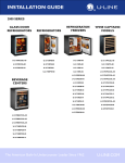
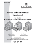
REED SWITCH
A reed switch is mounted to the underside of the cabinet and a
magnet is mounted to the door. When the door is closed the magnet
trips the switch which turns the light and display off. If the door or
drawers are left open for longer than 5 minutes, the switch will
trigger an error code (E3 -1100 models) and sets an audible warning
(2100/2200 models). The drawer model has a set in each drawer.
Magnet away
from switch
(closed contacts)
Magnet close to
switch
(open contacts)
4
REFRIGERATORS
COMPRESSORS
DANGER
Electrocution can cause death or serious injury. Burns
from hot or cold surfaces can cause serious injury.
Take precautions when servicing this unit.
•
•
•
•
•
Disconnect the power source.
Do not stand in standing water when working around
electrical appliances.
Make sure the surfaces you touch are not hot or frozen.
Do not touch a bare circuit board unless you are wearing an anti-static wriststrap that is grounded to an electrical ground or grounded water pipe.
Handle circuit boards carefully and avoid touching components
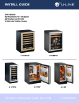
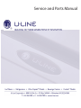
5400-S
70077-S
EMI30HER
EMU30HSC
Voltage
115
115
Frequency
60
60
LRA
9.8
5.5
FLA
1.2
1.0
Start Winding
21.20
7.0
Run Winding
7.9
8.4
Overload
5411
71009
Relay
5412
71010
Capacitor
N/A
71013
To measure the start winding resistance, measure across the C and S
pins.
To measure the run winding resistance, measure across the C and R
pins.
Also check S to R and you should get the sum of the run and start
windings.
To ensure the windings are not shorted, check the S and R to ground.
EMI ER
OVERLOAD PROTECTOR
EMI30HER
5400-S
C
STARTING RELAY
R
S
RELAY COVER
UL183-3
OVERLOAD PROTECTOR
STARTING RELAY
EMU30HSC
70077-S
C
S
RELAY COVER
R
CAPACITOR
UL183-3.1
5
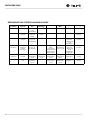
REFRIGERATORS
REFRIGERATION SYSTEM DIAGNOSIS GUIDE
6
System
Condition
Suction
Pressure
Suction
Line
Compressor
Discharge
Condenser
Capillary
Tube
Evaporator
Wattage
Normal
Normal
Slightly below
room
temperature
Very hot
Very hot
Warm
Cold
Normal
Overcharge
Higher than
normal
Very cold may frost
heavily
Slightly warm
to hot
Hot to warm
Cool
Cold
Higher than
normal
Undercharge
Lower than
normal
Warm near room
temperature
Hot
Warm
Warm
Extremely cold
near inlet outlet below
room
temperature
Lower than
normal
Partial
Restriction
Somewhat
lower than
normal in vacuum
Warm near room
temperature
Very hot
Room
Extremely cold
Top passes
temperature
near inlet warm lower passes (cool) or colder outlet below
room
cool (near room
temperature
temperature
backing up
due to liquid
Lower than
normal
Complete
Restriction
In deep
vacuum
Room
temperature
(cool)
Room
temperature
(cool)
Room
temperature
(cool)
Room
temperature
(cool)
No
refrigeration
Lower than
normal
No Gas
0 PSIG
to 25"
Room
temperature
(cool)
Cool to hot
Room
temperature
(cool)
Room
temperature
(cool)
No
refrigeration
Lower than
normal
REFRIGERATORS
2275, 2175, & 2115 MODELS
CONVECTION COOLING
Some models have an interior 12 Volt fan motor to help stabilize
temperatures and pull down quicker. The evaporator cover is easily
removed.
Please Note
Convection Cool units are available with solid or glass
doors
The evaporator fan motor is plugged directly onto the main board
and is powered by the logic of the board and not by a relay.
12 VOLT EVAPORATOR FAN
TO
DISPLAY
FAN
J3
PLUG
CONTROL
BOARD
The evaporator fan is delayed for 1 minute after compressor starts to
prevent warm air circulation.
Fan will run 1 minute longer than compressor to use extra cooling
capacity remaining.
Fan will turn off when the door is opened.
When door is closed fan will always run for 1 minute to recirculate
air and aid clearing any fogging of door.
REPLACING THE EVAPORATOR FAN
•
•
•
•
•
•
•
•
•
Remove the back panel.
Unplug the evaporator fan motor.
Remove the shelves.
Remove 2 screws at the top of the evaporator cover.
Remove 2 screws at the bottom of the evaporator cover.
Carefully remove the cover with fan, being careful not to pull
wire out of fan.
Remove 4 screws from inside of cover.
Remove evaporator fan and replace.
To assemble replace parts in reverse order
IMPORTANT
Do not plug fan in until evaporator cover is in place. The
wire could be pulled off of the fan motor.
Multiple door openings can cancel these modes. To reset these
modes, allow the unit to stand unopened for approximately 30
minutes.
1
REFRIGERATORS
2275, 2175, & 2115 MODELS
ELECTRONIC CONTROL
IMPORTANT
All relay and thermistor information can be found on the
Electronic Control Quick Guide.
THERMISTORS
There are 3 thermistors on the 2275 refrigerator models and 2
thermistors on the 2175 & 2115 refrigerator models.
•
Thermistor 1 (T1) is on the right hand wall and is used to maintain temperature in the refrigerator. Set point is between 34°
and 45°.
•
Thermistor 2 (T2) is attached to the back side of the evaporator
plate and is used during defrost. Normal defrosting is based on a
time and temperature scale. Defrost ends if the evaporator
thermistor reaches stop point (42°) or maximum time, (90 minutes) whichever comes first.
•
On the 2275DWR the 3rd thermistor (T3) monitors the ambient temperatures. The mullion heater is energized whenever the
T3 temperature falls below 90°
DANGER
Electrocution can cause death or serious injury. Take
precautions when touching a bare circuit board. Wear
an anti-static wrist strap and ground it to an electrical
ground or grounded water pipe. Handle circuit boards
carefully and avoid touching components.
NOTE: When touching icon combinations in which you hold one icon and
press another icon three times, it is important to carefully follow this
procedure.
1. Hold the desired icon ensuring the light above the icon is lit.
2. Immediately press the other icon three times, ensuring it lights up
each time.
3. Release the held icon only after releasing the pressed icon for the
third time.
Except as noted, these functions are available on all models.
VIEWING ACTUAL TEMPERATURE
ON/OFF
There are two modes to view temperature. In viewing temperature
in these modes, any offsets are taken into account. This means that if
you place a thermistor in a known temperature, let’s say ice water, it
may not read the 32°F that you would assume. If the control offset
was preset at -3°F while you placed the thermistor in an ice bath, the
actual thermistor reading when viewing actual temperature would
read 35°F. In the unit this would cause the cabinet to push itself 3°
cooler. To view pure thermistor readings, you must go into the
service menu and choose the correct option.
The ON/OFF mode allows the unit to be turned on and off via the
iconpad. To do this, hold the icon for approximately 15 seconds until
the “F” begins to flash. Release and the unit will switch modes. In
the OFF position the cabinet light will remain operational. This mode
does not disconnect power from the circuit board so it is still “live.”
To view T1 (normally refrigerator temperature) hold the WARMER
icon for approximately five seconds until the “F” flashes. Release and
the display will show the corrected refrigerator temperature.
Checking a completely unloaded cabinet may result in inaccurate
temperatures.
To view T2-T4, hold both the WARMER and COLDER icons for
approximately five seconds until the number two appears. Release
the icons and the display will cycle through thermistors 2-4 and their
accompanying readings. If a thermistor is not used on that particular
model, it will show “0” and if the thermistor is not working, it will
show an error code.
ADJUSTING THE SET-POINT
To adjust the set-point press and release either the WARMER or
COLDER icon. This will start the set-point flashing. While in this
mode you can adjust the set-point warmer or colder until the desired
temperature is reached. The factory recommended set-point is 38°F
for refrigerators. When adjustment is complete, stop touching the
display and the set-point will be saved in approximately five seconds.
CHANGING FROM FAHRENHEIT TO CELSIUS
To change the displayed temperature from °F to °C, hold the LIGHT
icon and press the down arrow three times. This will change all
values to °C. When the icon combination is accepted the control will
beep once and change values.
THERMISTOR OUTAGE
If the refrigerator thermistor (T1) fails, the unit will continue to
operate based on a preset time interval of 10 minutes on and 30
minutes off. The display will show “ER.”
If the evaporator thermistor (T2) fails, the unit will operate except it
will defrost solely on time and ignore the temperature reading. The
display will show “ER.”
If the ambient thermistor (T3) fails, the unit will always have the
mullion heater energized. The display will show “ER.”
1
REFRIGERATORS
SHOWROOM MODE
This mode is designed to show units in a display environment. When
in this mode the only functions will be the control and cabinet lights.
The compressor, fans, etc. will not operate. To enter this mode hold
the down arrow and press the LIGHT button three times. When
entered, the unit will beep once and the degree symbol will begin to
flash. When the degree symbol is flashing the unit will allow the use
of the control for demonstrations.
On early models, after not touching the unit for one minute the
display will begin to “snake” around. This is meant to alert you the
unit is in showroom mode.
On later models, the degree (°) flashes.
The unit can be left in this mode indefinitely. If you again want to
demo the control, touch any icon and the degree symbol will begin to
flash. To exit this mode: If using software version 2.8, this mode will
exit automatically when the unit is unplugged. If using software
version 2.9, this mode needs to be exited by the same icon
combination as used to enter the mode.
SERVICE MODE
This mode has 27 different options available for service diagnostics.
To enter the mode hold the WARMER button and press the LIGHT
button three times. The display will show “0” and the board will beep
once. When in this mode the WARMER and COLDER buttons will
act as up and down arrows to select the desired option. The LIGHT
button is the ENTER button and will enter a function. If changing a
function, you must press the LIGHT button again to retain the
changed setting. To exit the service mode, scroll to option 99 and
press the LIGHT button. After five minutes of not touching any
buttons the mode will also exit automatically.
BLACKOUT MODE
Hold the LIGHT button for 10 seconds until the °F starts flashing.
When released, the unit will beep once and the display and cabinet
light will shut off. The unit will continue to maintain temperature in
the cabinet. To cancel this mode, hold the LIGHT button again for
about 10-12 seconds.
FORCED DEFROST
This will allow the unit to defrost quickly. For R and WC units, this is
just an off cycle. For units with hot gas defrost the unit will enter a
hot gas defrost per the specification. Hold the LIGHT button and
press ON/OFF three times. The unit will beep once when entering
this mode. To exit this mode either do the same button combination
or turn the unit off via the display.
RELAY STATUS
To check to see which relays are currently operating, hold the
COLDER button and press the ON/OFF button three times. When
entering the sequence, keep the COLDER button pressed until you
completely release the ON/OFF button for the third time. The
display will cycle through a series of numbers to tell which relays are
energized. For example, if the unit was cooling the bottom drawer
the display would show 11 20 31 40 50 61 70. The first number is the
relay number. In the second number, 1 means ON and 0 means OFF.
The relay information can be found in the Electronic Control Quick
Guide.
2
REFRIGERATORS
SERVICE MODE
Enter the service menu by holding up arrow and pressing LIGHT
three times. Select option 1 to 27 with the up and down arrows. To
enter the option, press the LIGHT button. You must press the
LIGHT button to retain the changed setting before going to the next
option.
10. Adjust thermistor 1 offset—10 to +10F
This allows calibration of the sensor to cabinet for abnormal
operations. By adjusting this number colder you can change the
average cabinet temperature to a colder value.
11. Data download
Along with the separate ESPY software you can download the
rolling data file.
When entering service mode all other modes are cancelled and the
unit will stop operating. When exiting service mode the unit will
begin to operate normally, however the four-minute compressor off
cycle still applies.
12. Clear error log
1. Light all LED segments.
13. Clear download memory
This will illuminate all the LEDs on the board to ensure they work
properly.
2. Thermistor 1 status—Temperature, E1, or E2.
This will show the pure thermistor reading with no offsets taken
into account. When placed in ice water this thermistor should
read 32°F in this menu option.
3. Error Log
A list of the errors in the order they occurred will scroll once on
the display. Repeat if desired. Once viewed perform option 12 to
clear the errors from memory.
4. Defrost information
Displays the number of defrosts that have occurred in the past 24
hours.
5. Compressor runtime based on last cycle
This will show the number of minutes the compressor has run in
the prior cycle (or current cycle if the compressor was running
when service mode was entered).
6. Defrost length adjustment—up to 99 minutes
The length of the defrost can be adjusted up to 99 minutes long.
The other defrost parameters still apply. Lengthening a defrost
may cause higher than normal temperatures in the refrigerator
section.
7. Light switch 1 status—0 or 1
This will tell if the light should turn off with the door switch or
not. At the “0” reading the light should be off with the door
closed and on with the door open. At the “1” reading the light
stays on always.
8. Display toggle status—0 or 1
This will tell if the display should turn off with the door switch or
not. At the “0” reading the display should be off with the door
closed and on with the door open. At the “1” reading the display
stays on always.
Perform this operation after checking the errors.
Clears the rolling data file if desired.
14. Model number displayed
Displays the two-digit model number of the specific unit.
15. Adjust thermistor 1 differential
This number should not be adjusted.
16. Adjust thermistor 2 offset
This allows calibration of the sensor to cabinet for abnormal
operations. By adjusting this number colder you can change the
average cabinet temperature to a colder value.
17. Adjust thermistor 3 offset
This allows calibration of the sensor to cabinet for abnormal
operations. By adjusting this number colder you can change the
average cabinet temperature to a colder value. Not available on
Rs, WCs or CLR2160.
18. Adjust thermistor 4 offset
This allows calibration of the sensor to cabinet for abnormal
operations. By adjusting this number colder you can change the
average cabinet temperature to a colder value. Not available on
Rs or WCs.
19. Thermistor 2 status
This will show the pure thermistor reading with no offsets taken
into account. When placed in ice water this thermistor should
read 32°F in this menu option.
20. Thermistor 3 status
This will show the pure thermistor reading with no offsets taken
into account. When placed in ice water this thermistor should
read 32°F in this menu option.
21. Thermistor 4 status
This will show the pure thermistor reading with no offsets taken
into account. When placed in ice water this thermistor should
read 32°F in this menu option.
9. Restore factory defaults
This will restore the default set-point, defrost and offset values.
3
REFRIGERATORS
22. Automatic toggle through relays switch on and off
Each relay can be turned on and off individually to determine
whether or not the board and component are operating. If a
component is suspected of not operating correctly, you can run
through this sequence to ensure each component is turning on
and off through the board correctly. This will cycle every relay on
and off showing 10 (on) 11(off), 20 (on) 21(off) ….through all the
relays. If a component fails to turn on when the relay does, you
can verify if there is voltage present by using a voltmeter to check
the board output. The relay information can be found on the
Electronic Control Quick Guide.
ERROR CODES
IMPORTANT
All errors or combinations show up as ER alternating with
SP. P1 will alternate with SP or ICE for models 67/68. E3 and
E10 both have audible alarms. P1 does not have an audible
alarm.
E1
Thermistor 1 is open. Not available on CLR2160.
E2
Thermistor 1 is shorted. Not available on CLR2160.
The evaporator fan motor is plugged directly onto the main
board and is powered by the logic of the board and not by a
relay.
E3
Main door or bottom drawer is open longer than 20 minutes.
23. Defrost interval adjust. 3 to 24 hours
E5 Thermistor 1 out of range + 10°F for more than 12 hours. Not
available on CLR2160.
IMPORTANT
This will adjust the interval between defrosts from 3 to 24 hours.
Adjusting from the factory settings may cause undesired
temperature in the refrigerator section.Adjust thermistor 2 setpoint. Only available on CO2175F, CO2175DWR, CLR2160 and
CLRCO2175.
24. Adjust thermistor 3 set-point. Only available on
2275DWRWS.
25. Adjust thermistor 4 set-point. Only available on
2275DWRWS.
26. Show software revision
This will toggle between main and display board software
revision. The main board number will be accompanied by the
degree symbol.
E4 Compressor had 100% runtime between two defrost cycles.
Does not show on display—only in error log.
E6 Thermistor 1 out of range -10°F for more than 12 hours. Not
available on CLR2160.
E7
Thermistor 2 open or shorted. Not available on 2175RF.
E8 Thermistor 3 open or shorted. Not available on Rs, WCs or
CLR2160.
E9
Thermistor 4 open or shorted. Not available on Rs, WCs.
E10 Top drawer is open longer than 20 minutes. Only available on
drawer models.
P1 Pump circuit open. Only available on CLR2160 or
CLRCO2175 models with P60 pump.
E11 EE Memory error.
4
REFRIGERATORS
THERMISTOR LOCATIONS
Model
Thermistor 1
Thermistor 2
Thermistor 3
Thermistor 4
Door Switch 1 Door Switch 2
2175R
REF
EVAP
N/A
N/A
Yes
N/A
2115R
REF
EVAP
N/A
N/A
Yes
N/A
2175/2275
DWRR
REF
EVAP
Ambient
N/A
Bottom Drawer
Top Drawer
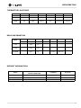
RELAY INFORMATION
Model
Relay 1
Relay 2
Relay 3
2175R
Light
Compressor/
Fan
2115R
Light
Compressor/
Fan
2175DWRR
2275DWRR
Light 1
Compressor/
Fan
Relay 4
Relay 5
Relay 6
Pan Heat
Mull Heat
Relay 7
DEFROST INFORMATION
Model
Hours Between Defrost Time
(Runtime) (Adjustable)
Length/min
Stop Point
2175R
6
90
42°
2115R
6
90
42°
2175/2275DWRR
6
90
42°
5
Hold
or
Adjust Refrigerator Set-point
2275DWRWC adjust lower drawer
set-point
Adjust zone set-points 2275ZWC
View actual temperature (T1)
View actual temperature (T2 – T4)
Toggle F – C
Toggle Showroom Mode
Service Mode
Display Toggle
Glass door/drawer models only
Blackout Mode
Clean Cycle
Icemaker Off Mode
Forced Harvest
Forced Refrigerator Defrost
Ice Thickness Adjustment
Temporary Shutdown (Office Mode)
Relay Status
Change Mode Number (with jumper)
3
4
5
6
7
8
9
10
11
12
13
14
15
16
17
18
19
20
Rev. 9 4/2010
Hold
or
Toggle Lights
2
Touch to
show zone
Hold
Repeat to exit
Hold light icon for 10 seconds to exit
Turns display on/off with door closed
See back of card for details
To exit, arrow up to 99 & touch light
Repeat to exit mode
WC’s will scroll top/middle/bottom temperatures
Use warmer/colder to adjust temperature while small LED
is flashing
Touch up/down once to get into set mode, touch light, for
bottom drawer then touch up/down to adjust
Touch once to get into set mode,
then touch to adjust
=:&XVHWKHOHIWWRHQWHURUH[LWPRGHV
Hold
Hold
Hold
Follow the instructions on the back of this card.
Relay number with 1 or 0 to indicate on/off.
In this example relay 2 is on, relay 3 is off.
Icemaker will automatically turn back on
in three hours
Use warmer/colder to adjust.
Touch light icon to exit.
Audible alert when entering this mode
30
IC E
Light normally goes on/off with door opening. Pressing light
button will turn interior light on for 4 hours, then it will turn off.
The CLR2160 will show
&RPPHQWV
Hold
21
Display (and cabinet light) not operable in
blackout mode
Degree symbol flashes
or
Scrolls through T2–T4 Flashing
Flashing
Bottom line of E flashes
Flashing
or
'LVSOD\
Audible alert when entering this mode
Touch to set temp
or
or
Release when unit beeps
7RXFK
Hold
Hold
Hold
Hold for 10 seconds
Hold
Hold
Hold for 5 seconds
Hold for 5 seconds
or
Glass door/drawer
models only
Hold 10 Seconds
On/Off
7RXFK
1
7DVN
REFRIGERATORS
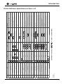
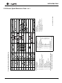
2100 & 2200 Series Quick Reference Card 1 of 2
1
2
75
76
77
78
79
80
81
82
84
73
74
86
88
220 Volts
'HVFULSWLRQ
DOWHUQDWHVZLWK
VHWSRLQWGLVSOD\
Thermistor #1 open
Thermistor #1 shorted
Door or bottom drawer open longer
than 20 minutes
Thermistor #1 out of range (+10˚)
for more than 12 hours
Thermistor #1 out of range (-10˚)
for more than 12 hours
Thermistor #2 open or shorted
Thermistor #3 open or shorted
Thermistor #4 open or shorted
Top drawer open longer than
20 minutes
EE Memory Error
Pump circuit open due to high water
level in ice bin
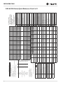
(UURU&RGH
E1
E2
E3
E5
E6
E7
E8
E9
E10
E11
P1
Wait for the display to show the set point
61
62
63
64
65
66
67
68
70
71
72
85
87
120 Volts
7. Press and release light key
8. Wait for display to stop flashing
9. Remove jumper from board
10. Unplug unit and wait 5 seconds
11. Plug unit back in
2175R
2175WC
2175BEV
CO2175F
2175RF
CO2175DWR / CO2275DWR
CLR2160
CLRCO2175
2175DWRR / 2275DWRR
2115R
2115WC
2275DWRWS
2275ZWC
Model
Evap
Ref
Ref
2175WC
2175/2275 DWRR
2115R
2175R
0RGHO
Evap
Ref
2115WC
N/A
Ref
Ref
Top Ref
CLR2160
CLRCO2175
2175 BEV
2275DWRWS
63177
85186
87/88
2275DWRWS
2275ZWC
68/82
67/81
66/80
2175BEV
CLRCO2175
CLR2160
CO2175DWR
65/79
64/78
CO2175F
2175RF
70
2175DWRR
72/74
71/73
61/75
3DUW
1XPEHU
Cond Fan
Cond Fan
Cond Fan
Cond Fan
Cond Fan
E FAN
Cond Fan
E FAN
Cond Fan
E FAN
5HOD\
5HOD\
Compressor/
Fan
Compressor
Compressor
Bottom
Light
Bottom
Light
Compressor
Compressor
Compressor
Compressor
Compressor
Compressor/
Fan
Compressor/
Fan
Compressor/
Fan
Compressor/
Fan
5HOD\
3,1
Circulation
Pump
Hot Gas
Valve/Water
Valve
Top Light
Top Light
Circulation
Pump
Hot Gas
Valve/Water
Valve
DRAIN
HEAT
DRAIN
HEAT
Pan Heat
5HOD\
3,1
&B3803
Bottom
Valve
Bottom
Valve
Ref Valve
IM 1
IM 1
Mull Heat
5HOD\
3,1
5B9$/9(
Yes
Bottom Drawer
Yes
Yes
N/A
Bottom Drawer
Yes
Yes
Bottom Drawer
Yes
Yes
Yes
Yes
'RRU6ZLWFK
MULL HEAT
Hot Gas
Valve
Hot Gas
Valve
5HOD\
3,1
+B+
Bottom Evap
Bottom Evap
N/A
Condenser
Condenser
Drain Pan
Drain Pan
Drain Pan
N/A
N/A
N/A
N/A
N/A
7KHUPLVWRU
Hot Gas
Valve
Top Evap
Top Evap
N/A
Ref Evap
N/A
Freezer
Freezer
Freezer
Ambient
N/A
N/A
N/A
N/A
7KHUPLVWRU
Light
Light
Light
Light
Light
Light 1
Light
Light
Light
3,1
/,*+76
Bottom Ref
Bottom Ref
Ice Bin
IM
3,1
&B)$1
Top Ref
Evap
Ref
CO2175
CO2275 DWR
2275ZWC
Ice Bin
Ref
2175RF
N/A
Ref
CO2175F
IM
Evap
Evap
Ref
Evap
7KHUPLVWRU
Ref
7KHUPLVWRU
2115R
0RGHO
2175R
2115WC
68072
68072
68072
68072
68072
68072
68072
68072
68072
68072
68072
68084
68084
Board Part #
+RZWRSURJUDPDQHZERDUG
1. Unplug unit and install new board
2. Plug unit in
3. The display may show a SP or --, either is OK
4. Install a jumper on J3
5. Hold down warmer, colder and light button until display shows
model number and main board beeps
6. Use warmer/colder to select new model number
0RGHO6HOHFWLRQ
Top Valve
Top Valve
Ref Bypass
Valve
IM 2
IM2
5HOD\
3,1
%3B9$/9(
N/A
Top Drawer
N/A
P60
P60
Top Drawer
N/A
N/A
Top Drawer
N/A
N/A
N/A
N/A
'RRU6ZLWFK
Restore factory defaults
9
11
Display software version
Exit
99
Adjust thermistor #4 setpoint
Adjust thermistor #3 setpoint
Adjust thermistor #2 setpoint
Defrost interval adjustment
(3 to 24 hours)
Automatic toggle through relays
(switch on and off)
View thermistor #4 status
(temp or E9)
27
26
25
24
23
22
21
View thermistor #3 status
(temp or E8)
View thermistor #2 status
(temp or E7)
20
Adjust thermistor #4 offset
19
Adjust thermistor #3 offset
Adjust thermistor #2 offset
Adjust thermistor #1 differential
Model number display
Clear download memory
Clear error log
Data download
18
17
16
15
14
13
12
Adjust thermistor #1 offset
(-10° to +10°)
Display toggle status (0 or 1)
8
10
Light switch status (0 or 1)
7
Compressor runtime
(based on last cycle)
5
Defrost length
(adjustable - up to 99 minutes)
Defrost info
6
Error Log
4
Thermistor #1 status
(temp, E1 or E2)
Light all LED segments
'HVFULSWLRQ
3
2
1
7RXFKOLJKWEXOEWRHQWHUDQG
EHIRUHH[LWLQJDQRSWLRQ
8VHZDUPHUFROGHUWRVFUROO
WKURXJKRSWLRQV
6HUYLFH0HQX2SWLRQV
KROGXSDUURZWRXFKOLJKW
WLPHVWRDFFHVVVHUYLFHPHQX
REFRIGERATORS
2100 & 2200 Series Quick Reference Card 2 of 2
REFRIGERATORS
1175, & 1115 MODELS
ELECTRONIC CONTROL
IMPORTANT
All relay and thermistor information can be found on the
Electronic Control Quick Guide.
THERMISTORS
There is 1 thermistor on the 1100 series refrigerator models.
•
Thermistor 1 (T1) is on the right hand wall and is used to maintain temperature in the refrigerator. Set point is between 34°
and 45°.
VIEWING ACTUAL TEMPERATURE
To view T1 (refrigerator temperature) hold the WARMER button for
approximately five seconds until the “F” flashes. Release and the
display will show the corrected refrigerator temperature. In viewing
temperature in this mode, any offsets are taken into account. This
means that if you place a thermistor in a known temperature, let’s say
ice water, it may not read the 32°F that you would assume. If the
control offset was preset at -3°F while you placed the thermistor in
an ice bath, the actual thermistor reading when viewing actual
temperature would read 35°F. In the unit this would cause the cabinet
to push itself 3° cooler. To view pure thermistor readings, you must
go into the service menu and choose the correct option. Checking a
completely unloaded cabinet may result in inaccurate temperatures.
DEFROST INFORMATION
All 1100 series refrigerators are cycle defrost based on time only.
The 1115R series cycle off for 60 minutes every 4 hours compressor
run time. The 1175 series cycle off for 45 minutes every 6 hours
compressor run time. The length of defrost is adjustable, the time
between defrost is not adjustable.
THERMISTOR OUTAGE
If the refrigerator thermistor (T1) fails, the unit will continue to
operate based on a preset time interval of 10 minutes on and 30
minutes off. The display will show “E1.”
NOTE: When touching button combinations in which you hold one button
and press another button three times, it is important to carefully follow this
procedure.
1. Hold the desired button.
2. Immediately press the other button three times.
DANGER
Electrocution can cause death or serious injury. Take
precautions when touching a bare circuit board. Wear
an anti-static wrist strap and ground it to an electrical
ground or grounded water pipe. Handle circuit boards
carefully and avoid touching components.
Except as noted, these functions are available on all models.
ON/OFF
The ON/OFF mode allows the unit to be turned on and off via the
display pad. To do this, hold the ON/OFF button for approximately
15 seconds until the “F” begins to flash. Release and the unit will
switch modes. In the OFF position the cabinet light will remain
operational. This mode does not disconnect power from the circuit
board so it is still “live.”
ADJUSTING THE SET-POINT
To adjust the set-point press and release either the WARMER or
COLDER button. This will start the set-point flashing. While in this
mode you can adjust the set-point warmer or colder until the desired
temperature is reached. The factory recommended set-point is 38°F
for refrigerators. When adjustment is complete, stop touching the
display and the set-point will be saved in approximately five seconds.
CHANGING FROM FAHRENHEIT TO CELSIUS
To change the displayed temperature from °F to °C, hold the LIGHT
button and press the COLDER button three times. This will change
all values to °C. When the button combination is accepted the
control will change values.
SHOWROOM MODE
This mode is designed to show units in a display environment. When
in this mode the only functions will be the control and cabinet lights.
The compressor, fans, etc. will not operate. To enter this mode hold
the COLDER button and press the LIGHT button three times. Once
entered, the degree symbol will begin to flash. When the degree
symbol is flashing the unit will allow the use of the control for
demonstrations. After not touching the unit for one minute the
display will begin to “snake” around. This is meant to alert you the
unit is in showroom mode. The unit can be left in this mode
indefinitely. If you again want to demo the control, touch any button
and the degree symbol will begin to flash. To exit this mode use the
same button combination as used to enter the mode.
Release the held button only after releasing the pressed button for the
third time.
1
REFRIGERATORS
SERVICE MODE
This mode has 16 different options available for service diagnostics.
To enter the mode hold the WARMER button and press the LIGHT
button three times. The display will show “0”. When in this mode the
WARMER and COLDER buttons will act as up and down arrows to
select the desired option. The LIGHT button is the ENTER button
and will enter a function. If changing a function, you must press the
LIGHT button again to retain the changed setting. To exit the service
mode, scroll to option 99 and press the LIGHT button. After five
minutes of not touching any buttons the mode will also exit
automatically.
BLACKOUT MODE
Hold the LIGHT button for 10 seconds until the °F starts flashing.
When released, the unit will beep once and the display and cabinet
light will shut off. The unit will continue to maintain temperature in
the cabinet. To cancel this mode, hold the LIGHT button again for
about 10-12 seconds.
SERVICE MODE
Enter the service menu by holding up arrow and pressing LIGHT
three times. Select option 1 to 16 with the up and down arrows. To
enter the option, press the LIGHT button. You must press the
LIGHT button to retain the changed setting before going to the next
option.
When entering service mode all other modes are cancelled and the
unit will stop operating. When exiting service mode the unit will
begin to operate normally, however the four-minute compressor off
cycle still applies.
1. Light all LED segments.
This will illuminate all the LEDs on the board to ensure they work
properly.
2. Thermistor 1 status—Temperature, E1, or E2.
This will show the pure thermistor reading with no offsets taken
into account. When placed in ice water this thermistor should
read 32°F in this menu option.
3. Error Log
A list of the errors in the order they occurred will scroll once on
the display. Repeat if desired. Once viewed perform option 12 to
clear the errors from memory.
4. Defrost information
Displays the number of defrosts that have occurred in the past 24
hours.
5. Compressor runtime based on last cycle
This will show the number of minutes the compressor has run in
the prior cycle (or current cycle if the compressor was running
when service mode was entered).
6. Defrost length adjustment—up to 99 minutes
The length of the defrost can be adjusted up to 99 minutes long.
The other defrost parameters still apply. Lengthening a defrost
may cause higher than normal temperatures in the refrigerator
section.
2
7. Light switch 1 status—0 or 1
This will tell if the light should turn off with the door switch or
not. At the “0” reading the light should be off with the door
closed and on with the door open. At the “1” reading the light
stays on always.
8. Display toggle status—0 or 1
This will tell if the display should turn off with the door switch or
not. At the “0” reading the display should be off with the door
closed and on with the door open. At the “1” reading the display
stays on always.
9. Restore factory defaults
This will restore the default set-point, defrost and offset values.
10. Adjust thermistor 1 offset -10 to +10F
This allows calibration of the sensor to cabinet for abnormal
operations. By adjusting this number colder you can change the
average cabinet temperature to a colder value.
11. Data download
Along with the separate ESPY software you can download the
rolling data file.
12. Clear error log
Perform this operation after checking the errors.
13. Clear download memory
Clears the rolling data file if desired.
14. Model number displayed
Displays the two-digit model number of the specific unit.
15. Adjust thermistor 1 differential
This number should not be adjusted.
16. Show software revision
This will show the board software revision.
ERROR CODES
E1
Thermistor 1 is open.
E2
Thermistor 1 is shorted.
E3
Main door open longer than 20 minutes.
E4
Number of defrost intervals with 100% run time.
E5
Thermistor 1 out of range + 10°F for more than 12 hours.
E6
Thermistor 1 out of range -10°F for more than 12 hours.
All errors show up on display alternating between SP and
the actual code.
Light all LED Segments
Thermistor Status
Error Log
Defrost Info (# in past 24 hours)
Comp. on Time Since Last Cycle
Defrost Length
Light Switch Status (0-toggle w/door, 1-on always)
Display Status (0-toggle w/door, 1-on always)
Restore Defaults (includes logs)
Adjust Offset
Data Download
Clear Error Log
Clear Download Memory
Display Model Number
Adjust Differential (do not adjust)
Display Software Version
Exit Service Mode
Use warmer/colder to scroll through options
Touch light bulb to enter/exit an option
01
02
03
04
05
06
07
08
09
10
11
12
13
14
15
16
99
Service Mode Listing
Origins Electronic Control Quick Guide
6.
7
8.
1.
2.
3.
4.
5.
Origins Model Selection
Start with unit unplugged.
Hold down on/off key and plug in unit.
Release on/off key.
Press and release light key.
Use warmer/colder to select the model
number desired from the list below.
a. 49-1175R/ADA24R
120V
b. 50-1175WC
120V
c. 51-1175BEV
120V
d. 52-1175R
220V
e. 53-1175WC
220V
f. 54-1175BEV
220V
g. 56-1115R
120V
h. 57-1115R
220V
i. 77-1115WC
120V
j. 78-1115WC
220V
Press and release light key.
Wait for flashing to stop.
Unplug unit, wait 5 seconds, plug unit back in.
Rev. 8 2/10 Part # 30229
E1 - Thermistor open
E2 - Thermistor shorted
E3 - Door open longer than 20 minutes
E4 - # of defrost intervals with 100% run time
E5 - Actual temp 10 degrees over setpoint for
more than 12 hours
E5 - Actual temp 10 degrees under setpoint for
more than 12 hours
Error Codes
REFRIGERATORS
1100 Series Quick Reference Card 1 of 1
1
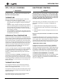
REFRIGERATORS
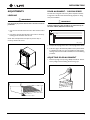
ADJUSTMENTS
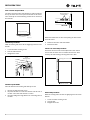
DOOR ALIGNMENT - 2100/2200 SERIES
LEVELING
The unit’s door is aligned at the factory before shipment. However,
its alignment could have been disturbed during shipment or during
door panel installation.
IMPORTANT
IMPORTANT
It is extremely important that the unit is level for maximum
production.
Properly aligned, the door should be 1/8" below the top of
the unit’s cabinet, NOT flush with the top.
1. Use a level to check the unit from front to back and from side to
side.
2. If the unit is not level, adjust the feet on the corners as necessary.
Rotating the feet clockwise raises the unit.
1/8"
Check after each adjustment and repeat the previous steps as
necessary until the unit is level.
ULIN_0295_A
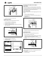
1. Compare the top edge of the door to the top edge of the cabinet.
2. If the door edge is 1/8" below and parallel to the top of the cabinet,
it is adjusted correctly. If it is not, note whether the side opposite
the hinge needs to be moved UP or DOWN, and use the following
procedure.
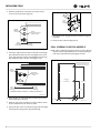
ADJUSTING DOOR ALIGNMENT
1. Remove top hinge screw pin using a Phillips screwdriver. Remove
door by tilting forward and lifting off bottom hinge pin.
1
Turn Foot to Adjust
1
REFRIGERATORS
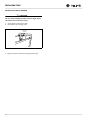
2. With door upside-down, loosen but do not remove the two
screws on the door’s bottom hinge plate.
Door
Closer
Inserts
Slotted
Mounting
Holes
Notch
(must face toward
center of door)
Boss
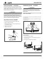
7. Reinstall the closers, lining up the bosses with holes in hinge and
hinge plate.
8. Mount the door, install top hinge pivot pin.
Raise
Outside
Door Edge
Lower
Outside
Door Edge
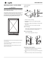
FULL OVERLAY 2100/2200 MODELS
3. If the top far edge of the door needs to move UP, move the hinge
plate toward the outside of the door and retighten screws. If the
top far edge of the door needs to move DOWN, move the hinge
plate toward the inside of the door and retighten screws.
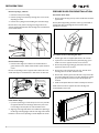
NOTE: If door is adjusted correctly, but panel is not square with the
adjacent cabinets, slight adjustments can be made by drilling the
holes in the vinyl-coated steel panel slightly oversized.
Drill 5/32"x 3/8" Deep for use
with #10 x 5/8" Wood Screw
and Nylon Spacer –6 Places
Slotted
Mounting
Holes
Angled Edge
Towards Center
of Door
Rear View
of
Wood Panel
Raise
Outside
Door Edge
Lower
Outside
Door Edge
27"r1/4"
14-5/16"r1/4"
2100/2200 Models with Glass or Stainless Steel Doors
1"r1/8"
ULIN_0311_A
4. Mount the door to recheck alignment and repeat steps 2 and 3 if
further adjustment is necessary.
5. When top edge of door is parallel to top edge of cabinet, remove
the door and ensure the two screws are secure.
6. Remove the door closers from the bottom hinge, clean thoroughly
and lubricate the mating surfaces with petroleum jelly.
2
1"r1/32"
1"r1/32"
ULIN_0310_A
REFRIGERATORS
REVERSING DOORS - 2100/2200 SERIES
To reverse the door:
Remove door:
IMPORTANT
Stainless Steel units must be ordered right or left hand hinge.
They are NOT field reversable.
All U-Line black or white units may have the hinge mounted on the left
or right side of the cabinet. Stainless steel unit doors cannot be
reversed. The doors are easily reversed by moving the hinge hardware
to the opposite side. The top right hinge will be used on the bottom
left and the bottom right hinge will be used on the top left.
3
1
2
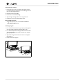
1. Hold door to keep it fram falling.
2. Remove hinge screw pin (1) from top hinge using a phillips
screwdriver.
3. Remove door by tilting forward and lifting door off bottom hinge
closer inserts.
4. Reinstall hinge screw pin (1) into top hinge using a phillips
Remove hole plugs.
Remove plastic screw plugs (three each, top and bottom) (3)
from new hinge location. Save for reinstallation later.
Remove existing top hinge.
Remove existing top hinge (three screws) (2).
ULIN_0015_A
The hinge hardware will be removed and reinstalled on the opposite
side of the cabinet.
The top hinge hardware will be reinstalled on the bottom of the
opposite side of the cabinet.
The bottom hinge hardware will be reinstalled on the top of the
opposite side of the babinet
4
ULI
4
Reinstall hinge to bottom opposite.
1. Install the hinge just removed from the top to the BOTTOM
opposite side of the cabinet (three screws) (2).
2. Remove the two door closer inserts (4) from the existing bottom
hinge.
3. Install door closer insertys as shown on the new bottom hinge
3
REFRIGERATORS
Remove existing bottom hinge.
Remove the existing bottom hinge (three screws) (2).
Reinstall hinge to top opposite.
Install the hinge just removed from the bottom to the TOP
opposite side of the cabinet (three screws) (2).
Reinstall hole plugs.
Install plastic screw plugs (three each, top and bottom) (3) into
holes where hinge hardware was removed.
NOTCH
5
Black or White Doors
Glass or Stainless Steel Doors
Prepare door for reinstallation.
1. Remove plastic hole plug from top of door handle and reinstall on
opposite side.
2. With bottom of door facing up remove pivot plate (5) (two
screws).
3. Flip over and install pivot plate on opposite side of door. Ensure
notch in plate faces center.
Install Door.
1. Hold door upright and tilted toward you.
2. Lift door on to bottom hinge closer inserts.
3. Move door toward the unit into position.
4. Hold door to keep it from falling.
5. Reinstall hinge screw pin (1) into top hinge using a phillips
screwdriver.
Align and adjust the door as needed.
4
REFRIGERATORS
Drawer Alignment
ADJUSTING DRAWER ALIGNMENT
CHECKING DRAWER ALIGNMENT
WARNING
The unit’s drawers are aligned at the factory before shipment.
However, their alignment could have been disturved during shipment
or during overlay panel installation.
SHOCK HAZARD - The unit must be unplugged from
the wall outlet during drawer removal, adjustment
and re-installation
DRAWER REMOVAL
Aligned
Front-to-Back
1.
2.
3.
Aligned
Side-to-Side
Confirm that the unit is unplugged from wall outlet.
Unplug the drawer’s connection wiring (top drawer only).
Remove the mounting screws.
Mounting
Screw
Aligned
Top-to-Bottom
ULIN_0001a_A
Check each drawer to confirm that it is aligned:
•
•
•
Side-to-Side - When viewed from the top, the drawer front
should be square with the sides of the cabinet.
Front to Back - When viewed from the side, the drawer front
should be straight with the cabinet’s sides, not cocked forward
or back.
Top-to-Bottom - When viewed from the front, the drawer
should be level horizontally.
4.
Pull the drawer completely out of the unit.
CAUTION
Use care when handling the drawer. Drawer edges, drawer
rail and the unit’s slide may be sharp.
IMPORTANT
Drawer adjustments are made by moving the slide that carries the drawer’s rail. Minor adjustments may be made by
loosening one of the slide’s mounting screws, adjusting the
slide and retightening the screw. Severe adjustments may be
made by removing the slides’ mounting screws, drilling new
mounting holes and remounting the slide.
1
REFRIGERATORS
SIDE-TO-SIDE ADJUSTMENT
The drawer will need a side-to-side adjustment if, when viewed from
the top, the drawer front is not square with the sides of the cabinet.
This is caused by one of the slides being mounted too far forward on
the unit’s liner.
Mark and Drill New
Mounting Holes
Level the Slide
Not Aligned Side-to-Side
Top View of Unit
ULIN_0001c_A
MINOR ADJUSTMENT
NOTE: The mounting holes on the slide are slightly larger than the screws’
diameter.
1.
2.
3.
Loosen the slide’s mounting screws.
Push the slide backward.
Retighten the screws.
NOTE: Front location holes are shown. Corresponding rear holes will also
need to be marked.
4.
5.
Drill all the new holes with a #30 drill bit.
Remount the slide.
FRONT-TO-BACK ADJUSTMENT
The drawer will need a front-to-back adjustment if, when viewed
from the side, the drawer front is cocked forward or back. This is
caused by the slide mountings not being level front to back.
Loosen
Mounting Screws
Not Aligned Front-to-Back
Push Slide
Backward
Side View of Unit
SEVERE ADJUSTMENT
Note: The slides have extra mounting holes that may be used.
1.
2.
3.
Remove the slide’s mounting screws.
Reposition the slide so it is the same distance from the front of
the liner as the other slide. Measure to confirm.
Mark new drilling holes using different sets of mounting holes on
the slide.
MINOR ADJUSTMENT
NOTE: The mounting holes on the slide are slightly larger than the screws’
diameter.
1.
2.
3.
2
Loosen one slide’s mounting screws.
Level the slide.
Retighten the screws.
REFRIGERATORS
Screws Should
Be Loose
TOP-TO-BOTTOM (AND LEFT-TO-RIGHT)
ADJUSTMENT
The drawer will need a top-to-bottom adjustment if, when viewed
from the front, the drawer is not level horizontally. Viewed from the
top, one side will protrude. This is caused by one of the slides being
mounted higher than the other slide on the unit’s liner.
MINOR ADJUSTMENT
NOTE: The mounting holes on the slide are slightly larger than the screws’
diameter.
Level the Slide
1.
2.
3.
4.
Loosen one slide’s mounting screws.
Push the slide upward or downward to match the position of
the other slide
Retighten the screws.
Repeat the procedure for the other slide.
Loosen
Mounting Screws
SEVERE ADJUSTMENT
NOTE: The slides have extra mounting holes that may be used.
1.
2.
3.
4.
Loosen one slide’s rear mounting screws.
Remove the slide’s front mounting screws.
Reposition the slide so it is level.
Mark new front drilling holes using a different set of mounting
holes on the slide.
Push Slide
Upward or
Downward
Mark and Drill New
Mounting Holes
4.
Repeat the procedure with the other slide if necessary.
SEVERE ADJUSTMENT
NOTE: The slides have extra mounting holes that may be used.
Level the Slide
ULIN_0001h_A
1.
2.
3.
5.
6.
7.
Drill the new holes with a #30 drill bit.
Remount the slide.
Repeat the procedure for the other slide.
Remove one slide’s mounting screws.
Reposition the slide so it is the same distance from the bottom
of the liner as the other slide. Measure to confirm.
Mark new drilling holes using different sets of mounting holes on
the slide.
Mark and Drill New
Mounting Holes
Not Aligned
Top-to-Bottom
Not Aligned Left-to-Right
Front View of Unit
Top View of Unit
Push Slide
Upward or
Downward
NOTE: Front location holes are shown. Corresponding rear holes will also
need to be marked.
4. Drill all the new holes with a #30 drill bit.
5. Remount the slide.
3
REFRIGERATORS
RE-INSTALLATION OF DRAWER
CAUTION
Use care when handling the drawer. Drawer edges, drawer
rail and the unit’s slide may be sharp.
1.
2.
Set the drawer’s rails onto the slides.
Re-install the rails’ mounting screws
Mounting
Screw
3.
4
Plug in the drawer’s connection wiring (top drawer only).
REFRIGERATORS
DOOR ALIGNMENT - 1100 SERIES
The unit’s door is aligned at the factory before shipment. However,
its alignment could have been disturbed during shipment or during
installation. Align and adjust the door if it is not level, or is not sealing
properly. If the door is not sealed the unit may not cool properly, or
excessive frost may form in the interior.
IMPORTANT
Properly aligned, the door’s gasket should be firmly in contact with the cabinet all the way around the door (no gaps).
Carefully examine the door’s gasket to assure that it is
firmly in contact with the cabinet. Also make sure the door
gasket is not pinched on the hinge side of the door.
ADJUSTING DOOR ALIGNMENT
REVERSING DOORS - 1100 SERIES
IMPORTANT
Models with black and white doors are field-reversible.
Stainless steel models with glass doors without locks are
field-reversible.
Stainless steel models without glass doors must be ordered
right- or left-hand hinged.
The Hinge hardware will be removed and reinstalled on the opposite
side of the cabinet.
The hinge plate is flipped over when it is reinstalled on the opposite
side of the cabinet.
1. Loosen (do not remove) top and bottom hinge screws.
2. Align door squarely with cabinet.
3. Make sure gasket is firmly in contact with cabinet all the way
around the door (no gaps).
Plastic
Plug Hole
Plastic
Plug Hole
Right Side
Door Swing
Left Side
Door Swing
4. Tighten bottom hinge screws.
5. Tighten top hinge screws.
Remove the grille
1. Remove control knob if equipped
2. Remove the two screws (1). Some models may have only one
screw in the center.
3. Remove grille (2) and grille cap (3) if equipped.
3
2
1
2
1
1
REFRIGERATORS
Remove top hinge, and door:
PREPARE DOOR FOR REINSTALLATION
1. Hold door to keep it from falling.
For black or white doors:
2. Remove top hinge from cabinet by removing three or four screws,
depending on model.
1. Remove plastic hole plug from top of door handle and reinstall on
opposite side.
3. Remove door by tilting forward and lifting door off bottom hinge.
Remove plastic hinge bushing on bottom of door (1) and reinstall on
opposite side. Clean out bushing hole in door bottom with a
screwdriver if necessary.
Remove three or four plastic screw plugs from hinge holes on the
opposite side. Reinstall into holes where the hinge was removed. Ensure
not to scratch cabinet.
1
For stainless steel models with glass doors:
1. Stainless glass doors are flipped upside down to be reversed.
Remove bottom hinge
1. Remove bottom hinge from cabinet. Some models will have a
gusset with two screws. Other models will have a plate with three
screws.
Remove corresponding screws on opposite side of cabinet. On some
models there may be a nut behind one or both screws on either side.
2. Lay the door on it’s side. Remove the plastic hole plug (1) and
install in the corner opposite of where it was removed.
3. Remove the plastic hinge bushing (2) and install in the corner
opposite of where it was removed.
4. Remove the U-Line nameplate (3) from door. This will reveal
mounting holes for the door actuator bracket.
5. Remove door actuator (4) from door. Be sure to only remove the
two screws holding the actuator to the door. Reinstall the actuator
(4) on the opposite end of the door where the nameplate was
removed.
6. Install new nameplate where the actuator assembly was removed.
Install screws into holes on opposite side, where the hinge was
removed. Replace nuts if used.
Install bottom hinge:
1. If you have a plate hinge, reorient the pivot screw so it protrudes
the opposite direction form the hinge. Remove the pivot screw
from the hinge. Turn the plate over and reinstall the screw.
3
4
2. Align hinge outer edge with cabinet. For models with a plate hinge,
the flat edge of the hinge alignes with the outer edge of the cabinet.
Install two or three screws, depending on model. Replace nuts if used.
2
2
1
REFRIGERATORS
Install top hinge, and door:
1. Reorient the pivot screw so it protudes the opposite direction
from the hinge. Remove the pivot screw from the hinge. Turn the
plate over and reingstall the screw.
2. Hold door to keep it from falling.
3. Lift the door on to the bottom hinge.
4. Align flat edge of the hinge with the outer edge of the unit.
5. Install three or frour screws, depending on model.
Align and adjust the door:
Align and adjust the door, see DOOR ALIGNMENT
AND ADJUSTMENT above.
Installing the grille:
1. For 1115 and 29 models make sure grille cap (3) is behind grille in
slots (2) provided in grille before attaching grille to unit.
2. For 1175 models place the hook-hinge located on the rear bottom
side of the grille (2) onto the front lip of the unit base. Swing the
grille up into position.
3. Align cabinet and grille holes and secure, but do not overtighten
grille screws (1).
4. Install control knob if equipped.
3
2
1
2
1
3