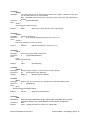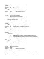
1
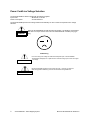
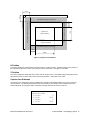
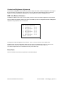
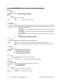
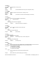
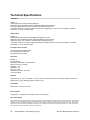
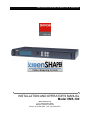
INSTALLATION AND OPERATOR’S MANUAL Manual #26-0208100-00 / Revision E INSTALLATION AND OPERATOR’S MANUAL Model VMS-100 Barco Folsom, LLC 11101 Trade Center Drive Rancho Cordova CA 95670 Phone: (916) 859-2500 • Fax: (916) 859-2515 RECORD OF CHANGES REV # A B DATE 03/18/2003 05/21/2003 ECO # 1001 1059 C D 07/03/2003 10/10/2003 1066 1155 E 8/03/04 1301 DESCRIPTION Release to production. Addition of the storage for Keystone and User-defined warp maps Addition of the Rotation Mode Modify the Capture and Display Menu interface Expanded to cover new features in Maincode release 2.04 Approved By April Luong April Luong April Luong April Luong Jim Rodeo Manual # 26-0208100-00 Operators Safety Summary The general safety information in this summary is for operating personnel. Do Not Remove Covers or Panels There are no user-serviceable parts within the unit. Removal of the top cover will expose dangerous voltages. To avoid personal injury, do not remove the top cover. Do not operate the unit without the cover installed. Power Source This product is intended to operate from a power source that will not apply more than 230 volts rms between the supply conductors or between both supply conductor and ground. A protective ground connection by way of grounding conductor in the power cord is essential for safe operation. Grounding the Product This product is grounded through the grounding conductor of the power cord. To avoid electrical shock, plug the power cord into a properly wired receptacle before connecting to the product input or output terminals. A protective-ground connection by way of the grounding conductor in the power cord is essential for safe operation. Use the Proper Power Cord Use only the power cord and connector specified for your product. Use only a power cord that is in good condition. Refer cord and connector changes to qualified service personnel. Use the Proper Fuse To avoid fire hazard, use only the fuse having identical type, voltage rating, and current rating characteristics. Refer fuse replacement to qualified service personnel. Do Not Operate in Explosive Atmospheres To avoid explosion, do not operate this product in an explosive atmosphere. Terms In This Manual and Equipment Marking VORSICHT WARNING NOTE Highlights an operating procedure, practice, condition, statement, etc., which, if not strictly observed, could result in injury to or death of personnel. Highlights an essential operating procedure, condition or statement. CAUTION The exclamation point within an equilateral triangle is intended to alert the user to the presence of important operating and maintenance (servicing) instructions in the literature accompanying the appliance. AVERTISSEMENT! Le point d´exclamation dans un triangle equilatéral signale à alerter l´utilisateur qu´il y a des instructions d´operation et d´entretien tres importantes dans la litérature qui accompagne l´appareil ein Ausrufungszeichen innerhalb eines gleichwinkeligen Dreiecks dient dazu, den Benutzer auf wichtige Bedienungs-und Wartungsanweisungen in der Dem Great beiliegenden Literatur aufmerksam zu machen. ScreenSHAPER Quick Start Guide 1. Identify the following items supplied with the ScreenSHAPER: a. ScreenSHAPER system unit b. ScreenSHAPER AC power cable c. DVI to HD-15 interface adapters (2 supplied) d. RS-232 serial cable, 6 ft. P/N 14-9760048-00 e. CDROM containing Setup and Calibration software and manual 2. Set up an external computer (not supplied) to be used to configure and calibrate the ScreenSHAPER. This computer requires the following: a. Windows 95, 98, 2000, NT or XP operating system b. CDROM drive c. 20 Megabytes free hard disk space d. One RS-232 serial port configured as COM1, COM2, COM3, or COM4 e. Video card capable of 1280x1024 output resolution f. Video monitor capable of 1280x1024 display resolution g. Keyboard h. Mouse 3. Equipment Setup a. Connect the image source to the VIDEO IN connector on the rear of the ScreenSHAPER. Use the supplied DVI to HD-15 adapter (p/n 15-000002-00 ) as required. b. Connect the output device to the VIDEO OUT connector on the rear of the ScreenSHAPER. Use the supplied DVI to HD-15 adapter (p/n 15-0000002-00 ) as required. c. Connect the supplied serial cable to the RS-232 connector on the rear of the ScreenSHAPER. d. Connect the other end of the supplied serial cable to the RS-232 serial port of the external computer. e. Power on the external computer. When it has finished booting, install the setup and calibration software from the CDROM. Note that this software is not configured for AUTORUN so it will be necessary to display the contents of the CDROM using Windows Explorer and double-click on the installation. Follow the on-screen instructions to complete the installation. f. Power on the external output display device (projector or monitor). 4. Power on the ScreenSHAPER and wait for it to complete its initialization sequence. The video source should be displayed on the output device. 5. Start the Setup and Calibration program by clicking on the Start->Folsom Research->Calibration Software. 6. Follow the instructions in the Setup and Calibration Manual to complete the setup, calibration, and configuration of the ScreenSHAPER. This is a quick reference guide. For detailed information on the ScreenSHAPER, please refer to the Installation and Operating Manual supplied with your unit. Barco Folsom, LLC. • 11101-A Trade Center Drive, Rancho Cordova CA 95670 • (916) 859-2500 • www.folsom.com Manual # 26-0208100-00 / Revision E ScreenSHAPER – Video Mapping System i Table of Contents SCREENSHAPER ______________________________________________________________________________________I QUICK START GUIDE__________________________________________________________________________________I INTRODUCTION______________________________________________________________________________________ 2 ABOUT THE SCREENSHAPER _____________________________________________________________________________ 2 TYPICAL OPERATION ____________________________________________________________________________________ 2 FEATURES _____________________________________________________________________________________________ 2 INSTALLATION ______________________________________________________________________________________ 4 REAR PANEL CONNECTORS _______________________________________________________________________________ RACK-MOUNT INSTALLATION _____________________________________________________________________________ RS-232 REMOTE CONTROL CONNECTION ____________________________________________________________________ VIDEO IN AND VIDEO OUT CONNECTORS ____________________________________________________________________ POWER CORD/LINE VOLTAGE SELECTION ___________________________________________________________________ 4 4 4 5 6 OPERATION ________________________________________________________________________________________ 10 FRONT PANEL CONTROLS _______________________________________________________________________________ POWER UP INITIALIZATION ______________________________________________________________________________ SYSTEM STATUS DISPLAY ________________________________________________________________________________ MENU CONTROL _______________________________________________________________________________________ INPUT SETUP MENU ____________________________________________________________________________________ SAVE SETTINGS ________________________________________________________________________________________ AUTO CONFIG _________________________________________________________________________________________ SYNC SELECT __________________________________________________________________________________________ H TOTAL _____________________________________________________________________________________________ H POSITION ___________________________________________________________________________________________ V POSITION ___________________________________________________________________________________________ CAPTURE AREA SUBMENU ________________________________________________________________________________ H Start _______________________________________________________________________________________________ H Size _______________________________________________________________________________________________ V Start _______________________________________________________________________________________________ V Size _______________________________________________________________________________________________ PHASE OFFSET _________________________________________________________________________________________ CONTRAST AND BRIGHTNESS ADJUSTMENTS __________________________________________________________________ RGB COLOR BALANCE SUBMENU __________________________________________________________________________ RESET COLOR__________________________________________________________________________________________ OUTPUT SETUP MENU __________________________________________________________________________________ SAVE SETTINGS ________________________________________________________________________________________ WARPING _____________________________________________________________________________________________ WARP MAP INDEX ______________________________________________________________________________________ V KEYSTONE __________________________________________________________________________________________ H KEYSTONE __________________________________________________________________________________________ ROTATION ____________________________________________________________________________________________ FLIP _________________________________________________________________________________________________ FREEZE _______________________________________________________________________________________________ FORMAT ______________________________________________________________________________________________ FRAME RATE __________________________________________________________________________________________ SYNC SELECT __________________________________________________________________________________________ DISPLAY AREA SUBMENU ________________________________________________________________________________ ii ScreenSHAPER – Video Mapping System 10 10 11 11 12 12 12 12 12 13 13 13 14 14 14 14 14 15 15 15 16 16 16 16 16 17 17 17 17 17 17 17 18 Manual # 26-0208100-00 / Revision E Left Edge_____________________________________________________________________________________________ Right Edge ___________________________________________________________________________________________ Top Edge_____________________________________________________________________________________________ Bottom Edge __________________________________________________________________________________________ GAMMA CORRECTION SUBMENU ___________________________________________________________________________ R Gamma ____________________________________________________________________________________________ G Gamma ____________________________________________________________________________________________ B Gamma ____________________________________________________________________________________________ TIMING LOCK __________________________________________________________________________________________ RASTER BOX __________________________________________________________________________________________ TEST PATTERN SETUP MENU _____________________________________________________________________________ PATTERN _____________________________________________________________________________________________ TEST PATTERN GRID ____________________________________________________________________________________ TEST PATTERN BOX _____________________________________________________________________________________ EDGE FEATHER SUBMENU ________________________________________________________________________________ Left Feather___________________________________________________________________________________________ Left Width____________________________________________________________________________________________ Left Gamma __________________________________________________________________________________________ Right Feather__________________________________________________________________________________________ Right Width___________________________________________________________________________________________ Right Gamma _________________________________________________________________________________________ Curve________________________________________________________________________________________________ SYSTEM SETUP MENU ___________________________________________________________________________________ SAVE SETTINGS ________________________________________________________________________________________ SERIAL PORT SUBMENU __________________________________________________________________________________ Echo ________________________________________________________________________________________________ Baud Rate ____________________________________________________________________________________________ Data Bits _____________________________________________________________________________________________ Stop Bits _____________________________________________________________________________________________ Parity ________________________________________________________________________________________________ Handshaking __________________________________________________________________________________________ Reset RS-232 _________________________________________________________________________________________ FIRMWARE VERSIONS MENU ______________________________________________________________________________ TECH SUPPORT MENU ___________________________________________________________________________________ DIAGNOSTICS MENU ____________________________________________________________________________________ Front Panel Test _______________________________________________________________________________________ I2C Bus Test __________________________________________________________________________________________ VFD BRIGHTNESS ______________________________________________________________________________________ OPERATION MODE ______________________________________________________________________________________ SYSTEM RESET _________________________________________________________________________________________ 18 18 18 18 19 19 19 19 19 19 20 20 20 20 21 21 21 21 21 21 21 21 22 22 22 22 22 22 23 23 23 23 23 23 23 24 24 24 24 24 REMOTE COMMANDS _______________________________________________________________________________ 26 SCREENSHAPER COMMAND LIST/DESCRIPTION _____________________________________________________ 28 OVERVIEW ___________________________________________________________________________________________ HARDWARE REQUIREMENTS _____________________________________________________________________________ SOFTWARE REQUIREMENTS ______________________________________________________________________________ CONNECTING TO BARCO FOLSOM _________________________________________________________________________ DOWNLOADING NECESSARY FILES ________________________________________________________________________ INSTALLING SCREENSHAPER SOFTWARE FILES AND FLASH FILE LOADER ________________________________________ STARTING THE FLASH FILE LOADER UTILITY __________________________________________________________________ PREPARING TO UPGRADE THE SCREENSHAPER UNIT ___________________________________________________________ UPLOADING FILES TO THE SCREENSHAPER UNIT ______________________________________________________________ 39 39 39 39 39 39 40 40 40 BARCO FOLSOM INFORMATION _____________________________________________________________________ 42 BARCO FOLSOM, LLC WARRANTY ________________________________________________________________________ 42 Manual # 26-0208100-00 / Revision E ScreenSHAPER – Video Mapping System iii RETURN MATERIAL AUTHORIZATION (RMA) _______________________________________________________________ 42 BARCO FOLSOM CONTACT INFORMATION___________________________________________________________________ 42 TECHNICAL SPECIFICATIONS _______________________________________________________________________ 44 iv ScreenSHAPER – Video Mapping System Manual # 26-0208100-00 / Revision E 1 CHAPTER ONE Introduction What you will find in this chapter… About The ScreenSHAPER Typical Operation Features Model VMS-100 Manual # 26-0208100-00 / Revision E ScreenSHAPER – Video Mapping System 1 Introduction About the ScreenSHAPER The ScreenSHAPER accepts analog RGB video or digital DVI video from one video source and re-maps the image for display on a non-flat or off-axis surface using a projector. The output video is generated in analog and DVI format. An external computer is required to generate the “warp map” used to correct for the non-flat or off-axis surface. Typical Operation The ScreenSHAPER can be used whenever it is necessary to project images from a projector to a non-flat or off-axis surface. Typical applications include advertising displays, flight simulators, keystone correction, and home theater. Features • Accepts RGB and DVI video input with resolutions up to 1280x1024, non-interlaced • Automatically locks to the input video and processes it in real-time • Processes the entire input image or a user-defined “area of interest” • Supports independent X,Y scaling for aspect ratio corrections • User-selectable output formats: VGA (640x480), SVGA (800x600), XGA (1024x768), SXGA (1280x1024), 1280x720, 1280x768, 1280x960 • Supports analog RGB and digital DVI concurrent video output • Simple, intuitive front panel controls support quick setup • RS-232 serial interface for remote control of all functions with Graphical User Interface software • Rugged 19” rack-mount chassis • Non-volatile storage for configuration data • Built-in test pattern generator • Backed by a full 3-year parts and labor warranty 2 ScreenSHAPER – Video Mapping System Manual # 26-0208100-00 / Revision E 2 CHAPTER TWO Installation What you will find in this chapter… Rear Panel Connectors Rack-Mount Installation Remote Control Connection Video Input & Output Connections Power Cord/Line Voltage Selection Model VMS-100 Manual # 26-0208100-00 / Revision E ScreenSHAPER – Video Mapping System 3 Installation Rear Panel Connectors Figure 2-1: ScreenSHAPER Rear Panel Rack-Mount Installation ScreenSHAPER units are designed to be rack mounted and are supplied with front rack-mount hardware. Rear rackmount brackets are available as a kit and are recommended for use when units are mounted in transit cases. When rack mounting the unit, remember that the maximum ambient operating temperature for the unit is 40 degrees C. Leave at least one inch of space front and rear to make sure that the airflow through the fan and vent holes is not restricted. When installing equipment into a rack, distribute the units evenly to prevent hazardous conditions that may be created by uneven weight distribution. Connect the unit only to a properly rated supply circuit. Reliable grounding (earthing) of rack-mounted equipment should be maintained. RS-232 Remote Control Connection The RS-232 serial port is used to connect the ScreenSHAPER to an external computer to support setup and calibration of the ScreenSHAPER. The serial port is configured as a DCE device which allows a straight-through serial cable to be used to connect the ScreenSHAPER to the PC. The cable connecting to the ScreenSHAPER should have a DB-9 male connector. Pinouts for the remote port are shown below. The cable supplied with the unit, p/n 14-9760048-00, or equivalent RS-232 serial cable should be used to connect the ScreenSHAPER to the external computer. DCE DB-9 I/O 4 RS-232 Signal Name ScreenSHAPER Signal Description CD 1 O Carrier Detect Carrier Detect from Remote Control PC RXD 2 O Received Data Data Sent to Remote Control PC TXD 3 I Transmitted Data Data From Remote Control PC DTR 4 I Data Terminal Ready Data Terminal Ready from Remote Control PC GND 5 x Signal Ground DSR 6 O Data Set Ready Data Set Ready Output to Remote Control PC RTS 7 I Request To Send from Remote Control PC CTS 8 O Clear To Send Clear To Send Output to Remote Control PC RI 9 O Ring Indicator Unused Request To Send ScreenSHAPER – Video Mapping System Signal Ground Manual # 26-0208100-00 / Revision E Video In and Video Out Connectors Two DVI-I female connectors are located on the rear panel of the ScreenSHAPER. One is used for VIDEO IN and one is used for VIDEO OUT. Adapters are supplied to connect HD-15 cables to the DVI-I connector for analog devices. Pin Function Pin Function 1 T.M.D.S. Data2- 13 T.M.D.S. Data3+ 2 T.M.D.S. Data2+ 14 +5V Power 3 T.M.D.S. Data2/4 Shield 15 ground (for +5V) 4 T.M.D.S. Data4- 16 Hot Plug Detect 5 T.M.D.S. Data4+ 17 T.M.D.S. Data0- 6 DDC Clock 18 T.M.D.S. Data0+ 7 DDC Data 19 T.M.D.S. Data0/5 Shield 8 Analog Vertical Sync 20 T.M.D.S. Data5- 9 T.M.D.S. Data1- 21 T.M.D.S. Data5+ 10 T.M.D.S. Data1+ 22 T.M.D.S. Clock Shield 11 T.M.D.S Data1/3 Shield 12 T.M.D.S. Data3- 23 T.M.D.S. Clock+ 24 T.M.D.S. Clock- MicroCross Pins Pin Function C1 Analog Red Video C2 Analog Green Video C3 Analog Blue Video C4 Analog Horizontal Sync C5 Analog Common Ground Return Legend DDC = Display Data Channel T.M.D.S. = Transition Minimized Differential Signal Manual # 26-0208100-00 / Revision E ScreenSHAPER – Video Mapping System 5 Power Cord/Line Voltage Selection The ScreenSHAPER is rated to operate with the following supplies: Input Power: 98-264VAC, 47-63 Hz Power Consumption: 45 watts maximum The ScreenSHAPER performs line voltage selection automatically. No user controls are required for line voltage selection. WARNING When the ScreenSHAPER is used with 230-volt supplies, a UL listed line cord rated for 250 volts at 15 amps must be used. This cord will be fitted with a tandem prong-type plug. Tandem Plug La choix de la ligne de voltage se realize automatiquement par Ie ScreenSHAPER Transformateur Graphique On n’apas besoin du controller usager pour la choix de la ligne de voltage. AVERTISSEMENT Das ScreenSHAPER -Gerät mu beim Anschlu an 240V ~ mit einer vom VDE auf 250V/10A geprüften Netzleitung mit einem Schukostecker ausgestattet sein. AVERTISSEMENT 6 ScreenSHAPER – Video Mapping System Manual # 26-0208100-00 / Revision E Connect ScreenSHAPER to AC power using the power cord supplied with the unit. Locate the power switch on the power entry module at the rear of the unit and turn the power on. While the main board is initializing, “please wait” will be displayed and the front panel keys will be turned on and off. When initialization is complete, the Status Display screen will be displayed. VORSICHT ein Ausrufungszeichen innerhalb eines gleichwinkeligen Dreiecks dient dazu, den Benutzer auf wichtige Bedienungs-und Wartungsanweisungen in der Dem Great beiliegenden Literatur aufmerksam zu machen. WARNING The rear panel ON/OFF switch does not disconnect the unit from input AC power. To facilitate disconnection of AC power, the power cord must be connected to an accessible outlet near the unit. Building Branch Circuit Protection: For 115 V use 20 A, for 230 V use 8 A. WARNING When the ScreenSHAPER is used in the 230-volt mode, a UL listed line cord rated for 250 volts at 15 amps must be used and must conform to IEC-227 and IEC-245 standards. This cord will be fitted with a tandem prong-type plug. Manual # 26-0208100-00 / Revision E ScreenSHAPER – Video Mapping System 7 3 CHAPTER THREE Operation What you will find in this chapter… Front Panel Controls System Status Display Menu Control Input Video Setup Menu Output Video Setup Menu Test Pattern Menu System Setup Menu Model VMS-100 Manual # 26-0208100-00 / Revision E ScreenSHAPER – Video Mapping System 9 Operation The ScreenSHAPER must be set up and calibrated using an external computer (not supplied) and the ScreenSHAPER Calibration Software (provided). The front panel can be used to make minor configuration adjustments to the input and output settings. The front panel controls are described in detail in this section; the serial port commands are described in the next section. Front Panel Controls SEL IN ADJ TEST PAT ESC OUT ADJ SYS SETUP VFD Display Figure 3-1 ScreenSHAPER Front Panel The Front Panel controls include a vacuum fluorescent display (VFD), an adjustment knob, and six illuminated push buttons. The operation of each menu displayed on the VFD is described in detail in the following sections of this document. Power Up Initialization Locate the power switch on the rear panel and turn the ScreenSHAPER ON. While the system is initializing, the following message will be displayed on the VFD display: ScreenSHAPER VERSION 2.04 INITIALIZING PLEASE WAIT... The version number displayed is the system software version number. The software version number will change as software upgrades are released. 10 ScreenSHAPER – Video Mapping System Manual # 26-0208100-00 / Revision E System Status Display The System Status Display is displayed whenever a configuration menu is not being displayed. This four-line display contains “SYSTEM STATUS” on the first line indicating that this is the system status display screen. The second line contains the video input format and the input type (ANALOG or DIGITAL). The third line contains the output resolution and frame rate. Depending on the mode of operation, the last line contains the current operation status. The status information could be the Warping Mode or the Rotation Setting. “TEST” is displayed if a test pattern is being generated by the internal test pattern generator. Warp Mode: SYSTEM STATUS INPUT: SXGA ANALOG OUTPUT: SXGA 60HZ WARP OFF LIVE Rotation Mode: SYSTEM STATUS INPUT: SXGA OUTPUT: SXGA ROTATION 0 ANALOG 60HZ LIVE Menu Control The adjustment knob as well as the SEL and ESC keys is used to navigate through a series of menus displayed on the VFD display. The menus are used to enter setup parameters. Once setup parameters are entered, they are stored in non-volatile memory for future use using the system save menu item. Pressing one of the four hot keys will call up the corresponding menu on the VFD. The user can scroll through the menu items by turning the ADJUST control knob. A pointer (>) at the left of a menu item indicates the current position of the scroll bar. When the desired menu item is reached, the user presses the SEL key to select that menu item. The sub-menu pointer (>>) at the right of a menu item indicates that a sub-menu will be displayed if that menu item is selected. The pointer at the left hand side of the display changes to a pound sign (#) indicating that a parameter is selected. After a parameter has been selected, the user can modify the associated parameter values by turning the ADJUST control knob. The operator can accept the changes with SEL or press ESC to exit the current menu item without modifying current settings. In this section, the Factory Reset values are displayed in the menu diagram. Manual # 26-0208100-00 / Revision E ScreenSHAPER – Video Mapping System 11 Input Setup Menu This menu is used to configure the input. It is displayed when the IN ADJ key is pressed on the front panel. INPUT SETUP SAVE SETTINGS AUTO CONFIG SYNC SELECT H TOTAL HPOS (PIXELS) VPOS (LINES) CAPTURE AREA PHASE OFFSET BRIGHTNESS CONTRAST RGB COLOR BAL RESET CONFIG ^ ^ AUTO 1688 360 40 N/A 0 100.0% 100.0% >> ^ Save Settings This menu selection is used to save changes made in the Input Setup menu to non-volatile memory. If this menu item is not selected, changes will not be saved and the previous settings will be restored the next time the system is powered on. Auto Config This menu selection invokes the unit to perform an automatic sampling of the input video. The unit will attempt to capture the entire input based on the presence of data. The accuracy is higher on inputs that have a bright border around the entire image. This operation may take a minute or so. Do not perform an Auto Config on an entirely black image. Sync Select The sync format specifies the type of frame sync to be applied to the input video. The following settings are available: • AUTO - Automatically determine the output sync format • H/V Horizontal and Vertical Sync • COMP - Composite Sync • SOG - Sync on Green The default setting is AUTO. H Total This control sets the horizontal total number of pixel clock periods (active and blanking) during one horizontal line. The default setting is the number of pixels in the input video based on the input resolution. 12 ScreenSHAPER – Video Mapping System Manual # 26-0208100-00 / Revision E H Pos V Pos VSync Region Input Active Window V Size Capture Area (Area of Interest) V Start Horizontal Blanking Region (front porch) Horizontal Blanking Region (back porch) HSync Region Vertical Blanking Region (back porch) Vertical Blanking Region (front porch) H Start H Size Figure 3-2 Capture Area Definition H Position This control adjusts the horizontal start of the active video in number of pixels. The default setting is the position of the expected first pixel of the active video, based on the input resolution. See Figure 3-2 for detail. V Position This control adjusts the vertical start of the active video in number of lines. The default setting is the position of the expected first line of the active video, based on the input resolution. See Figure 3-2 for detail. Capture Area Submenu The following four configuration controls, available when operating in the Rotation Mode, are used to set an input “area of interest”. The default settings define a full-screen based on the resolution of the selected input source. These settings can be changed to define a particular rectangle within the full screen to zoom into. CAPTURE AREA H START H SIZE V START V SIZE Manual # 26-0208100-00 / Revision E 0 1280 0 1024 ScreenSHAPER – Video Mapping System 13 H Start H Start is used to set the horizontal start of the capture area in number of pixels. See Figure 3-2 for detail. The default setting is 0. H Size H Size is used to set the horizontal size of the capture area in number of pixels. See Figure 3-2 for detail. The default setting and the maximum setting is the number of active pixels of the input video, based on the input resolution. V Start V Start is used to set the vertical start of the capture area in number of lines. See Figure 3-2 for detail. The default setting is 0. V Size V Size is used to set the vertical size of the capture area in number of lines. See Figure 3-2 for detail. The default setting and the maximum setting is the number of active lines in the input video, based on the input resolution. Phase Offset Phase Offset is used to adjust the input sample clock phase. This control can be used to fine tune the image to eliminate artifacts due to input sampling clock phase errors. Changes can be made between –16 and 15. Since DVI video input requires no phase adjustment, this option is only available when using an analog video input. 14 ScreenSHAPER – Video Mapping System Manual # 26-0208100-00 / Revision E Contrast and Brightness Adjustments The Contrast and Brightness controls allow the operator to adjust the overall contrast and brightness of the image if the input is analog. The adjustment range is 75.0% to 125.0%. 100% is the default setting for both contrast and brightness. Contrast and brightness adjustments are only available when using an analog video input. RGB Color Balance Submenu The RGB Color Balance menu item is used to display a submenu where color balance adjustments are performed. This menu allows the operator to balance the colors on the RGB input source. Independent Contrast and Brightness adjustments are provided for each color channel. RGB COLOR BALANCE R CONTRAST 0.0% R BRIGHTNESS 0.0% G CONTRAST 0.0% G BRIGHTNESS 0.0% B CONTRAST 0.0% B BRIGHTNESS 0.0% RESET COLOR The adjustment range for Brightness and Contrast is -25.0% to +25.0% with 0.0% as the default value. The Reset Color menu item resets all the fields in this sub menu to the default value (0.0%). To reset the color balance controls, scroll to the Reset Color menu item and select the menu item with the SEL key. Color balance adjustments are not available when using a DVI video input. Reset Color This menu selection resets the input parameters to the default settings. Manual # 26-0208100-00 / Revision E ScreenSHAPER – Video Mapping System 15 Output Setup Menu The OUTPUT SETUP Menu allows the user to control output image configurations. Based on the Operation Mode, either the Warp Output Setup or the Rotation Output Setup menu is displayed when the OUT ADJ menu key is pressed on the front panel. Warp Mode: WARP OUTPUT SETUP SAVE SETTINGS ^ WARPING OFF WARP MAP INDEX 0 V KEYSTONE 0 H KEYSTONE 0 FREEZE DIS FORMAT SXGA 1280x1024 FRAME RATE 60Hz SYNC SELECT +H+V GAMMA CORRECTION >> TIMING LOCK DIS RASTER BOX OFF Rotation Mode: ROT OUTPUT SETUP SAVE SETTINGS ^ ROTATION 0 FLIP OFF FREEZE DIS FORMAT SXGA 1280x1024 FRAME RATE 60Hz SYNC SELECT +H+V DISPLAY AREA >> GAMMA CORRECTION >> TIMING LOCK DIS RASTER BOX OFF Save Settings This menu selection is used to save changes made in the Output Setup menu to non-volatile memory. If this menu item is not selected, changes will not be saved and the previous settings will be restored the next time the system is powered on. Warping The warping function can be set to OFF/ON/KEYSTONE*. The default is set to OFF. *The keystone function currently only supports these input-output settings: SVGA, XGA and SXGA inputs to SXGA output SVGA, XGA and SXGA inputs to XGA output SVGA and XGA inputs to SVGA output Warp Map Index If the warping function is set to ON, the image is processed according to the warp map indexed by this parameter. There are 9 warp maps that can be loaded and recalled by setting the Warp Map Index. The warp map has to be loaded prior to turning the warping function ON. It is required that the loaded warp map was generated for the current input-output resolution. V Keystone If the warping function is set to KEYSTONE, this menu selection set the vertical index of the keystone warp. The default is set to 0. 16 ScreenSHAPER – Video Mapping System Manual # 26-0208100-00 / Revision E H Keystone If the warping function is set to KEYSTONE, this menu selection set the vertical index of the keystone warp. The default is set to 0. Rotation There are four possible rotation angles that can be selected for the output: 0, 90, 180, and 270 degrees. Zero degree corresponds to an un-rotated image and is the default setting. Flip Flip causes the output image to be “mirrored”. Three settings are available: OFF, HORZ, and VERT. HORZ causes the output image to be mirrored left/right. VERT causes the output image to be mirrored top/bottom. The default setting is OFF. Freeze Freeze the display image. Format The format is the desired resolution of the output video. The following settings are available: • VGA - 640 x 480* • SVGA - 800 x 600 • XGA - 1024 x 768 • SXGA - 1280 x 1024 • 1280x720 • 1280x768 • 1280x960 *VGA output is not supported if the input format is 1280x1024. The default setting is SXGA. Frame Rate The frame rate specifies the number of times per second that the image is updated. The following settings are available: • 50Hz • 60Hz • 75Hz • 59.94Hz The default setting is 60Hz. Sync Select The sync format specifies the type of frame sync to be applied to the output video. The following settings are available: • SOG - Sync on Green • -C Composite Sync • +H+V - Pos Horizontal and Pos Vertical Sync • +H-V - Pos Horizontal and Neg Vertical Sync • -H+V - Neg Horizontal and Pos Vertical Sync • -H-V - Neg Horizontal and Neg Vertical Sync The default setting is +H+V. Manual # 26-0208100-00 / Revision E ScreenSHAPER – Video Mapping System 17 Display Area Submenu The following four configuration controls, available when operating in the Rotation Mode, are used to set an output display area. The default settings define a full-screen based on the selected output resolution. These settings can be changed to define a particular rectangle within the active output frame. DISPLAY AREA LEFT EDGE RIGHT EDGE TOP EDGE BOTTOM EDGE 0 1280 0 1024 Figure 3-3 Display Area Definition Left Edge Left Edge is used to set the output display area. This control adjusts the left edge by changing the width of the blank area on the left. See Figure 3-3 for detail. The default setting is 0. Right Edge Right Edge is used to set the output display area. This control adjusts the position of the right edge. See Figure 3-3 for detail. The default setting is 1280. Top Edge Top Edge is used to set the output display area. This control adjusts the top edge by changing the width of the blank area on the top. See Figure 3-3 for detail. The default setting is 0. Bottom Edge Bottom Edge is used to set the output display area. This control adjusts the position of the bottom edge. See Figure 3-3 for detail. The default setting is 1024. 18 ScreenSHAPER – Video Mapping System Manual # 26-0208100-00 / Revision E Gamma Correction Submenu Gamma Correction can be applied to the individual color components of the output. GAMMA CORRECTION R GAMMA 1.0 G GAMMA 1.0 B GAMMA 1.0 R Gamma The Red Gamma value is applied to the red component of the output. The default setting is 1.0 which is no correction at all. G Gamma The Green Gamma value is applied to the green component of the output. The default setting is 1.0 which is no correction at all. B Gamma The Blue Gamma value is applied to the blue component of the output. The default setting is 1.0 which is no correction at all. Timing Lock Timing Lock is used to lock the output timing to the input timing. It is important to select the output resolution and frame rate that matches the input resolution and frame rate. The default setting is DIS. Raster Box Raster Box is used to enable the display of a one pixel wide box on the output. The settings for this control are ON and OFF. The default setting is OFF. Manual # 26-0208100-00 / Revision E ScreenSHAPER – Video Mapping System 19 Test Pattern Setup Menu The Test Menu allows the user to select various pre-programmed test patterns to display for positioning and calibrating projectors. This menu is displayed by pressing the TEST PAT key on the front panel. Configuration parameters entered in this menu are saved in non-volatile memory if you issue a SAVE SETTINGS command under the System Setup Menu. TEST PATT SETUP PATTERN GRID BOX EDGE FEATHER OFF OFF OFF >> Pattern The Pattern menu item allows the user to select a test pattern for display. To select a test pattern, scroll to the Pattern menu item, select the menu item with the SEL key and then turn the adjustment knob to select the desired test pattern. Each test pattern is displayed as the adjustment knob is turned. Press SEL to accept the newly entered settings or ESC key to exit without accepting the changes that have been entered. The OFF selection disables the internal test pattern generator and return to live conversion mode. Available test patterns are: • • • • • • • • • • • • • • • • OFF BURST1 BURST2 GRAY H BARS RED H BAR GREEN H BAR BLUE H BAR YELLOW H BAR CYAN H BAR MAGENTA H BAR BLACK GRAY 25% GRAY 50% GRAY 75% WHITE H RAMP Live video is processed (used for normal operation) One On/One Off test pattern One On/One Off test pattern Horizontal gray scale bars Red horizontal bars Green horizontal bars Blue horizontal bars Yellow horizontal bars Cyan horizontal bars Cyan horizontal bars Display a black image Displays a 25% white image Displays a 50% white image Displays a 75% white image Displays a 100% white image Displays a horizontal ramp The default pattern setting is OFF. Test Pattern Grid The Grid menu item allows the user to overlay a grid on the output image. To control the display of the Grid, scroll to the Grid menu item, select the menu item with the SEL key and then turn the ADJUST control to select the desired output. The OFF selection is used to disable the display of the grid, ON enables the display. The grid can be displayed on the test patterns or over live data. The default setting is OFF. Test Pattern Box The Test Pattern Box menu item allows the user to overlay a border on the output image. To control the display of the Test Pattern Box, scroll to the Test Pattern Box menu item, select the menu item with the SEL key and then turn the ADJUST control to select the desired output. The OFF selection is used to disable the display of the Test Pattern Box, ON enables the display. The Test Pattern Box can be displayed on the test patterns or over live data. The default setting is OFF. 20 ScreenSHAPER – Video Mapping System Manual # 26-0208100-00 / Revision E Edge Feather Submenu The Edge Feather Submenu contains the controls to define the edge feather characteristics. EDGE FEATHER LEFT FEATHER LEFT WIDTH LEFT GAMMA RIGHT FEATHER RIGHT WIDTH RIGHT GAMMA CURVE EQUATION DIS 64 1.0 DIS 64 1.0 3rd Left Feather Left Edge Feathering can be Enable/Disable by this control. The default is set to Disable. Left Width The width of the left feathering area is a value between 0 and half the horizontal width of the input. The default is set to 64. Left Gamma The gamma value applied to the left edge feathering equation. The default is set to 1.0. Right Feather Left Edge Feathering can be Enable/Disable by this control. The default is set to Disable. Right Width The width of the left feathering area is a value between 0 and half the horizontal width of the input. The default is set to 64. Right Gamma The gamma value applied to the left edge feathering equation. The default is set to 1.0. Curve The Curve selects the edge feather function from 1st, 3rd, 5th, 7th or 9th order equation. The default is the 3rd order equation. Manual # 26-0208100-00 / Revision E ScreenSHAPER – Video Mapping System 21 System Setup Menu The System Setup Menu allows the user to control input frame synchronization, change the configuration of the serial port, provides information for access to factory technical support and allows the system to be completely reset to factory default values. This menu is displayed by pressing the SYS SETUP key on the front panel.values. SYSTEM SETUP SAVE SETTINGS SERIAL PORT F/W VERSIONS TECH SUPPORT DIAGNOSTICS VFD BRIGHTNESS OPERATION MODE SYSTEM RESET ^ >> >> >> >> 8 WARP >> Save Settings This menu selection is used to save changes made in the System Setup menu to non-volatile memory. If this menu item is not selected, changes will not be saved and the previous settings will be restored the next time the system is powered on. Serial Port Submenu The ScreenSHAPER has one serial port that is configured for RS-232 operation. The serial port parameters are under this submenu. Configuration parameters entered in this menu are saved in non-volatile memory if you issue a SAVE SETTINGS command under the System Setup Menu. SERIAL MODE ECHO BAUD RATE DATA BITS STOP BITS PARITY HANDSHAKING RESET RS-232 RS-232 ON 38.4K 8 1 NONE ON ^ Echo The user can turn ECHO ON or OFF. When ECHO is ON, commands received by the unit will be transmitted back to the source device. The default setting is ON. Baud Rate The following baud rate settings are supported 1200, 2400, 9600, 19.2K, and 38.4K. The default baud rate setting is 38.4 Kb. Data Bits The number of data bits per character can be set to 7 or 8. The default setting is 8. 22 ScreenSHAPER – Video Mapping System Manual # 26-0208100-00 / Revision E Stop Bits The number of stop bits can be set to 1 or 2. The default setting is 1 stop bit. Parity Parity can be set to Even, Odd or None. The default setting is NONE. Handshaking Handshaking can be set to On or Off. The default setting is ON. Reset RS-232 All RS-232 parameters can be reset to factory defaults by selecting this menu item and pressing the SEL key. Firmware Versions Menu The Firmware Versions Menu displays the revision information for the system firmware. A sample revision display is shown below. FIRMWARE REVISIONS MAIN AAAA 8/14/2004 BOOT BBBB 8/14/2004 LOADR CCCC 8/14/2004 VMINC DDDD 8/14/2004 VMMUX EEEE 8/14/2004 BOARD S/N 1 Tech Support Menu The Tech Support Menu displays the current firmware version number, the customer service telephone number to contact for technical assistance, and the Internet address to obtain product news and to download firmware revisions. TECH SUPPORT VERSION 02.04 PHONE: 866-374-7878 WEB: www.folsom.com Diagnostics Menu Selecting DIAGNOSTICS will display the following menu: Manual # 26-0208100-00 / Revision E ScreenSHAPER – Video Mapping System 23 DIAGNOSTICS FRONT PANEL TEST I2C TEST >> >> Front Panel Test This selection tests the front panel VFD display, the knob, and the key LEDs. All pixels on the display are tested from top to bottom and then from left to right. The display should illuminate all pixels. The next test will change the display brightness in 16 steps. Then the key LEDs are tested and the user is asked to turn the knob and verify that the displayed position indicator changes correctly. I2C Bus Test The I2C Test verifies the operation of the internal communication paths to major system components including the input analog to digital converter, the warp processor, and the EEPROM. All tests should indicate “PASS” when done. VFD Brightness The VFD Brightness menu selection controls the intensity of the front panel vacuum fluorescent display (VFD). The adjustment range is 0 to 15. 0 is the dimmest setting and 15 is the brightest. We recommend using a low intensity setting to avoid “burn-in” of the display. The default setting is 8. Operation Mode This control selects the mode of operation. Under the Warp Mode, the ScreenSHAPER unit can process images using previously stored user-defined warp maps or keystone warp maps. Under the Rotate Mode, the ScreenSHAPER unit can rotate images and adjust the capture and display area. System Reset Selecting SYSTEM RESET will display the following menu: Confirm System Reset SEL = YES ESC = NO Pressing the SEL key will reset the system to factory configuration and reboot the system. All stored input configuration files are cleared. Pressing the ESC key will return the user to the SYSTEM SETUP Menu. 24 ScreenSHAPER – Video Mapping System Manual # 26-0208100-00 / Revision E 4 CHAPTER FOUR Remote Commands What you will find in this chapter… ScreenSHAPER Command List/Description Model VMS-100 Manual # 26-0208100-00 / Revision E ScreenSHAPER – Video Mapping System 25 Remote Commands 26 BAUD n Baud Rate: n[0|1|2|3] 1.2K|9.6K|19.2K|38.4K BLKLVL n n n Black Level Mode, Threshold and Offset Intensity: n[0-3] n[0-255] n[0-255] CAP n n n n Capture Input: HStart, HSize, VStart, Vsize COLEN n n Color Enable: n[0|1|2|3] All|Red|Green|Blue CONF Reconfigure Board (FACTORY USE ONLY) CSUM Display Checksum of Files in Flash CURVE n st rd th th th Blend Curve Selection: n[0-4] 1 |3 |5 |7 |9 DBIT n Data Bit: n[7|8] DEBUG password Debug Mode: For internal use only. DISP n n n n Display Region: HStart, HEnd, VStart, Vend ECHO n Echo Enable/Disable: n[0|1] DISABLE|ENABLE EFTA s en w exp Advanced Edge Feather Lut: side, enable, width, exponent s[L|R] en[0|1] w[0-640] exp[1.0-5.0] FLIP n Flip Image: n[0-2] No Flip|H Flip|V Flip FREEZ Freez Image: n[0|1] DISABLE|ENABLE FSB n Force Scaler Black: n[0|1] OFF|ON GAM n n n Gamma Value command: n[1-3] VPC|GPC|DPC n[0-3] All|Red|Green|Blue n[0.0 - 5.0] HELP I Help Command: i[A-Z], Help Index IBRT op nnn Input Brightness: op[C|R|G|B|I|D] (C)n[75..125]% (R,G,B)n[-25..25]% ICNT op nnn Input Contrast: op[C|R|G|B|I|D] (C) n[75..125]% (R,G,B)n[-25..25]% ICPHO op nn Input Clock Phase Offset: op[A|M] Auto|Manual nn[-16..15] ICPL op nnnn Input Clocks Per Line: op[A|M] Auto|Manual nnnn[0..4096] ICREC n n Input Configuration Recall: n[0-6]CNF Index, n[User|Standard] Standard: 640x480|800x600|1024x768|1280x1024 1280x720|1280x768|1280x960 ICRST Input Configuration Reset ICSAV Input Configuration Save ID Query Board ID ScreenSHAPER – Video Mapping System Manual # 26-0208100-00 / Revision E INFO System Information Command: FACTORY USE ONLY INFO2 System Information Command: FACTORY USE ONLY IRSP n n Input Raster Size/Position: n[L|R|T|B] n[-999..999] ISYNC n Input Sync.: n[0..3] SOG|CSYN|H&V|AUTO KEY n n Load Keystone warp: n[0-10] n[-8-8], VIndex HIndex LNW Load new warp coefficients LOADR Loader Mode: Place Warper Board into Loader Mode MAP n Load User-defined warp map: n[0-8] OCRECF n Output Resolution: n[0..6] 640x480|800x600|1024x768|1280x1024| 1280x720|1280x768|1280x960 OFRATE n Output Frame Rate n[0|1|2|3] 50Hz|60Hz|75Hz|59.94Hz OP n Operation Mode: n[0|1] WARP|ROTATE ORAS n Output Raster Box: n[0|1], Disable|Enable OSYNC n Output Sync.: n[0..5] SOG|-C|+H+V|+H-V|-H+V|-H-V PAR n Parity Type: n[0|1|2] NONE|ODD|EVEN RESET op Reset - Factory Defaults: op[A] All ROT n Rotate Image: n[0|90|180|270] SAVE Save System Settings SBIT n Stop Bit: n[1|2] SYNC n Select Output Sync Mode: n[0|1|2] Freerun|Linelock|Framelock TLCK n Lock Output to Input Timing Command: n[0|1|2] (Off|Lock to Input|Lock to Ext Sync) TPAT typ bx gr Test Pattern Type: typ[0-15] (Off|Burst1|Burst2|Grey H Bars|Red H Bars| Green H Bars|Blue H Bars|Yellow H Bars|Cyan H Bars| Magenta H Bars|Black|Gray 25%|Gray 50%|Gray 75%| White|Horz Ramp) bx[0|1] OFF|ON gr[0|1] OFF|ON VER Version Information WARP n Warping Enable: n[0-2], OFF|ON|Keystone Manual # 26-0208100-00 / Revision E ScreenSHAPER – Video Mapping System 27 ScreenSHAPER Command List/Description Command: BAUD n Description: Set the baud rate for serial command port. Parameters: n [0|1|2|3] 1.2K|9.6K|19.2K|38.4K Query: BAUD ? Returns the current baud rate Example: =n BAUD 3 (Set the baud rate to 38.4K) Command: BLKLVL n n n Description: Set the parameters for black level adjustment on non-blended region of the image. The Adjustment Mode determines how the Threshold and Offset value are applied to the non-blended region of the image. Parameters: n Black Level Adjustment Mode, 0 = Bypass 1 = Floor Method. If image intensity is less then Threshold, then set the image intensity to Offset Intensity. 2 = Floor Offset. If image intensity is less then Threshold, then add the Offset Intensity to the image intensity. 3 = Force Offset. Add the Offset Intensity to the image intensity regardless of the image intensity. n Non-blended region threshold Intensity, [0-255] n Non-blended region offset Intensity, [0-255] Query: BLKLVL ? Returns the parameters that defines the black level adjustment. Example: =nnn BLKLVL 2 128 10 (Add 10 to the non-blended region if the intensity is less then 128). BLKLVL 1 128 190 (Set the intensity of the non-blended region to 190 if the intensity is less then 128). Command: CAP n n n n Description: Capture an area of interest on the input. Parameters: n - Horizontal Start on the input image n - Horizontal Size on the input image n - Vertical Start on the input image n - Vertical Size on the input image Query: CAP ? Returns the Hstart, Hwidth, Vstart and Vlength of the input. =nnnn Example: CAP 0 1280 0 1024 (Capture the standard image for SXGA input.) Command: COLEN n n Description: Allows independent On/Off control over each color channel. Parameters: n – [0-3] All|Red|Green|Blue n – [0|1] Disable|Enable Query: COLEN ? Returns the enable status of Red Green and Blue. =rgb Example: COLEN 1 0 (Turn off the red color channel.) 28 ScreenSHAPER – Video Mapping System Manual # 26-0208100-00 / Revision E Command: CONF Description: Parameters: Query: Example: Reconfigure board. Factory use only. None None Conf (The ScreenSHAPER resets using current configuration values.) Command: CSUM Description: Parameters: Query: Example: Display the checksum of the files in flash. For debug use only. None None CSUM (The checksum of the files in flash will be display in the terminal.) Command: CURVE n Description: Select the blend curve algorithm for edge feathering. Parameters: n [0-4] 1st|3rd|5th|7th|9th Query: CURVE ? Returns the current select curve algorithm. Example: =n CURVE 0 (Select the linear blend curve algorithm.) Command: DBIT n Description: Set the number of data bits for serial command port. Parameters: n [7|8] Query: DBIT ? Returns the number of data bits Example: =n DBIT 8 (Set 8 data bits) Command: DEBUG password Description: Enter or exit the Debug Mode. Parameters: password Enter the debug mode, 0 to exit the debug mode. Query: DEBUG ? Returns the current debug mode Example: =n DEBUG 0 (Exit debug mode.) Command: DISP n n n n Description: Define the region on the output to display image. The numbers are based on the start of the active display window. This command is only recognized in the ROTATE Operation Mode. Parameters: n - Horizontal Start on the display n - Horizontal End on the display n - Vertical Start on the display n - Vertical End on the display Query: DISP ? Returns the HStart, HEnd, VStart, VEnd in the following format: =nnnn Example: DISP 128 896 96 672 (Set the display region accordingly.) Manual # 26-0208100-00 / Revision E ScreenSHAPER – Video Mapping System 29 Command: ECHO n Description: Turn echo OFF/ON for the serial port. Parameters: n [0|1] OFF/ON Query: ECHO ? Returns the current echo mode Example: =n ECHO 1 (Turn echoing ON) Command: EFTA s en w exp Description: Set the edge feathering parameters. Parameters: s [L|R] Left|Right en [0|1] Disable|Enable w Width of feathering area: [0-640] exp gamma value: [1.0-5.0] Query: EFTA s ? Returns the edge feathering parameters Example: =en w exp EFTA L 1 64 1.0 (Apply edge feathering to 64 pixels on the left side of the image with a gamma of 1.0.) Command: FLIP n Description: Flip the Display Image. This command is only recognized in the ROTATE Operation Mode. Parameters: nflip mode; [0|1|2], No Flip|Horizontal Flip|Vertical Flip Example: FLIP 1 (Flip the display image left to right.) FLIP 2 (Flip the display image top to bottom.) Command: FREEZ n Description: Freeze Display Image Parameters: nfreeze mode; [0|1], DISABLE|ENABLE Example: FREEZ 1 (display will be freezed.) FREEZ 0 (display will processed from input.) Command: FSB n Description: Parameters: Example: 30 Force Display Black nforce display black mode; [0|1], OFF|ON FSB 1 (display will show a black screen.) FSB 0 (display will show the current input source.) ScreenSHAPER – Video Mapping System Manual # 26-0208100-00 / Revision E Command: GAM n n n Description: Set the gamma value of the warper chip. Note: This is not the gamma value used for the edge feathering. Default is set to 1.0. Parameters: n Table selection, 1-3, VPC|GPC|DPC n Color selection, 0-3, All|Red|Green|Blue n Gamma Value; 0.0-5.0 Query: GAM ? Returns the current gamma value. GPC/VPC = n.n n.n n.n DPC = n.n n.n n.n Example: GAM 2 0 1.5 (Set the gamma value to 1.5 for all colors on the GPC.) GAM 3 1 1.0 (Set the gamma value to 1.0 for Red on the DPC.) Command: HELP i Description: Displays the list of available commands that begin with i Parameters: i Help index Example: HELP o (Display the commands that begin with “o”.) Command: IBRT op nnn.n Description: Adjusts the Input Brightness value of the current source. Parameters: op Select Brightness Control; [C|R|G|B], Common|Red|Green|Blue nnn.n - Brightness value; C Range 75 to 125%, RGB Range -25 to 25% Query: IBRT ? Returns the Input Brightness of the Common, Red, Green, and Blue of the current source in the format: Example: =ccc.c rr.r gg.g bb.b IBRT C 110 (Adjusts the Input Brightness for the current source to be 110%.) IBRT ? (Returns the Input Brightness for Common, Red, Green, and Blue.) Command: ICNT op nnn.n Description: Adjusts the Input Contrast values of the current source. Parameters: op Select Contrast Control; [C|R|G|B], Common|Red|Green|Blue nnn.n - Contrast value; C Range 75 - 125%, RGB Range -25 - 25% Query: ICNT ? Returns the Input Contrast of the Common, Red, Green, and Blue of the current source in the format: Example: =ccc.c rr.r gg.g bb.b ICNT C 100 (Adjusts the Common Input Contrast value as 100%.) ICNT ? (Returns the input Contrast for Common, Red, Green and Blue.) Manual # 26-0208100-00 / Revision E ScreenSHAPER – Video Mapping System 31 Command: ICPHO op nn Description: Adjusts the Input Clock Phase Offset of the current source. Parameters: op option[A|M] Auto|Manual nn Phase value; [-16…15] Query: ICPHO ? Returns the Input Clock Phase of the current source in the format: =nn Example: ICPHO m 7 (Set the input phase offset to 7.) ICPHO d (Enter the debug mode for adjusting the input phase offset.) Command: ICPL op nnnn Description: Adjusts the Input Clocks Per Line of the current source. Parameters: op option[A|M] Auto|Manual nnnn Clocks per Line value; [0 - 4096] Query: ICPL? Returns the Input Clocks Per Line of the current source in the format: =nnnn Example: ICPL m 1688 (Set the input clocks per line to 1688.) ICPL d (Enter the debug mode for adjusting input clocks per line. In the debug mode, I = Increment D = Decrement .. = Exit debug mode.) Command: ICREC n n Description: Recall an input configuration. Parameters: n Configuration index[0-6] for standard library Configuration index[1] for user library n Library[User|Standard Standard: 640x480|800x600|1024x768|1280x1024| 1280x720|1280x768|1280x960 Example: ICREC 1 0 (Loads the user saved input configuration index by 1.) ICREC 2 1 (Loads the standard input configuration for 1024x768 video) Command: ICRST Description: Resets the input configuration of the current source. Parameters: None Example: ICRST (Resets the input configuration for the current source.) Command: ICSAV Description: Parameters: Example: Command: ID Description: Parameters: Example: 32 n Saves all of the Input Configurations to non-volatile RAM (NOVRAM) n Configuration index[1] ICSAV 1 (Saves the all the current input configurations to NOVRAM.) Query Board ID None ID Returns the Board ID. =n ScreenSHAPER – Video Mapping System Manual # 26-0208100-00 / Revision E Command: INFO Description: System Information Command. For internal use only Parameters: Example: NONE NONE Command: INFO2 Description: System Information Command. For internal use only Parameters: Example: NONE NONE Command: IRSP Description: Parameters: Example: nn Adjust the input active window. n Edge to adjust, L|R|T|B, Left|Right|Top|Bottom n Offset, [-999..999]. IRSP l 2 (Adjust the left edge 2 pixels to the right.) IRSP B -2 (Adjust the bottom edge 2 lines up.) Command: ISYNC n Description: Adjusts the Input Sync selection of the current source. Parameters: nMode; [0|1|2|3], SOG|COMP|H/V|AUTO Query: ISYNC? Returns the Input Sync Mode of the current source in the format: =n Example: ISYNC 0 (Sets Scaler to expect SOG on the input channel.) Command: KEY n n Description: Load a new keystone warp map from flash into the coefficient dual port ram of the warper chip. This command is only recognized in the WARP Operation Mode. Parameters: nV Index of keystone, [0-10] nH Index of keystone, [-8-8] Query: KEY ? Returns the currently selected keystone indexes. =nn Example: KEY 1 1 (The keystone warp map (1,1) is loaded into the DPR.) Command: LNW Description: Load a new user defined warp map from flash into the coefficient dual port ram of the warper chip. This command is only recognized in the WARP Operation Mode. Parameters: None Query: None Example: LNW (The user defined warp map is loaded into the DPR.) Command: LOADR Description: Places unit into loader mode. This mode is used to perform field upgrades Parameters: None. Manual # 26-0208100-00 / Revision E ScreenSHAPER – Video Mapping System 33 Command: MAP n Description: Index a user-defined warp map. The warp map has to be loaded prior to turning the warping function ON. It is required that the loaded warp map was generated for the current input-output resolution. This command is only recognized in the WARP Operation Mode. Parameters: nIndex of the user-defined warp map, [0-8] Query: MAP ? Returns the currently selected user-defined warp map. =n Example: KEY 2 (The user-defined warp map [2] is loaded.) Command: OCRECF n Description: Select the Output Resolution Parameters: nOutput Resolution 0 = VGA, 640x480* 1 = SVGA, 800x600 2 = XGA, 1024x768 3 = SXGA, 1280x1024 4 = 1280x720 5 = 1280x768 6 = 1280x960 *VGA is not supported if the input format is 1280x1024 Query: OCRECF ? Returns the Output Resolution in the format: =n Example: OCRECF 2 (Select output format to be XGA.) Command: OFRATE n Description: Adjusts the Output Frame Rate. Parameters: nframe rate; [0|1|2|3], 50Hz|60Hz|75Hz|59.94Hz Query: OFRATE ? Returns the Output Frame Rate in the format: =n Example: OFRATE 1 (Sets the output frame rate to 60Hz.) Command: OP n Description: Set the operation mode for ScreenShaper products. The warping functions are only available when operating in WARP mode and the rotation functions are only available when operating in ROTATE mode. Parameters: noperation mode, [0|1] WARP|ROTATE Query: OP ? Returns the operation mode: =n Example: OP 1 (Set the ScreenShaper unit to operation in ROTATE mode.) OP 0 (Set the ScreenShaper unit to operation in WARP mode.) 34 ScreenSHAPER – Video Mapping System Manual # 26-0208100-00 / Revision E Command: ORAS n Description: Puts a white raster box on the output display if Rotation is at 0 degree. If Rotation is at 90, 180 or 270, the output raster box can not be enabled. Note: If the display area is not full screen, the edge area will be white when Output Raster Box is Enabled. Parameters: n[0|1] Disable|Enable Query: ORAS ? Returns the output raster box mode: =n Example: ORAS 1 (Select to put a white raster box on the output display). Command: OSYNC n Description: Adjusts the Output Sync. Parameters: nSync mode; [0|1|2|3|4|5], SOG|-C|+H+V|+H-V|-H+V|-H-V Query: OSYNC ? Returns the Output Sync mode in the format: =n Example: OSYNC 3 (Adjusts the Output Sync value to be +H-V.) Command: PAR n Description: Parameters: Query: PAR ? Set the parity type for serial command port. n [0|1|2] NONE|ODD|EVEN Returns the parity type Example: =n PAR 1 (Set ODD parity) Command: RESET op Description: Resets all system variables or reset the system to factory defaults Parameters: op Reset operation; [A|F], All|Factory Example: RESET A (Resets all system variables.) Command: ROT n Description: Rotate image. This command is only recognized in the ROTATE Operation Mode. Parameters: n [0|90|180|270] Query: ROT ? Returns the current rotation setting Example: =n ROT 90 (Rotate the image 90 degree.) Command: SAVE Description: Saves the system parameters to non-volatile RAM. Upon power up, the system parameters stored in non-volatile RAM are used for system configuration. Parameters: Example: None SAVE (System parameters are saved to non-volatile RAM. Manual # 26-0208100-00 / Revision E ScreenSHAPER – Video Mapping System 35 Command: SBIT n Description: Set the number of stop bit for serial command port. Parameters: n [1|2] Query: SBIT ? Returns the number of stop bit. Example: =n SBIT 1 (Set the serial port for 1 stop bit) Command: SYNC n Description: Selects the output sync method. Note: External sync input required if non-zero. Parameters: n [0|1|2] Freerun|Line Locked|Frame Locked Query: SYNC ? Returns the current sync mode Example: =n SYNC 2 (Frame lock output timing to external vertical sync.) Command: TLCK n Description: Selects HSync source to use for pixel clock generation. Note: External sync required if n=2 Parameters: n [0|1|2] Freerun|Lock to input timing|Lock to external sync Query: TLCK ? Returns 0 for free-run mode and 1 for lock output to input Example: =n TLCK 1 (Lock output timing to input timing.) Command: TPAT typ bx gr Description: Set the test pattern parameters. Parameters: typ Test pattern type, [0-15] (Off|Burst1|Burst2|Grey H Bars|Red H Bars|Green H Bars|Blue H Bars|Yellow H Bars|Cyan H Bars|Magenta H Bars|Black|Gray 25%|Gray 50%|Gray 75%|White|Horz Ramp) bx Raster Box, [0|1] OFF|ON gr Overlay Grid, [0|1] OFF|ON Query: TPAT ? Returns the test patter parameters Example: =typ, bx, gr TPAT 2 1 0 Command: VER Description: Parameters: Example: Display version information. NONE VER (Display the version information) 36 (Output Burst1 with raster box.) ScreenSHAPER – Video Mapping System Manual # 26-0208100-00 / Revision E Command: WARP n Description: Enable/Disable the warp function. If the warp function is set to ON, the warp map used is set by the MAP command. If the warp function is set to KEYSTONE*, the warp mapused is set by the KEY command. This command is only recognized in the WARP Operation Mode. *Note: The keystone function currently only supports these input-output settings: SVGA, XGA and SXGA inputs to SXGA output SVGA, XGA and SXGA inputs to XGA output SVGA and XGA inputs to SVGA output Parameters: n [0|1|2], [OFF|ON|Keystone] Query: WARP ? Returns the warp status Example: =n WARP 1 (Enable the warping function for user defined warp.) Manual # 26-0208100-00 / Revision E ScreenSHAPER – Video Mapping System 37 5 CHAPTER FIVE Software Upgrade Instructions What you will find in this chapter… Software Upgrade Instructions Model VMS-100 38 ScreenSHAPER – Video Mapping System Manual # 26-0208100-00 / Revision E Software Upgrade Instructions Overview The ScreenSHAPER units incorporate the system software in a Flash memory component. Flash memory allows easy upgrades without the need to send the unit back to the factory due to software or firmware changes. The loader utility provides the capability to update the system Flash module with the latest revision of software. The upgrade utility can be run from a hard drive (recommended) or a floppy drive. Running the loader from a floppy drive is discouraged due to the slow speeds associated with disk access. Hardware Requirements * IBM compatible computer with an available COM port * Serial cable conforming to EIA RS-232 specifications (i.e. Standard Modem cable) (The cable should have a DB-9 male connector on one end). The cable supplied with the unit is recommended. Software Requirements * Window 95/98/NT/2000/XP * Flash File Loader * ScreenSHAPER Software files The Flash File Loader with the Software files can be downloaded from our FTP site as described below. Connecting to Barco Folsom Barco Folsom's FTP site address is: ftp.folsom.com If you are using an FTP client, logon to our site using "anonymous" for the user name and your email address as the password (ex. [email protected]). However, if you are using a web browser to access our FTP site, point the browser to: ftp://ftp.folsom.com. Downloading Necessary Files ScreenSHAPER Software Files and Flash File Loader Directory Location: ftp://ftp.folsom.com\ Products \ Video \ ScreenSHAPER \ File to download: "ScreenSHAPER_Rev###.exe" Installing ScreenSHAPER Software Files and Flash File Loader Before installing the files, it is recommended that all running programs be properly shut down. 1. 2. 3. 4. Click on the Start button and select Run. Click on the Browse button and locate the " ScreenSHAPER _Rev###.exe" file on your hard drive. Double click on this file and then click OK to start the installation process. Follow the on screen instructions to complete the install. Manual # 26-0208100-00 / Revision E ScreenSHAPER – Video Mapping System 39 Starting the Flash File Loader Utility After the files have been installed the Flash File Loader can be selected to run. 1. Click on the Start button and select Programs. 2. Find the Folsom Research folder and select Flash File Loader. Preparing to Upgrade the ScreenSHAPER Unit 1. Plug the DB-9 male connector into the port labeled “RS-232” on the back of the ScreenSHAPER unit. 2. Make sure the other end of the cable is attached to the available COM port on the back of the computer performing the upgrade. 3. In the loader program, click on the RS232 Config menu and select COM Port. 4. In the Communication Settings window, select the COM port the ScreenSHAPER port is attached to by clicking on the appropriate COM # choice. 5. The ScreenSHAPER RS-232 serial port defaults to a baud rate of 38400 baud (38.4K). Uploading Files to the ScreenSHAPER Unit 40 1. Once communications have been established and verified, click on the “Open script file to read and upload” button to begin the upgrade process. 2. Browse to the location where the “field_upgrade.sld” file is located and click on it. Then click on “Open” to start transferring the files to the ScreenSHAPER. 3. A TRANSFER STATUS box will open and show the status of the upload as it progresses. 4. After several minutes, the loader utility will inform the user that the process is complete. 5. Power cycle the ScreenSHAPER. ScreenSHAPER – Video Mapping System Manual # 26-0208100-00 / Revision E 6 CHAPTER SIX Barco Folsom Information What you will find in this chapter… Warranty RMA Information Technical Support/General Contact Information Model VMS-100 Manual # 26-0208100-00 / Revision E ScreenSHAPER – Video Mapping System 41 Barco Folsom Information Barco Folsom, LLC Warranty All video products are designed and tested to the highest quality standards and are backed by a full 3-year parts and labor warranty. Warranties are effective upon delivery date to customer and are non-transferable. Barco Folsom, LLC warranties are only valid to the original purchaser/owner. Warranty related repairs include parts and labor, but do not include faults resulting from user negligence, special modifications, lightning strikes, abuse (drop/crush), and/or other unusual damages. The customer shall pay shipping charges when unit is returned for repair. Barco Folsom will cover shipping charges for return shipments to customers. Return Material Authorization (RMA) In the unlikely event that a product is required to return for repair, please call 888-414-7226 and ask for a Sales Engineer to receive a Return Merchandise Authorization number (RMA). RMA Conditions: a) Prior to returning any item, you must receive a Return Merchandise Authorization (RMA) number. b) All RMA numbers must appear on their return-shipping label. c) RMA numbers are valid for ten (10) days from issue date. d) All shipping and insurance charges on all RMA's must be prepaid by the customer Barco Folsom Contact Information Sales Contact Information Direct Sales Line: 916-859-2505 Toll Free Line: 888-414-7226 E-mail: [email protected] Technical Support Information Tech Line: 866-374-7878 (FRI-SUPT) E-mail: [email protected] General Company Information Barco Folsom, LLC 11101 Trade Center Drive Rancho Cordova, CA 95670 Toll Free: 888-414-7226 Tel: 916-859-2500 Fax: 916-859-2515 Web Address: www.folsom.com Barco Folsom Europe Noordlaan 5 B-8520 Kuurne Belgium Tel: +32 56 368798 Fax: +32 56 368824 Email: [email protected] Hours of operation are Monday through Friday 0900 to 1800 (GMT +1) 42 ScreenSHAPER – Video Mapping System Manual # 26-0208100-00 / Revision E A APPENDIX A Technical Specifications Model VMS-100 Manual # 26-0208100-00 / Revision E ScreenSHAPER – Video Mapping System 43 Technical Specifications Video Input Number: 1 Video Signal Format: Analog RGB or Digital DVI Resolution: SVGA (800x600) to SXGA (1280x1024) @60 Hz Non-Interlaced Input Sync Signals: Sync-on-Green, Composite Sync, Separate H/V Sync Connectors: One DVI-I Connector supports both analog and digital input. A DVI-I to HD-15 adapter is provided. Termination: 75 ohms for analog video Video Output Number: 1 Video Signal Format: Outputs analog (RGB) and digital (DVI) video Resolution: VGA (640x480) to SXGA (1280x1024) @60 Hz Non-Interlaced Output Sync Type: Sync-on-Green, Composite Sync, Separate H/V Sync Connectors: One DVI-I Connector supports both analog and digital output. A DVI-I to HD-15 adapter is provided. Termination: 75 ohms for analog video Front Panel User Controls Vacuum Fluorescent Display (VFD) Fine Adjustment Encoder Knob Six illuminated push-buttons Serial Port Number: 1 Format: RS-232 Baud Rate: 1200, 9600, 19.2K and 38.4K Parity: None, Even, and Odd Data Bits: 7 or 8 Stop Bits: 1 or 2 Echo: On or Off Hardware Handshake: On or Off Connector: DB-9F Physical Height: 1RU (1.75" / 44.5 mm); Width: 17" (43.2 cm) or 19" (48.3 cm) with rack-mount option; Depth: 16" (45.5 cm); Weight: 9 lbs (4.1 kg); Shipping Weight: 13 lbs (5.91 kg). Input Power 98-264 VAC, 47-63 Hz, 45 W max. Environmental Temperature: 0-40 degrees C; Humidity: 0-95% non-condensing. FCC Classification This equipment has been tested and found to comply with the limits for a Class A digital device, pursuant to Part 15 of the FCC Rules. These limits are designed to provide reasonable protection against harmful interference when the equipment is operated in a commercial environment. This equipment generates, uses, and can radiate radio frequency energy and, if not installed and used in accordance with the instruction manual, may cause harmful interference to radio communications. Operation of this equipment in a residential area is likely to cause harmful interference, in which case the user will be required to correct the interference at the users own expense. 44 ScreenSHAPER – Video Mapping System Manual # 26-0208100-00 / Revision E