1
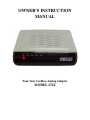
OWNER’S INSTRUCTION
MANUAL
Four Line Cordless Analog Adapter
MODEL 2742
Table of Contents
2742 FEATURE LIST................................................................................................................ 1
IMPORTANT SAFETY INSTRUCTIONS ................................................................................ 2
1. UNPACKING AND INSTALLATION................................................................................... 3
1.1. Box Contents ...................................................................................................................... 3
1.2. Telephone Part Identification............................................................................................... 4
2. INSTALLATION ................................................................................................................... 5
2.1. Overview........................................................................................................................ 5
2.2. Before Installation .......................................................................................................... 5
2.3. Initial Configuration ....................................................................................................... 5
2.3.1. Standard Configuration .......................................................................................... 5
2.3.2. Private Lines .......................................................................................................... 5
2.3.3. Unconnected Lines................................................................................................. 5
2.3.4. Line 1..................................................................................................................... 5
2.4. Desk Mount.................................................................................................................... 5
2.5. Wall Mount..................................................................................................................... 6
2.6. Verify Proper Installation ................................................................................................ 6
3. CONFIGURATION MODIFICATION .................................................................................. 7
3.1. Change Default Setting ................................................................................................... 7
3.2. Station Name Assignment ............................................................................................... 8
4. TELEPHONE OPERATION.................................................................................................. 9
4.1. Making and Answering Intercom Calls ........................................................................... 9
4.2. Making and Answering CO Line Calls............................................................................ 9
4.3. Hold ............................................................................................................................... 9
4.3.1. Hard Hold.............................................................................................................. 9
4.3.2. Placing a Call on System Hold ............................................................................... 9
4.4. Transfer .......................................................................................................................... 9
4.4.1. Attended Transfer................................................................................................... 9
4.4.2. Blind Transfer ........................................................................................................ 9
4.5. Conference ....................................................................................................................10
4.6. Three Way Calling ........................................................................................................10
4.7. Caller ID........................................................................................................................10
4.7.1. Incoming call ........................................................................................................10
4.7.2. Call Waiting Caller ID ..........................................................................................10
4.8. Intercom Calls ...............................................................................................................10
4.8.1. Intercom while Idle ...............................................................................................11
4.8.2. Intercom while on an Outside Call ........................................................................11
4.9. Paging ...........................................................................................................................11
4.9.1. Single Page ..........................................................................................................11
4.9.2. All Page ...............................................................................................................11
5. USING STANDARD TELEPHONES...................................................................................11
5.1. Line Status.....................................................................................................................11
5.2. Calls on Hold.................................................................................................................11
5.3. Call Privacy...................................................................................................................11
5.4. Intercom ........................................................................................................................11
5.5. Fax Machines and Modems ...........................................................................................12
APPENDIX A - Installation Worksheet .....................................................................................13
APPENDIX B - Trouble Shooting Guide ..................................................................................14
APPENDIX C - DTMF Operating Codes..................................................................................15
FCC INFORMATION...............................................................................................................16
TELEPHONE REPAIR.............................................................................................................17
LIMITED WARRANTY...........................................................................................................18
THANK YOU
FOR PURCHASING THE
2742
Four Line Cordless Analog Adapter
We want you to know all about your new Cordless Telephone Adapter.
To get the most from your Cordless Adapter, please take time to read this guide thoroughly.
We have included information in your Owner’s Instruction Manual on how to install it, the features it
provides, and the services you can expect from its use.
The 2742 is one of Cortelco’s 7 Series 4-Line Telephone Units. It is part of a Four-Line system
consisting of up to 16 stations of 2740's, 2742's, or 2750's. The 2742 Cordless Analog Adapter will
allow a cordless telephone or other analog device such as a fax machine or modem to be attached to
your 4-Line system
Information on the other products in Cortelco’s 7 Series can be found on our website at
www.cortelco.com.
2742 FEATURE LIST
EXPANDABLE UP TO 16 PHONES – Up to 16 units can be connected together.
INTERCOM - Call any other phone in your system.
PAGING - Make an announcement through the speaker of a single 2740/2750, or through all the 2740/2750's at
once.
TRANSFER - Answer a call and transfer it to any phone in the system.
PHONE LINE INDICATION - See at a glance which lines are in use.
UP TO 4 LINES - Access up to four separate phone lines.
CALLER ID AND CALL WAITING CALLER ID - For each line subscribed to this service, you may view the
Caller ID information for all incoming calls.
1
PLEASE READ BEFORE INSTALLING AND USING YOUR NEW
TELEPHONE EQUIPMENT.
IMPORTANT SAFETY INSTRUCTIONS
Always follow basic safety precautions when using your telephone equipment to reduce the risk of
fire, electrical shock, and injury.
1. Read and understand all instructions in the Owner’s Instruction Manual.
2. Read all warnings and follow all instructions marked on the product.
3. Unplug this product from the wall outlet before cleaning. Use a damp cloth for cleaning. Do not
use liquid or aerosol cleaners.
4. Do not use the 2742 Cordless Adapter near water. For example, do not use near a bathtub, wash
bowl, kitchen sink, laundry tub, swimming pool, or in a wet basement.
5. Do not place this product on an unstable cart or stand. The product may fall causing serious
damage to the product.
6. Do not place any objects on the telephone line cord. Do not locate the cordless adapter where the
line cords will be walked on.
7. Do not block or cover ventilation slots and openings in the top of the cordless adapter. The
openings should never be blocked by placing a book or paper on top of the adapter. The adapter should
never be placed near or over a radiator or heat register..
8. Never spill liquid on the cordless adapter or push objects of any kind through ventilation slots.
Liquid or objects may touch dangerous voltage points or short out parts that could result in a risk of fire
or electrical shock.
9. Do not disassemble this product. Opening or removing covers may expose you to dangerous
voltages or other risks. Incorrect reassembly can cause electrical shock when the product is
subsequently used.
10. Do not overload outlets and extension cords. Some telephones require AC power from an outlet.
Overloading the outlets can result in the risk of fire or electric shock.
11. Avoid using a telephone (other than a cordless type)during a local thunderstorm. There may be
a remote risk of electrical shock from lightning.
12. Use only the class 2 power transformer indicated in this manual.
13. Do not use a telephone to report a gas leak in the vicinity of the leak.
2
1.
UNPACKING AND INSTALLATION
1.1.
Box Contents
The following items should be packed with your 2742. Please contact your dealer if any of them is
missing.
2742 Adapter (Main Body)
1 pcs
Line Cord 7ft
2 pcs
Power Adapter (Transformer 9VDC 500 ma)
1 pcs
3
1.2.
Telephone Part Identification
1
Line 1 & 2 Input Jack
5
Analog Telephone Jack
9
Line 2 Indicator
2
Line 3 & 4 Input Jack
6
Power Transformer
10
Line 3 Indicator
3
Line 1 & 2 Output Jack
7
Power Indicator
11
Line 4 Indicator
4
Line 3 & 4 Output Jack
8
Line 1 Indicator
4
2.
INSTALLATION
2.1. Overview
The 2742 is part of the 7 Series Multi-line phone system. Up to 16 instruments may be connected in
this system. All these devices use conventional telephone wiring. Total wiring runs between stations
may not exceed 600 feet.
2.2. Before Installation
In order to install your telephones correctly, you must determine the incoming wiring configuration. In
most cases, incoming lines will be terminated in either RJ-11 Single Line Jacks or RJ-14 Double Line
Jacks. If you are not sure of your incoming line configuration, contact your telephone line installer.
All connection between the wall jacks and the telephones should be done with the provided twisted pair
modular line cords. Please be sure that your modular cords have at least 4 wires in them. If you have
RJ-11 jacks, you will need two line adapters (not included) to connect to the 2742. These couplers
should be available where you purchased your 2742.
2.3
Initial Configuration
2.3.1 Standard Configuration
The 2742 is initially configured so that each line is common at all stations. In other words, Line 1 at
each telephone is connected to the same incoming line; Line 2 at each station is connected to the same
incoming line, etc. This is commonly known as a “square system.” If this is suitable for your
installation, you only need to connect the telephones to the telephone lines.
2.3.2 Private Lines
A private line is a telephone number that is connected to only one telephone in the system. No other
phones in the system have access to this telephone line.
2.3.3 Unconnected Lines
It is also permissible to leave one or more lines unconnected.
2.3.4 Line 1
Line 1 MUST be connected to the same incoming line on all phones for the system to function
correctly. Line 1 cannot be a DSL or VoIP line.
2.4.
a.
b.
Desk Mount
Connect the power transformer to the jack on the back of the 2742. Plug the transformer into a
wall outlet which is not controlled by a wall switch. Use only a 9V DC 500mA, Class 2
transformer.
Connect the line cords. If you have RJ-14 line jacks, you need only connect 4wire line cords
between the wall jacks and the jacks in the base of the 2742. If you have RJ-11 line jacks,
you will need 2 line couplers as discussed in Section 3.3.2. Note that the jacks on the 2742
are numbered L1/L2 and L3/L4. Connect your incoming lines accordingly. Use the first two
jacks as Line In.
5
2.5.
a.
b.
c.
Wall Mount
Mount 2742 to the wall.
Connect the line cords as described above.
Connect the power transformer to the jack on the back of the 2742. Plug the transformer into a
wall outlet which is not controlled by a wall switch. Use only a 9V DC 500mA, Class 2
transformer.
2.6. Verify Proper Installation
This procedure should be used at each telephone after initial installation. It may also be used if you are
having problems with your system. First, verify the three items below at each telephone in the system.
a..
b.
c.
Verify that the AC power transformer is connected to the 2742 and to the mains power.
Verify that Line 1 is connected to the 2742.
Verify that a station number has been assigned. Go off hook on your cordless phone and dial
another station in your system (01 – 16). The phone should ring and display the incoming
station number. Note that this assumes that the system contains one or more 2740s or 2750s.
Now, verify that Line 1 has been connected correctly to all telephones.
d.
Go off hook on your cordless phone and dial 81. Verify that the Line 1 LED is red at each other
station.
To verify the connection of lines 2-4, perform the following steps at each telephone. Note that this
assumes that all lines are connected to all telephones. Remember that Lines 2, 3, and 4 may not be
common.
e.
f.
g.
For Line 2, go off hook on your cordless phone and dial 82. Verify that the Line 2 LED is red at
each other station.
For Line 3, go off hook on your cordless phone and dial 83. Verify that the Line 3 LED is red at
each other station.
For Line 4, go off hook on your cordless phone and dial 84. Verify that the Line 4 LED is red at
each other station.
Note: The cordless adapter will show lines that are seized by other 4 line units. This is shown by a red
led on the front of the unit.
6
3.
CONFIGURATION MODIFICATION
The default settings after initial power up are given in the table below.
SETTING
AVAILABLE OPTIONS
Station Number: 01
Station 02 to 16
CO1: Ringer On
On/Off
CO2: Normal, Ringer On
Normal w/ Ringer On
Normal w/ Ringer Off
Unconnected
CO3: Normal, Ringer On
Normal w/ Ringer On
Normal w/ Ringer Off
Unconnected
CO4: Normal, Ringer On
Normal w/ Ringer On
Normal w/ Ringer Off
Unconnected
Flash Time for Cordless Telephone: 600ms
300ms/600ms
3.1.
Change Default Setting
Each station must be assigned a different station number.
a.
Go off hook from the cordless telephone and get internal dial tone.
b.
Dial 6XXYYYYZ6 (see following sections)
XX = The station number to assign, ie; 01 to 16
YYYY = The CO Type setting for each CO Line
0 = Unconnected
1 = Normal w/ Ringer On
2 = Normal w/ Ringer Off
Z = The Flash Timer setting. The two possible setting are
3 = 300ms
6 = 600ms.
The standard setting is 600ms.
c.
c.
If the string is invalid, a no action beep will be heard.
Dial tone will be heard again.
Hang up to complete the process.
For example, to set station 01 with all four lines with normal ringer on and 600 ms flash time. Dial
“601111166”.
7
3.2. Station Name Assignment
A name may be assigned to each 4-Line telephone unit. This name will display during Intercom calls.
Name assignment must be done from Station 01 and must be done with a 2740 or 2750 telephone.
To assign a name to a station:
a.
Press MENU. The display will read “Phone Setting”
b.
Press the soft key under ENTER.
c.
Press the Down Arrow repeatedly until the display reads “Station Naming”
d.
Press the soft key under ENTER. The display will show the currently stored name for station
#01, or indicate “No Name” if no name has yet been given to station #01.
e.
Press soft Key under CHANGE if you wish to store a new name for station #01, or press
DOWN ARROW repeatedly until you see the station number that you want to name, and then
press the soft key under CHANGE.
f.
Use the dial pad numbers to enter the name for the desired station.
g.
Press the soft key under SAVE.
Repeat steps “a” through “g” for any additional stations you wish to name.
After assigning a Station Name at Station #01, it may take twenty four hours to update all
telephones.
The table below shows the dial pad numbers to press for different letters and special characters.
Note that you can press the 0, *, and # buttons if you want those characters, and you can press the
down arrow button below the display to leave an empty space. Press the DELETE button to make
corrections.
0
0
1
,
-
'
&
.
(
)
2
A
B
C
a
b
c
2
3
D
E
F
d
e
f
3
4
G
H
I
g
h
i
4
5
J
K
L
j
k
l
5
6
M
N
O
m
n
o
6
7
P
Q
R
S
p
q
r
8
T
U
V
t
u
v
8
9
W
X
Y
w
x
y
9
*
*
#
#
8
1
s
7
4.
TELEPHONE OPERATION
4.1. Making and Answering Intercom Calls
To make an intercom call from a telephone connected to the Cordless Adapter, go off hook and dial the
desired station number (01 through 16). When receiving an intercom call, your cordless telephone will
ring but no line LED will light. If you have Caller ID on your telephone, the calling station
information will be displayed.
4.2. Making and Answering CO Line Calls
To make a call on a CO line, dial 9, for the first open line or dial a code for an individual line. The
code for Line 1 is 81. The code for Line 2 is 82. The code for Line 3 is 83, and the code for Line 4 is
84. Any ringing line will be answered by going off hook.
4.3. Hold
4.3.1. Hard Hold
Many cordless telephones have a built in hold feature. This type of hold does not put the line on
system hold and prevents any one else picking up the line unless privacy has been removed from
system.
4.3.2. Placing a Call on System Hold
To place an outside call on System Hold, press the Flash button. To take the call off hold, press the
Flash button. While a caller is on hold, you can not go on hook without receiving a ring back. While a
call is on hold, it can be taken off hold by any 4-line telephone connected to that line simply by
accessing the line.
Note: An intercom call cannot be placed on hold.
While having a conversation on a CO line, if a call comes in on another line, you can place the first call
on hold via flash, and answer the call by dialing the trunk code for the flashing line.
4.4. Transfer
CO line calls may be transferred to other 4 – line units.
4.4.1. Attended Transfer
a.
Press Flash to place the CO Line on System Hold.
b.
Dial the target Station number. After the station answers, announce your call and hang up.
4.4.2. Blind Transfer
a.
Place CO Line on System Hold with Flash.
b.
Dial the target Station number preceded by a “*”. After the called station starts ringing,
disconnect.
Example: To transfer to station 03, press Flash, dial “*03”, and disconnect.
9
4.5.
Conference
The 2742 will not conference internal stations with an outside line. To conference one CO Line with
another, follow the procedure below.
a.
With a call established on a CO Line, press Flash to place it on hold.
b.
Dial the code for second CO Line.
c.
After the second CO Line answers, press Flash. The conference is now established.
4.6.
Three Way Calling
The CO Line Three Way Call feature is provided by the telephone switch that provides the CO Lines.
You must subscribe to this feature from the telephone company. To perform a three way call on an
outside line.
a.
b.
c.
d.
e.
With a call established on a CO Line, press Flash to place it on hold.
Press the 7 button on your dial. This sends a Flash to the CO line.
Dial the CO number that you want to conference.
After the called number answers, press the Flash button.
Press the 7 button. The 3 Way call will be established.
4.7. Caller ID
The Caller ID feature works in conjunction with Caller ID service offered by your local telephone
company. The 2742 will provide caller ID information to the cordless telephone connected to the
adapter. In order for this feature to work, you must subscribe to the Caller ID service from your local
telephone company. Call waiting caller ID may not be available in all areas that offer caller ID service,
and may cost more than basic number caller ID service. Also, please note that you must order Caller ID
service separately for each line on which the service is desired.
4.7.1. Incoming call
The caller ID information will be displayed automatically.
4.7.2. Call Waiting Caller ID
If a call comes in during an established call, the display will automatically show the caller ID
information. To answer that call, press Flash and then press 7. To return to the previous call, press
Flash and then press 7 again.
The call record will show the Caller Name, Call Number, and CO Line.
4.8. Intercom Calls
You may place an intercom call by dialing the two-digit station number (01 – 16) of the desired station.
When you place an intercom call, if the called station is set to INTERCOM RING, you may speak to
the station as soon as they answer.
If the called station is set to INTERCOM VOICE or INTERCOM HANDSFREE, you may speak to
the station after you hear the confirming tone.
Note: If the intercom line is busy or the called station is set to DO NOT DISTURB, you will hear a no
action tone.
10
4.8.1. Intercom while Idle
a.
Go off hook with your cordless phone.
b.
Dial the two-digit station number of the station you wish to intercom.
c.
Hang up to end the conversation.
4.8.2. Intercom while on an Outside Call
a.
Press the Flash button. The outside call is placed on hold.
b.
Dial the two-digit station number of the station you wish to intercom.
c.
Press the Flash button to return to your CO Line call.
4.9. Paging
The Paging feature allows you to make announcements to other 2750/2740 stations in the system.
Note: You may Page another station only if it is not in use, does not have DO NOT DISTURB
activated, and is not set to BLOCK PAGES. If the station is in any of these conditions, you will hear a
no action tone.
4.9.1. Single Page
a.
Go off hook with your cordless phone.
b.
Dial “#” and the two-digit station number of the station you wish to page.
c.
After you hear the paging tone, make your announcement.
4.9.2. All Page
The All Page feature enables you to make announcements through all of the other 2750/2740 stations.
When you make an All Page, your announcement, preceded by a double paging alert tone, will be heard
at all the phones that are not in use and do not have their DO NOT DISTURB or BLOCK PAGE
activated. To perform an All Page:
a.
Go off hook with your cordless phone.
b.
Dial ##. After you hear the paging tone, make your announcement.
5.
USING STANDARD TELEPHONES
The 2742 4-Line Cordless Adapter supports connecting a single line telephone to the local 4 – line
system consisting of 2740's, 2742's, or 2750's. It will not work with other standard telephones
connected to the CO Lines.
5.1. Line Status
The line status indicators of the 2742 cordless adapter will only recognize the status of lines taken off
hook by 2740's, 2750's or 2742's.
5.2. Calls on Hold
When a call is placed on hold at a 2742 telephone, it can not be taken off hold at a standard telephone.
5.3. Call Privacy
Call privacy is not observed by standard telephones. A standard telephone may pickup on a line at any
time. .
5.4. Intercom
Standard telephone units cannot use the intercom feature to communicate with 4-Line telephones.
11
5.5. Fax Machines and Modems
You may connect modems or fax machines to any of your lines. The line indicators of the 2740/2750
telephones will light when these devices are using a line. However, the 2742 Cordless Adapter will not
show that the lines are in use.
12
APPENDIX A
Installation Worksheet
Note: Line 1 must be common to all system sets
Station
Number
Station
Type
User's Name or Telephone
Location
Line 1
Line 2
Line 3
Line 4
Tel#_________ Tel#_________ Tel#_________ Tel#_________
01
Common
Common or
Unconnected
Common or
Unconnected
Common or
Unconnected
02
Common
Common or
Unconnected
Common or
Unconnected
Common or
Unconnected
03
Common
Common or
Unconnected
Common or
Unconnected
Common or
Unconnected
04
Common
Common or
Unconnected
Common or
Unconnected
Common or
Unconnected
05
Common
Common or
Unconnected
Common or
Unconnected
Common or
Unconnected
06
Common
Common or
Unconnected
Common or
Unconnected
Common or
Unconnected
07
Common
Common or
Unconnected
Common or
Unconnected
Common or
Unconnected
08
Common
Common or
Unconnected
Common or
Unconnected
Common or
Unconnected
09
Common
Common or
Unconnected
Common or
Unconnected
Common or
Unconnected
10
Common
Common or
Unconnected
Common or
Unconnected
Common or
Unconnected
11
Common
Common or
Unconnected
Common or
Unconnected
Common or
Unconnected
12
Common
Common or
Unconnected
Common or
Unconnected
Common or
Unconnected
13
Common
Common or
Unconnected
Common or
Unconnected
Common or
Unconnected
14
Common
Common or
Unconnected
Common or
Unconnected
Common or
Unconnected
15
Common
Common or
Unconnected
Common or
Unconnected
Common or
Unconnected
16
Common
Common or
Unconnected
Common or
Unconnected
Common or
Unconnected
Station Types: 2740, 2750, or 2742
13
APPENDIX B
Trouble Shooting Guide
If you are having difficulty with your 2742 Cordless Adapter, please review the issues below and their
solutions. If you do not find your problem or you have other questions, please call 662-287-5281 and
request technical assistance.
The Cordless Adapter does not work.
Check all connections and make sure that they are securely in place.
Make sure that the AC transformer is plugged into a jack not connected
to a wall switch. Check to make sure that the status indicator lamp is
blinking. If it is not, unplug and then replug the AC power cord. If the
status indicator still fails to start blinking, check your wall jack by
plugging another device such as a lamp into the outlet to make sure
that it is working properly.
The Cordless Adapter is connected
properly, but still does not work.
The problem may be with the telephone wiring. If possible, check
your jack wiring by testing a four line telephone at the jack where you
installed the Cordless Adapter. If the 4-line does not work, then your
wiring may be causing the problem.
The problem may be with your cordless telephone. Check to make
sure that your cordless telephone is working properly. Plug it into
another line jack to be sure. Make sure it is connected properly to the
Cordless Adapter.
When you connect your cordless
adapter, the station number is not
correct or other settings need to be
changed.
See Section 3. Configuration Modification
Other Problems
Make sure that you have followed the instructions in this User's Guide.
If you continue to have problems, please call us at 662-287-5281 for
technical assistance.
14
APPENDIX C
DTMF Operating Codes
The following dial codes are used for control of your cordless adapter
DTMF CODE
OPERATION
9
For seizing an available CO Line (scanning from CO1 thru CO4)
81
For selecting CO-1.
82
For selecting CO-2
83
For selecting CO-3
84
For selecting CO-4
01 through 16
For dialing intercom stations
#01 through #16
For Paging a selectable 2740/2750 station
##
To Page across all 2740/2750s
Flash
To put a Line on Hold (only one CO line can be put on hold) and to retrieve a held call
Flash and 7
To send a Flash out on an active CO Line
*01 through *16
To transfer an on-hold CO line to another station
6XXYYYYZ6
For programming the cordless adapter
XX = Station Number
Y = CO Line
Z = Flash Timer
See section 3 for instructions on setting up cordless adapter.
15
FCC INFORMATION
This equipment complies with Part 68 of the FCC rules. On the base of this equipment is a label that contains, among other
information, the FCC registration number and ringer equivalence number (REN) for this equipment. If requested, this
information must be provided to the telephone company.
The FCC requires that you connect your telephone to the telephone network through a modular telephone outlet or jack,
which must comply with FCC part 68 rules. The modular telephone outlet or jack to which your 2742 Cordless Adapter
must be connected is a USOC RJ11C or RJ14C. The Facility Interface code (FIC) for your 2742 Cordless Adapter is 02LS2
which is a 2- wire, Local Switched Access, Loop-start.
The Ringer Equivalence Number (REN) is used to determine the quantity of devices which may be connected to the
telephone line. The REN for your 2742 Cordless Adapter is 0.2. Excessive RENs on the telephone line may result in the
devices not ringing in response to an incoming call. In most areas, the sum of the RENs should not exceed five (5). To be
certain of the number of devices that may be connected to the line, as determined by the total RENs, contact the telephone
company to determine the maximum REN for the calling area.
If the 2742 Cordless Adapter causes harm to the telephone network, the telephone company will notify you in advance that
temporary discontinuance of service may be required. If advance notice isn’t practical, the telephone company will notify
you as soon as possible. Also, you will be advised of your right to file a complaint with the FCC if you believe it is
necessary. The telephone company may make changes in its facilities, equipment, operations or procedures that could affect
the operation of the equipment. If this happens, the telephone company will provide advance notice in order for you to make
the necessary modifications in order to maintain uninterrupted service.
If trouble is experienced with your 2742 Cordless Adapter, please contact Cortelco Technical Support, 662-287-5281 for
repair and/or warranty information. If the trouble is causing harm to the telephone network, the telephone company may
request you remove the equipment from the network until the problem is resolved. Do not attempt to repair or modify this
equipment.
Please contact Cortelco for information on obtaining service for this product. This equipment cannot be used on public coin
service provided by the telephone company. Connection to Party Line Service is subject to state tariffs. (Contact the state
public utility commission, public service commission or corporation commission for information.) This equipment is
hearing-aid compatible. This equipment is capable of providing users access to interstate providers of operator services
through the use of access codes. Modification of this equipment by call aggregators to block access dialing codes is a
violation of the Telephone Operator Consumers Act of 1990.
Warning: Changes or modifications to this unit not expressly approved by the party responsible for compliance could void
the user’s authority to operate the equipment.
NOTE: This equipment has been tested and found to comply with the limits for a Class B digital device, pursuant to Part 15
of the FCC Rules. These limits are designed to provide reasonable protection against harmful interference in a residential
installation. This equipment generates, uses, and can radiate radio frequency energy and, if not installed and used in
accordance with the instructions, may cause harmful interference to radio communications. However, there is no guarantee
that interference will not occur in a particular installation. If this equipment does cause harmful interference to radio or
television reception which can be determined by turning the equipment off and on, the user is encouraged to try to correct
the interference by one or more of the following measures:
Reorient or relocate the receiving antenna.
Increase the separation between the equipment and receiver.
Connect the equipment into an outlet on a circuit different from that to which the receiver is connected.
Consult the dealer or an experienced radio TV technician for help.
This Class B digital apparatus complies with Canadian ICES-003. Cet appareil numérique de la classe B est conforme à la
norme NMB-003 du Canada.
Automatic Dialers
When programming emergency numbers and/or making test calls to emergency numbers, remain on the line and briefly
explain to the dispatcher the reason for the call before hanging up. Perform such activities in the off-peak hours, such as
early morning hours or late evenings.
16
TELEPHONE REPAIR
DO NOT ATTEMPT TO REPAIR THIS PRODUCT YOURSELF. Telephones manufactured by
CORTELCO must be returned to us for repair. You can return your telephone to CORTELCO for repair
or replacement in accordance with our LIMITED WARRANTY.
CORTELCO warrants THIS PRODUCT against defects in material and workmanship in accordance
with our LIMITED WARRANTY. If your telephone is returned for repair, include a copy of your sales
receipt containing the date-of-purchase. DO NOT INCLUDE THE ORIGINAL SALES RECEIPT. If
date-of-purchase is not included, the factory date printed on the label on the bottom of your telephone
will be used as the date-of-purchase. The factory date allows six months for distribution and sale of this
product. If you return your telephone for repair, the warranty period is not extended. The original dateof-purchase continues to apply to your warranty.
OUT-OF-WARRANTY REPAIR We will repair this product for a nominal fee after the LIMITED
WARRANTY has expired if you send it to us in a complete and undamaged condition. The repaired
unit will be shipped to you C.O.D., freight collect.
RETURN-FOR-REPAIR PACKAGING If you are returning a unit to us for repair, package it carefully,
preferably in the original carton. Be sure to include your return address, a copy of the sales receipt
showing date-of-purchase, and a note with your name, telephone number, return street address, and a
brief description of the problem that you have with your Telephone. Shipping must be prepaid. If the
telephone is in warranty, it will be repaired or replaced, at our option, at no cost to you, and it will be
returned shipping prepaid. Ship your telephone (shipping prepaid) to:
CORTELCO
REPAIR CENTER
1703 SAWYER ROAD
CORINTH, MS 38834
17
LIMITED WARRANTY
If you purchased this product new in the U.S. or Puerto Rico, CORTELCO warrants it against defects
in material and workmanship for a period of one (1) year from the date of original purchase. This
warranty is in lieu of all other express warranties. During the warranty period, CORTELCO agrees to
repair or, at its option, replace the defective product, or any part of it without charge for parts or labor.
This is your exclusive remedy. This warranty does not cover damage resulting from accident, misuse,
abuse, improper installation or operation, lack of reasonable care, the affixing of any attachment not
provided by CORTELCO with the product and loss of parts. The warranty is voided in the event any
unauthorized person alters or repairs the unit. Telephone companies use different types of equipment
and offer various types of services to customers. CORTELCO does not warrant that this product is
compatible with the type of equipment of any particular phone company or the services provided
by it.
CORTELCO DISCLAIMS ANY IMPLIED WARRANTY, INCLUDING THE WARRANTY OF
MERCHANTABILITY AND THE WARRANTY OF FITNESS FOR A PARTICULAR PURPOSE, AS
OF THE DATE ONE YEAR FROM THE ORIGINAL PURCHASE OF THE PRODUCT.
CORTELCO ASSUMES NO RESPONSIBILITY FOR ANY SPECIAL, INCIDENTAL OR
CONSEQUENTIAL DAMAGES.
THIS WARRANTY GIVES YOU SPECIFIC LEGAL RIGHTS, AND YOU MAY HAVE OTHER
RIGHTS WHICH VARY FROM STATE TO STATE. SOME STATES DO NOT ALLOW THE
EXCLUSION OR LIMITATION OF SPECIAL, INCIDENTAL OR CONSEQUENTIAL DAMAGES
OR LIMITATIONS ON HOW LONG AN IMPLIED WARRANTY LASTS, SO THE ABOVE
EXCLUSION AND LIMITATION MAY NOT APPLY TO YOU.
If failure occurs and your telephone is in warranty, service shall be provided by returning it to
CORTELCO
Repair Center,
1703 Sawyer Road,
Corinth, Mississippi 38834,
shipping prepaid. The product will be repaired or replaced if examination by us determines the product
to be defective. Telephones received damaged as a result of shipping will require you to file a claim
with the carrier.
Version 1.4
18