1
ENCORE
Operator's
Manual
S30/L30
U.S. Patent No. 6,105,192; No. 6,557,207; No. 6,760,947
READ THIS BOOK
CAUTION: Read the Operator's Manual before using the appliance.
This book has important information for the use and safe operation of this machine. Failure to read this
book prior to operating or attempting any service or maintenance procedure to your Clarke machine could
result in injury to you or to other personnel; damage to the machine or to other property could occur as
well. You must have training in the operation of this machine before using it. If operator(s) cannot read
this manual, have it explained fully before attempting to operate this machine.
Si Ud. o sus operadores no pueden leer el Inglés, se hagan explicar este manual completamente antes
de tratar el manejo o servicio de esta máquina.
All directions given in this book are as seen from the operator’s position at the rear of the machine.
For new books write to: Clarke®, 2100 Highway 265, Springdale, Arkansas 72764.
Form No. 70762A
1/08
Clarke®
Printed in the U.S.A.
Table of Contents
Operator Safety Instructions ............................................................................................................................ 3
Introduction & Machine Specifications ............................................................................................................. 5
Procedures for Transporting Machine ............................................................................................................. 6
Symbols Used on Encore S30/L30 ................................................................................................................. 8
Machine Control Panel ..................................................................................................................................... 10
Machine Controls and Features ...................................................................................................................... 11
How to Prepare the Machine for Operation ...................................................................................................... 12
How to Install the Batteries ................................................................................................................ 12
Battery Maintenance ........................................................................................................................... 13
How to Charge the Batteries ............................................................................................................. 14
How to Adjust Brush Cleaning Path .................................................................................................. 15
How to Install a Brush or Pad Driver ................................................................................................. 15
How to Remove a Brush or Pad Driver .............................................................................................. 16
How to Operate the Machine ............................................................................................................................ 16
How to Operate the Squeegee .......................................................................................................... 16
Filling the Solution Tank .................................................................................................................... 16
Operating the Machine ....................................................................................................................... 17
How to Clean a Dirty Floor ................................................................................................................. 18
Maintenance ..................................................................................................................................................... 19
Procedures Before Work is Began .................................................................................................... 19
Procedures to Perform at the End of Work ........................................................................................ 20
Procedures to Perform Every Week ................................................................................................... 21
Maintenance for the Squeegee .......................................................................................................... 22
How to Adjust the Squeegee ............................................................................................................. 22
How to Clean the Solution Line ......................................................................................................... 23
How to Center or Off set Brushhead ................................................................................................. 23
Accessories ...................................................................................................................................................... 25
SECTION II - Parts and Service Manual
How to Correct Problems in the Machine ........................................................................................................ 26
Encore S30/L30 Final Assembly Drawing ....................................................................................................... 28
Parts List ............................................................................................................................................ 29
Recovery Tank Drawing ................................................................................................................................... 30
Parts List ............................................................................................................................................ 31
Solution Tank Assembly Drawing .................................................................................................................... 32
Parts List ............................................................................................................................................ 33
Rear Panel Assembly Drawing ........................................................................................................................ 34
Parts List ............................................................................................................................................ 35
Control Panel Assembly Drawing .................................................................................................................... 36
Parts List ............................................................................................................................................ 37
Squeegee Lift Assembly Drawing ................................................................................................................... 38
Parts List ............................................................................................................................................ 39
Squeegee Assembly Drawing ......................................................................................................................... 40
Parts List ............................................................................................................................................ 41
Frame Axle Assembly Drawing ........................................................................................................................ 42
Parts List ............................................................................................................................................ 43
Brush Head Assembly Drawing ...................................................................................................................... 44
Parts List ............................................................................................................................................ 45
Optional Brake Assembly Drawing and Parts List "S" Model .......................................................................... 46
Optional Brake Assembly Drawing and Parts List "L" Model .......................................................................... 48
Gearbox Assembly Drawing and Parts List ..................................................................................................... 49
Brush Motor Assembly Drawing and Parts List ............................................................................................... 50
Transaxle Repair Parts .................................................................................................................................... 51
Battery Charger (40512A & 40513A) Drawing and Parts List ......................................................................... 52
Battery Charger (40512B 7 40506B) Drawing and Parts List ......................................................................... 53
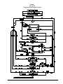
Encore S30 Connection Diagram .................................................................................................................... 53
Encore S30 Electrical Schematic ..................................................................................................................... 54
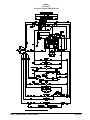
Encore L30 Connection Diagram .................................................................................................................... 55
Encore L30 Electrical Schematic ..................................................................................................................... 56
Page
-2-
Clarke® Operator's Manual -Encore S30/L30
OPERATOR SAFETY INSTRUCTIONS
WARNING
AVERTISSEMENT
ADVERTENCIA
DANGER:
Failure to read and observe all DANGER statements could result in
severe bodily injury or death. Read and observe all DANGER
statements found in your Owner's Manual and on your machine.
WARNING:
Failure to read and observe all WARNING statements could result
in injury to you or to other personnel; property damage could
occur as well. Read and observe all WARNING statements found in
your Owner's Manual and on your machine.
CAUTION:
Failure to read and observe all CAUTION statements could result in
damage to the machine or to other property. Read and observe all
CAUTION statements found in our Owner's Manual and on your
machine.
DANGER:
Failure to read the Owner's Manual prior to operating or attempting any service or
maintenance procedure to your Clarke machine could result in injury to you or to
other personnel; damage to the machine or to other property could occur as well.
You must have training in the operation of this machine before using it. If you or
your operator(s) cannot read English, have this manual explained fully before
attempting to operate this machine.
DANGER:
Operating a machine that is not completely or fully assembled could result in injury
or property damage. Do not operate this machine unless it is completely
assembled. Inspect the machine carefully before operation.
DANGER:
Machines can cause an explosion when operated near flammable materials and
vapors. Do not use this machine with or near fuels, grain dust, solvents, thinners,
or other flammable materials. This machine is not suitable for picking up hazardous
dust. Use only commercially available floor cleaning waxes intended for machine
operation.
DANGER:
Lead acid batteries generate gases which can cause an explosion. Keep sparks
and flames away from batteries. Do not smoke around the machine. Charge the
batteries only in an area with good ventilation. Make sure that the AC charger plug
is unplugged from the wall receptacle before connecting or disconnecting the DC
plug to or from the battery pack.
DANGER:
Working with batteries can be dangerous! Always wear eye protection and
protective clothing when working near batteries. Remove all jewelry. Do not put
tools or other metal objects across the battery terminals, or the tops of the
batteries.
DANGER:
Using a charger with a damaged power cord could result in an electrocution. Do
not use the charger if the power cord is damaged.
WARNING:
Operating this machine from anywhere other than the back of the machine could result in
injury or damage. Operate this machine only from the rear.
WARNING:
This machine is heavy. Get assistance before attempting to transport or move it. Use
two able persons to move the machine on a ramp or incline. Always move slowly. Do
not turn the machine on a ramp. Do not use on surfaces having a gradient exceeding that
marked on the appliance. Read the "Procedures For Transporting" in this manual before
transporting as machine might topple over if not secured.
WARNING:
Machines can topple over and cause injury or damage if guided over the edges of stairs or
loading docks. Stop and leave this machine only on a level surface. When you stop the
machine, put all switches into their "OFF" position. Turn the key switch "OFF" and
remove the key.
Clarke® Operator's Manual - Encore S30/L30
Page -3-
Page
WARNING:
Maintenance and repairs performed by unauthorized personnel could result in damage or
injury. Maintenance and repairs must be performed by authorized Clarke personnel
only.
WARNING:
Any alterations or modifications of this machine could result in damage to the machine or
injury to the operator or other bystanders. Alterations or modifications not authorized by
the manufacturer voids any and all warranties and liabilities.
WARNING:
Electrical components of this machine can "short-out" if exposed to water or moisture.
Keep the electrical components of the machine dry. Wipe the machine down after each
use. This appliance is for dry use only and is not to be used or stored outdoors in wet
conditions.
WARNING:
Operating a machine without observing all labels and instructional information could result
in injury or damage. Read all machine labels before attempting to operate. Make sure all
of the labels and instructional information are attached or fastened to the machine. Get
replacement labels and decals from your Clarke distributor.
WARNING:
Wet floor surfaces can be slippery. Water solutions or cleaning materials used with this
type of machine can leave wet areas on the floor surface. These areas can cause a
dangerous condition for the operator or other persons. Always put "Caution" signs
around/near the area you are cleaning.
WARNING:
Improper discharge of waste water may damage the environment and be illegal.
The United States Environmental Protection Agency has established certain regulations
regarding discharge of waste water. City, state and national regulations regarding this
discharge may also be in effect in your area. Understand and follow the regulations in
your area. Be aware of the environment hazards of chemicals that you dispose.
WARNING:
Only use the brushes provided with the appliance or those specified in the Operator's
Manual. The use of other brushes may impair safety.
CAUTION:
Use of this machine to move other objects or to climb on could result in injury or damage.
Do not use this machine as a step or furniture. Do not ride on this machine.
CAUTION:
Your machine warranty will be voided if anything other than genuine Clarke parts are
used on your machine. Always use Clarke parts for replacement.
CAUTION:
This machine contains lead acid batteries. The batteries must be disposed of in an
environmentally acceptable manner.
-4-
Clarke® Operator's Manual -Encore S30/L30
Introduction & Machine Specifications
Introduction & Machine Specifications
Clarke’s newly designed Encore S30 and L30 automatic scrubbers are efficient and superior floor
cleaning machines. The Encore uses two brushes to scrub a path 30 inches wide. A squeegee wipes
the floor while the vacuum motor removes the dirty solution from the floor - all in one pass.
The Encore S30 comes complete with either four - 6 volt batteries or two - 12 volt batteries, one battery
charger, either two brushes or two pad drivers, and one operator’s manual.
The Encore L30 comes complete with four - 6 volt batteries, one battery charger, either two brushes or
two pad drivers, and one operator’s manual.
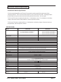
SPECIFICATIONS:
Model
Machine Power Supply
Encore L30
24 Volt D.C.,
(4) 6V 250 AH Deep Cycle Batteries or
(4) 6V 330 AH Deep Cycle Batteries
Pad or Brush
2 per machine
Traverse
Traverse Forward Speed
Traverse Reverse Speed
Battery Protection
Motor Vacuum
Solution Tank
Solution Level
Recovery Tank
Recovery Full Indicator
Parabolic Squeegee
Gimbal Style
Encore S30
24 Volt D.C.,
(2) 6V 195 AH Deep Cycle Batteries or
(4) 6V 250 AH Deep Cycle Batteries or
(4) 6V 330 AH Deep Cycle Batteries
3-Lug Driver Style
0.5 hp (0.4 kW) Transaxle
Variable to 250 ft./min (76 m/min)
Variable to 190 ft./min. (58 m/min)
Brush Assist
Not Applicable
Not Applicable
Squeegee Operation
Cleaning Swath
Motor, Brush
Brush / Pad Size
Brush Speed
Brush Pressure
Brush Solution Retention
Drive Wheels
Caster
Charger
Grade Cleaning
Length
Width
Height
Weight
Line of Sigh (from Operator
Height): 68 inches (173 cm)
Warranty
Noise
Vibration
Low Voltage
3/4 HP, 3 stage, Acoustical High Efficient Tangential
20 Gallons (76 liters)
Calibrated level indicator on rear of machine
20 Gallons (76 liters)
Electric Shut-Off
Swing type with breakaway feature, No tool operation feature
39 inches (99 cm) hard width with 41 inches (104 cm) flex blade width.
Reverse direction on floor and 3 - position manual lever style operation
30 inch (76 cm) adjustable head
0.75 HP (0,56 kW) 5.2:1 High Torque Gear Box
(2) 15 inch (38 cm)
200 RPM
0-150 lbs. / 0-68 kg.
Fiber Bristles
(2) 8 in. x 2 in. (20 cm x 5 cm) Neoprene tread
Dual 4 in. x 2 in. (10 cm x 5 cm)
24 V D.C., 25 Amp, 115/60 or 24 V D.C., 25 Amp, 230/50
5 Degree (6%)
2%
56 inches (142 cm)
28 inches (71 cm)
43 inches (109 cm)
871 lb / 395 kg
71 dBA
< 2.5 m/s2
Clarke® Operator's Manual - Encore S30/L30
7.5 feet (2.3 m)
Machine 3 Years, Polydur tanks- 8 years
Batteries- 18 months, pro-rated
71 dBA
<2.5 m/s2
Page -5-
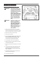
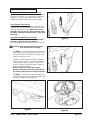
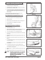
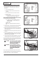
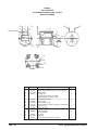
Procedures For Transporting
How to Put the Machine Into a Van or Truck
WARNING:
This machine is heavy. Get
assistance before attempting
to transport or move it. Use
two able persons to move the
machine on a ramp or
incline. Always move slowly.
Do not turn the machine on a
ramp. Do not stop and leave
the machine on a ramp or
incline. The loading ramp
must be a minimum of 32"
wide.
WARNING:
Machines can topple over if
guided over the edges of
stairs or loading docks and
cause injury or damage.
Stop and leave this machine
only on a level surface.
When you stop the machine,
put all switches into their
"OFF" position.
Figure #1
1. Make sure the loading ramp is at least eight
(8) feet (2.5m) long and a minimum of 32" (0.8m)
wide, and strong enough to support the machine.
2. Make sure the ramp is clean and dry.
3. Put the ramp in position.
4. Remove squeegee assembly, brush housing and
brush or pad driver before loading. Clarke
recommends that both the solution tank and
recovery tank are empty before loading.
5. Turn key switch "ON" (on L30 model only).
6. Align the machine on a level surface five (5) feet
(2 m) in front of the ramp.
7. Put the traverse knob at full speed (on L30 model
only).
8. For the L30 machine, push in either one of the
forward/reverse switches while pushing in the
white reverse switch. Back the machine up the
ramp. See figure 1.
9. For the S30 machine, push the machine backwards to the top of the ramp.
10. Turn the key switch "OFF".
Page
-6-
Clarke® Operator's Manual -Encore S30/L30
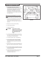
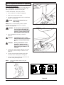
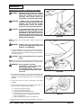
Procedures For Transpoting (cont.)
11. Fasten the machine to the vehicle. Clarke
recommends a strap over the top of the
machine and a strap to keep the machine from
rolling forward or backwards. If this is not
done, there is a possibility of the machine
toppling over. Four tie down points (2 along
each side of frame) are provided on machine for
securing machine.
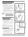
How to Remove the Machine From a Van or
Truck
1. Make sure there are no obstructions in the area.
2. Make sure the unloading ramp is at least eight
(8) feet (2.5m) long and a minimum of 32"
(0.8m) wide, and strong enough to support the
machine.
Figure #2
3. Make sure the ramp is clean and dry.
4. Put the ramp in position.
5. Unfasten the machine.
WARNING:
The machine is heavy.
Make sure you use two able
persons to assist in moving
the machine down the
ramp.
6. On S30 model, get two people to pull machine
off ramp. It is recommended that the "S" model
be unloaded in the forward position.
7. Turn the key switch "ON". (L30 model only)
8. Set the traverse center knob to the slowest
forward speed setting. Carefully and slowly,
drive the machine to the top of the ramp and
start down.
9. While pushing in the right or left forward/reverse
switch the machine will go forward. See figure
2.
10. As the machine begins to travel down the ramp,
push in the forward/reverse switch to maintain a
slow downward speed.
11. Replace squeegee assembly, brush housing,
and brush or pad driver after machine is
unloaded and ready to use.
Clarke® Operator's Manual - Encore S30/L30
Page -7-
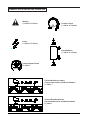
SYMBOLS USED ON ENCORE S30 and L30
Warning
("L Class" & "S Class')
Solution Control
("L Class" & "S Class")
Power
("L Class" & "S Class")
Brush Up/Down
("L Class" & "S Class")
Traverse Speed Control
("L Class")
Traverse Directions Forward
(Traverse and Solution, and Brush Rotation)
("L Class" )
Traverse Directions Reverse
(Traverse and Solution, and Brush Rotation)
("L Class" )
Page
-8-
Clarke® Operator's Manual -Encore S30/L30
SYMBOLS USED ON ENCORE S30 and L30
Solution/Brush Motors
("S Class" )
Warning Label
("L Class" & "S Class")
with parking brake
Warning Label
("L Class" & "S Class")
without parking brake
Clarke® Operator's Manual - Encore S30/L30
Page -9-
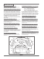
Machine Control Panel
Circuit Breakers (See Fig 3, Items "F", "G", "H", "I" & "J")
The circuit breaker reset buttons are located on the
rear cover. The breakers are located as follows:
Item F - Actuator Head (5 amp)
Item G - Vacuum Motor (30 amp)
Item H& I - Brush Motor (40 amp)
Item J - Traverse Motor (25 amp) (L30 only)
If a circuit breaker trips, determine which motor is not
operating and turn the key switch "OFF". Wait five
minutes and push the reset button back in. Turn the
key switch "ON" and try again. An authorized service
person should be contacted if the breaker trips again.
Key Switch (See Figure 3, Item "A")
The key switch turns "ON" the power to the control
panel. "O" is "OFF" and "I" is "ON".
Forward Reverse Switch (See Figure 3, Item "B")
On Traverse ("L") Model Only - The forward/reverse
switch turns the traverse motor "on" forward and if the
brush motors are in the down position, activates the
brush motors/solution control module. There is a two
second delay for the pad motor to stop after releasing
the switch. Either the right or the left switch can be
used. Use either switch in conjunction with the white
reverse switch to reverse the traverse motor.
"S" Model - These switches activate brush motors
and solution/control module if brush motors are in the
down position.
Control Handles (See Figure 3, Item "K")
The control handles are located at the rear of the
machine. They are used to guide the machine.
Solution Control Knob (See Figure 3, Item "L")
The solution control knob regulates the flow of chemical solution to the floor. To increase the flow, turn
knob clockwise. To decrease the flow, turn counter
clockwise. Full counter clockwise is OFF and full
clockwise is ON.
Battery Meter (See Figure 3, Item "C")
The battery meter indicates the relative charge on the
battery pack. Do not continue to run the machine
when the needle is in the "red" area. This will shorten
the life of the battery pack.
Brush Pressure Meter (See Figure 3, Item "D")
The pad pressure meter indicates the relative amount
of pressure the pad is putting on the floor. To maximize run time on a battery charge, keep the needle
towards the center of the green area.
Traverse Speed Knob (See Figure 3, Item "M")
To increase speed, turn knob clockwise.
Brush Motor Switch (See Figure 3, Item "N")
To activate brush motor, push brush position switch to
down position. Brush Motor and solution flow will
activate when the traverse buttons are pushed. To
shut brush motor off, hold brush position switch in up
position until actuator stops.
Reverse Switch (See Figure 3, Item "E")
On Traverse Model Only
The reverse switch, when used in conjunction with one
of the forward/reverse switches, causes the machine to
reverse directions. The reverse speed is 70% of the
forward speed.
Vacuum Motor Switch (See Figures 4 & 5, pg. 11)
To activate vacuum motor, lower squeegee handle.
Handle has two positions. Lowest position is
operating position and the middle position is transport
to clear vacuum hose.
Hour Meter (Not Illustrated) (Option)
The hour meter indicates the number of hours the
machine has operated. It runs only when the brush
motor is on.
K
E
A
M
K
B
B
C
N
G
L
FGH I J
K
D
H
Figure 3
Page
-10-
Clarke® Operator's Manual -Encore S30/L30
Machine Controls and Features
Squeegee Lift Handle, See Figures 4 and 5
The squeegee lift handle is located below the control
handles in the center. It is used to raise or lower the
squeegee. The vac motor is turned on when the
handle is lowered to either the first or last position.
Float Shut Off, See Figure 6
The shut-off switch for the vac motor is located in the
recovery tank. It automatically turns off the vac motor
when the recovery tank is full. NOTE: If excessive
foaming occurs in recovery tank, defoamer must
be added. Damage to vacuum motor could result
from foam.
Parking Brake (Optional), See Figure 7
NOTE: Parking Brake must be used if operating
machine on greater than 2% gradient.
The parking brake prevents movement of the machine.
Figure 4
CAUTION: Do not activate the parking brake
while the machine is moving.
"L" Model - The brake is located on the right hand
side of the machine on the transaxle motor. Turn
the key switch off or disconnect the power to the
battery to apply the brake.
There is a mechanical lever located on the brake.
This lever is an override. To manually release the
brake, rotate the lever clockwise. To return the
brake to normal or to apply the brake, rotate the
lever up counter clockwise.
NOTE: If the lever is left in the override
position, the brake will not function with the
key switch, and the machine will not operate.
Figure 5
"S" Model - The brake is located to the left hand
rear of the machine. Press pedal to activate brake
and release pedal to disengage brake.
Figure 7
Clarke® Operator's Manual - Encore S30/L30
Figure 6
Page -11-
How To Prepare the Machine For Operation
How To Install The Batteries
The Encore machines uses either two 12-volt batteries or
four - 6 volt batteries. The batteries are located in the
battery compartment under the recovery tank.
To install the batteries, follow this procedure:
1. Turn machine off. Set brake (if equipped).
2. Make sure recovery tank is empty.
3. Tip up the recovery tank until it locks in the full open
position. See figure 8A.
CAUTION: Before raising the tank, be sure
tank is empty.
NOTE: There is an intermediate position available
for holding the recovery tank open for charging
batteries. See figure 8B.
WARNING:
Figure 8A
Do not operate or perform maintenance on the machine while the
recovery tank is in the intermediate
position. The tank can be accidentally bumped and it may slam shut.
4. Place the batteries in the tray as shown in
figure 8C.
WARNING:
The batteries are heavy. Lifting
batteries without help could result in
an injury. Get help to lift the batteries.
WARNING:
Working with batteries can be
dangerous. Always wear eye
protection and protective clothing
when working near batteries. NO
SMOKING!
5. Connect the cables between batteries and install
long battery cable assembly as indicated. See
figure 8C.
Figure 8B
6. Join the connector from the battery pack to the
connector on the control panel. See figure 9.
7. Close recovery tank by pulling up on the latch arm
and then slowly lowering the tank.
NOTE:
Charge the batteries before using the
machine.
Figure 9
Page
-12-
Figure 8C
Clarke® Operator's Manual -Encore S30/L30
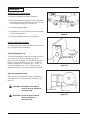
How To Prepare the Machine For Operation
Battery Maintenance
The electrical power to operate the machine comes
from the storage batteries. Storage batteries need
preventative maintenance.
WARNING:
Working with batteries can
be dangerous. Always wear
eye protection and protective
clothing when working near
batteries. NO SMOKING!
Correct Level
To maintain the batteries in good condition, follow
these instructions:
1. Keep the electrolyte at the correct level. The
correct level is between 1/4" (1/2 cm) below the
bottom of the tube in each cell and above the
tops of the plates. Check the level of the electrolyte each time you charge the batteries. See
figure 10.
Figure 10
NOTE: Check the level of electrolyte prior to charging
the batteries. Be sure the plates in each cell are
covered with electrolyte before charging. Do not top
off the cells prior to charging the battery. Electrolyte
expands during charging. As a result, the electrolyte
could overflow from the cells. Always top off the cells
with distilled water after charging.
CAUTION: Irreversible damage will occur to
the batteries if electrolyte does
not cover the plates. Keep the
electrolyte at the correct level.
CAUTION: Machine damage and discharge
across the tops of the batteries
can occur if the batteries are over
filled. Do not fill the batteries up
to the bottom of the tube in each
cell. Wipe any acid from the
machine or the tops of the batteries. Never add acid to a battery
after installation.
CAUTION: Batteries must be refilled with
distilled water only. Do not use
tap water as it may contain
contaminants that will damage
batteries.
2. Keep the tops of the batteries clean and dry.
Keep the terminals and connectors clean. To
clean the top of the batteries, use a damp cloth
with a weak solution of ammonia or bicarbonate
of soda solution. To clean the terminals and
connectors, use a terminal and connector
cleaning tool. Do not allow ammonia or bicarbonate of soda to get into batteries.
Clarke® Operator's Manual - Encore S30/L30
Figure 11
3.
Keep the batteries charged.
4.
To drain battery compartment: (See figure 11)
a. Always wear protective eye protection and
protective clothing.
b. Add a weak solution of ammonia or bicarbonate of soda solution to battery compartment to
neutralize any spilled acid.
c. Pull drain hose out from under transaxle.
d. Place hand behind flange and open valve.
e. When empty, close valve.
f. Replace valve and drain hose on top of
transaxle.
g. Neutralize any acid spills with ammonia or
bicarbonate of soda.
Page -13-
How To Prepare the Machine For Operation
How To Charge The Batteries
WARNING: Charging the batteries in an area
without adequate ventilation could
result in an explosion. To prevent
an explosion, charge the batteries
only in an area with good
ventilation.
WARNING: Lead acid batteries generate gases
which could explode. Keep sparks
and flames away from batteries. NO
SMOKING!
WARNING: Failure to disconnect the AC plug
from the wall receptacle before
connecting or disconnecting the DC
connector on the charger could
result in an explosion. Always
disconnect the AC plug from the
wall receptacle before connecting
or disconnecting the DC connector
on the charger.
Figure 12
("S" Model)
To charge the batteries, follow this procedure:
1. Put the charger on a flat surface. Make sure the
vents on the sides are at least two inches away
from walls and other objects. Make sure there are
no objects near the vents on the bottom of the
charger.
2. "L" Model - when key is off, brake is activated.
Make sure key is off.
"S" Model - Set the parking brake (if provided) by
putting it into the down position. See figure 12.
Make sure the key switch is in "OFF" position.
Figure 13A
3. Before charging the batteries the battery
compartment needs to be vented. To vent
compartment, tip up the recovery tank until it locks
in either of the two open positions. See figure 13A.
To close the tank, pull up on the latch arm and then
slowly lower the tank to the closed position.
CAUTION: Before raising tank, be sure tank is
empty.
NOTE: There is an intermediate position available
for holding the recovery tank open for charging
batteries. See figure 13B.
WARNING: Do not operate or perform
maintenance on the machine while
the recovery tank is in the
intermediate position. The tank can
be accidentally bumped and it may
slam shut.
To place the tank in the intermediate position, pull up
on the latch arm while raising the recovery tank until it
slips into the knotch area of arm. While pulling up on
the latch arm,carefully lower the recovery tank making
sure it is securely locked into place. See figure 13B. To
release the latch arm, tip the recovery tank up slightly
while pushing down on the latch arm and then slowly
lower the tank.
Page
-14-
Figure 13B
Clarke® Operator's Manual -Encore S30/L30
How To Prepare the Machine For Operation
4. Disconnect the battery pack connector from the control
housing connector. See figure 14A.
5. Connect the DC connector on the charger to the battery
pack connector. See figure 14B.
6. Connect the charger to a properly grounded single phase
(3-wire) wall receptacle having the input voltage, frequency, and ampere capacity specified on the nameplate
of the charger.
For more information on the use of the charger, read
the instructions supplied with the charger.
Figure 14A
How To Adjust Brush Cleaning Path from 24" to 26"
1. Insure brush head is in up position.
2. Turn the key switch "OFF" and remove the key.
3. Open front cover.
4. Raise plunger pin and rotate brush head. See figure 15.
5. Insure plunger pin is engaged in brush plate.
6. Close front cover.
How To Install The Brushes Or Pad Drivers
To install the brushes or pad drivers on the machine,
follow this procedure:
1. Turn the key switch "ON".
Figure 14B
2. Raise the brush head by pressing and holding the brush
switch until brush head is in its full up position.
3. Turn the key switch "OFF" and remove the key.
4. Go to the front of the machine and unlatch front cover, swing
cover open.
5. Unlatch right and left brush housings and remove them. See
figure 16.
6. Put a brush or pad driver under the brush motor plate. See
figure 17.
7.
Figure 15
("L" Model) Align the lugs on the motor gimbal with the slots
in the brush gimbal.
("S" Model) Align the lugs on the motor with the slots on the
brush gimbal.
8. ("L" Model) Pull the brush up until the gimbal locks.
("S" Model) Pull the brush up and rotate counter direction to
scrub rotation, until lugs lock.
9.
Figure 16
Repeat steps 6, 7, and 8 to install the second brush or pad
driver.
10. Reinstall right and left brush housings and latch front cover.
DANGER: Operating a machine that is not completely
or fully assembled could result in injury or
property damage. Do not operate this
machine unless it is completely
assembled. Inspect the machine carefully
before operation.
Clarke® Operator's Manual - Encore S30/L30
Figure 17
Page -15-
How To Prepare the Machine For Operation
How To Remove The Brushes Or Pad Drivers
To remove the brushes or pad drivers from the machine,
follow this procedure:
1. Turn the key switch "ON".
2. Raise the brush head by pressing and holding the brush
switch until brush head is in its full up position.
3. Turn the key switch "OFF" and remove the key.
4. Go to the front of the machine and unlatch front cover.
Swing cover open and unlatch the brush housings.
5. ("L" Model) Push down on two sides of the brush or pad
driver until the gimbals release.
("S" Model) Rotate brush same direction to scrub
rotation with a quick snapping action until brush releases.
Figure 18
6. Reinstall right and left brush housing and latch front
cover.
DANGER: Operating a machine that is not
completely or fully assembled could
result in injury or property damage.
Do not operate this machine unless it
is completely assembled. Inspect the
machine carefully before operation.
How To Operate The Machine
How To Operate The Squeegee
The squeegee wipes the floor while the vacuum motor
removes the dirty solution from the floor. Use your hand
to lower or raise the squeegee handle. To operate the
squeegee, follow this procedure:
Figure 19
1. To lower the squeegee and start the vacuum motor,
move the squeegee lever to the right and down. See
figure 18.
2. To raise the squeegee, lift the squeegee lever up.
See figure 19.
NOTE: The center position lets the vacuum motor
continue to run with the squeegee off the floor to avoid
drips and also allows you to back up the machine.
Figure 20A
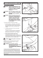
How To Fill The Solution Tank
The solution tank can be filled in the front or through the
clear drain hose at the rear of the machine (See figure
20). To fill the solution tank follow this procedure:
1. Add a cleaning chemical to the solution tank. For
the correct amount of chemical, follow the directions shown on the container.
2. Fill the solution tank with water. When filling
machine in the front with a hose, position hose
inside the fill screen as shown in figure 20A.
Page
-16-
Figure 20
Clarke® Operator's Manual -Encore S30/L30
How To Operate The Machine
When filling machine from the rear, position clear drain
hose against bracket and insert hose as shown in
figure 20B Solution level can be viewed from the back
of the machine.
WARNING: Water solutions or cleaning materials
used with this type of machine can
leave wet areas on the floor surface.
These areas can cause a dangerous
condition for the operator or other
persons. Always put CAUTION signs
near the area you are cleaning.
WARNING: Machines can ignite flammable
materials and vapors. Do not use with
or near flammables such as gasoline,
grain dust, solvents and thinners.
Only use a cleaning concentration
recommended by the chemical
manufacturer.
Figure 20B
WARNING: Clarke recommends a maximum water
temperature of 120oF (49oC).
Operating The Machine
NOTE: Put the machine in the lowest traverse speed
setting. Use the machine in an area that has no furniture or
objects until you can do the following:
B
C
A
A
1. Move the machine in a straight direction, forward and
backward.
2. Stop the machine safely.
3. Turn the machine both left and right and return to a straight
direction.
To move the machine, follow this procedure:
1. Release the parking brake (if equipped with
machine).
Figure 21
2. Turn the key switch to the "ON" position
3. Raise the brush to the highest setting.
4. Raise the squeegee.
5. When either the left or right forward/reverse switches
(figure 21, item A) are pushed in, the machine will go
forward.
6. Control the speed of traverse by using the traverse speed
control knob (figure 21, Item C).
7. To stop, release the forward/reverse switch.
8. To reverse the machine, push in the white reverse switch
(figure 21 item B) and either the right or left forward/
reverse switch (figure 21 item A) at the same time.
9.
To stop, release the forward/reverse switch.
10. To turn the machine, push the rear of the machine to the
side.
11. When you stop the machine, turn the key switch "OFF",
remove the key and set the parking brake (if equipped).
Clarke® Operator's Manual - Encore S30/L30
Page -17-
How To Operate The Machine (cont)
How To Clean A Floor
WARNING:
Water solutions or cleaning materials used
with this type of machine can leave wet areas
on the floor surfaces. These areas can cause
a dangerous condition for the operator or
other persons. Always put CAUTION signs
near the area you are cleaning.
To clean a floor follow this procedure:
1. Set the parking brake (if equipped with machine.)
2. Put the water and a cleaning chemical in the clean solution
tank.
3. Release the parking brake (if equipped with machine.)
4. Turn the key switch "ON".
5. Lower the squeegee.
6. Activate the brush switch until correct pressure is achieved.
WARNING:
This machine is capable of maximum head
pressure with worn pads or brushes. With
this feature, there is the possibility of
exceeding the recommended brush pressure
on new pads or brushes. This will either
create reoccurring circuit breaker tripping or
the possibility of lost traction and control. The
brush switch should be activated to
accomplish only enough brush pressure for
the job. This will allow longer battery life and
cleaning time.
NOTE: Keep the machine moving when the brush is
rotating on the floor. Pre-wet brush/pad or keep light
pressure on brush until solution flow is adequate to keep
brush/pad from scratching the floor.
To pre-wet brushes you should first turn the speed knob to the
lowest setting on the "L" model. Then on both the "S" and "L"
models, lower brushes until brushes are just touching the floor.
Activate the forward/reverse switch to start motor and solution
flow.
7. Turn the solution knob to the right to activate the flow of
solution. Adjust the flow of clean solution to the flow
desired.
8. Move the machine across the floor in the forward direction.
9. Make a 180° turn.
NOTE: When you make more passes across the floor, let the
brush clean approximately 2 inches (5 cm) of the area already
cleaned by the brush.
NOTE: During most cleaning procedures, apply and remove the
solution in one operation.
How To Clean A Very Dirty Floor
To clean a very dirty floor, follow this procedure:
1. Apply solution to the floor.
2.
Do not lower the squeegee. This will keep the vacuum
motor off.
3.
Lower the brush or pad and scrub the floor.
4.
Scrub the floor again with additional solution and lower the
squeegee.
5.
Pick up all the solution with the squeegee.
Page
-18-
Clarke® Operator's Manual -Encore S30/L30
Maintenance
WARNING: Maintenance and repairs must be
done by authorized personnel only.
WARNING: Always empty the solution tank and
recovery tank before doing any
maintenance.
WARNING: Keep all fasteners tight.
These Maintenance Procedures Must Be Done
Every Day
Keep the machine clean, it will need fewer repairs and
have longer life.
Figure 22
Do These Procedures When You Begin Your Work
Period
1. Turn off key switch.
A
2. Disconnect AC power from battery charger (follow charger instructions).
2. Disconnect the plug on the battery charger from
the battery pack connector.
3. Join the connector from the batteries to the
control panel cable connection. See figure 22.
4. Make sure the Screen filter over the vacuum
motor is clean and in position. See figure 24.
5. Make sure the recovery tank lid is on correctly.
See figure 23, Item A.
Figure 23
6. Make sure the valve on the recovery drain hose is
clean. Tightly close the valve.
7. Make sure the brushes/pads are in position and
installed correctly.
8. Make sure brush housings and skirts are in
position on the brush head.
9. Check the installation of the squeegee and
squeegee hose.
10. Make sure the solution drain / level indicator hose
is secure on the storage mount on the rear of the
machine.
Figure 24
Clarke® Operator's Manual - Encore S30/L30
Page -19-
Maintenance
Do These Procedures When You End Your Work
1. Drain the solution tank (Figure 25) and the recovery
tank (Figure 26). To drain the tanks , follow this
procedure:
a. Turn the key switch “OFF”.
b. Remove the drain hose from the back of the
machine.
c. Put the end of the hose over a drain or bucket.
Figure 25
d. Recovery Tank:
1.) Turn the valve handle to the left. Pull the
handle out to open the drain (Figure 27).
NOTE: Have the opening in the side of the valve away
from you when you open the valve.
2.) To open the valve completely, turn the
handle to the right. Pull the handle out of
valve (Figure 28).
Solution Tank:
When hose is lowered to water level, water will
flow.
2. Flush the tanks. To flush the tanks, put clean water in
the tank through the opening on top of the tank.
Figure 26
3. If a tank or drain hose has an obstruction, use a pressure
water hose to flush the tank or hose. Put the water hose
into the drain hose.
4. Leave the tanks and the recovery drain valve open to dry
in the air.
5. Check the squeegee blade. Use a cloth to clean the
squeegee blade. If the squeegee blade is damaged or
worn, turn or replace the blade.
6. Check and clean the solution lid gasket. Use a mild
cleaning solution and rinse the parts in clean water.
Check the batteries and if necessary add distilled water
after charging. The correct level is within 1/4 inch (1/2 cm)
of the bottom of the tube in each cell.
Figure 27
CAUTION: Tap water may contain contaminants that will damage batteries.
Batteries must be refilled with
DISTILLED WATER ONLY.
WARNING: Lead acid batteries generate
gases which can cause an explosion. NO SMOKING. Always wear
eye protection and protective
clothing when working near
batteries.
Use a clean cloth and wipe the surface of the machine.
Figure 28
Charge the batteries. See the instruction in the section of
this book called “How To Charge The Batteries”.
Page
-20-
Clarke® Operator's Manual -Encore S30/L30
Maintenance
Maintenance Procedures To Be Done Every Week:
WARNING: Maintenance and repairs must be done
by authorized personnel only. Always
empty the solution tank and the
recovery tank before doing any
maintenance. Keep all fasteners tight.
WARNING:
Always wear eye protection and
protective clothing when working near
batteries. Do not put tools or other
metal objects across the battery
terminals or the tops of the batteries.
CAUTION: To prevent damage to the machine, and
discharge across the tops of the
batteries, do not fill the batteries above
the bottom of the tube in each cell.
Wipe any acid from the machine or the
tops of the batteries. Do not add acid to
battery after installation.
Figure 29A
NOTE: Always turn off key switch before servicing the
machine.
WARNING: Always wear eye protection and
protective clothing when working near
batteries. NO SMOKING!
1. To inspect batteries, tip up recovery tank until it locks in
the full open position. See figure 29A. To close the tank,
pull up on the latch arm and then slowly lower the tank to
the closed position.
CAUTION: Before raising the tank, be sure tank is
empty.
NOTE: There is an intermediate position available for holding
the recovery tank open for charging batteries. See figure 29B.
WARNING: Do not operate or perform
maintenance on the machine while
the recovery tank is in the
intermediate position. The tank can
be accidentally bumped and it may
slam shut.
Figure 29B
2. Disconnect the batteries. Use a cloth and a solution of
ammonia or bicarbonate of soda to wipe the top of the
batteries. Clean the battery terminals. Reconnect the
batteries.
3. Check the hoses for leaks, obstructions and other
damage.
4. Check and clean the filter screen in the solution hose. To
clean the screen, follow this procedure:
a.
b.
c.
d.
Close the solution flow valve.
Turn the connector to the left.
Remove and clean the filter screen.
Install the filter screen in the valve connector.
Turn the connector to the right to connect the
hose. See figure 34
e. Open the solution flow valve. See figure 34.
Figure 30
5. Use a grease gun to lubricate the dual casters. See figure
30.
Clarke® Operator's Manual - Encore S30/L30
Page -21-
Maintenance
Maintenance For The Squeegee
To remove the squeegee, follow this procedure:
1. Remove the squeegee assembly by loosening the two
knobs that attach the squeegee to the machine. Pull
the squeegee assembly off. See figure 31.
2. Inspect the squeegee blade.
3. If the blade is worn, turn the blade so that a new edge
is in the wiping position.
Figure 31
4. Reinstall squeegee assembly on the machine.
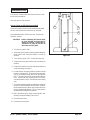
How To Adjust The Squeegee
The following adjustments are set at the factory, however
they may require slight adjustment.
Adjusting Squeegee Tilt:
The tilt of the squeegee causes the rear blade to raise up
in the center or on the ends, depending on which
direction the tilt is changed. For tilt adjustment, refer to
figure 32. Loosen left and right screw "X". In order to
bring the blades down in the center, tip "Y" down. To
bring both ends down, tip "Y" up. Make very small
adjustments and try it until a uniform flare is achieved.
Figure 32
Adjusting Squeegee Blades:
When properly installed the front blade should be approximately 0.06" (1.5mm) above the rear blade. See
figure 33.
WARNING: Maintenance and repairs
must be done by authorized
personnel only .
REAR BLADE
0.06 (1.5 mm)
Figure 33
WARNING: Electrical repairs must be
done by authorized
personnel only.
Page
-22-
Clarke® Operator's Manual -Encore S30/L30
Maintenance cont.
Consult your Clarke Authorized Service Person to do
the service procedures.
Use only genuine Clarke parts.
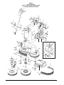
How to Center or Offset the Brush Head
1
2
The brush head on the Encore 30 should be adjusted
as far to the left side of the machine as possible.
3
Recommended tools: 3/8" drive rachet, 3" extension
and 9/16" socket.
CAUTION:
Before offsetting the brush head,
be sure that the recovery tank is
empty of solution. Follow the instructions on page 20 on how to
drain the recovery tank.
4
1. Turn the key switch "ON".
2. Raise the brush head by pressing and holding the
brush switch until the brush head is in its full up
position.
Figure 34
3. Turn the key switch "OFF" and remove the key.
4. Tip up the recovery tank until it locks in the full open
position.
5. Go to the front of the machine and unlatch the front
cover and swing cover open.
6. Locate the four mounting studs on the brush head
bracket. See figure 34. The top two mounting nuts
can be accessed through the top of the solution
tank. The lower two can be accessed through the
front. Loosen the four mounting nuts 2 to 3 turns
counterclockwise. NOTE: Do not remove mounting
nuts.
7. The brush head assembly can slide to the right side
by one inch or placed back into the center. Slide the
brush head assembly all the way to the ends of the
slots for the desired position. This insures that the
head operates straight up and down.
8. After repositioning the brush head, tighten nuts
securely to approximately 236 inch-lbs.
9. Close the front cover.
10. Close the recovery tank.
Clarke® Operator's Manual - Encore S30/L30
Page -23-
Clarke®
Encore S30 and L30
Accessories - 2/04
ACCESSORIES
Description
Power Wand System Kit
Clarke Care Kit
39" Squeegee Assembly
Poly Dur Protectant
Kit, Grease Gun
Kit, Low Voltage Shut-Off
Brake Kit Assembly "L"
Brake Kit Assembly "S"
Accessory Bag
Hour Meter Kit
Soft Caster Assembly
Gimbal, Brush "L"
Gimbal, Brush Spring "L"
Dual Direct Clutch Plate "S"
Spacer for 30034A Clutch Plate "S"
Center Lock Pad Retainer
Kit, Solution Fill
Brushes and Pad Assemblies:
Size
Description
15"
15"
15"
15"
15"
Polyproplene
Pad Driver Asm.
Grit-Lite
Clean Grit
Nylon Soft
Squeegee Blades:
Description
Blade, Rear - Gum Rubber
Blade, Rear - Nitrile Solid
Blade, Rear - Ribbed Orange
Blade, Front - Ribbed Natural
Blade, Front - Slit Grout
Blade, Front - Ribbed Orange
Page
-24-
Part No.
Part No.
(Gimbal "L") (Clutch "S")
30394A
30470A
30393A
30398A
30396A
30317A
30397A
30464A
30395A
30399A
Part No.
10150A
14607A
10068A
50478A
55420A
14097A
10072A
10073A
30070A
10656A
51092A
833802
838301
30034A
10143A
56941A
10177A
Used For
General Scrubbing Hard Floors
Use for Pads
39" Assembly
30069A
30082A
30086A
30091A
30080A
30084A
Clarke® Operator's Manual -Encore S30/L30
ENCORE
S30 and L30
Section II
Parts and Service Manual
(70762A)
U.S. Patent No. 6,105,192; No. 6,557,207; No. 6,760,947
Clarke® Operator's Manual - Encore S30/L30
Page -25-
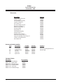
HOW TO CORRECT PROBLEMS IN THE MACHINE
PROBLEM
There is no solution flow.
The solution flow does not stop.
The machine does not remove all the
water from the floor.
The batteries do not give the normal
running time.
Page
-26-
CAUSE
ACTION
The solution tank is empty.
Fill the solution tank.
The solution valve is closed.
Open the solution valve.
There is an obstruction in the solution hose
or filter.
Remove the obstruction from the hose or filter.
The solution valve or electric wiring is
damaged.
Repair or replace the valve or the electric
wiring.
The solution module is defective.
Replace solution module
The solution valve is open.
Close or Clean the solution valve.
The solution valve or wiring is damaged.
Repair or replace the valve and the wiring.
The solution valve is dirty
Clean the solution valve.
There is a damaged seat and washer in the
solution valve.
Replace the seat and washer.
The solution module is defective.
Replace solution module.
The squeegee is up.
Lower the squeegee.
The squeegee tilt is not correct.
To adjust See Figure 11, page 22.
The recovery tank is full.
Drain the recovery tank.
The screen filter is dirty.
Clean the screen filter.
There is an obstruction or damage in the
squeegee, squeegee hose or standpipe.
Remove the obstruction or repair the damage.
The vacuum motor is not running.
Check for tripped breaker. Have an authorized
service person make repairs.
The squeegee hose is disconnected, or
damaged
Check and connect hose.
The squeegee blade is damaged, worn, or
incorrectly installed.
Turn or replace the squeegee blade.
Correctly install the squeegee blade.
The gaskets on the cover of the recovery
tank are damaged.
Replace the gaskets.
The battery terminals are dirty or damaged.
Clean the terminals and connectors. Replace
the damaged cables. Charge the batteries.
The electrolyte level is too low.
Add distilled water to each cell and charge the
batteries.
The batteries are not fully charged.
Charge the batteries for a full 16 hour charge.
The charger is damaged.
Have an authorized service person repair the
charger.
The battery is defective.
Check voltage of each cell while discharging.
The batteries are disconnected.
Connect the batteries.
Brush is in heavy scrub setting.
Adjust Pressure.
Clarke® Operator's Manual -Encore S30/L30
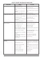
PROBLEM
The cleaning is not even.
CAUSE
ACTION
The scrub brush or pad is worn.
Replace the scrub brush or pad.
There is damage to the brush assembly,
caster or the solution valve.
Have an authorized service person make
the needed repairs.
The brush motor is not running
Check for tripped breaker. Reset. Check
for loose connections.
The solution level is low.
Fill the solution tank.
NOTE: If the problem continues consult an
authorized service person.
The machine does not run.
The machine loses power.
Reset the circuit breaker.
Key or switch is off.
Turn key or switch on.
Batteries are unplugged.
Battery terminals are dirty.
Check the battery connections.
Batteries are discharged
Check battery gauge and recharge
NOTE: If the problem continues consult an
authorized service person.
Clarke® Operator's Manual - Encore S30/L30
Page -27-
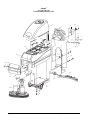
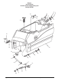
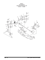
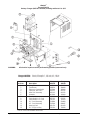
Clarke®
Encore S30/ L30
Final Assembly Drawing 2/07
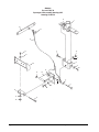
1
3
2
33
4
5
6
31
28
27
26
30
27
32
7
29
15 4
25
9
8
24
8
10
11
23 22
20
19
8
10
11
8
9
21
12
18
17
13
14
16
8
10
11
Page
-28-
Clarke® Operator's Manual -Encore S30/L30
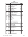
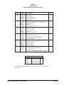
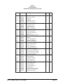
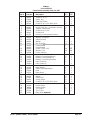
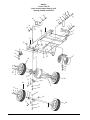
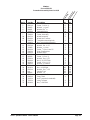
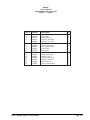
Clarke®
Encore S30/L30
Final Assembly Parts List 2/07
Ref. #
1
2
Part No.
Description
See pg 30
Assembly, Recovery Tank
See pg 36
Assembly, Control Panel “L”
See pg 36
Assembly, Control Panel “S”
3
30064A
Rear Cover
4
80108A
Screw, 10-24 x ½ SS
5
70080A
Plate, Warning
6
83010A
Rivet, Pop 1/8
7
See pg 34
Assembly, Rear Panel “L”
See pg 34
Assembly, Rear Panel “S”
8
980651
Washer, 5/16 Flat
9
920110
Nut, 5/16 -18 ESNA
10
980652
Washer, 5/16 Lock
11
85811A
Screw, 5/16 -18 x ¾
12
See pg 40
Assembly, Squeegee 39”
13
See pg 38
Assembly, Squeegee Lift
14
See pg 42
Assembly, Traverse System “L”
See pg 42
Assembly, Non-Traverse System “S”
15
980982
Washer #10
16
See pg 44
Assembly, Brush Head “L”
See pg 44
Assembly, Brush Head “S”
17
81105A
Nut, 3/8-16 ESNA
18
87031A
Washer, 3/8 Flat SS
19
50965A
Hinge
20
85395A
Screw, ¼-20 x 1/2 SS
21
30249R
Front Cover
22
50966A
Latch, Front Cover
23
930090
Rivet, 5/32 x 9/16
24
See pg 32
Assembly, Solution Tank
25*
Page 12
Battery
871334
Battery 12V, 195 AH (wet - UT Post)
871335
Battery 12V, 195 AH (dry - UT Post)
40136A
Battery 6V, 250 AH (wet - Stud Post)
40137A
Battery 6V, 250 AH (dry - Stud Post)
891384
Battery, 6V 330 AH (wet - UT Post)
891385
Battery, 6V 330 AH (dry - UT Post)
26
41206A
Series Battery Cable (Taper Style)
41217A
Series Battery Cable (Ring Style)
27
980205
Washer, 5/16 Fender
28
85734A
Screw, 5/16-18 x 2
29
85739A
Screw, 5/16-18 x 3 Hex
30
87026A
Washer, ¼ flat SS
31
41211A
Battery, Cable (Taper Style)
40174A
Battery, Cable (Ring Style)
32
85518A
Screw, ¼-20 x 3/4
33
54436A
Plug, Hole 13/8
NI
10132A
Lit Kit
NI
17531A
Pad Driver Assembly
10140A
Pad Driver Assembly
NI
40512A
Battery charger
NI
77092A
Label, Gases
NI
77093A
Label, Falling
NI
70226A
Label, Battery
NI
30070A
Accessory Bag
NI
10072A
Parking Brake Assembly "L"
NI
10073A
Parking Brake Assembly "S"
* See page 12 for installation.
Clarke® Operator's Manual - Encore S30/L30
Qty
“L”
Ref
Ref
1
4
1
2
Ref
11
4
7
7
Ref
Ref
Ref
2
Ref
4
4
1
6
1
Ref
2
Ref
Qty
“S”
Ref
Ref
1
4
1
2
Ref
11
4
7
7
Ref
Ref
Ref
2
Ref
4
4
1
6
1
Ref
2
Ref
4
4
4
4
3
3
4
2
2
5
1
1
5
1
1
1
1
1
1
1
1
1
-
2
2
4
4
4
4
3
3
4
2
2
5
1
1
5
1
1
1
1
1
1
1
1
1
Page -29-
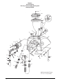
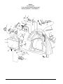
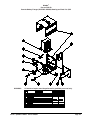
Clarke®
Encore S30/L30
Recovery Tank Assembly Drawing 6/07
Drawing #10428A
1
2
43
3
4
5
42
41
6
8A
43
7
40
8B
9
8
10
39
37, 37A
38
36
35
20
19
7
34
12
18
17
16
26
20
18
44
27
30
16
33
13
11
15
31
25
22
14
28
32
45
24 23
29
21
22
#40 Recommended Torque
175 + or - 5 inch pounds
Page
-30-
Clarke® Operator's Manual -Encore S30/L30
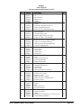
Clarke®
Encore S30/L30
Recovery Tank Assembly Parts List 6/07
Ref. #
1
2
3
4
5
6
7
8
8A
8B
9
10
11
12
13
14
15
16
17
18
19
20
21
22
23
24
25
26
27
28
29
30
31
32
33
34
35
36
37
37A
38
39
40
41
42
43
44
45
NI
NI
Part No.
962798
30057A
81110A
30065A
58069A
39338A
837304
10660A
40002A
56459A
59877A
30248A
60373A
87622A
80043A
60336A
85100A
30068A
43402A
41809A
82100A
872010
35165A
53371A
839401
962943
52206A
962987
833901
833407
51060A
830208
80110A
752020
43401A
674110
85728A
87026A
51049A
51050A
50996A
643418
58533A
920797
962666
920296
38020A
38735A
30343A
839410
70226A
Clarke® Operator's Manual - Encore S30/L30
Description
Screw, 10-24 x .5
Lid
Nut, 10-24 SS
Gasket, Lid
Strainer
Stand Tube
O-Ring
Switch Kit, (Includes 8A, 8B, 9)
Switch (included in Item 8)
Relief, Strain (included in Item 8A)
Seal, Washer
Tank, Recovery
Latch, Recovery Tank
Washer, Nylon 5/16 x 5/8 x 1/32
Screw, .25 x 20 x .25, Shoulder
Strap, Hose Retainer
Screw, 10-32 x ½ SS Xylan Coating
Hinge, Pin (included w/ item 10)
Housing, Connector(included in 8A)
Contact (included in 8A)
Nut, Strain Relief Lock
Clamp, Hose
Hose, Drain
Clamp, Hose
Valve, Drain
Screw, 8-18 x ½ PN
Chain
Screw, 10-24 x 3/8 Pan
Drain, Valve Handle
Gasket, Drain Valve
Hose, Squeegee
Squeegee Stand Tube
Hose Clamp
Hose Clamp
Housing, Vac Motor Connector
Hose
Screw, ¼-20 x 4 Hex
Washer, ¼ Flat
Motor, Vacuum (3-Stage)
Motor, Vacuum, (2-Stage Option)
Brushes, Carbon
Gasket
Spacer
Nut
Screw, 10-24 x ¾
Nut, 10-24 Elastic
Strap
Connector, Muffler
Muffler
Valve Asm. (includes 23, 24, 25, 26, 27, 28)
Label, Battery Installation
Qty
1
1
1
1
1
1
2
1
1
1
1
1
1
1
1
1
2
2
2
4
1
2
1
2
1
1
1
1
1
1
1
1
1
1
2
1
3
3
1
1
2
1
3
1
1
1
1
1
1
1
1
Page -31-
Clarke®
Encore S30/L30
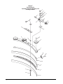
Solution Tank Assembly Drawing 7/04
Drawing #10584A
25
19
24
21
20
23
2
18
1
15
17
16
3
15
12
10
26
4
5
6
7
5
5
9
11
13
5
8
14
Page
-32-
5
5
Clarke® Operator's Manual -Encore S30/L30
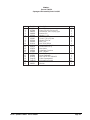
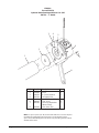
Clarke®
Encore S30/L30
Solution Tank Assembly Parts List 1/08
Ref. #
1
2
3
4
5
6
7
8
9
10
11
12
13
14
15
16
17
18
19
20
21
23
24
25
26
NI
NI
Part No.
872010
50964A
30244A
59614A
722030
30453A
820207
30412A
51526A
80254A
30446A
51204A
59789A
38014A
81109A
50966A
80105A
50963B
51308B
69879A
170892
170915
60480A
51346A
80108A
53562A
30162A
10177A
Description
Clamp, Hose
Hose, Drain
Tank, Solution
Valve, Battery Drain
Clamp, Hose
Hose, Clear Vinyl
Adapter, Hose 3/8 MPT x ½ Hosebarb
Hose, Stretch
Elbow
Screw, 8-32 x 1 SS
Hose 8"
Valve, Solution
Valve, Solution
Splitter
Nut, 8-32 ESNA SS
Latch
Screw, 8-32 x 1¼ SS
Screen, Fill (with hose retention)
Strainer (without hose retention)
Bracket, Latch
Washer, Lock ¼
Screw, ¼-20 x ¾ SS Hex
Bracket, Hose
Spring, Hose
Screw, 10-24 x ½
Filter, Bowl Asm.
Funnel (included w/Kit 10177A)
Kit, Solution Fill
Qty
1
1
1
1
6
1
1
1
1
1
1
1
1
1
2
1
1
1
1
1
2
2
1
1
2
1
1
1
(includes #18-51308A)(includes NI - 30162A)
53562A Components
Clarke P/N
Description
50018A
Bowl, Filter
53563A
Filter, Screen
53564A
Upper Body
54369A
Gasket, Bowl
Qty.
1
1
1
1
NOTE:
indicates a change has been made since the last publication of
this manual.
Clarke® Operator's Manual - Encore S30/L30
Page -33-
Clarke®
Encore S30/L30
Rear Panel Assembly Drawing 9/03
Drawing #10064A (L)
Drawing #10067A (S)
1
2
1 2
36
5
4
3
34
35
6
7
34
32
33
8
9
9
10
31
10
9
10
6
29
28
3
11
27
3
10
15
30
11
16 17
16 15
37
26
25
24
18
14
21
20
19
13
2
22
12
23
Page
-34-
Clarke® Operator's Manual -Encore S30/L30
Clarke®
Encore S30/L30
Rear Panel Assembly Parts List 9/03
Ref. #
Part No.
Description
1
2
3
4
5
920224
980603
920056
46106A
40133A
40134A
962212
85383A
41810A
85395A
980614
85391A
60261A
60257A
920346
80028A
980692
438360
64901A
64490A
980666
85389A
68643A
962968
61260A
47388A
85601A
81217A
60264A
41146A
193951
41811A
41810A
40157A
40169A
962798
40132A
14097A
30097A
77093A
77092A
47809A
911933
40519A
Nut, 10-32
Washer, Starlock
Nut, 6-32
Rectifier
Harness, Power “L”
Harness, Power “S”
Screw, 6-32 x 7/8
Screw, 10-32 x ¾
Solenoid, Brush
Screw, ¼-20 x ½
Washer, Starlock, ¼
Screw, ¼-20 x 5/8
Panel, Rear Metal
Cable, Squeegee Lift
Nut, Pal
Bolt, Shoulder, 5/16 x 1.0
Washer, Flat 5/16 SS
Spring
Lever, Squeegee Lift
Handle, Squeegee
Washer, 3/8 Starlock
Screw, 3/8-16 x 5/8
Plate, Vacuum Wear
Screw, 10-24 x ½
Plate, Squeegee Lift
Switch, Vacuum Lever
Screw, 6-32 x 1¼ PN
Nut, ¼-20 x .218H Nylock
Bracket, Power Connector
Cable, Assembly Console
Grommet, slotted, 8”
Solenoid, Main
Solenoid, Main
Harness, Traverse
Solenoid, Vacuum
Screw, 10-24 x ½
Control, Traverse
Low voltage Shutoff
Insulator, Mylar
Label, Falling Parts
Label, Gases
3/8 Ring Terminal, 14-16
#10 Ring Terminal, 14-16
Ring Terminal, 5/16
6
7
8
9
10
11
12
13
14
15
16
17
18
19
20
21
22
23
24
25
26
27
28
29
30
31
32
33
34
35
36
37
NI
NI
NI
NI
NI
Clarke® Operator's Manual - Encore S30/L30
Qty
L
2
4
5
1
1
3
1
1
6
10
4
1
1
1
1
2
1
1
1
1
1
1
2
1
1
2
1
1
1
Ref
1
1
1
4
1
1
1
1
-
Qty
S
2
4
1
2
1
6
10
4
1
1
1
1
2
1
1
1
1
1
1
2
1
1
2
1
1
1
Ref
1
1
2
1
1
1
1
1
1
1
Page -35-
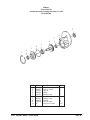
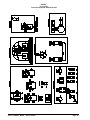
Clarke®
Encore S30/L30
Control Panel Assembly Drawing 9/07
Drawing #10065A "L" and 10066A "S"
1
2
4
7
3
37
5
11 12
8
6
35
27
38
11
10
14
28
29
7
30
40
32 31
34
19
27
18
1516
15 16
30
26
16
25
39 16
15
17
15
2
5
5
24
23
20
9
22
21
Page
-36-
Clarke® Operator's Manual -Encore S30/L30
3
Clarke®
Encore S30/L30
Control Panel Assembly Parts List 9/07
Ref. #
1
2
3
4
5
6
7
8
9
10
11
12
13
14
15
16
17
18
19
20
21
22
23
24
25
26
27
28
29
30
31
32
34
35
37
38
39
40
NI
NI
NI
Part No.
55413A
84237A
47380A
60334A
80108A
87052A
962262
50962A
85703A
962957
40135A
60259A
980666
40158A
980603
920224
30062A
30072A
85391A
87026A
44308B
41422A
41433A
41448A
41423A
70649A
70648A
60258A
40217B
40168A
55502A
51057A
962330
980608
11131A
50961A
80104A
70219A
34264A
30096A
47708A
47712A
912226
Description
Key (included w/Item 3)
Screw, 10-32 x ½
Switch, Key
Panel, Key Switch
Screw, 10-24 x ½ SS Black Xylan
Washer, Switch
Screw, Set 8-32 x ½ (included in item 29)
Traverse, Control Knob
Screw, 10-00 x ½ PN
Screw, 10-16
Harness, Potentiometer Assembly.
Bracket, Traverse Switch
Washer, 3/8 Starlock
Switch, Reverse
Washer
Nut, 10-32 Hex
Control Handle
Control Handle
Screw, ¼-20 x 1/2 SS
Washer, ¼ SS
Control, Solution
Breaker, Circuit 25 Amp Traverse
Breaker, Circuit 40 Amp Brush
Breaker, Circuit 30 Amp Vac
Breaker, Circuit 5 Amp Actuator
Label, Control “L”
Label, control “S”
Panel, Control, Metal
Meter, Battery
Switch, Brush Adjustment
Knob
Meter, Brush
Screw, 6-32 x 3/8
Washer
Switch Asm.
Spring, Switch
Screw, 10-32 x ½ SS Black Xylan
Label, Key Switch
Gasket, Panel
Gasket, Switch
¼ F.I.M.Q.D.
¼ F.I.F.Q.D.
Meter, Hour (Optional)
Clarke® Operator's Manual - Encore S30/L30
Qty
“L”
Ref
2
1
1
8
1
4
1
1
2
1
1
1
1
4
4
1
Ref
Ref
1
1
2
1
1
1
1
1
1
1
1
4
4
2
4
4
1
1
1
4
1
Qty
“S”
Ref
2
1
1
8
1
2
1
2
2
1
Ref
Ref
1
2
1
1
1
1
1
1
1
1
4
4
2
4
4
1
1
1
2
0
Page -37-
Clarke®
Encore S30/L30
Squeegee Lift Assembly Drawing 9/03
Drawing # 10075A
15
1
20
21
19
6
12
10
22
3
4
17
5
6
15
15
16
8
9
7
8
2
14
13
11
18
Page
-38-
Clarke® Operator's Manual -Encore S30/L30
Clarke®
Encore S30/L30
Squeegee Lift Assembly Parts List 9/03
Ref. #
1
2
3
4
5
6
7
8
9
10
11
12
13
14
15
16
17
18
19
20
21
22
Part No.
61263A
85730A
980638
69860B
87026A
170915
962481
87031A
920208
81111A
80101A
85811A
67867A
60256A
81104A
60255A
60328A
81112A
Page 35
Page 35
920346
980651
Clarke® Operator's Manual - Encore S30/L30
Description
Bracket Tube
Screw, 3/8-16 x 1¼, Hex SS
Lockwasher, 3/8 LT Spring Type
Bracket, Pin
Washer, ¼ SS
Screw, ¼-20 x ¾
Screw, ¼-20 x 1¼ Hex
Washer, 3/8 Flat
Nut, ¼-20
Nut, 3/8-16 ESNA
Screw, ¼-20 x 3¼ SS
Screw, 5/16-18 x ¾
Nut, spacer
Squeegee, Pivot Arm
Nut, ¼ Nylock
Bracket, Squeegee
Mount, Squeegee
Nut, 5/16-18 Thin ESNA SS
Cable, Squeegee Lift
Lift Handle Assembly
Palnut
Washer
Qty
1
1
1
1
2
4
2
3
2
1
1
1
1
1
5
1
1
1
Ref
Ref
Ref
1
Page -39-
Clarke®
Encore S30/L30
Squeegee Assembly Drawing 1/08
Drawing # 10068A
1
2
21
21
5
3
19
4
5
4
18
20
21
7
17
8
9
10
11
12
13
22
14
16
15
Page
-40-
Clarke® Operator's Manual -Encore S30/L30
Clarke®
Encore S30/L30
Squeegee Assembly Parts List 1/08
Ref. #
1
2
3
4
5
6
7
8
9
10
11
12
13
14
15
16
17
18
19
20
21
22
Part No.
80253A
980657
60243A
30049B
81104A
60254A
50958A
30048A
60272A
50835A
930086
60252A
30069A
30058A
30091A
80011A
81301A
34260B
25201B
60358A
61370A
80280A
Description
Screw, ¼-20 x 1½ Hex SS
Washer, ¼ Lock
Bracket, Squeegee Wheel
Wheel, Squeegee
Nut, ¼-20
Bolt, Shoulder 5/16x 2¼
Ring, 3/8 ID Snap
Wheel, Guide, 4 Inch Diameter
Channel, Squeegee Weldment
Latch, Squeegee Clamp
Rivet, 3/16 x .450 Aluminum
Strap, Clamp, Squeegee Retainer
Blade, Rear, Gum Rubber, 39”
Spacer, Squeegee 39”
Blade, Front Ribbed 39”
Screw, 3/8-16 x 3
Nut, 3/8-16 Jam SS
Gasket
Knob
Shim, Squeegee Wheel
Weight
Nut, Squeegee Backup
Qty
4
4
2
4
2
2
2
2
1
2
1
1
1
1
2
2
1
2
2
8
2
NOTE: indicates a change has been made since the last publication of
this manual.
Clarke® Operator's Manual - Encore S30/L30
Page -41-
Clarke®
Encore S30/L30
Frame Axle Assembly Drawing 9/03
Drawing #10069A and 10070A
28
27
26
29
22
22
16
1
16
2
25
4
31
24
3
5
6
31
32
32
23
22
21
19
8A
7
22
4
3
2
19
18
30
11
8A
13
10
8B
11
17
9
13
3 16
15 14
32
32
11
13
8B
11
13
Page
-42-
9
Clarke® Operator's Manual -Encore S30/L30
Tr
av
er
se
No
nTr
av
er
se
Clarke®
Encore S30/L30
Frame Axle Assembly Parts List 9/03
Ref. #
1
2
3
4
5
6
7
8A
8B
9
10
11
12
13
14
15
16
17
18
19
21
22
23
24
25
26
27
28
29
30
31
32
Part No.
85700A
85811A
980652
980651
60328A
60260B
50968A
61437A
61436B
50967A
60266A
60289A
87031A
170883
80103A
57423A
87616A
980205
962620
87026A
80104A
85395A
980614
59789A
81105A
87031A
Ref
980205
85734A
69639A
10135A
77267A
81108A
Description
Screw, ¼-20 x 1
Screw, 5/16-18 x ¾
Washer, 5/16 Lock
Washer, flat 5/16
Squeegee Mount
Frame Assembly
Caster, Assembly
Wheel Assembly
Wheel, Non Traverse
Transaxle w/mounting hubs
Non-Traverse Axle Assembly
Mount, Transaxle
Washer, flat 3/8 SS
Washer, 3/8 Lock
Screw, 3/8-24 x 1 Hex SS
Ring, Snap Retainer
Washer, Nylon
Washer, 5/16 Fender
Screw, 5/16-24 x ¾
Washer, Flat, ¼ SS
Nut, ¼-20 SS ESNA
Screw, ¼-20 x ½ SS
Washer, ¼ Starlock
Valve Solution
Nut, 3/8-16 ESNA
Washer, Flat 3/8 SS
Solution Tank
Washer, 5/16
Screw, 3/8-16 x 2
Strap, Static
Hub, Transaxle (includes #9)
Label, Tie Down
Nut, 3/8-24 ESNA
Clarke® Operator's Manual - Encore S30/L30
Qty
1
6
6
6
Ref
1
1
2
1
2
4
4
4
2
8
9
2
5
Ref
Ref
Ref
Ref
Ref
Ref
1
Qty
6
8
6
Ref
1
1
2
1
4
4
4
2
2
2
2
2
2
Ref
Ref
Ref
Ref
Ref
Ref
-
4
4
4
4
Page -43-
Clarke®
Encore S30/L30
Brush Head Assembly Drawing 9/03
Drawing #10582A and #10583A
1
2
1
3
45
67
77
8
9
72
10
71
11
6
68
70
60
21
76
75
73
7
12
13
15
69
66
59
62
67
16
74
58
14 17
11
57
52
54
53
20
56
18
19
22
61
52
78
31
15
23
21
30
51
24
29
50
25
49
40
55
28
48
46
45
44
33
31
43
41
38
42
26
27
32
37
47
40
41
40
39
34
38
37
36
35
Page
-44-
Clarke® Operator's Manual -Encore S30/L30
Clarke®
Encore S30/L30
Brush Head Assembly Parts List 1/08
Drawing #10582A and #10583A
Ref. #
1
2
3
4
5
6
7
8
9
10
11
12
13
14
15
16
17
18
19
20
21
22
23
24
25
26
27
28
29
30
31
32
33
34
35
36
37
38
Part No.
38708A
50950B
60265A
47374A
47422B
980608
962980
60251A
82501A
60236A
766780
85838A
980673
63058A
67705B
920278
980626
80100A
80091A
60483A
81217A
60335A
170915
782002
81104A
34705A
722030
962989
38014A
61372A
962992
55721A
30391A
38243A
85616A
82004A
81109A
60337A
Description
Washer, Spacer Nylon
Actuator
Plate, Nut
Switch, Lever
Switch, Whisker
Washer, #6
Screw, 6-32 x 1
Mount, Switch
Pin
Bracket, Brush Head
Pin, Hair
Screw, ½ x 20 x 1½
Washer
Bar, Linkage
Bearing, Sleeve
Nut, ½-20 SS
Washer, ½ Lock
Screw, ½-20 x 1 Hex Head
Pin, Brush Lift
Mount, Brush Head
Nut, ¼-20 ESNA .218 Height
Bracket, Brush Housing
Screw, ¼-20 x ¾ SS
Clamp, Hose
Nut, ¼-20 ESNA
Hose, Solution
Clamp, Hose
Screw, ¼-20 x 1½
Solution Splitter
Plate, Brush Head
Screw, 8-32 x 5/8 SS
Latch, Brush Housing
Housing, Left Brush
Skirt, Left
Screw, 10-32 x 5/8 SS
Nut, “T” 10-32
Nut, 8-32 SS ESNA
Plate, Latch Brush
Qty Qty
L
S
2
2
1
1
2
2
1
1
1
1
4
4
4
4
1
1
1
1
1
1
5
5
4
4
4* 4*
4
4
8
8
8
8
4
4
4
4
1
1
1
1
3
3
1
1
2
2
2
2
2
2
2
2
2
2
2
2
Ref Ref
1
1
4
4
1
1
1
1
1
1
12 12
12 12
4
4
2
2
Ref.# Part No. Description
39
Page 24 Brush/Pad Assemblies
40
962714 Screw, 5/16-18 x ¾ Soc.
85811A Screw, 5/16-18 x ¾ Hex
41
34400B Gimbal Male
20308A Motor, Adapter
42
61658A Gimbal, Collar
43
59856A Washer, Rubber
44
980652 Washer, 5/16 Lock
45
980210 Washer, Impeller
46
980679 Washer, Spacer
47
962244 Screw, 3/8-16 x ¾
48
980638 Washer, Lock 3/8
49
30389A Skirt, Right
50
30392A Housing, Right Brush
51
55451A Keeper
52
920248 Nut, .375-16 Thin ESNA
53
59950A Wheel, Guide
54
980645 Washer, Flat .375
55
85610A Screw, .375-16 x 2.5 SS PH
56
20014A Spacer, Brush Tilt
57
915102 Key (included w/Item 58)
58
44809B Motor, Brush
59
40645A Housing, Black
60
41601A Connector
61
87026A Washer, ¼
62
920110 Nut, 5/16 - 18
67
53422A Spring, Head Pressure
68
87007A Washer, Flat, ¼”
69
60238A Tube, Head Pressure
70
60249A Switch, Actuator
71
80102A Washer, ¼
72
85702A Screw, ¼-20 x 1¾
73
87031A Washer, 3/8 Flat
74
80109A Nut, ½-20 Jam S.S.
75
980603 Washer, #10
76
80108A Screw, 10-24 x ½
77
30092A Insulator, Mylar
78
980638 Lock Washer
NI
77091A Label, Moving Parts
Qty Qty
L S
2
4
2
2
2
8
8
1
1
1
2
1
2
1
2
2
4
4
2
4
1
1
1
1
1
1
Ref
4
2
2
1
1
2
6
2
2
2
2
8
8
1
1
1
2
1
2
1
2
2
2
4
4
2
4
1
1
1
1
1
1
Ref
4
2
2
1
1
2
* Used only as required to square up linkage bar #14 to the
frame.
NOTE:
indicates a change has been made since the last
publication of this manual.
Clarke® Operator's Manual - Encore S30/L30
Page -45-
Clarke®
Encore S30/L30
Optional Brake Drawing 9/03
10073A - "S" Model
1
7
11
4
14 5
2
5
3
1
2
4
15
7
4
11
5
12
13
16
15
6
4
15
6
6
8
11
9
5
10
7
14
5
5
4
12
11
5
4
54
Page
-46-
Clarke® Operator's Manual -Encore S30/L30
Clarke®
Encore S30/L30
Optional Brake Parts List 9/03
10073A - "S" Model
Ref. #
1
2
3
4
5
6
7
8
9
10
11
12
13
14
15
16
NI
Part No.
85811A
60359A
60271A
920110
980651
67877A
85814A
60268A
60361A
60267A
81104A
848508
87026A
50969A
87607A
60362A
77266B
Clarke® Operator's Manual - Encore S30/L30
Description
Screw, 5/16-18 x ¾
Pad, Brake
Brake, Bar L.H.
Nut, 5/16-18 ESNA
Washer, Flat, 5/16
Spacer
Screw, 5/16-18 x 1¼
Lever, Brake Pedal
Cam, Brake
Rod, Brake
Nut, ¼-20 ESNA
Swivel, Rod, Brake
Washer, Flat, ¼
Spring, Brake Asm.
Washer, Flat Nylon
Brake, Bar R.H.
Label, Parking Brake
Qty
2
2
1
6
10
3
3
1
1
1
4
2
1
2
4
1
1
Page -47-
Clarke®
Encore S30/L30
Optional Brake Drawing and Parts List 9/03
10072A - "L" Model
3
4
5
6
2
1
7
8
Ref #
1
2
3
4
5
6
7
Part No.
50981A
60388A
30095A
80123A
80125A
30094A
80124A
8
10160A
Description
Spacer
Tie, Cover Retainer
Nut, Brake Drive
Key, 3/32 Sq. x 1/4 Lg.
Cover, Vinyl
Screw Set (Brake Nut
to Motor Shaft)
Brake, Asm. 24V
Qty
1
1
1
1
1
2
1
NOTE: Only use spacer (ref. #2) on transaxles that have a circular step and
mounting nuts protruding from end of motor. The motor that uses the
spacer can be identified by the motor brush caps protruding past the outside
diameter of the motor.
Page
-48-
Clarke® Operator's Manual -Encore S30/L30
Clarke®
Encore S30/L30
Gearbox Assembly Drawing and Parts List 9/03
Form #54238A
9
8
7
6
4
5
3
2
1
Ref #
1
2
3
4
5
6
7
8
9
10
Part No.
57846A
507641
52050A
56668A
51176a
58316A
902605
54883A
58144A
NI
Clarke® Operator's Manual - Encore S30/L30
Description
Ring, Snap
Seal, Oil, Small
Cap End
O-Ring
Bearing, Large
Shaft & Gear
Bearing, Small
Housing
Seal, Oil Large
Darina EP2 Grease
Qty
1
1
1
1
1
1
1
1
1
4 oz.
Page -49-
Clarke®
Encore S30/L30
Brush Motor Drawing & Parts List 9/03
Motor Asm. 44809B
13
7
12
1
12
2
Seam Location
13
3
14
16
4
15
5
6
17
8
9
10
11
Item
1
2
3
4
*5
Part No.
56478A
50142A
902654
902550
6
7
8
9
10
11
12
13
* 14
15
16
17
50520A
56480A
962546
50517A
448396
40826A
55657A
55656A
50515A
80501A
54238A
Description
Qty
Stator Frame Assembly (w/Magnets & Clips)
1
Armature Assembly (w. B.E. & F.E. Bearings)
1
Bearings B.E.
1
Bearing F.E.
1
Commutator Bracket Assembly
1
(w/Brush BRD Assembly Leads)
Commutator Bracket
1
Strain Relief
2
Brush Board Screw
2
Brush Board Assembly (w/ Springs & Brushes)
1
Brush Spring
4
Brush Assembly
4
Lead Assembly
1
Lead Assembly
1
Helical Washer
1
Thru Bolt
2
Shaft Key
1
B.E. Bracket Assembly (Gear Box)
1
* NOTE: Parts not available at this time.
Page
-50-
Clarke® Operator's Manual -Encore S30/L30
Clarke®
Encore S30/L30
Transaxle Drawing 9/03
Clarke® Operator's Manual - Encore S30/L30
Page -51-
Clarke®
Encore S30/L30
Battery Charger (40512A & 40513A) Drawing and Parts List 9/03
WARNING:
All electrical repairs must be performed by qualified personnel only.
Charger #40512A: 24 volt, 25 amp D.C., 115 volt, A.C., 60 Hz.
Charger #40513A: 24 volt, 25 amp D.C., 230 volt, A.C., 50 Hz
Ref. No.
1
2
3
4
5
6
7
8
9
10
11
12
13
Description
Charger Case
Transformer
Electronic Controller Kit
Capacitor, 660 V.A.C.
Heat Sink Assembly
Ammeter
Fuse Holder
Strain Relief, A.C. Cord
Strain Relief, D.C. Cord
D.C. Cord Assembly
A.C. Cord Assembly
Housing, Red
D.C. Plug Lock Key
Charger
40512A
41129A
48413A
47500A
912132
912212
40200A
912382
837525
747553
51986A
51974A
911470
795020
Charger
40513A
41128A
48409A
48200A
912132
912212
40200A
912382
837525
747553
51986A
908947
911470
795020
* NOTE: Parts not available at this time.
Page
-52-
Clarke® Operator's Manual -Encore S30/L30
Clarke®
Encore S30/L30
Remote Battery Charger (40512B & 40506B) Drawing and Parts List 5/06
WARNING:
All electrical repairs must be performed by qualified personnel only.
Clarke® Operator's Manual - Encore S30/L30
Page -53-
Clarke®
Encore S30
Connection Diagram (00932A-W) 9/03
Clarke® Operator's Manual - Encore S30/L30
Page -54-
Clarke®
Encore S30
Electrical Schematic (00932A-E) 9/03
Page
-55-
Clarke® Operator's Manual -Encore S30/L30
Clarke®
Encore L30
Connection Diagram (00950A - W) 9/03
Page
-56-
Clarke® Operator's Manual -Encore S30/L30
Clarke®
Encore L30
Electrical Schematic (00950A-E) 9/03
Clarke® Operator's Manual - Encore S30/L30
Page -57-
CLARKE PRODUCT SUPPORT BRANCHES
U. S. A. Locations
CORPO
PRODUCTION FACILITIES
Clarke® , Springdale, Arkansas
2100 Highway 265
Springdale, Arkansas 72764
(479) 750-1000
Customer Service - 1-800-253-0367
Technical Service - 1-800-356-7274
European Locations
PRODUCTION FACILITIES
ALTO Danmark A/S, Aalborg
Blytaekkervej 2
DK-9000 Aalborg
+45 72 18 21 00
ALTO Danmark A/S, Hadsund
Industrikvarteret
DK-9560 Hadsund
+45 72 18 21 00
SERVICE FACILITIES
SALES SUBSIDIARIES
Clarke®, Elk Grove, Illinois 60007
2280 Elmhurst Road
(847) 956-7900
Clarke®, Denver, Colorado 80204
1955 West 13th Ave.
(800) 651- 3760
Clarke®, Houston, Texas 77040
7215 North Gessner Road
713-937-7717
SERVICE AND SALES FACILITY
American Lincoln® / Clarke, Madison Heights,
Michigan 48071-0158
29815 John R.
(810) 544-6300
American Lincoln® / Clarke, Marietta, Georgia 30066
1455 Canton Road
(770) 218-2116
Clarke®
Clarke American Sanders
Customer Service Headquarters and Factory
2100 Highway 265
Springdale, Arkansas 72764
(479) 750-1000
Technical Service
1-800-356-7274
ALTO US - Canada, Ontario (Canada)
4080 B Sladeview Crescent Unit 1
Mississauga, Ontario L5L 5Y5
(905) 569 0266
ALTO Cleaning Systems Asia Pte Ltd., Singapore
No. 17 Link Road
Singapore 619034
+65 268 1006
ALTO Deutschland GmbH, Bellenberg (Germany)
Guido-Oberdorfer-Straße 2-8
89287 Bellenberg
+49 0180 5 37 37 37
ALTO Cleaning Systems (UK) Ltd., Penrith
Gilwilly Industrial Estate
Penrith
Cumbria CA11 9BN
+44 1768 868 995
ALTO France S.A. Strasbourg
B.P. 44, 4 Place d’Ostwald
F-67036 Strasbourg
Cedex 2
+33 3 8828 8400
ALTO Nederland B.V.
Postbus 65
3370 AB Hardinxveld-Giessendam
The Netherlands
+31 184 677 200
ALTO Sverige AB, Molndal (Sweden)
Aminogatan 18
Box 4029
S-431 04 Molndal
+46 31 706 73 00
ALTO Norge A/S, Oslo (Norway)
Bjornerudveien 24
N-1266
+47 2275 1770
Clarke® LIMITED U.S. WARRANTY
This Clarke Industrial/Commercial Product is warranted to be free from defects in materials and workmanship under
normal use and service, when operated and maintained in accordance with Clarke's Maintenance and Operations instructions. The warranty period is subject to the conditions stated below.
3 YEARS FOR PARTS AND 1 YEAR FOR SERVICE LABOR (See exceptions below)
Motors must be inspected for carbon motor brush wear at six-month intervals by an authorized Clarke repair station. Failure to
comply with the six-month inspection requirement or failure to replace worn motor brushes identified during the inspection will
void the warranty on the motors. Cost of the six-month inspection and replacement of carbon motor brushes is the responsibility
of the purchaser. In the event of a warranty claim on the motors, proof of inspection and any required motor brush replacement
must be provided. This warranty is extended only to the original purchaser for use of the product. It does not cover normal wear
parts such as electrical cable, rubber parts, hoses and motor brushes.
BATTERY WARRANTY
In addition to the items above, any original equipment Clarke Battery which becomes unserviceable under normal use within a
period of ninety (90) days from date of sale to the original user will be repaired or replaced with one of equal specification at our
option, F.O.B. any authorized Clarke Sales or Service Branch, with no charge to the user, except transportation costs. After
expiration of the above ninety (90) day period, any battery which fails under normal use will be adjusted to the original user with
a new battery of equal specification on an eighteen (18) months pro rate basis from the date of purchase. Adjustment will be
determined using the then current list price, plus transportation costs.
Warranty is rendered null and void if battery is not kept filled to the proper level with DISTILLED WATER.
CLARKE: POLYDUR® AUTOMATIC SCRUBBER SOLUTION AND RECOVERY TANK EIGHT-YEAR U.S.
GUARANTEE
Your new Clarke Encore 30 has polydur Solution and Recovery Tanks. Polydur is a rotationally molded, low-density
linear polyethylene that won't crack or dent, and withstands most corrosives and temperature extremes. Clarke backs
up your Polydur tanks with an eight-year guarantee. If a tank breaks or leaks under normal use within eight years of
the date of purchase, it will be replaced free.
CLARKE UNIBODY FRAME EIGHT-YEAR U.S. WARRANTY
Clarke warranties the frame of the Encore 30 for a period of eight years against defects in materials and workmanship
under normal use and service.
STATED WARRANTIES ARE IN LIEU OF ALL OTHER WARRANTIES, EXPRESSED OR IMPLIED
Clarke's liability under this warranty is limited to repair of the product and/or replacement of parts and is given to purchaser in lieu
of all other remedies, including INCIDENTAL AND CONSEQUENTIAL DAMAGES.
THERE ARE NO EXPRESS WARRANTIES OTHER THAN THOSE SPECIFIED HEREIN. THERE ARE NO WARRANTIES
WHICH EXTEND BEYOND THE DESCRIPTION OF THE FACE HEREOF. NO WARRANTIES, INCLUDING BUT NOT LIMITED
TO WARRANTY OF MERCHANTABILITY, SHALL BE IMPLIED. A warranty registration card is provided with your Clarke
product. Return the card to assist Clarke in providing the performance you expect from your new floor machine.
If a difficulty develops with the product, you should: a) Contact the nearest authorized Clarke repair location or contact the Clarke
Service Operations Department, 2100 Highway 265, Springdale, Arkansas 72764, for the nearest authorized Clarke repair location. Only these locations are authorized to make repairs to the product under this warranty. (b) Return the product to the
nearest Clarke repair location. Transportation charges to and from the repair location must be prepaid by the purchaser. Clarke
will repair the product and/or replace any defective parts with out charge within a reasonable time after receipt of the product.
Clarke, 2100 Highway 265, Springdale, Arkansas 72764.
Clarke reserves the right to make changes or improvements to its machine without notice.
Always use genuine Clarke Parts for repair.
2100 Highway 265
Springdale, Arkansas, 72764