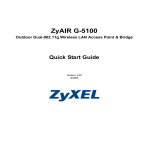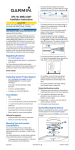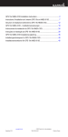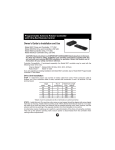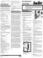
1
automatically switches off 5 seconds after it is initially plugged in
or after a power glitch.
Using the controller with a
“Universal Remote Control”
Universal handheld remote controls are popular as they can typically
control a TV, a VCR, a cable box and audio components. They are
also cheap and ideal replacements for lost and broken units. The
rotator controller will respond to commands from universal remote
controls configured to control most Pioneer® brand cable converter
boxes (HH1 mode) or most Pioneer® brand CD players (HH2 mode).
See Appendix A. Refer to the instructions supplied with the universal
remote control.
NOTES:
Channel Master cannot guarantee universal handheld remote
control compatibility.
APPENDIX A (Front Panel Setup Summary)
SET 60 Hz POWER ▲+ ▼
AT POWER UP
SET 50 Hz POWER ▲+ ▼+ SY AT POWER UP
SET REMOTE HH1
▲+ SY
AT POWER UP
SET REMOTE HH2
▼+ SY
AT POWER UP
Example: To set for 60 Hz power:
a. Disconnect the power connector at the rear of the unit.
b. Press and hold UP and DOWN in together.
c. Reconnect the power connector at the rear end of the unit.
d. Release UP and DOWN
Other functions are set in a similar manner using the following buttons
at b and d: 50Hz POWER: UP, DOWN, and SYNC Remote handheld
1 (supplied unit and most Pioneer® cable boxes): UP and SYNC
Remote handheld 2 (most Pioneer® CD players): DOWN and SYNC.
Check settings are correct by removing power for a few seconds,
then reconnect power. Display will indicate:
50H (or 50H for 50 Hz)
HH1 (or HH2 for alternate remote)
APPENDIX B (Handheld Remote Control Command Summary)
SYNC:
00▼
PROGRAM:
#▲# (# = 01-69)
DISPLAY MEMORIES/STATUS:
99 ▲
AUTOSYNC ON/RESET TO 50:
98 ▲
AUTOSYNC OFF:
98 ▼
TIMEOUT (8 MINUTES) ON:
97 ▲
TIMEOUT OFF:
97 ▼
DELETE MEMORIES/RESET:
91 ▼
APPENDIX C (Common Problems)
HANDHELD CONTROL DOES NOT FUNCTION
Battery bad or set for wrong handheld type (See Appendix A).
UNIVERSAL HANDHELD DOES NOT OPERATE CERTAIN
FUNCTIONS (eg.UP/DOWN) If supplied remote control is OK, try all
available Pioneer® cable box and Pioneer® CD player codes.
Universal remote may not be fully compatible.
UNIT DOES NOT TRACK CORRECTLY
Check power frequency 50/60 Hz setting (See Appendix A).
Check the wiring between the controller and the drive unit.
APPENDIX D (Using the rotator from any room in the house)
The following methods are products are suggested though not
endorsed by
Channel Master.
a. A UHF universal remote with a UHF to Infra-red convertor in the
same room as Model CM-9537 or:
b. An infra-red to UHF converter in each room where operation is
desired, plus a UHF to infra-red converter in the same room as
Model CM-9537.
Product Return Policy & Procedure
In Warranty / Out of Warranty / Credit Procedure Effective Immediately Warranty Period: 90-day warranty applies to all
Channel Master Products* Dealers & Consumers: Dealers and consumers can return any In-Warranty Channel Master product
to the Warranty department for repair or replacement. For In-Warranty service the consumer or dealer must call Technical
Service and request an RMA number in order to return the product. The returned product must have the RMA number visible on
the box and must include the bill of sale showing the unit is within the warranty period. If the unit is found to be defective under
our Warranty Policy Channel Master will repair or replace the item at no charge. Products outside of the warranty period should
not be returned to Channel Master with the exception of any product requested by Technical Support to be accessed for quality
assurance purposes. Technical Service Phone: +1.877.746.7261 Address: Channel Master, Consumer Warranty RMA # ----,
2260 West Broadway Road, Mesa, AZ 85202 * Some products have extended term warranty periods WARRANTY: Effective
Immediately GENERAL TERMS: 1.1 Subject to the provisions of this Warranty, CHANNEL MASTER warrants that the
equipment and software described in Paragraph 1.2 will conform to our specifications in all material respect and that the
equipment will be free from material defects in materials and workmanship during the Limited Warranty period. 1.2 This
Warranty applies to all original purchases by Customers of CHANNEL MASTER (“Equipment”).The warranties set forth herein
are not transferable. 1.3 The Effective period of this Warranty will start on the date of purchase of the Equipment or the date of
installation by a CHANNEL MASTER approved technician and will end, for the Equipment, ninety (90) days later (for all
component parts and system upgrades), unless otherwise expressed or provided herein (in each case the “Warranty Period”).
RETURN OF EQUIPMENT UNDER WARRANTY: 2.1 If an item of Equipment malfunctions or fails in normal use within the
applicable Warranty Period: (a) the Customer shall notify CHANNEL MASTER within thirty (30) days of the problem. (b)
CHANNEL MASTER will, at its option, either resolve the problem over the telephone or provide the customer with a Return
Authorization (“RMA”) Number and the address to which the customer may ship the defective item; (c) If the problem can not
be resolved over the telephone, the Customer shall attach a label showing the RMA number to each returned item, and include
a description of the problem. The Customer shall, at his or her own cost, properly pack the item to be returned, mark the RMA#
on the outside of the box, prepay the insurance and shipping charges, and ship the item to the specified CHANNEL MASTER
location. (d) Unauthorized return of any equipment, whether in or out of warranty, will be subject to a handling charge, in
addition to all repair and all transportation charges. (e) CHANNEL MASTER will, at its sole option, repair or replace the
returned item. If replaced, the replacement item may be new or refurbished; if refurbished it will be equivalent in operation to
new Equipment. If a returned item is replaced by CHANNEL MASTER, the Customer agrees that the returned item will become
the property of CHANNEL MASTER. (f) CHANNEL MASTER will complete the exchange of CHANNEL MASTER
manufactured equipment returned under this Warranty within a reasonable time, subject to lead-times from factory, and will
make a good faith effort to minimize any and all delays where possible; and (g) CHANNEL MASTER will, at its cost, ship the
repaired item or replacement to the Customer. If the Customer requests express shipping, the Customer will pay CHANNEL
MASTER an expediting fee. 2.2 Equipment which is repaired or replaced by CHANNEL MASTER under this Warranty will be
covered under all of the provisions of this Warranty for the remainder of the applicable Warranty period (for that particular
equipment) from the date of repair or replacement, whichever is longer. 2.3 If equipment is repaired beyond effective warranty
dates or if abnormal usage had occurred, Customer shall be charged applicable rates and the Customer will be advised of the
estimated charges prior to repair by CHANNEL MASTER ‘s authorized service center. 2.4 The price of out-of-warranty repairs
payable by the Customer will be based on standard labor and parts prices in effect at the time of the repair. CHANNEL MASTER
will use its best efforts to ensure that the cost of such repair, exchange, refurbishing, or substitution will not exceed the original
price of Product. 2.5 If the problem reoccurs within the warranty period, CHANNEL MASTER will, at its option: (1) re-perform
the service; (2) replace the product pursuant to the terms of this warranty, (3) permit Customer to return the product and issue
a refund pursuant to this warrant, or (4) refund the amount the Customer paid for the services. PRODUCT MODIFICATION:
4.1 CHANNEL MASTER reserves the right to make changes or improvements to its products, during subsequent production,
without incurring the obligation to install such changes or improvements on previously manufactured or sold products. FORCE
MAJEURE: 5.1 CHANNEL MASTER will not be liable if its performance under this warranty becomes commercially
impracticable due to any contingency beyond CHANNEL MASTER’s reasonable control, including acts of God, fires, flood, wars,
sabotage, civil unrest, accidents, labor disputes or shortages, government laws, rules and regulations, whether valid or invalid,
inability to obtain material, equipment or transportation, incorrect, delayed or incomplete specifications, drawings or data
supplied by Customer (collectively “Force Majeure”) LIMITATIONS AND QUALIFICATIONS OF WARRANTY: 6.1 This Limited
Warranty extends only to the original purchaser of the Equipment and is in lieu of all other express or implied warranties,
including those of merchantability and fitness for a particular purpose. This Warranty does not apply to any damage, defect of
failure caused by: (a) any part of the equipment having been modified, adapted, repaired, maintained, transported or relocated
by any person; (b) Storage or environmental characteristics which do not conform to the applicable sections of the appropriate
Equipment Manual or Instruction Sheet; (c) Failure to conform with the Equipment Operating Instructions in the applicable
Equipment Manual or Instruction Sheet; (d) External causes, including external electrical stress or lightning, or use in
conjunction with incompatible equipment, unless such use was with CHANNEL MASTER’s prior written request; (e) Cosmetic
damage; (f) Accidental damage, negligence, modification, mishandling, abuse or misuse; or (g) Force Majeure. LIMITATION
ON DAMAGES: 7.1 THIS WARRANTY IS THE CUSTOMER’S EXCLUSIVE WARRANTY FOR THE EQUIPMENT, CHANNEL
MASTER SPECIFICALLY DISCLAIMS ALL OTHER WARRANTIES OF ANY KIND, EXPRESS OR IMPLIED, INCLUDING ANY
WARRANTIES OF FITNESS FOR A PARTICULAR PURPOSE AND OF MERCHANTABILITY. 7.2 CHANNEL MASTER WILL
NOT BE LIABLE IN TORT, INCLUDING LIABILITY IN NEGLIGENCE OR STRICT LIABILITY, AND WILL HAVE NO LIABILITY
AT ALL FOR INJURY TO PERSONS OR PROPERTY. CHANNEL MASTER’S LIABILITY FOR FAILURE TO FULFILL ITS
OBLIGATIONS UNDER THIS WARRANTY OR ANY OTHER LIABILITY UNDER OR IN CONNECTION WITH THE
EQUIPMENT WILL BE LIMITED TO THE AMOUNT OF THE PURCHASE PRICE OF THE EQUIPMENT AT THE TIME OF
ORIGINAL PURCHASE. THE REMEDIES STATED IN THIS WARRANTY ARE THE CUSTOMER’S EXCLUSIVE REMEDIES
AGAINST CHANNEL MASTER REGARDING THE EQUIPMENT. 7.3 EVEN IF CHANNEL MASTER HAS BEEN NOTIFIED OF
THE POSSIBILITY OF THEM, CHANNEL MASTER WILL NOT BE LIABLE FOR ANY INDIRECT, INCIDENTAL, SPECIAL OR
CONSEQUENTIAL DAMAGES, INCLUDING LOST PROFITS AND REVENUES, FAILURE TO REALIZE EXPECTED
SAVINGS, ANY CLAIM AGAINST A CUSTOMER BY A THIRD PARTY, OR ANY OTHER COMMERCIAL OR ECONOMIC
LOSSES OF ANY KIND. 7.4 THESE LIMITATIONS AND DISCLAIMERS ARE NOT MADE BY CHANNEL MASTER WHERE
PROHIBITED BY LAW.
POSITION ACCURACY SEEMS DEGRADED
Perform SYNC function.
ANTENNA DOES NOT MOVE, BUT CONTROLLER
INDICATES MOVEMENT
www.channelmaster.com
Tel +1.877.746.7261
© 2010 Channel Master. Channel Master is a registered trademark. Specifications subject to change. All rights reserved.
Pub CM.9521A/9537.INST.20100708.
Models CM-9521A and 9537
Instruction Sheet
CAUTION: Read and Adhere to all IMPORTANT SAFEGUARDS listed elsewhere in this booklet. Read
and observe safety, installation and operating instructions supplied with this unit and with
your antenna BEFORE installation or operation. Retain this booklet and all instructions
for your safety and future reference.
IMPORTANT SAFEGUARDS
Your antenna rotator unit, consisting of a control and a drive,
has been engineered and manufactured to assure your personal
Model CM-9521A
safety, but improper installation or abuse of the unit, or the antenna
connected to it, can result in potential electrical shock or fire hazards.
In order not to defeat the safeguards incorporated in this unit, observe
the following basic rules for its installation, use and servicing.
Model
CM-9537
1. Read Instructions
All the safety and operating instructions should be read before
the product is operated.
2. Retain Instructions
The safety and operating instructions should be retained for
future reference.
3. Heed Warnings
All warnings on the product and in the operating instructions
should be adhered to.
4. Follow Instructions
All operating instructions should be followed.
5. Power Lines
An outside antenna system should not be located in the vicinity
of power lines or other electric light or power circuits, or where
it can fall into such power lines or circuits. When installing an
outside antenna system, extreme care should be taken to keep
from touching such power lines or circuits as contact with them
might be fatal.
6. Outdoor Antenna Grounding
If the drive unit is installed on an outdoor antenna, be sure the
antenna system is grounded so as to provide some protection
against voltage surges and built-up static charges. Section 810
of the National Electrical Code. ANS/NFPA70, or CSA C22.1
Sections 10, 16, and 54, of the Canadian Electrical Code,
provides information with respect to proper grounding of the mast
and supporting structure, grounding of the antenna lead-in wire to
an antenna discharge unit, size of grounding conductors, location
of antenna-discharge unit, connection to grounding electrodes,
and requirements for the grounding electrode. See separate
enclosed grounding code. See FIg A.
Example of
Antenna Grounding
According to
the National
Electrical Code
GROUND
CLAMP
ANTENNA
LEAD IN WIRE
ANTENNA
DISCHARGE UNIT
(NEC SECTION 810-20)
GROUNDING CONDUCTORS
(NEC SECTION 810-21)
ELECTRIC
SERVICE
EQUIPMENT
Fig A
NEC – National Electric Code
GROUND CLAMPS
POWER SERVICE GROUNDING
ELECTRODE SYSTEM
(NEC ART 250, PART H)
Antenna Discharge Unit is not required if lead-in conductors
are enclosed in a continuous metallic shield that is
permanently and effectively grounded.
7. Ventilation
Your control is provided with ventilation openings to allow heat
generated during operation to be released. If these openings
are blocked, heat build-up can cause failure of the control and
external damage. Therefore:
•
Never block the ventilation slots by placing it on a bed, sofa,
rug, etc.
•
Never place in a “built-in” enclosure unless proper ventilation
is provided.
•
Never cover the openings with cloth or materiel.
•
Never place near or over radiators, heat registers, amplifiers,
or other heat sources.
8. Grounding or Polarization
Your control may be equipped with a polarized AC line plug (one
blade of the plug is wider than the other). This safety feature
allows the plug to fit into the power outlet only one way. Should
you be unable to insert the plug fully into the outlet, try reversing
the plug. Should it still fail to fit, contact your electrician to replace
your obsolete outlet. Do not defeat the safety purpose of the
polarized plug.
9. Power sources
Operate the control only from an A.C. power source as indicated
on the bottom of the control. Do not use D.C.
10. Overloading
Overloaded AC outlets and extension cords are dangerous, and
so are frayed power cords and broken plugs. They may result in
a shock or fire hazard. Unplug the control and call your service
technician for replacement.
11. Power Cord Protection
Do not allow anything to rest on or roll over the power cord, and
do not place the control where power cord is subject to traffic or
abuse. Pay particular attention to the cord at the plug and the
point where it exists from the control unit. This may result in a
shock or fire hazard.
12. Object and Liquid Entry
All individuals, especially children, should be cautioned about
dropping or pushing objects into any openings. Some internal
parts carry hazardous voltages and contact can result in electrical
shock. Objects dropped into the control may also result in a fire
hazard.
13. Water and Moisture
Never expose the control to rain or water. If the control becomes
damp or wet, or if liquids are spilled into it, unplug the control
and have it inspected by a service technician before further
use. Liquids, rain or excessive moisture may cause electrical
shorts which can result in fire or shock hazards. Never operate
the control near water, such as a swimming pool, etc. or near a
bathtub, sink, laundry tub, or in a wet basement.
14. Cleaning
Unplug the control before cleaning. Use a slightly damp (not wet)
cloth. Do not use an aerosol directly on the control since it may
over spray and cause electrical shock.
16. Servicing
Any attempt to dissemble the control or drive portions of the unit
may expose you to high voltage or other hazards. Observe all
cautionary labels, warnings and safeguards.
18. Replacement Parts
When replacements parts are required, have the service
technician verify that the replacements used have the same
safety characteristics as the original parts. Unauthorized
substitutions may result in a risk of fire or electric shock, or other
risks.
19. Safety Check
Upon completion of any service or repairs to the unit, please
ask the service technician to perform routine safety checks to
determine that the unit is in a safe operating condition.
20. Lightning
For added protection of the control during a lightning storm or
when control is to be left unattended for an extended period of
time, unplug it from the wall outlet and disconnect the rotator
cable. This will prevent possible shock, fire hazard and damage
to the control due to lightning storms or power line surges.
21. Rooftop Installation
Always use extreme caution when installing a rooftop antenna
and rotator system to reduce the risk of falls. Wear rubber-soled
shoes and use a sturdy ladder. Do not install on a windy day or
when the roof is wet or is covered with ice or snow.
CONTENTS
*NOTES:
Maximum Length
Feet
Meters
180
55
200
61
280
85
310
95
445
136
510
155
2. Install drive unit. On new drive units, arrow on mast support
should be aligned with arrow shaped mast stop on housing.
Install drive unit with arrows pointing south. Using a short piece
of mast (3 feet or less), install the antenna to the drive unit
aiming the antenna south. When desired channels are close to
or on opposite sides of the north end stops, the antenna may
be installed pointing north. Note, however, that the antenna
will be pointing in the opposite direction from that indicated on
the control. An alternative means of setting up is to perform a
synchronization of the drive unit using the controller. Then set up
the antenna pointing north. Ensure power is disconnected from
the controller when making antenna adjustments.
See Fig 1 and 2.
Antenna
Loop
to allow
full turn
of antenna
Antenna Cable
Support Mast
Fig 1
1. Install 2 AAA batteries in the handheld remote.
2. Check operation by pressing the Power button and observing
the display. If it does not function, check for HH1 in power up
diagnostic display. If the display is HH2, refer to Appendix A
to change.
Attach 3 and 4 conductors to No. 3 terminals on control and drive.
Antenna Mast
Drive Unit
3 or 4 wire
rotator cable
Fig 3
CAUTION:When using jacketed cable, be sure jacket of cable passes
thru the grommet to avoid moisture collection in the cable.
4. Attach rotator cable and antenna cable securely to mast or tower,
and pass through building to TV or FM set.
NOTES: See Fig A of the Important Safeguards section regarding
grounding of the lead-in cable for lightning protection.
CAUTION:
1. Determine the AC supply voltage and frequency in your country.
The US, Canada, Japan, Taiwan and South America are
generally 120 VAC Hz. Europe, Africa, Australia and Asia (except
above mentioned) are generally 230 VAC 50 Hz. Your power
company will advise. Ensure the supplied wall plug power supply
voltage has the same input voltage as your household supply
(±10%). If not, contact your dealer.
2. Plug the power supply into the controller and the household
supply. Observe the digital diagnostic display.
It should display:
Controller Only
Handheld Unit
2 AAA Batteries
AC Adapter
Instruction Sheet
3. Disconnect the wall plug supply at the wall outlet. Connect the
cables between the controller and drive unit. See Fig B.
Connecting Cables to Controller and Drive Unit
Strip Ends 1/2"
Drive and Controller
Handheld Unit
2 AAA Batteries
AC Adapter
Instruction Sheet
CONTROLLER COMPATIBILITY
If purchased separately, the Model CM-9537 controller may be used
with the following rotator drive units:
Channel Master Models: CM-9500, 9510(A), 9512, 9513, 9515(A)
Radio Shack® Model 15-1225
Black
Model 9537
CAUTION
18VAC
1 AMP
WIDE
WIRE
Red
1" Outer
Sleeving
Green
Tower
Mounting
Fig 2
Do not mount citizens band base station antennas on top of
a standard mast mount drive unit. Mast support may become
overloaded in high winds.
UNIT MUST BE WIRED
CORRECTLY. SEE OWNER’S
GUIDE. CLASS 2 WIRING
MAY BE USED.
The exclamation point indicates the presence
of important operating and maintenance
(servicing) instructions in the literature
accompanying the appliance.
Terminal Connections
Green Wire #1 to #1
Black Wire #2 to #2
Red Wire #3 to #3
Model CM-9521A
60H (or 50H in 50 Hz countries)
HH1 (to use with the supplied handheld remote control)
If the above are not correct refer to Appendix A to change.
•
•
Model CM-9537
Before disconnecting old control box, make
note of each wire color and the corresponding
terminal connections. To reduce the risk of electric
shock, do not remove cover. No user-serviceable
parts inside. Refer servicing to qualified service
personnel.
CONTROLLER INSTALLATION
Standard
StandardMast
MastMounting
Mounting
*Mount antenna as close to rotor as possible. use no
more than 3 feet of mast in top of drive unit.
180 is South
270 is West
360 is North (fully CW viewed by a bird)
HANDHELD REMOTE SETUP
1. Determine proper size number of rotator cable from chart.
Three conductor cable is suitable, but if four conductor cable is
used, connect both conductors 3 and 4 to terminal 3 on the drive
and control.
Gage No. of Conductors AWG
MM
22
.6
3
22
.6
4*
20
.8
3
20
.8
4*
18
1.0
3
18
1.0
4*
•
•
•
Terminal Connections
ROTATOR INSTALLATION
15. Performance Change
Whenever the unit exhibits distinct change on performance,
unplug the control and call your dealer or service technician.
17. Damage Requiring Service
If the control has been dropped or the case has been damaged,
fire, and shock hazard may exist. Unplug the control and have it
checked by a service technician before use.
3. Connect rotator cable to drive unit terminal board. See Fig 3.
If you are upgrading an existing installation with Model CM-9537
controller, skip to controller installation.
Fig B
4. Reconnect the AC supply to the controller. After 5 seconds it
will switch off. Switch back on by pressing any key on the front
panel or handheld remote control. Perform a synchronization by
pressing the sync button on the left of the front panel. This takes
slightly over one minute. The unit may now be operated from the
front panel using the up and down controls.
5. Digital Compass
This feature operates as follows:
The display 000 to 360 degrees where:
•
•
000 is North (fully CCW viewed by a bird)
090 is East
3. The Up and Down controls will move the antenna position (the
same as the front panel controls). Alternately, a location may be
accessed directly using a 3 digit compass location. Example,
press 090 for East, 225 for South-West, etc.
4. Programming Preset Locations
This is the most popular mode of operation, 69 preset locations
(01 to 69) allow location numbers to be the same as TV channel
numbers if desired.
a.
b.
c.
d.
Find best signal using Up and Down controls.
Decide on a memory location, eg. 27.
Press 27 Up 27.
(Locations 01 to 09, eg. 05 may be programmed by either
05 Up 05 or 5 Up 5.)
Location is now memorized.
5. Accessing a Preset Location
As an example, to access location 27, press 27. Display will
flash “c27”, then show compass bearing while the antenna is
moving. It will become steady “c27” when it arrives.
(Locations 01 to 09, eg. 05 may be accessed as either 05 or 5).
6. Displaying Memory Locations/Status
From the handheld remote control, press 99 Up. Then observe
the display. Each programmed location is shown, followed
by its digital compass location. Additionally setting of power
frequency, handheld, autosync and timeout are shown.
A typical display might be:
60H
HH1
to on
888
Syn on
60Hz power
Handheld 1
Timeout on
End of diagnostics
Autosync on
c05 270 Compass bearing for c05
c11 090 Compass bearing for c11
c17 270 Compass bearing for c17
35
35 moves before a resync
7. Deleting Programmed Locations/Reset
Press 91 Down form the handheld remote control.
CAUTION:
Use this command with care as ALL memory locations will
be deleted. This will also set autosync off and timeout on
8. Synchronization
Press the Sync key on the left of the front panel or 00 Down
from the handheld. A counterclockwise movement is performed
to synchronize the control unit with the drive unit for proper
operation. Synchronization takes slightly over one minute.
After severe storms, or an extended period of use, the rotator
may appear to position the antenna incorrectly. First try pressing
the Sync key to re-synchronize the system. If this fails, the
antenna or drive motor may be misaligned on the mast. You may
either go to the antenna and re-orient it, or reprogram the control
unit to correspond to the new antenna orientation.
9. Auto Synchronization
The unit may be set up program a sync command automatically
after 50 pre programmed moves. This feature is switched on (or
reset to 50) by pressing 98 UP. It is switched off by pressing
98 DOWN. Check to see if active by pressing 99 UP (Display
Status) and observing “SYn on” or “SYn OFF”.
10. Timeout
The unit may be set to switch off after 8 minutes of no activity
by pressing 97 UP. This feature is deactivated by pressing 97
DOWN. Check to see if timeout is active by pressing 99 UP
(Display Status) and observing “to on” or “to OFF.” The unit