1
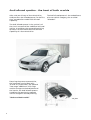
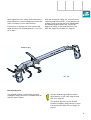
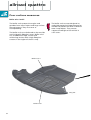
241
241
Service.
The Audi allroad quattro
with additional shift stage
Design and Function
Self-study programme 241
All rights reserved, including
the right to make technical
changes.
AUDI AG
Dept. I/VK-5
D-85045 Ingolstadt
Fax 0841/89-36367
040.2810.60.20
Technical status 11/00
Printed in Germany
For internal use only
Audi allroad quattro - the best of both worlds
After a 20 year history of four-wheel drive,
Audi presents the allroad quattro. For the first
time, a production model with off-road
capability.
The Audi allroad quattro is the embodiment
of a new vehicle category, the so-called
“allroader”.
The Audi allroad quattro is the synthesis of
the classic estate and the traditional off-road
vehicle. It combines the outstanding driving
dynamics of the Audi A6 with the off-road
capability of a four-wheel drive.
241_041
Featuring the proven quattro drive,
the improved running gear with
”4-level air suspension”, the optional
”low range” additional shift stage
and the changes to the bodywork and
the interior, the Audi allroad quattro
combines two previously separate
vehicle categories thereby offering
”the best of both worlds”.
2
241_042
Contents
Page
allroad quattro
Design features/vehicle design ............................................. 4
Engine .....................................................................................11
Gearbox ..................................................................................20
Technical data and dimensions ........................................... 22
Running gear ........................................................................ 24
Bodywork and electronics ................................................... 30
Poor surface measures ......................................................... 32
Power flow in the drive train ............................................... 34
quattro drive .......................................................................... 35
Clutch actuation ................................................................... 36
Additional shift stage
System overview ...................................................................
Operation ...............................................................................
Additional shift stage design construction ........................
Power flow .............................................................................
Electrohydraulic control ......................................................
Diagram of hydraulic system ..............................................
Hydraulic regulator ...............................................................
Shift positions/shift process ...............................................
Error functions ......................................................................
Electronic control .................................................................
Travel sensor system ............................................................
Sensors ..................................................................................
CAN information exchange .................................................
Interfaces ...............................................................................
ESP in the Audi allroad quattro............................................
Function diagram ..................................................................
38
39
40
42
44
45
46
48
54
55
56
62
65
66
67
72
Service
Self-diagnosis of the additional shift stage ....................... 74
Special tools .......................................................................... 75
The self-study programme will provide you with information on the
design and functions of the different assemblies/systems.
New
Note
Important:
Note
The self-study programme is not intended as a workshop manual.
For maintenance and repairs please refer to the current technical
literature.
Mechanical components: Workshop Manual Audi A6 1998 >
6 speed manual gearbox 01E, four wheel drive TM 3
Self-diagnosis: Workshop Manual Audi A6 1998 >
6-speed manual gearbox 01E, four wheel drive self diagnosis.
Order No.: 507.5319.01.00
This figure can be ordered as a size A0 poster through
Bertelsmann Distribution for a net price of DM 15.00 DM/7.50 EUR.
Direct ordering through Bertelsmann only applies to Germany.
Dealers in export markets are requested to contact their importer.
3
allroad quattro
The design features
The roof has the same rib structure as the
underride protection It forms an independent
design element together with the paint work,
which has been kept in the silk matt
contrasting colour.
The chunky bumpers, also highlighted in a
contrasting colour, and the prominent plastic
wheel arches emphasise the off-road qualities
of the allroad quattro and offer protection in
minor collisions.
In the special aluminium finish option the
roof rail, the trim strip on the tailgate and the
door cladding strips in aluminium are silk
matt and the side window surrounds are
highly-polished aluminium (production: all in
contrasting colour).
The integral stainless steel underride
protection, in the front and rear bumpers,
matches the aluminium finish and offers
protection against ground contact. It is also
reinforced on the inside with a plastic
honeycomb structure. In terms of
appearance, the underride protection is a
design element which emphasises the offroad capabilities of the Audi allroad quattro.
Exterior mirrors
Front space frame
241_043
Underride protection
4
Door surround strip
Extra large exterior mirrors on both sides
ensure good all-round vision, particularly off
road.
The aluminium wheels and tyres have also
been newly developed, exclusively for the
allroad quattro. Together with the other
design features, they complement the strong,
robust image of the allroad quattro.
Further information can be found under
Wheels/ tires, from page 28 on.
A unique interior design has been created for
the allroad quattro.
Attention should be drawn to the seats, which
have been newly developed for off-road use.
They combine great lateral stability with
excellent seating comfort and offer the driver
good support for sporty cornering or in
heavy, off-road terrain.
The underride protection must be
removed in order to access the rear
towing lug. It is therefore fitted with
quick-release screws.
Side window surround
Roof rail
241_044
Underride protection
Tailgate trim strip
5
allroad quattro
The vehicle design
What makes the allroad quattro an allrounder:
• quattro drive
• 4-level air suspension
• Optional activation of additional shift stage
”low range“
quattro drive
Audi has proved the
superiority of the permanent
four-wheel drive over two
decades and in all types of
terrain.
The allroad quattro is the
result of twenty-years of
quattro history.
As an all-new vehicle design,
the “allroader” demonstrates
this in a most impressive way.
Air spring/front axle
242_007
The current quattro drive
generation offers optimum
driving dynamics and safety
on all roads. However, the
quattro drive also offers a
high degree of traction and
comfort off-road and on snow
and ice.
Details of the quattro drive
can be found from page 35
on.
241_050
6
4-level air suspension
To design a vehicle which is ideal for on and off-road use,
would appear to be impossible.
Usually, the strengths of the off-road vehicle are definite
weaknesses with regard to road use.
Variable ground clearance is the solution for allroad use, in
the form of 4-level air suspension.
Air spring/rear axle
242_006
241_051
Additional shift stage
”low range“
With the help of the optional
additional “low range” shift
stage for the manual
gearbox, the overall gear
ratio is reduced by a factor
of 1.54. This increases the
traction of the allroad quattro
and also reduces the speed
by a factor of 1.54.
Additional shift stage
241_040
7
allroad quattro
4-level air suspension
A high ground clearance, essential for uneven
terrain, gives the vehicle a correspondingly
high centre of gravity.
However, this is just as disadvantageous
when cornering as it is for driving stability at
higher speeds.
Additionally, this is increases air resistance,
which significantly affects fuel consumption.
On the other hand, the reduced spring travel
and the harder set-up version of a "roadrunning gear", result in inadequate off-road
driving comfort.
The 4-level air suspension is a sophisticated
electronically controlled air suspension
system on both axles.
The system permits variation of the ground
clearance by 66 mm and offers four defined
ground clearance levels between 142 and
208 mm.
Depending on driving conditions and
requirements, greater ground clearance or a
lower vehicle centre of gravity can be
selected.
The 4-level air suspension keeps the pre-set
vehicle level constant, irrespective of load
and weight distribution.
Operating unit
241_062
8
The driver can vary the ground clearance (the
vehicle level) in four stages, by means of the
operating unit in the centre console.
The four levels can be set manually or
automatically within defined speed ranges.
It is also possible to switch between manual
and automatic mode and switch off the
system using the operating unit.
LED displays in the operating unit indicate the
operating status and the control process to
the driver.
The operation, design and function of
the 4-level air suspension is explained
in full in SSP 243.
Ground clearance
208 mm
Ground clearance
192 mm
Ground clearance
167 mm
Ground clearance
142 mm
High level 2
+ 31 mm above
normal level
High level 1
+25 mm above
normal level
Normal level
± 0 mm
Low level
-25 mm below
normal level
242_063
The ground clearance at the low level is 49 mm higher than that
of the Audi A6.
9
allroad quattro
Additional shift stage
The additional shift stage offers the following
advantages:
• Additional advantage in heavy terrain on
extreme uphill slopes via increased
traction.
• The additional shift stage makes driving
easier under difficult conditions (uphill
slopes / high loads) and protects the
clutch.
• Increased engine breaking effect on steep
downhill slopes.
• Maximum operating comfort due to
electrohydraulic control.
• Lower vehicle speeds in difficult terrain or
manoeuvring with high trailer load (up to
2300 kg).
• Electronic monitoring of shifting process
provides maximum protection against
incorrect shift procedure.
The design and function of the
additional shift stage is described in
full from page 38 on.
242_054
Vehicle speeds in 1st gear at 1000 rpm (6-speed manual gearbox)
A6
2.5-l-V6-TDI
2.7-l-V6-Biturbo
10
8.0 km/h
8.2 km/h
allroad
quattro
7.6 km/h
7.6 km/h
allroad quattro with additional
shift stage engaged
4.9 km/h
4.9 km/h
Engine
For every allroad quattro eventuality, …
... two high-performance and high-torque
engines are available.
The 2.7-l-V6-Biturbo
... is identical to the performance version
installed in the Audi S4 and A6.
Performance and torque have been adapted
for use in the allroad quattro.
Fuel grade: RON 95
In order to provide adequate fuel metering in
low-range operation, the engine control
provides a separate accelerator pedal map.
241_046
Power output diagram:
The design and function is described in
SSP 198.
The maximum power output of 184 kW is
achieved at 5800 rpm.
The maximum torque of 350 Nm is available
between 1800 and 4500 rpm.
Technical data:
Exhaust gas
standard:
Flexible service
interval:
RON 95 (RON 91 with
reduced performance)
EU III
up to 30,000 km,
max. 2 years
Power output [kW]
Fuel grade:
200
500
180
450
160
400
140
350
120
300
100
250
80
200
60
150
40
100
20
50
0
0
Torque [Nm]
Engine code: ARE
0
1000 2000 3000 4000 5000 6000 7000
Engine speed [rpm]
241_027
11
allroad quattro
The 2.5-l-V6-Biturbo
... as increased-performance version of the
2.5-1-V6-TDI with 110 kW (150PS), whose
function and design is described in SSP 183.
Power output diagram:
The increased maximum power output of
132 kW is achieved at 4000 rpm.
The maximum torque of 370 Nm is available
between 1500 and 2500 rpm.
Technical data:
Exhaust emissions
control:
Primary catalytic
converter:
Main catalytic
converter:
Emissions level:
Fuel grade:
Flexible service
interval:
Ceramic, 5.66" x 6"
and/or 2" x 5.69"/
3.3" x 6.08" (quattro)
EU III
Diesel 49 CZ
up to 35,000 km,
max. 2 years
The differences between the 132 kW
version and the 110 kW version are
described below.
12
241_047
Engine code: AKE
140
420
130
390
120
360
110
330
100
300
90
270
80
240
70
210
60
180
50
150
40
120
30
90
20
60
10
30
0
0
0
1000
2000
3000
Engine speed [rpm]
4000
5000
241_028
Comparison with V6-TDI 110 kW
Torque [Nm]
Firing order:
Turbocharger:
2496 cm3
78.3 mm x 86.4 mm
18.5 : 1
Bosch EDC-15 M with
pre-injection and dualspring injector holder
1-4-3-6-2-5
VNT 20 with variable
turbine geometry
Exhaust gas
recirculation system
Primary catalytic
converter,
Main catalytic
converter
Ceramic 3.66" x 2.9" :
Power output [kW]
Capacity:
Bore x stroke:
Compression ratio:
Fuel injection
system:
Th essential differences of the V6-TDI/132 kW
version
Piston recess
Trapezoidal head
• Pistons made of new, more heat-resistant
piston alloy to compensate for higher
thermal load.
• Altered shape of piston recess to optimise
combustion process.
ostSc
• Compression ratio reduced to
18.5 : 1 by enlarging piston recess.
• Piston/conrod with trapezoidal head to
compensate for the higher combustion
pressure and to reduce the oscillating
mass by approx. 10% (see SSP 226,
Page 10).
241_064
Increased
bearing surface
Increased
bearing surface
Vent gas
• Crankcase housing with
additional vent outlet on the
front engine side to reduce oil
component in engine ventilation.
• Reduction of the air mix in the
engine oil via lateral baffles in
the crankcase housing (see also
SSP 245 and 255).
Cyclone oil mist separator
Vent outlet
241_065
Vent outlet
13
allroad quattro
• Crankcase ventilation with cyclone oil mist
separator to reduce oil component in the
oil mist and blow-by gas (see SSP 226,
Page 17).
241_067
Principle
Due to the limited available
space the cyclone oil mist
separator consists of four
single cyclones.
These are connected in parallel
and offer the same throughput
as a single version.
Unlike oil separators with mesh
inserts (filters), the cyclone oil
mist separator cannot become
blocked.
A high functional reliability is
thus guaranteed for the service
life of the engine.
De-oiled blow-by
gas
The cyclone oil mist
separator can be also
retrofitted as a complete
unit (oil filter module) into
the 110 kW version.
241_066
Separated oil
Blow-by gas
Oil return to central crankcase
14
• Radial piston distributor fuel injection
pump VP44S3 with 3 rams for increased
injection pressure. Fuel injection
pressures of up to 1850 bar are achieved
at nominal capacity.
241_068
VP44S3 radial piston distributor fuel
injection pump
3 rams
Comparative injection pressure 110 kW with 132 kW, EU III: Maximum line pressure upstream
from the injector
2000
1800
1600
Line pressure [bar]
1400
1200
1000
800
600
400
1000
1500
2000
2500
3000
Engine speed [rpm]
110 kW, EU III
132 kW, EU III
3500
4000
4500
241_070
15
allroad quattro
• New: pre-injection controlled via solenoid valve.
In conjunction with the dual-spring injector
holder combination, it helps reduce
combustion noise, particularly when the engine
is cold.
Needle lift with pre-injection at 2500 rpm and 40 mg injection quantity
0,3
0,25
Needle lift [mm]
0,2
0,15
0,1
0,05
241_071
0
-20
-10
0
10
20
30
40
Crank angle [degrees]
• Six-hole instead of five-hole injectors for
better mixture formation and emissions
reduction.
Stop sleeve
Spring 2
Injector needle
Spring 1
Needle guide
241_069
Intermediate washer
Lift 2
0.215 mm
Lift 1
0.035 mm
16
• Primary catalytic converter
immediately downstream from the
turbocharger
Absolute charge pressure [bar]
• Turbocharger made of more heatresistant material, optimised turbine
and compressor wheel and improved
kinematics of the guide vane
adjustment.
Comparison with charge pressure curve V6-TDI
110 kW with 132 kW
2,4
2,2
2,0
1,8
1,6
1,4
1,2
1000
2000
3000
4000
Engine speed [rpm]
110 kW, EU III
132 kW, EU III
5000
241_073
Primary catalytic converter
Turbocharger with variable turbine
geometry
Main catalytic converter
241_072
Compensator
Airgap insulated front pipe
Airgap insulated manifold
17
allroad quattro
• Fuel cooling via fuel-coolant heat
exchanger and coolant-air heat exchanger
integrated into the engine cooling system
(see also SSP 226, Page 22).
• Larger oil-coolant heat exchangers
compensate the increased thermal
loading of the engine oil caused by
the increase in performance.
• To guarantee adequate engine cooling on
any terrain, the V6-TDI in the allroad
quattro is fitted with an uprated coolant
heat exchanger.
The fuel cooler is initially intended only
for the allroad quattro, but will also be
used in other vehicles in the future.
Fuel feed
Fuel return
Fuel-coolant heat exchanger
Coolant-air heat exchanger
(low temperature)
to the coolant pump
241_020
from the cooler
Coolant pump for fuel
cooling V166
18
Notes
19
allroad quattro
Gearbox
6-speed manual gearbox 01E
The following gearboxes are available for
both engine versions:
• 6-speed manual gearbox 01E
• 6-speed manual gearbox 01E with
additional low range shift stage (optional).
In conjunction with the manual gearbox 01E,
both engine versions have the self-adjusting
"SAC" clutch. The design and function is
described in SSP 198, Page 66.
The 01E manual gearbox is generally fitted
with an oil cooling system (see SSP 198,
Page 71).
241_007
20
5-speed 01V automatic gearbox
The 01V 5-speed automatic gearbox with tiptronic is also available (cannot be supplied with
additional shift stage) for the V6-Biturbo and the V6-TDI.
In both engine versions, the maximum speed is achieved in 5th gear.
241_025
Additional ATF cooler
The 01V is fitted with an
additional ATF cooling
system (see also SSP 213).
Engine cooler/
ATF cooler
241_029
Additional ATF
cooler
Return
Feed
Thermostat
21
allroad quattro
Technical data and dimensions
allroad quattro
2.7-l-V6-Biturbo
6-speed manual
gearbox
allroad quattro
2.5-l-V6-TDI
6-speed manual
gearbox
Maximum speed in km/h
236 (234)
207 (205)
Acceleration 0 - 100 km/h in s:
7.4 (7.7)
9.5 (9.6)
18.0 (19.2)
12.3 (13.4)
9.8 (9.7)
7.0 (7.5)
12.8 (13.2)
8.9 (9.6)
Urban fuel consumption in l/100 km 1):
Non-urban fuel consumption in l/100
km 1):
Overall fuel consumption in l/100 km 1):
Cooling system capacity (incl. heater) in l:
approx. 6
Engine oil capacity (incl. filter) in l:
approx. 6
Tank capacity in l:
Steering ratio:
16.2
Turning circle in m:
11.68
Unladen weight in kg (without driver):
1795 (1825)
1790 (1825)
Admissible total weight in kg:
2425 (2455)
2420 (2455)
Admissible front axle load in kg:
1260 (1285)
1270 (1285)
Admissible rear axle load in kg:
1300
Admissible unbraked trailer load in kg:
750
Admissible trailer load, braked on
8% uphill gradient, in kg 2):
2300
Admissible trailer load, braked on
12% uphill gradient in kg 2):
2100
Admissible roof load in kg:
100
Admissible support load in kg:
95
Luggage compartment capacities
according to VDA (German automobile
industry association) luggage volume
standards in l (with back seats folded down
and loaded to roof height):
1)
2)
455 - 1590
according to 93/116/EC
use of trailer anti-roll bar increases the admissible trailer load to 2300 kg
(up to max. 80 km/h)
The values in brackets relate to
automatic gearbox.
22
70
1501-1567
24
208****
142*
1056
ET25
1586**
1536
1843
1810(+33)
ET25
192***
694***
1597**
1565
1978
1950(+30)
976**
1074**
2760**
2758
4810
4797(+13)
970
1069
241_049
Dimensions: red = allroad quattro, black = A6 Avant
Values in brackets correspond to the differences in comparison with the A6 Avant.
241_026
A
A Overhang angle
Front:
B Ramp breakover
angle
C Overhang angle
rear:
D Ground clearance:
B
C
D
approx. 20 degrees
****
approx. 19 degrees
****
approx. 23 degrees
****
approx. 208 mm ****
*
**
***
****
Low level
Normal level
High level 1
High level 2
23
allroad quattro
Running gear
Features of the running gear
The running gear is from the Audi A6 quattro
and, as already mentioned, is fitted with a
self-supporting air suspension system which
can adjust the vehicle to four different levels.
The ductile cast iron pivot bearing has been
reinforced at various cross-sectional points.
The ball seats have been adapted to the
enlarged diameter of the joint pins. The
length has been adapted due to the raised
bodywork and the altered spring travel.
Due to the adaptation of the air suspension
system and the demands of all-road use, the
following modifications have been made:
Sub-frame
Front axle
The material thickness of the subframe has been increased (as for
A6 V8). The sub-frame has been
lowered in the region of the drive
shafts and the level sensor mountings
are welded. Spacers between the
bodywork and the sub-frame
mountings on the front and rear axles
serve to raise the body by 25 mm and
increase the ground clearance.
The supports at the rear mountings
have been re-dimensioned and
reinforced. A cross member serves as
reinforcement (as for the S models).
The anti-roll bar (full material, Ø29 mm
as for Audi S6) has been made
narrower due to the re-positioning of
the connecting link mountings.
Spacer
Anti-roll bar
24
The aluminium track control link has been
reinforced in cross section. The ball pivot
cross section has been enlarged and the joint
angle adapted to the kinematics. The
suspension strut eye is lower and the
mountings for the connecting link and the
level sensor have been moved inwards (to
allow free access of the connecting link to the
suspension strut).
In the case of (aluminium) guide links, the
cross section of the ball pivot has been
enlarged. The joint angle has been adapted to
the kinematics.
The joint angle of the upper, front transverse
link has also been adapted to the modified
kinematics.
The mounting bracket has been completely
re-formed and is a component part of the air
spring shock absorber.
Mounting bracket
Transverse link
Cross member
The HP2 brake system is used on
the front axle in both engine
versions (see SSP 213, Page 25).
Track control link
Guide link
241_060
25
allroad quattro
Rear axle
Spacers between the bodywork and the subframe mountings on the front and rear axles
serve to raise the body by 25 mm and
increase the ground clearance.
Tightening of the links at the front and
rear axles must be carried out at
normal vehicle level.
The upper transverse link has been modified
in shape and adapted to the air spring shock
absorber, and has been reinforced.
In the case of the (steel) wheel carriers, the
pivot point of the upper transverse link has
been raised to optimise the wheel clearance.
As a result, the modified kinematics result in
improved driving dynamics.
The track rod is made of wrought aluminium
to give greater rigidity and improved tracking
stability.
The brake cover plate has been adapted to
accommodate the wheel carrier. The
attachment points have been acoustically
optimised.
The shape of the anti-roll bar has been
adapted to accommodate the air supply unit.
Components of the allroad quattro
which could be easily confused with
standard components, are identified
with a brown dot.
The following example demonstrates
this concept:
The track rod could be confused with
that of the Audi S6.
To prevent contact corrosion, the
connection to the wheel carrier is fitted
with a steel bush.
(S6: Aluminium wheel carrier/
aluminium bush)
Anti-roll bar
241_061
Track rod
Sub-frame
Spacer
Transverse link
Wheel carrier
26
Spacers
As a result of the spacers, longer
screws are used to attach the subframe.
The spacers are eccentric.
There are two different thicknesses:
Thickness 25 mm and 23.5 mm.
The assembly instructions in the
workshop manual must be observed.
The 4 spacers on the front axle are
25 mm thick.
The spacers on the rear axle are of
different thicknesses. On the front
mountings; 23.5 mm, on the rear
mountings; 25 mm.
Spacer
241_018
Drive train
The front drive shafts have been adapted in
length to the running gear kinematics. The
inside joint is a tripod constant velocity joint,
designed as a monoblock (formed sheet
metal housing).
For info. on the tripod constant velocity joint,
see SSP 192, from Page 40 on.
The rear drive shafts have increased
diameters and the external joints have been
strengthened.
The centre support of the propshaft has been
adapted to accommodate the raised body.
The front section of the propshaft has been
shortened in combination with the additional
shift stage.
As the body has been raised with respect to
the running gear (25 mm), practically all lines
and hoses leading to the drive train and to the
running gear (e.g., brake hoses) have been
modified.
27
allroad quattro
Wheels
Aluminium wheels in two design versions are
currently available for the allroad quattro.
The standard allroad quattro has 5-spoke
wheels with dimensions 7.5 x 17 ET 25.
The winter tyre wheels and the spare wheel
(collapsible spare) are of a similar design.
Both have dimensions 6.5 x 16 ET 16.
241_052
There is an optional “Twinforce wheel”
available. Developed specially for off-road
use, it has a double spoke design.
This conceals a second supporting wheel
spider attached with titanium screws.
A high load-bearing capacity and mechanical
strength characterise this design.
The unusual design in the 7.5 x 17 ET 25
format emphasises the powerful appearance
of the allroad quattro.
241_053
To maintain clearance, snow chains
must be fitted only to the specified
winter wheels on the rear axle.
The titanium screws must on no
account not be loosened.
28
Tyres
The 225/55 R 17 97 allroad tyres have been
specially developed for the allroad quattro.
These successfully combine the conflicting
requirements of a high quality road tyre with
the demands of a good off-road tyre.
This has been achieved with new material
mixtures and a special profile.
Winter tyres: the 215/65 R 16 98 H M+S format
is admissible.
For reasons space-saving, a collapsible spare
tyre with compressor is available in
205/70-16 format.
The collapsible spare tyre can be deflated
back to its original shape. To make this easier,
the tyre valve has a protective metal cap with
which the valve insert can be removed.
This eases deflation and the tyre will return
quickly to its original shape.
241_031
Before using a jack to raise the vehicle,
switch off the air suspension.
You will find instructions for this
procedure in SSP 243, in the workshop
manual and in the operating
instructions.
Collapsible spare tyre
Compressor
241_032
29
allroad quattro
Bodywork and electronics
As well as changes to the appearance of the
bodywork, numerous reinforcement and
strengthening modifications have been made
for off-road use.
This guarantees that you never need compromise on comfort or safety when driving the
allroad quattro in off-road conditions. In
addition, the modifications all work towards
improving the long term quality body.
In addition to the bodyshell, many add-on and
in-built parts have also been reinforced. One
example is the module holder on the dash
panel.
For certain tasks related
to bodywork repair
using the bench-type
straightening system,
you will require the
portal jig supplement
VAS 5035/3 for portal jig
set VAS 5035.
241_074
30
With regard to crash safety and vehicle occupant protection, the allroad quattro fulfils the
most stringent current requirements.
Particularly in comparison with normal offroad vehicles, the allroad quattro is in a class
of its own.
With the occupant safety cell, the electronic
stability programme (ESP), a comprehensive
airbag system and the optional SIDEGUARD,
the allroad quattro offers the same high
degree of safety as the Audi A6 Avant (see
SSP 194, Page 14 and SSP 213, Page 4).
Module holder
241_075
Electrical System
The allroad quattro is fitted with dynamic
headlight range control as standard (with or
without xenon lights).
You will find design and functional
descriptions in SSP 194, Page 41 and
SSP 213, Page 65.
The special features of the allroad
quattro headlight range control system
can be found in SSP 243, on Pages 23
and 31.
31
allroad quattro
Poor surface measures
Buffer units I and II
The buffer units protect the engine and
gearbox from stone impact and large surface
ground-contact. They also serve as
soundproofing.
The buffer units are reinforced on the outside
and inside with fibreglass mats. Buffer unit 1
has an additional large surface area
reinforcing section with a high fibreglass
content in the region of the oil sump.
The buffer units are not designed as
underride protection/impact protection
and do not protect the drive if lowered
onto sharp objects. They cannot
support the weight of the vehicle in
such cases.
Buffer unit II
241_057
Buffer unit I
32
Stone impact protection for rear
transverse links and protective tube
for hand brake cable)
Stone impact protection for transverse links
Protective tube for handbrake cable
241_014
Brake line cover
241_019
Fuel line cover
Raised exhaust system with cross
member in front of the end silencers.
33
allroad quattro
Transmission ratio
1st gear
2nd gear
3rd gear
4th gear
5th gear
6th gear
Reverse gear
Axle ratio
Power flow in the drive train
6-speed 01E manual gearbox with additional shift stage
allroad quattro
2.7-l-V6-Biturbo
3.750 (3.665)
2.059 (1.999)
1.417 (1.407)
1.071 (1.000)
0.857 (0.742)
0.730 (----)
3.455 (4.096)
4.375 (3. 091)
allroad quattro
2.5-l-V6-TDI
3.750 (3.665)
2.059 (1.999)
1.320 (1.407)
0.933 (1.000)
0.730 (0.742)
0.600 (----)
3.455 (4.096)
4.375 (2.909)
The values in brackets apply to automatic transmission.
241_006
5-speed 01V automatic gearbox
Parallel-Axis-Torsen (PAT)
241_106
241_108
34
241_107
allroad quattro
Quattro drive
The allroad quattro also has a Torsen centre
differential (basic distribution 50/50) which
transmits the forces to the front and rear
axles according to the driving conditions, at
a ratio of 3 - 4 to the wheels of the axle with
better friction value.
A Torsen differential is also integrated into
the 01V 5-gear automatic gearbox, which
corresponds in terms of function to the
Torsen differential in the manual gearbox,
although its differs in design.
The design and function of the Torsen
distributor differential can be found in
SSP 76.
Parallel Axis Torsen
As the worm gears are positioned parallel to
the input / output, it is termed Parallel AxisTorsen, or PAT.
241_058
Advantages of the Torsen differential:
• Greater comfort because the locking
power of the Torsen differential is
produced purely mechanically, is always in
use and responds continuously.
• Steering control is always guaranteed.
• As long as the friction values on the
wheels are adequate, the Torsen
differential operates completely
unnoticed.
• Error conditions do not occur because the
Torsen differential operates automatically.
• The Torsen differential is largely wear-free.
Advantages of the EDL as opposed to fixed
locks:
• Full steering control is retained.
• Greater comfort as the EDL control is
activated automatically.
• Error conditions do not occur because the
system operates automatically.
The EDL function has been adapted for use in
the allroad quattro. Further information can
be found in the chapter entitled ESP influences, on Page 65.
With the Torsen differential together and the
EDL electronic differential lock function on all
wheels (effective up to 100 km/h), the allroad
quattro remains mobile even if only one
wheel has traction. The design and function
of the EDL control is described in SSP 148
and 162.
35
allroad quattro
Clutch mechanism
Clutch line with PTL valve
Due to the powerful torque of the engines in
conjunction with the torque increase caused
by the additional shift stage, the drive train
must be protected against incorrect
operation when engaging the clutch.
A PTL valve is therefore integrated into the
clutch line in the allroad quattro with
additional shift stage.
Its purpose is to prevent abrupt clutch
engagement when the clutch pedal is
released suddenly and thereby reduce the
magnitude of torque peaks.
Clutch line
Section of PTL valve
241_022
PTL valve
PTL stands for
Peak
Torque
Limiter.
i.e. limiting sudden torque peaks.
36
When the clutch is disengaged the PTL valve
opens and allows brake fluid to flow
unhindered into the slave cylinder.
PTL valve
Disengaging
241_023
to the slave cylinder
When the clutch is actuated and is engaging,
the valve is closed and the restriction bore in
the valve plate limits the return flow of fluid
into the master cylinder in the event of rapid
engagement. The engaging procedure is thus
damped, and torque peaks are prevented.
PTL valve
Engaging
241_024
Restriction bore
to the master cylinder
37
Additional shift stage
Overview of system
Motronic control
unit J220
Buzzer H3, dash panel
insert
Control unit for ESP
J104
FIS
Hydraulic pump
for additional
shift stage V190
CAN drive
Button for additional shift
stage E287
Relay for J555
additional shift
stage hydraulic
pump
Clutch pedal switch F194
Control unit
for additional
shift stage
J554
Valve for hydraulic
regulator N331
Gearbox speed sender
G182
241_030
Expansion tank
Travel sensor for hydraulic
regulator G302
38
Control unit for travel
sensor J556
Diagnostic connection
Input
CAN bus
Output
Hydraulic
Operation
The engine must be running in order to
actuate the additional shift stage.
Button on gear shift knob
The low range additional shift stage switches
electro-hydraulically by means of a button
and clutch switch. Shifting is fully
synchronised and can be actuated at any
point up to 30 km/h (when the vehicle is
standing or during driving).
The shift procedure is actuated by actuating
the clutch (fully depressed) and by
simultaneous actuation of the button on the
gear shift knob.
241_037
When the shift procedure is complete, "LOW
RANGE" appears on the FIS display of the
dash panel insert. (after approx. 0.5 second).
A flashing "LOW RANGE" display indicates an
incomplete shift procedure, e.g. due to the
clutch being engaged too soon, and prompts
the driver to repeat the procedure.
FIS display
At speeds of over 50 km/h it is impractical to
use the additional shift stage. This places
unnecessary load on the system.
If 50 km/h is exceeded while the additional
shift stage is activated, the "LOW RANGE"
message will flash and a warning tone will
sound to prompt the driver to deactivate the
additional shift stage.
If the driver fails to respond to this prompt,
the engine power will be electronically
limited above 70 km/h, to prevent damage
to the additional shift stage.
241_036
Switching on the low range additional
shift stage influences the ESP
functions.
Further details can be found under ESP
influences, from Page 65 on)
Fuel consumption increases when
using the additional shift stage.
39
Additional shift stage
Design of additional shift
stage
The speed reduction of 1.54 is effected via a
simple planetary gear set whose planet
carrier is integrated into the Torsen
differential housing.
The drive torque is transmitted to the internal
gear via the hollow shaft. The internal gear
engages with the planetary gears and is also
fixed to the coupling body 1.
The shift actuation is effected via the
hydraulic regulator under electronic control
and monitoring.
The sun gear is fixed to the synchro-hub
which carries the selector sleeve.
Shifting is effected by means of the selector
sleeve via the synchro-ring, coupling body 1
or coupling body 2 to the synchro-hub and
then to the sun gear.
Clutch-hub 2 is bolted to the housing cover
and locks the sun gear in low range
operation.
Technical data:
Internal gear
Weight, complete
with Torsen:
20.0 kg
Additional weight
compared with the
01E quattro
7.9 kg
Transmission ratio:
1.54
241_054
40
Components:
Internal gear
Planet carrier with planetary gears (Torsen)
Sun gear
Planet carrier
(bolted)
Hydraulic regulator
Synchro-ring
Coupling body 1
Selector sleeve
Synchro-ring
Coupling body 2
Synchro-hub
Output shaft
241_055
Spring
Vibration damper
Cover
41
Additional shift stage
Power flow
Low range OFF
In normal driving operation, the hydraulic
regulator is extended. The selector sleeve
connects the synchro-hub (sun gear) to the
coupling body 1 (internal gear) and thereby
couples the sun gear with the internal gear.
The planetary set is locked and the drive
torque is transmitted 1:1 to the Torsen
differential.
Low range OFF
241_081
Planetary gear set
Hydraulic regulator
241_005
Power flow
Low range OFF
Selector sleeve
42
Power flow
Low range
In low range mode the hydraulic regulator is
fully retracted. The selector sleeve connects
the synchro-hub (sun gear) to the coupling
body 2 (fixed to housing) and thus holds the
sun gear in a fixed position. The drive torque
is then transmitted via the internal gear to the
planetary gears. The planetary gears drive the
planet carrier via the locked sun gear. A transmission ratio of 1.54 is thus achieved.
Low range
241_082
Hydraulic regulator
241_004
Power flow
Low range
Selector sleeve
Sun gear
43
Additional shift stage
Electro-hydraulic control
Components in the hydraulic circuit:
• Hydraulic pump for additional shift stage
V190
During shifting, noise from the
hydraulic pump is audible.
• Hydraulic regulator consisting of:
- Solenoid valve for hydraulic regulator
N331
- Selector rod with piston and cylinder
- Travel sensor G302
• Expansion tank
Hydraulic regulator
Expansion tank
241_008
Hydraulic pump for
additional shift stage
V190
44
The hydraulic pump for additional shift
stage …
The V190 is active only during shifting (the
system works without accumulator).
... is of the gear pump design and provides
the oil pressure to the hydraulic regulator
required for gear shifting.
After a shift operation has been completed,
the system is at atmospheric pressure.
Diagram of hydraulic
system
The pressure limiting valve limits the
system pressure to approx. 40 bar.
Reservoir
Hydraulic pump
for additional
shift stage V190
Feed
M
Return
Hydraulic regulator
Oil strainer with integral
differential pressure
function
Solenoid valve for
hydraulic regulator N331
241_021
Travel sensor G302
Selector rod and pistons
Pressure limiting valve
45
Additional shift stage
Hydraulic regulator
The hydraulic regulator is an actuating
element of the shifting procedure and
features the following functions:
• Double-acting working cylinder
• Solenoid valve for hydraulic regulator
N331
• Pressure limiting valve
• Travel sensor for hydraulic regulator G302
Note:
Recognition of the precise position of the
selector fork is of great importance for
regulation in neutral position (minimal play
between low range and low range OFF).
For design reasons a precise positioning of
the mechanism of the hydraulic regulator is
required for the travel sensor’s distance
measurement system.
In order to maintain this high degree of
accuracy, the hydraulic system’s selector fork
and selector rod are bored and pinned to one
another in a defined position, by the
manufacturer.
In this way the precise position of the selector
fork with respect to the travel sensor system
is guaranteed.
For this reason, the hydraulic regulator, the
travel sensor and the selector fork are only
replaced as one complete unit.
Return
Solenoid valve for hydraulic
regulator N331
Feed
Selector rod
241_083
Travel sensor for hydraulic
regulator G302
Pressure limiting valve
Permanent magnet
Selector fork
Double-acting working cylinder
46
The solenoid valve for hydraulic regulator
N331 …
... is a so-called 3/4 way valve with
3 connections and 4 switch positions.
It is controlled by the control unit for
additional shift stage J554 with UBatt pulsewidth-modulation.
Depending on the pulse width, the valve for
the hydraulic regulator N331 moves to
positions 1 - 4 (see shift positions from
Page 48 on).
241_034
Connections:
P=
T=
A=
A
pressure connection (input)
stands for tank, meaning the return to
the expansion tank
output (control lead)
N331
T
241_094
P
Travel sensor for hydraulic regulator G302
The positions and movements of the selector
rod and thus the selector sleeve are
determined with the aid of the G302.
The control unit requires the position for the
plausibility check and monitoring of the
shifting procedure.
Further details can be found under Hydraulic
regulator travel sensor G302, Page 56.
241_035
47
Additional shift stage
Shift positions/shift
procedure
Shift position 1
From ignition “ON”, the N331 is pulse-widthmodulated for the purpose of self-diagnosis
at a pulse duty factor (PDF) of approx. 5%. This
corresponds to an average current value of
approx. 40 mA.
In position 1 the P-T-A connections of the
N331 are connected so that pressure
equalisation can take place.
Position 1 is the starting position of the N331
and enables rapid system depressurisation
after a “low range” shift procedure. Position 1
is achieved via spring force.
A break in the circuit causes a change in level
at the control unit output, which is
immediately diagnosed as an error.
To prevent incorrect operation, it must be
ensured that the hydraulic pump V190 is not
activated if a fault occurs on the N331.
Signal map
Hydraulic pump
for additional
shift stage V190
M
241_084
Filter with bypass
valve
Hydraulic regulator
A
Solenoid valve for
hydraulic regulator
N331
T
P
241_076
Pressure limiting valve
48
Shift position 2
In position 2 connections T and A are
connected.
Position 2 is for shifting to “low range” The
N331 is pulse-width-modulated at a pulse
duty factor (PDF) of approx. 20%. This
corresponds to an average current value of
approx. 600 mA.
Signal map
Hydraulic pump
for additional
shift stage V190
M
241_085
Filter with bypass
valve
Hydraulic regulator
A
Solenoid valve for
hydraulic regulator
N331
T
P
241_077
Pressure limiting valve
49
Additional shift stage
Shift position 3
In position 3 the P-T-A connections of the
N331 are connected so that pressure
equalisation can take place.
Position 3 is pulse-width-modulated at a
pulse duty factor (PDF) of approx. 35%. This
corresponds to an average current value of
approx. 1200 mA.
Position 3 is an interim setting for rapid
depressurising of the system after shifting to
“low range OFF”. Switching to position 3
ensures that the pressure in the system is
reduced during the shift from position 4 to 1.
The pressure could otherwise cause a counter
reaction at position 2.
Signal map
Hydraulic pump
for additional
shift stage V190
M
241_086
Filter with bypass
valve
Hydraulic regulator
A
Solenoid valve for
hydraulic regulator
N331
T
P
241_078
Pressure limiting valve
50
Shift position 4
In position 4 connections P and A are
connected.
Position 4 is for shifting to “low range OFF”.
The N331 is pulse-width-modulated at a pulse
duty factor (PDF) of approx. 65%. This
corresponds to an average current value of
approx. 2000 mA.
Signal map
Hydraulic pump
for additional
shift stage V190
M
241_087
Filter with bypass
valve
Hydraulic regulator
A
Solenoid valve for
hydraulic regulator
N331
T
P
241_079
Pressure limiting valve
51
Additional shift stage
Shifting procedure
Clutch pedal switch F194
Triggered by the button on the gear shift knob
E287 in conjunction with the signal from the
clutch pedal switch F195, the additional shift
stage control unit J554 checks the switch
request for plausibility and activates the relay
J555 for the hydraulic pump.
The hydraulic pump V190 then increases the
oil pressure which is fed to the hydraulic
regulator.
Button E287
Control unit J554
Shifting to low range
Relay J555
At the same time as the hydraulic pump is
activated, solenoid valve N331 moves to
position 2.
The system pressure acts essentially on the
piston rod side of the working cylinder. The
piston side is now vented to the return line
via N331. The selector rod retracts and low
range is activated (see also power flow).
“LOW RANGE” appears in the FIS display.
When the selector sleeve reaches the end
position (switch time approx. 0.5 seconds)
this is recognised by the control unit with the
aid of the travel sensor G302. The hydraulic
pump is switched off and the solenoid valve
N331 moves to position 1.
241_109
Hydraulic pump V190
Shift positions
Shift position 1
Shift position 2
Shift position 1
52
Shifting to “low range OFF”
At the same time as the hydraulic pump is
actuated, solenoid valve N331 moves to
position 4.
The system pressure acts essentially on the
piston rod side of the working cylinder. The
piston side is now also subjected to system
pressure via N331. Due to the greater piston
surface area on the piston side (greater force)
the piston rod travels outwards and low range
is deactivated (see also power flow).
“LOW RANGE” is extinguished in the FIS
display.
When the selector sleeve reaches the end
position (switch time approx. 0.5 seconds),
this is recognised by the control unit with the
aid of the travel sensor G302. The hydraulic
pump is switched off and the solenoid valve
N331 moves to position 3 for approx.
30 seconds.
This rapidly depressurises the system and
ensures that the selector rod stays in its
current position.
After approx. 30 sec., the solenoid valve N331
returns to position 1.
Shift positions
Shift position 1
Shift position 4
Shift position 3
(approx. 30 seconds)
Shift position 1
After a shift operation has been completed,
the system is at atmospheric pressure.
The low range and low range OFF settings are
retained by means of the detents on the
selector sleeve.
During shifting, noise from the
hydraulic pump is audible.
53
Additional shift stage
Malfunctions
If it is not possible to complete a shift action
before clutch engagement, the selector
sleeve will be returned to neutral position
(centre position) in order to prevent
mechanical damage.
In this case, despite a gear having been
selected, there will be no power transmission.
The “LOW RANGE” display will flash.
241_037
The shift procedure must be repeated.
The following reasons may cause a shift into
neutral:
• Excessively rapid clutch engagement.
• Incorrect setting of the clutch pedal switch
F194 or floor mat has slipped under clutch
pedal.
• Due to extremely low temperatures, the
shifting time is longer than the clutch
engaging procedure (only engage the
clutch when “LOW RANGE” appears or
extinguishes).
• Air in the system
• Insufficient pump output (e.g. voltage at
the pump for additional shift stage V190 is
too low), pump is defective or suction/
pressure lines are blocked).
FIS display
Error messages
Flashing “LOW RANGE” display signals an
undesirable condition. This could be a speed
in excess of > 50 km/h in low range or
incomplete shifting procedure.
An inverted “LOW RANGE” display indicates a
fault in the system, and prompts the owner to
contact an Audi dealership urgently.
An intermittent warning tone signals a
critical condition in the following cases:
• If the additional shift stage remains in
neutral when the engine is switched off,
an acoustic signal warns the driver that
there is no transmission power even
though a gear has been selected.
• At a speed of > 50 km/h in low range.
• Faulty synchronisation.
• Faulty hydraulic regulator.
54
Electronic control
Control unit/shifting strategies
The low range additional shift stage must
only be used with the engine running.
If the engine is switched off while in low
range, low range will automatically be
switched OFF when it is restarted and the
clutch is actuated.
This will prevent unnecessary low range
operation.
If the engine is stalled and restart within
15 seconds, low range will be retained (no
automatic OFF).
It is assumed that the driver would prefer this,
in this situation.
241_016
Fitting location:
The additional shift stage control unit J554 is
located in the housing box below the carpet
in front of the passenger seat (instead of
the control unit for the automatic gearbox).
Control unit run-on
For safety reasons, the control unit J554
remains active for approx. 30 seconds after
ignition “OFF“ (via terminal 30).
If the additional shift stage is in the neutral
position before switching off the engine
(ignition “OFF”, e.g. due to an incomplete
shift operation), there will be no power
transmission from the engine to the wheels,
despite a gear having been selected.
A vehicle parked in this way is not protected
against rolling away.
The run-on enables the control unit to
recognise this situation and switch low range
OFF after the ignition "OFF" (without
actuating the clutch).
55
Additional shift stage
Travel sensor system
Travel sensor for hydraulic regulator G302
and control unit for travel sensor J556
The travel sensor G302 is a so-called
PLCD sensor.
In order to check the plausibility of a shift
request and to monitor the shift procedure,
the control unit must know the positions and
movements of the selector sleeve at all times.
The abbreviation PLCD stands for
For this purpose the hydraulic regulator is
fitted with a travel sensor G302. Together with
the separate control unit J556, they provide
the information on the position of the piston
rod to the additional shift stage control unit
J554.
Permanent magnetic
Linear
Contactless
Displacement sensor
and describes a sensor which operates
contact-free and which detects a linear
travel distance by means of a
permanent magnet.
Travel sensor for
hydraulic regulator
G302
Control unit for
additional shift stage
J554
241_110
Hydraulic regulator
Piston rod
56
Control unit for travel sensor J556
Design of the travel sensor
The travel sensor consists of a flat steel core
which is wound along its length with a coil to
form a so-called primary coil. At each end of
the steel core are short coils, the so-called
secondary coils. Both secondary coils are
connected in series so that their phases are
inverted (opposing).
Travel sensor G302 has a permanent magnet
which is mounted on the piston of the
working cylinder. The permanent magnet
effects a local magnetic saturation of the flat
steel core and influences the induction in the
secondary coils.
The alternating current induced in them
increases sharply at first.
The position of the saturated region and
thereby the position of the piston (= position
of the selector sleeve) can thus be
determined by the coil system).
Travel sensor G302
Flat steel core
Secondary coil S2
241_095
6
5
67
7
5
12
28
9
2
4
Control unit for
additional shift
stage J554
S2
4
3
Piston
S1
P2
2
1
P1
Permanent
magnet
Control unit for
travel sensor
J556
Secondary coil S1
Hydraulic regulator
Primary coil
The travel sensor is measured and assembled together with the hydraulic sensor and
the selector fork by the manufacturer. The travel sensor forms a single unit with the
hydraulic regulator and can only be replaced as a complete unit.
Further information can be found on Page 46, “Hydraulic regulator”.
57
Additional shift stage
The primary coil is excited by a constant
square-wave alternating voltage (from control
unit J556). This induces a square-wave
alternating voltage in the secondary coils.
As previously explained, the permanent
magnet effects a magnetic saturation of the
flat steel core. The permanent magnet divides
the coil system electro-magnetically into two
areas (S1 and S2).
Excited by the primary coil, alternating
voltages are induced in the secondary coils,
which have opposite phases and different
amplitudes depending on the position of the
permanent magnet (piston position).
If the permanent magnet is located in the
centre of the two secondary coils, their
voltages increase sharply. In this position the
voltage between S1 and S2 is equal to zero.
Illustration of the travel sensor system
Relationship between the switching mechanism and the travel sensor system
3.15 V
4.09 V
5,0
2.65 V
4,0
Signal voltage
from J556 3,0
to J554 2,0
1.18 V
1,0
0
Travel in mm
Signal from the
primary coil
Signal from the
secondary coils
S1 and S2
Travel in mm 0
1
2
3
4
5
6
8
9
10
11
12
13
14
15
16
17
18
19
16.8 mm
Low range OFF
0.9 mm
Low range
8.8 mm
Mechanical mid point
(neutral position)
58
7
11.6 mm
Electrical mid point (the permanent
magnet is located centrally between
coils S1 and S2)
20
Example, measured value block 2
:
Status
1
2
3
4
Low range Off
1.00 V 4.09 V 4.09 V
16.8 mm
Neutral position
1.00 V 2.65 V 4.09 V
8.8 mm
Low range
1.00 V 1.18 V 4.09 V
0.9 mm
1st and 3rd position =the smallest or largest measured value in the basic set-up
2nd position =
current measured voltage from travel sensor system (signal voltage from
controller J556 to controller J554
4th position =
position of shift actuation in mm
Mechanical mid point
241_096
Electrical mid point
59
Additional shift stage
If the permanent magnet of one coil
is closer than the other, the effective
coil length and thereby the
inductivity increases.
• Long primary coil =
higher inductivity =
high voltage
Signal map, low range
• Short primary coil =
lower inductivity =
low voltage
Starting from the mid point of the coil
system, the phase position of the
voltage between S1 and S2 changes
depending upon the direction of
movement of the permanent magnet.
The signal from the secondary coils is
fed back to the J556 controller.
There, the phase position with
respect to the primary coil and the
amplitude (voltage) are evaluated.
The evaluation electronics of the
control unit J556 convert the results
into a linear DC voltage signal
corresponding to the piston position.
The path signal generated by the
control unit J556 is transmitted to the
additional shift stage control unit
J554.
241_089
Signal map, neutral position
241_112
60
As can be seen from fig. 241_096, the
electrical mid point does not
correspond to the mechanical mid
point.
In order that a linear output signal
can be produced, this is compensated by the evaluation electronics in
the control unit J556.
Signal map, electrical mid point
A precise fit of the selector fork to the
hydraulic regulator (see description
of hydraulic regulator) and performance of basic set-up are also
preconditions for the problem-free
function of the additional shift stage.
When carrying out basic set-up, the
control unit J554 is adapted to
recognise the mechanical end
positions of the selector fork.
Further information can be found in
the “Service” chapter under Basic setup.
241_090
Signal map, low range OFF
Measuring points on the travel
sensor
Primary coil (channel A)
Red measuring probe at pin 2
Black measuring probe at pin 1
Secondary coil (channel B)
Red measuring probe at pin 4
Black measuring probe at pin 3
A measuring adapter VAS 5258
measures the signals from the
travel sensor system.
241_088
61
Additional shift stage
Sensors
Button for additional shift stage E287 and
clutch pedal switch F194
Triggered by button E287 on the gear shift
knob in conjunction with the signal from the
clutch pedal F194, the control unit J554
checks the plausibility of the shift request
before initiating the shifting procedure.
A shifting procedure can only be carried out if
it has been ensured that the power flow to the
gearbox from the clutch has been interrupted.
The clutch pedal switch F194 performs this
monitoring function.
F194 is positioned in such a way that it is only
actuated when the clutch pedal is fully
depressed.
The precondition for correct function is the
precise positioning of F194 (see workshop
manual).
Button for additional shift stage
E287
241_036
62
Note:
Incorrect positioning of F194 can cause
problems in the function of the additional
shift stage.
Insufficient switch play:
• Shifting is not performed and/or shifts
into neutral (a floor mat which has slipped
under the clutch pedal has the same
effect).
Clutch pedal switch F194
Switch play too great (clutch does not fully
disengage).
• Excess wear in synchronisation system
and selector fork
• Shifting noise
Limit stop for F136 and F194
Clutch pedal
switch F136
Clutch pedal
Clutch pedal switch F194 must not be
confused with clutch pedal switch F36.
The switch status of clutch pedal
switch F136 is used for self-diagnosis
of F194 (see CAN information exchange
chapter).
241_056
63
Additional shift stage
Gearbox speed sender G182
The gearbox speed sender G182 works on the
induction principle and scans the 2nd gear
wheel.
In the future, gearbox speed sender
G182 will be omitted.
Originally, G182 was installed for plausibility
requests for shifting strategies.
By the end of development, a change in
shifting strategies meant that the G182 signal
was no longer required.
G182 is now used only for fault diagnosis of
“vehicle speed” information.
241_103
Gearbox speed sender G182
64
CAN information exchange
Additional low range shift stage
In the case of the additional low range shift
stage, the information exchange takes place
via the CAN drive between the additional shift
stage control unit J554 and the networked
control units, with the exception of certain
interfaces.
Control unit for additional shift
stage J554
The system overview displays the information
which is provided by the gearbox control unit
via the CAN bus and/or received and used by
the networked control units.
CAN drive high
Engine control unit:
System status (low range,
low range OFF, etc...
Engine speed
Engine torque, various
Clutch status (of F36)
Road speed
Intake air temperature
Engine control unit status
Low range display status
Switching status
Self-diagnosis fault memory entry
Speed limiter status
ESP control unit:
Wheel speed FL
Wheel speed FR
Wheel speed RL
Wheel speed RR
CAN drive low
Information sent by the J554
control unit.
Information received and
evaluated by the J554 control
unit.
For further information on the CAN
bus, please refer to SSP 186 and 213.
65
Additional shift stage
Interfaces
Terminal 30 …
... is used for the control unit run-on.
Via terminal 30, control unit J554 and thus the
whole system (including J556) remains active
for approx. 30 seconds after ignition “OFF”.
Further information on control unit run-on
can be found on Page 55.
K wire
Communication for self-diagnosis between
control unit J554 and the diagnostic tester is
effected via the familiar K wire.
A new feature is the data message, i.e. the
communication language between the
control unit and diagnostic tester.
Instead of the existing protocol KWP 1281, the
controller communicates to the additional
shift stage using the new protocol KWP 2000.
To perform self-diagnosis, the V.A.G./VAS
diagnostic tester must be equipped with the
corresponding update.
Further information can be found in the
“Service/Self-diagnosis” chapter.
66
ESP in the Audi allroad
quattro
The Bosch ESP 5.3 system forms the basis of
the driving dynamics control in the allroad
quattro (as for the Audi A6).
The most significant innovations/features are
described below.
ESP influences
To optimise “off road” characteristics, the
extended application range and the new part
system (4-level air suspension, additional
shift stage) of the allroad quattro required readaptation and extension of the part
functions of the driving dynamics control
(ESP/ABS/EDL/TCS/MSR).
The graphical display indicates which
influences of the driving dynamics control are
used when the ESP button is actuated and/or
the additional shift stage is activated.
J104
ESP normal status (after start/ignition reset)
E281
J197
E287
ESP button
ESP safety activation in
Modifications to ESP:
high level 1 for
v > 120 km/h
Modifications to ESP
high level 2 for
v > 70 km/h
Off-road ABS
Off-road EDL
Off-road ABS
ESP function passive
TCS function passive
See SSP 243, Page 13.
Additional shift stage
(optional)
241_111
67
Additional shift stage
ESP function passive
By actuating the ESP button, the ESP function
(anti-skid function) switched to passive.
This means that skidding (rotation about the
vehicle's vertical axis) will not affect the
driving dynamics control until the brake pedal
is actuated.
As soon as the “brakes actuated” information
is present, the ESP function will be
reactivated for safety reasons.
It makes sense to deactivate the ESP function
in particularly slippery terrain since
“skidding” around the vertical axis will occur
constantly.
The passive "anti-skid function" can prevent
unnecessary / undesirable ESP activation.
The ESP system cannot be switched off
with the ESP button.
Only the ESP influences can be
activated.
The ESP influences activated by the
ESP button are indicated via the ESP
warning lamps.
ESP influences are not displayed in
low range mode.
Another situation in which it is advisable to
deactivate the ESP is when “drifting” is
desired during cornering.
242_037
ESP button
68
TCS function deactivated
As is already familiar, if the ESP button
has been actuated, the TCS functions are
deactivated.
Situations in which increased wheel slip can
be advantageous:
• When driving on soft surfaces or in deep
snow.
By activating the ESP influences (via the ESP
button or in low range operation), a so-called
off-road ABS is activated.
This controls the brake pressure at the front
axle when wheel slip increases. The off-road
ABS is available up to speeds of 60 km/h.
To maintain driving stability, the rear wheels
are braked as a feature of the standard set-up.
• When rocking free a vehicle which has
become stuck.
The illustration shows ABS braking in deep
snow. Increasing wheel slip at the front axle
by approx. 15% significantly increases
deceleration and reduces the braking
distance.
Off-road ABS
The off-road ABS is automatically activated
when the additional shift stage is activated.
• When driving with snow chains.
When braking on a soft surface, the
significantly higher wheel slip and the
“wedge” of material formed in front of the
wheels reduces the braking distance.
Standard ABS
Off-road ABS
Deceleration 2.4 m/s2
Slip at the front axle approx. 10%
Deceleration 3 m/s2
Slip at the front axle approx. 25%
70
70
average slip
60
60
50
50
40
40
Speed in km/h
Speed in km/h
average slip
30
20
10
0
3
4
5
6
7
8
9
Time in seconds
Reference speed
Wheel speed, front left
Wheel speed, front right
Wheel speed, rear left
Wheel speed, rear right
10 11 12
30
20
10
0
1
2
3
4
5
6
7
8
9
10
Time in seconds
241_100
69
Additional shift stage
Electronic differential lock EDL
One of the main aims of the adaptation of
electronic differential locks via brake
intervention (EDL) is to create a locking torque
with minimum wheel slip.
The following applies:
If a high engine torque is available, the EDL
control intervenes at lower differential wheel
speeds, compared with a low engine torque.
The wheel speeds were considered as the
primary control parameters when introducing
the EDL system.
In order to protect the engine from stalling
during braking, relatively high differential
wheel speeds were necessary.
EDL control takes place in this case according
to pre-set differential wheel speeds,
depending upon the vehicle speed.
Explanation:
Since the introduction of ESP, EDL control is
performed by creating a so-called torque
balance.
The braking effect is determined by taking
account of the available engine torque and
the drive torque which can be transmitted to
the individual wheels.
The minimum control threshold is the
differential wheel speed which initiates
EDL control.
It is dependant upon the torque
balance and the vehicle speed.
Comparison of the EDL minimum control thresholds (transverse lock)
during straight-ahead driving
Speed difference of the wheels
of one axle in km/h
10
8
6
4
2
0
0
10
20
30
40
50
Speed in km/h
60
Audi A6
allroad quattro with additional shift stage
70
70
80
90
100
241_099
The EDL function has been adapted in the
following areas specifically for use in the Audi
allroad quattro and its off-road use.
• Significant reduction of the minimum
control thresholds and corresponding
adaptation to engine / gearbox versions.
• Re-adapted synchronous brake
intervention, e.g. simultaneous pressure
increase at all 4 wheels to support the TCS
function.
• Modification of the centre differential lock.
• Optimisation of diagonal brake
intervention.
• Extension of the speed limit value for EDL
control at 100 km/h.
Off-road EDL
The EDL in the allroad quattro has also been
adapted to accommodate the low range
additional shift stage.
As the wheel torque is increased by a factor of
1.54 in low range mode, it is desirable to reset
the minimum control thresholds.
As shown in illustration 241_099, the
minimum control thresholds can be very
low in low range mode.
When cornering, this would lead to
undesirable EDL control intervention.
EDL control is therefore suppressed when
cornering is detected (via the ESP input
values).
The function is automatic when
the additional shift stage has been actuated.
71
Additional shift stage
Functional diagram
Terminal 30
Terminal 15
Terminal 30
J555
V190
S
N331
M
-
+
J554
1
2
3
4
J556
E287
G182
F194
G302
31
241_009
72
Key: to the functional diagram
E287
Button for additional shift stage
F194
Clutch pedal switch
G182
G302
Gearbox speed sender
Travel sensor for hydraulic regulator
J554
J555
J556
Control unit for additional shift stage
Relay for hydraulic pump, additional
shift stage
Control unit for travel sensor
N331
Solenoid valve for hydraulic regulator
S
Fuse
V190
Hydraulic pump for additional shift
stage
1
2
3
4
Diagnostic connector for K wire
CAN drive high
CAN drive low
To buzzer H3, panel-mounted
= Input signal
= Output signal
= Positive
= Earth
= bi-directional
= CAN
73
Service
Self-diagnosis of the
additional shift stage
As already mentioned on Page 64,
communication takes place between the
control unit and the diagnostic tester using
the new data protocol KWP 2000.
The diagnostic testers must have been
updated accordingly in order to be able to
communicate with the control unit.
The VAS 5051 cannot yet be used for the new
data protocol (anticipated from Oct./2000 with
new CD 2.0 basis and corresponding
CD brand ).
Address word 22
V.A.G 1551
Program version 9.0
V.A.G 1552
Program version 6.0
Basic set-up
In order to ensure problem-free function of
the shifting system, the controller J554 is
adapted to recognise the limit positions of
the selector fork.
The basic set-up also serves as a final control
test.
For this reason you should access the fault
memory after basic set-up.
Adaption is performed using the diagnostic
testers with the aid of function 04 Basic setup (see Workshop manual).
Basic set-up must be performed:
• At every 60,000 km service
Follow the instructions given in the
Workshop manual.
• When replacing the J554 control unit (no
system function without basic set-up)
• When replacing the hydraulic regulator.
• When replacing the G302 travel sensor.
• When replacing the J556 control unit.
• When carrying out repairs to the
additional shift stage.
74
Note instructions on Page 46 and 57
when replacing the hydraulic regulator
or the travel sensor.
Special tools
Test box V.A.G 1598/18A
The V.A.G. 1598/A test box is designed as a
Y adapter and allows dynamic tests with the
control unit connected.
The V.A.G 1598/A test box replaces test
box V.A.G 1598 (T adapter).
A
8-18A
1598-18
G. 159
V.A.
V.A.G.
6
12
11
10
9
12
5
4
3
6
5
11
10
9
8
7
4
3
2
1
16
17
18
16
15
15
14
18
14
17
13
22
23
24
22
21
21
20
20
23
19
4
5
6
4
3
3
6
2
5
1
12
10
11
12
9
10
9
8
11
7
16
17
18
16
15
15
14
14
17
13
17
14
15
16
13
14
15
16
241_098
Portal jig supplement VAS 5035/3
The portal jig supplement VAS 5035/3 is used
to compensate for the raising of the body (via
spacers between the sub frame and the
body).
75
241
241
Service.
The Audi allroad quattro
with additional shift stage
Design and Function
Self-study programme 241
All rights reserved, including
the right to make technical
changes.
AUDI AG
Dept. I/VK-5
D-85045 Ingolstadt
Fax 0841/89-36367
040.2810.60.20
Technical status 11/00
Printed in Germany
For internal use only