1
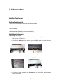
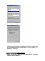
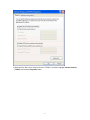
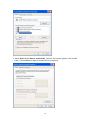
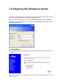
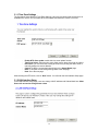
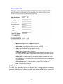
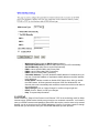
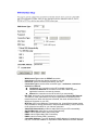
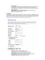
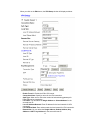
CWR-854
54Mbps Wireless-G
Router
User’s Guide
1
1 INTRODUCTION ..................................................................................................................................... 3
INSTALLING YOUR ROUTER ....................................................................................................................... 3
SYSTEM REQUIREMENTS .......................................................................................................................... 3
INSTALLATION INSTRUCTIONS ................................................................................................................... 3
2 PREPARING YOUR NETWORK .......................................................................................................... 5
PREPARING YOUR NETWORK ................................................................................................................... 5
COLLECTING ISP INFORMATION ............................................................................................................... 5
CONFIGURING WINDOWS FOR IP NETWORKING ...................................................................................... 5
3 CONFIGURING THIS WIRELESS-G ROUTER.................................................................................11
3.1 SETUP WIZARD ..................................................................................................................................11
3.1.1 Time Zone Settings.............................................................................................................. 12
3.1.2 LAN Interface Setup ............................................................................................................ 12
3.1.3 WAN Interface Setup ........................................................................................................... 13
3.1.4 Wireless Basic Settings...................................................................................................... 13
3.2 LAN SETTINGS ................................................................................................................................. 14
3.3 WAN SETTINGS ................................................................................................................................ 15
3.3.1 Static IP................................................................................................................................... 15
3.3.2 DHCP Client ........................................................................................................................... 16
3.3.3 PPPoE ..................................................................................................................................... 17
3.3.4 PPTP ........................................................................................................................................ 19
3.4 WIRELESS ......................................................................................................................................... 20
3.4.1 Basic Settings ....................................................................................................................... 20
3.4.2 Advanced Settings............................................................................................................... 22
3.4.3 Security................................................................................................................................... 23
3.4.4 Access Control ..................................................................................................................... 28
3.4.5 WDS ......................................................................................................................................... 29
3.4.6 Site Survey............................................................................................................................. 30
3.5 FIREWALL .......................................................................................................................................... 31
3.5.1 IP Filtering .............................................................................................................................. 31
3.5.2 Port Filtering.......................................................................................................................... 32
3.5.3 MAC Filtering......................................................................................................................... 32
3.6 VPN SETTINGS ................................................................................................................................. 33
3.7 ADVANCED ........................................................................................................................................ 38
3.7.1 Port Forwarding.................................................................................................................... 38
3.7.2 DMZ.......................................................................................................................................... 39
3.7.3 DDNS ....................................................................................................................................... 39
3.8 MANAGEMENT ................................................................................................................................... 40
3.8.1 Status ...................................................................................................................................... 40
3.8.2 DHCP Settings....................................................................................................................... 42
3.8.3 Time Zone Settings.............................................................................................................. 42
3.8.4 Password................................................................................................................................ 43
3.8.5 Upgrade Firmware................................................................................................................ 44
3.8.6 Remote Management .......................................................................................................... 44
3.8.7 Save/Reload Settings .......................................................................................................... 45
3.8.8 System Restart ..................................................................................................................... 45
3.9 EVENT LOG ....................................................................................................................................... 46
APPENDIX A: TROUBLESHOOTING .................................................................................................. 48
APPENDIX B: FREQUENTLY ASKED QUESTIONS.......................................................................... 51
2
1 Introduction
Installing Your Router
In this chapter, you’ll learn how to connect your router.
System Requirements
․One or more PCs (desktop or notebook) with Ethernet interface
․Broadband Internet access
․Ethernet cables
․Wireless interface (if planning to use wireless functions)
Installation Instructions
Connecting the Router:
1.
Make sure all systems are turned off, including the router, PC(s), and the cable or
DSL modem (if applicable).
2.
Connect the WAN port on the router to your cable/DSL modem, Ethernet Server, or
hub.
3.
Connect one or more client PCs to the LAN port(s).
4.
Connect the power adapter to the power jack on the router. Then, plug the power
cable into an outlet.
3
5.
Turn on your PC(s).
4
2 Preparing Your Network
Preparing Your Network
In this chapter, you’ll learn what to do before configuring your router.
Before you can configure your router, you need to set up all the computers on your network for
TCP/IP networking.
Collecting ISP Information
The following information needs to be gathered from the ISP before you can configure your
router:
․Has your ISP assigned you a static IP address, or will it be assigned dynamically? If they have
given you a static IP, what are the IP address, Subnet Mask, Default Gateway and DNS
addresses used for this connection?
․Does your ISP use PPPoE? If so, what is your PPPoE username and password?
Call your ISP if you’re not sure of the answers to these questions.
Configuring Windows for IP Networking
You need to configure each computer in your network for TCP/IP networking. If you plan to use the
DHCP feature (recommended), you should configure each computer to receive an IP address
automatically. See the procedure below.
If you don’t plan to use DHCP, you’ll need to manually assign an IP address to each computer.
Refer to your Windows documentation for instructions on IP assignment.
To configure Windows to receive dynamic IP address:
1. Click the Start button. Select Settings and click the Control Panel icon. Double-click the
Network icon.
2. On the Configuration tab, select the TCP/IP line for the applicable Ethernet adapter. Do not
choose a TCP/IP entry whose name mentions DUN, PPPoE, VPN, or AOL. If the word TCP/IP
appears by itself, select that line. Click the Properties button.
5
3. Click the IP Address tab. Select Obtain an IP address automatically
4. Now click the Gateway tab, and verify that the Installed Gateway field is Blank. Click the OK
button.
5. Click the OK button again. Windows may ask you for the original Windows installation disk or
additional files. Check for the files at c:\windows\options\cabs, or insert your Windows CD-ROM
into your CDROM drive and check the correct file location, e.g., D:\win98, D:\win9x, etc. (if “D” is
the letter of your CD-ROM drive).
6. Windows may ask you to restart your PC. Click the Yes button. If Windows does not ask you to
restart, restart your computer anyway.
1. Click the Start button. Select Settings and click the Control Panel icon. Double-click the
Network and Dial-up Connections icon.
6
2. Select the Local Area Connection icon for the applicable Ethernet adapter (usually it is the first
Local Area Connection listed). Double-click the Local Area Connection. Click the Properties
button
3. Make sure the box next to Internet Protocol (TCP/IP) is checked. Highlight Internet Protocol
(TCP/IP), and click the Properties button.
4. Select Obtain an IP address automatically. Once the new window appears, click the OK
button. Click the OK button again to complete the PC configuration.
7
5. Restart your computer.
The following instructions assume you are running Windows XP with the default interface. If you
are using the Classic interface (where the icons and menus look like previous Windows versions),
please follow the instructions for Windows 2000.
1. Click the Start button and then the Control Panel icon. Click the Network and Internet
Connections icon. Then click the Network Connections icon.
2. Select the Local Area Connection icon for the applicable Ethernet adapter (usually it is the first
Local Area Connection listed). Double-click the Local Area Connection. Click the Properties
button.
8
3. Make sure the box next to Internet Protocol (TCP/IP) is checked. Highlight Internet Protocol
(TCP/IP), and click the Properties button.
9
4. Select Obtain an IP address automatically. Once the new window appears, click the OK
button. Click the OK button again to complete the PC configuration.
10
3 Configuring this Wireless-G Router
In this chapter, it describes how to use the web management tool, a web browser-based utility that
allows you to remotely configure and manage this Wireless-G Router.
Open your Web browser and type the IP address “http://192.168.1.254” and press <ENTER>.
Enter the User name and Password when prompted, the default User name is “root”, and the
default Password is “1234”.
3.1 Setup Wizard
After successfully accessing to the configuration web page, the setup page will be shown as in the
figure below.
This Wireless-G Router has a Setup Wizard to help you easily configure its settings. Click on
“Next” to continue.
11
3.1.1 Time Zone Settings
The first step in Setup Wizard is Time Zone Settings. Users can synchronize the local clock to an
available NTP server. You can enable NTP client update and select the correct Time Zone.
-
Enable NTP client update: enable this time zone update function
Time Zone Select: Select the time zone of the country where this router is located.
NTP server: you can select the existing NTP server by clicking the down arrow or
manually assign time server address.
Cancel: To skip the current settings and jump to the Setup Wizard page.
Back: To skip the current settings and go back to the last page.
Next: Go to the next page.
After selecting the NTP server, click on “Next” button. You will enter the LAN Interface Setup page.
3.1.2 LAN Interface Setup
In the LAN interface Setup page, users can change LAN IP address and Subnet Mask here. Most
Users will not need to change these values.
12
-
IP Address: Enter IP address for this Wireless-G Router.
Subnet Mask: Enter the subnet mask for this Wireless-G Router.
Cancel: To skip the current settings and jump to the Setup Wizard page.
Back: To skip the current settings and go back to the last page.
Next: Go to the next page.
After typing in the IP Address and Subnet Mask, click on “Next” button. You will enter the Wireless
Basic Settings page.
3.1.3 WAN Interface Setup
After specifying your LAN settings, click on “Next” button. The WAN Interface Setup screen will
pop up.
-
Cancel: To skip the current settings and jump to the Setup Wizard page.
Back: To skip the current settings and go back to the last page.
Next: Go to the next page.
Users have to select the WAN Access type, WAN IP address, Subnet Mask and Default gateway.
After all items are set, click on “Next” button. You will enter the Wireless Basic Settings page.
3.1.4 Wireless Basic Settings
In the Wireless Basic Settings page, users can configure the parameters: “Band”, “Mode”,
“Network Type”, ” SSID”, and “Channel Number”.
13
-
-
-
-
Operating Band: 802.11B/G, 802.11G or 802.11B
Operating Mode: AP, Client, WDS, and AP+WDS.
Network type: when operating mode is “Client” mode, users can select the
network type as “infrastructure” or “Adhoc”.
SSID: The SSID differentiates one WLAN from another, therefore, all wireless
access points/routers and all wireless devices attempting to connect to a specific
WLAN must use the same SSID. It is case-sensitive and must not exceed 32
characters
Channel Number: The number of channels supported depends on the region of
this Wireless-G Router. All stations communicating with this Wireless-G Router
must use the same channel. (Note: not supported in client mode)
Enable Mac clone: when operating mode is “Client” mode and only one Ethernet
client exists, users can enable this Mac clone feature to connect with the wireless
station easily.
Cancel: To skip the current settings and jump to the Setup Wizard page.
Back: To skip the current settings and go back to the last page.
After all items are set, click on “Finished” button to save all the parameters you have set.
3.2 LAN Settings
“LAN Interface Setup” allows you to configure the parameters for local area network which
connects to the LAN port of your Wireless-G Router.
14
-
IP Address: Enter IP address for this Wireless-G Router.
Subnet Mask: Enter the subnet mask for this Wireless-G Router.
Default Gateway: Enter Default Gatewayfor this Wireless-G Router.
802.1d Spanning Tree: On LAN side, it supports Spanning Tree Protocol to avoid
physical loop problem.
Clone MAC Address: You can assign a new MAC address for external DHCP
server to be cloned.
Apply Changes: Click on “Apply Changes” to confirm to logout right now.
Reset: Click on “Reset” to undo your changes.
Help: To request help information.
3.3 WAN Settings
“WAN Interface Setup” allows you to configure the parameters for Internet network which connects
to the WAN port of your Wireless-G Router. There are four access types: Static IP, DHCP Client,
PPPoE and PPTP.
:
3.3.1 Static IP
If you are subscribing for a static IP from your ISP, you should select “Static IP” as your “WAN
Access Type”. You need to enter the information of IP address, Subnet Mask, Default Gateway,
Primary DNS Server and Secondary DNS Server.
15
-
-
-
WAN Access Type: select the Static IP connection
IP Address: this is the IP address that your ISP has given you.
Subnet Mask: enter the subnet mask provided by your ISP
Default Gateway: enter the default gateway provided by your ISP
DNS1: enter this Primary DNS provided by your ISP
DNS2: enter this Secondary DNS if necessary.
DNS3: enter this Tertiary DNS if necessary.
Clone MAC Address: if your ISP blocked the MAC address of a network card, you
may use “Clone MAC Address to” duplicate the MAC address to the MAC address
in the WAN port.
Enable UPnP: It allows to enable or disable uPNP feature here. After you enable
the uPNP feature, all client systems that support uPNP, like Windows XP, can
discover this router automatically and access the Internet throuth this router without
any configuration.
Apply Changes: Click on “Apply Changes” to confirm to logout right now.
Reset: Click on “Reset” to undo your changes.
Help: To request help information.
3.3.2 DHCP Client
The DHCP client also called "Dynamic IP address". DHCP is the protocol that automatically
configures an IP address, netmask, gateway, and DNS addresses. The DHCP client gets the
router's IP address and other network information. Most cable broadband service providers use
this method.
16
-
-
-
WAN Access Type: select the DHCP Client connection
Attain DNS Automatically: enable to attain DNS from your ISP automatically.
Set DNS Manually: allow user to set the DNS manually.
DNS1: enter a specific DNS to this Primary field.
DNS2: enter this Secondary DNS if necessary.
DNS3: enter this Tertiary DNS if necessary.
Clone MAC Address: if your ISP blocked the MAC address of a network card, you
may use “Clone MAC Address to” duplicate the MAC address to the MAC address
in the WAN port.
Enable UPnP: It allows to enable or disable uPNP feature here. After you enable
the uPNP feature, all client systems that support uPNP, like Windows XP, can
discover this router automatically and access the Internet throuth this router without
any configuration.
Apply Changes: Click on “Apply Changes” to confirm to logout right now.
Reset: Click on “Reset” to undo your changes.
Help: To request help information.
3.3.3 PPPoE
PPPoE stands for “Point-to-Point Protocol over Ethernet”. PPP is the technology used for dialup
Internet access. PPPoE works similarly except it works over a network connection. You'll need to
enter your PPPoE username and password. Some ISPs also require a service name to be entered.
Usually, you do not need to enter the IP/DNS addresses. However, if you have a static IP through
PPPoE, then you will need to enter your IP and DNS addresses your ISP provides.
17
-
-
-
-
WAN Access Type: select the PPPoE connection
User Name: enter the User Name provided by your ISP
Password: enter the Password provided by your ISP
Connection Type: there are three connection type – continuous, connect on
demand and manual.
Continuous: the connection to the ISP is already connected.
Connect On Demand: the connection to the ISP is build only your
application is active to connect the Internet.
Manual: the connection to the ISP is build if you set manually.
Idle Time: active only if the connection type is selected to Connect On Demand.
The idle time value is defined the time of your application not accessing to the
Internet anymore. When the idle time is reached, the router will disconnect the
WAN port connection to your ISP.
MTU Size: MTU is the Maximum Transmission Unit. It specifies the largest packet
size permitted for Internet transmission. Keep the default setting, 1452, to have the
router select the best MTU for your Internet connection.
Attain DNS Automatically: enable to attain DNS from your ISP automatically.
Set DNS Manually: allow user to set the DNS manually.
DNS1: enter a specific DNS to this Primary field.
DNS2: enter this Secondary DNS if necessary.
DNS3: enter this Tertiary DNS if necessary.
Clone MAC Address: if your ISP blocked the MAC address of a network card, you
may use “Clone MAC Address to” duplicate the MAC address to the MAC address
18
-
-
in the WAN port.
Enable UPnP: It allows to enable or disable uPNP feature here. After you enable
the uPNP feature, all client systems that support uPNP, like Windows XP, can
discover this router automatically and access the Internet throuth this router without
any configuration.
Apply Changes: Click on “Apply Changes” to confirm to logout right now.
Reset: Click on “Reset” to undo your changes.
Help: To request help information.
3.3.4 PPTP
PPTP stands for “Point-to-Point Tunneling Protocol”. PPTP is used to join 2 networks using the
Internet as an intermediary network. It allows you to connect your home and work network over the
Internet. The key is to enter the PPPTP userID, password, and PPTP Gateway IP address. The IP
addresses, subnet mask, and default gateway may or may not be required.
-
WAN Access Type: select the PPTP connection
IP Address: enter the IP Address provided by your ISP
Subnet Mask: enter the Subnet Mask provided by your ISP
Server IP Address: enter the Server IP Address provided by your ISP
User Name: enter the User Name provided by your ISP
Password: enter the Password provided by your ISP
19
-
-
-
-
MTU Size: MTU is the Maximum Transmission Unit. It specifies the largest packet
size permitted for Internet transmission. Keep the default setting, 1452, to have the
router select the best MTU for your Internet connection.
Attain DNS Automatically: enable to attain DNS from your ISP automatically.
Set DNS Manually: allow user to set the DNS manually.
DNS1: enter a specific DNS to this Primary field.
DNS2: enter this Secondary DNS if necessary.
DNS3: enter this Tertiary DNS if necessary.
Clone MAC Address: if your ISP blocked the MAC address of a network card, you
may use “Clone MAC Address to” duplicate the MAC address to the MAC address
in the WAN port.
Enable UPnP: It allows to enable or disable uPNP feature here. After you enable
the uPNP feature, all client systems that support uPNP, like Windows XP, can
discover this router automatically and access the Internet throuth this router without
any configuration.
Apply Changes: Click on “Apply Changes” to confirm to logout right now.
Reset: Click on “Reset” to undo your changes.
Help: To request help information.
3.4 Wireless
3.4.1 Basic Settings
The wireless basic settings include Band, Mode, SSID and Channel Number.
-
Disable Wireless LAN Interface: check or uncheck (Enable or Disable this
wireless interface).
Band: This Wireless-G Router can support three RF band: 802.11B/G, 802.11G
and 802.11B.
20
-
-
-
-
-
Mode: This Wireless-G Router supports four operating modes: AP, client, WDS,
and AP+WDS.
Network Type: when operating mode is Client mode, users can select the network
type as “Infrastructure” or “Adhoc” mode.
SSID: The SSID differentiates one WLAN from another, therefore, all wireless
access points/routers and all wireless devices attempting to connect to a specific
WLAN must use the same SSID. It is case-sensitive and must not exceed 32
characters.
Regulation Domain: Different countries have different Regulation Domains which
allow only specific radio frequencies.
Channel Number: The number of channels supported depends on the region of
this Wireless-G Router. All stations communicating with this Wireless-G Router
must use the same channel.
Associated Clients: When you click on the “Show Active Client” button, it will show
all the clients already associating this Wireless-G Router, see the “Active Wireless
Client Table”, only valid for AP mode and AP+WDS mode.
Enable Mac clone: when operating mode is Client mode and only one Ethernet
client exists, users can enable this Mac clone feature to connect with wireless
station easily.
Apply Changes: Click on “Apply Changes” to save the setting.
Reset: Click on “Reset” button to undo your changes.
Help: To request help information.
In the figure above, click on “Site Survey” button, the “Wireless Site Survey” table will display as
below:
-
Refresh: Click on “Refresh” button to show and renew the table.
Connect: You can select the “Select” radio button, and then click on “Connect”
button, the connection will be established.
Help: To request help information.
In the figure above, click on “Show Active Clients” button while there are wireless clients
connected to this Wireless-G Router. You will see the figure below to show the MAC address,
transmission, reception packet counters and encrypted status for each associated wireless client.
21
-
Refresh: Click on “Refresh” button to show the latest information.
Close: Click on “Close” button to close this window.
3.4.2 Advanced Settings
In Advanced Settings page, more 802.11 related parameters are tunable.
-
Authentication Type: There are three Authentication Type- Open System, Shared
Key, and Auto
Fragment Threshold: Fragmentation mechanism is used for improving the
efficiency when high traffic flows along in the wireless network. If a wireless client
often transmits large files in wireless network, you can enter new Fragment
22
-
-
-
-
-
Threshold value to split the packet. The value can be set from 256 to 2346. The
default value is 2346.
RTS Threshold: RTS Threshold is a mechanism implemented to prevent the
“Hidden Node” problem. “Hidden Node” is a situation in which two stations are
within range of the same wireless access point/router, but are not within range of
each other. Therefore, they are hidden nodes for each other. When a station starts
data transmission with the Wireless-G Router, it might not notice that the other
station is already using the wireless medium. When these two stations send data at
the same time, they might collide when arriving simultaneously at the Wireless-G
Router. The collision will most certainly result in a loss of messages of both stations.
If the “Hidden Node” problem is an issue, please specify the packet size. The RTS
mechanism will be activated if the data size exceeds the value you set. The default
value is 2347.
Beacon Interval: Beacon interval is the amount of time between beacon
transmissions. Before a station enters power save mode, the station needs the
beacon interval to know when to wake up to receive the beacon (and learn whether
there are buffered frames at the wireless router).
Data Rate: By default, it selects the highest rate for transmission.
Preamble Type: A preamble is a signal used in wireless environment to
synchronize the transmitting timing including Synchronization and Start frame
delimiter. In a “noisy” network environment, the Preamble Type should be set to
Long Preamble. The Short Preamble is intended for applications where minimum
overhead and maximum performance is desired.
Broadcast SSID: Select enabled to allow all the wireless stations to detect the
SSID of this wireless router.
IAPP: The Inter-Access Point Protocol (IAPP) can extend multi-vendor
interoperability to the roaming function.
802.11g Protection: there are CCK and OFDM modulation scheme using for
802.11b and 802.11g respectively, the packet collision will increase when these two
kind devices exist at the same time. We need to enable the Protection mode to
increase the performance.
Apply Changes: Click on “Apply Changes” to save the setting.
Reset: Click on “Reset” button to undo your changes.
Help: To request help information.
3.4.3 Security
Here you can define the security type and level of your wireless network. Selecting different
method will enable you to have different level of security. Please note that using any encryption
may be a significant degradation of the data throughput on the wireless link. There are five
Encryption types: “None”, “WEP”, “WPA(TKIP)”, ”WPA2(AES)”, and “WPA2 Mixed”.
23
-
-
-
-
Encryption: “None” means no encryption being selected. Users can enable the
802.1x Authentication and set the RADIUS server authentication parameters – port,
IP address and Password.
Use 802.1x Authentication: It is a port access protocol for protecting networks via
authentication. If a wireless user is authenticated via 802.1x for network access, a
virtual port is opened on the access point allowing for communication. If not
successfully authorized, a virtual port is not made available and communications
are blocked.
Authentication RADIUS Server: RADIUS is the Remote Access Dial-In User
Service, an Authorization, Authentication, and Accounting (AAA) client-server
protocol, which is used when a AAA dial-up client logs in or out of a Network
Access Server. Typically, a RADIUS server is used by Internet Service Providers
(ISP) to perform AAA tasks. AAA phases are described as follows:
Authentication phase: Verifies a user name and password against a local
database. After the credentials are verified, the authorization process
begins.
Authorization phase: Determines whether a request is allowed access to a
resource. An IP address is assigned for the Dial-Up client.
Accounting phase: Collects information on resource usage for the purpose
of trend analysis, auditing, session time billing, or cost allocation
You must enter this RADIUS Server’s Port number, IP address and Password
correctly.
Apply Changes: Click on “Apply Changes” to save the setting.
Reset: Click on “Reset” button to undo your changes.
Help: To request help information.
24
-
-
Encryption: Select “WEP” (Wired Equivalent Privacy) encryption type.
Set WEP Key: Only valid if not select “Use 802.1x Authentication” is not selected.
Use 802.1x Authentication: When this feature is enable, please enter the
parameters of “RADIUS Server” and select the encryption length to be “WEP
64bits” or “WEP 128bits”.
Authentication RADIUS Server: You must enter this RADIUS Server’s Port
number, IP address and Password correctly.
Apply Changes: Click on “Apply Changes” to save the setting.
Reset: Click on “Reset” button to undo your changes.
Help: To request help information.
When you click on “Set WEP Key”, the Wireless WEP Key Setup window will display
as below:
25
-
Key Length: You can choose either 64-bit or 128-bit as the encryption key.
Key Format: You can select hexadecimal or ASCII mode as the format of input
value.
Default Tx Key: You can select the default encryption Key (Key1 to Key4) being
transmitted.
Encryption Key 1: enter any key code for this Encryption Key 1.
Encryption Key 2: enter any key code for this Encryption Key 2.
Encryption Key 3: enter any key code for this Encryption Key 3.
Encryption Key 4: enter any key code for this Encryption Key 4.
Apply Changes: Click on “Apply Changes” to save the setting.
Close: To close this window.
Reset: Click on “Reset” button to undo your changes.
Help: To request help information.
26
27
-
-
-
-
Encryption: “WPA” stands for Wi-Fi Protected Access. There are three encryption
modes – TKIP, AES and Mixed.
TKIP: Temporal Key Integrity Protocol
AES: Advanced Encryption Standard
Mixed: WPA2 Mixed mode operation permits the coexistence of WPA and
WPA2 clients on a common SSID. WPA2 Mixed Mode is a Wi-Fi Certified
feature. During WPA2 Mixed Mode, the Wireless-G Router advertises the
encryption ciphers (TKIP, CCMP, other) that are available for use. The client
selects the encryption cipher it would like to use and the selected encryption
cipher is used for encryption between the client and Wireless-G Router once
it is selected by the client. The Wireless-G Router must support WPA2
Mixed Mode to use this option.
WPA Authentication Mode: There are two authentication modes, one is WPA
Enterprise By RADIUS server and the other one is WPA Personal Pre-Shared
Key.
RADIUS Server: When user chooses RADIUS authentication, there are three
parameters of RADIUS server being set – Port, IP address and Password.
Pre-Shared Key: When user chooses Pre-Shared Key authentication, there are
two types of input format – Passphrase and Hex.
Enable Pre-Authentication: Only valid for AES and Mixed mode. When user
chooses Enterprise (RADIUS), allow the radius server to do the previous
authentication process.
Apply Changes: Click on “Apply Changes” to save the setting.
Reset: Click on “Reset” button to undo your changes.
Help: To request help information.
3.4.4 Access Control
Access Control allows user to block or unblock any wireless client to access this router. Users can
add new MAC address with simple comment and then click on “Apply Changes” button to apply. To
delete a MAC address, select its corresponding checkbox under the Select column and click on
28
“Delete Selected” button.
-
-
-
Wireless Access Control Mode: There are three types of access control options:
Disable: disable this control feature.
Allow Listed: If you choose “Allow Listed”, only those clients whose
wireless MAC addresses are in the access control list will be able to connect
to your Wireless-G Router.
Deny Listed: When “Deny Listed” is selected, these wireless clients on the
list will not be able to connect to the Wireless-G Router.
MAC Address: you need to fill out the client’s MAC address which you want to
allow or deny.
Comment: you can add any comment in this blank.
Apply Changes button: when you fill up the MAC address and Comment, you
need to press this button then this information will be added to the Current Access
Control List..
Delete Selected button: delete the selected client.
Delete All button: delete all the WDS AP those are in the Current Access Control
List.
Reset button: to clear all the input in the blank.
Help: To request help information.
3.4.5 WDS
When you enable the WDS feature selected in the Basic Settings, this Wireless Distribution
System (WDS) feature will set this Wireless-G Router in “Bridge Mode”. Two Wireless-G Routers
in bridge mode can communicate with each other through wireless interface. To do this, you must
29
set these Wireless-G Routers in the same channel and set MAC address of all other Wireless-G
Routers which you want to communicate with in the table and then enable the WDS.
-
-
Enable WDS: enable the WDS function.
Add WDS AP: you need to fill out the other AP’s MAC address which you want to
communicate.
Comment: you can add any comment in this blank.
Apply Changes button: when you fill up the MAC address and Comment, you
need to press this button then this information will be added to the Current WDS
AP List..
Reset button: to clear all the input in the blank.
Set Security button: allow you to setup the wireless security for WDS.
Show Statistics button: show the MAC address, transmission and receiption
packet counters for each configured WDS AP.
Current WDS AP List: A table shows the current WDS AP’s information that
includes MAC address and comment.
Delete Selected button: delete the selected WDS AP.
Delete All button: delete all the WDS AP those are in the Current WDS AP List.
Reset: Click on “Reset” to undo your changes.
Help: To request help information.
3.4.6 Site Survey
This Wireless Site Survey tool will scan all available wireless network. Click on “Refresh” button to
search for available Wireless-G Router(s) or IBSS(s). If any Wireless-G Router or IBSS is found,
you may choose to connect it manually when client mode is enabled.
30
-
Show Client button: A table shows the assigned IP address, MAC address and
time expired for each DHCP leased client.
3.5 Firewall
3.5.1 IP Filtering
You can set up the filter against the IP addresses to block specific users from accessing the
Internet.
-
Enable IP Filtering: Enable the IP Filtering function.
Local IP Address: Enter the private IP address that you want to block accessing
the Internet.
Protocol: This allows you to select UDP, TCP or both protocol types you want to
block.
Comment: Allow user to add any description to this Local IP Address.
Apply Changes: Click on “Apply Changes” to save the setting.
Current Filter Table: A table shows the current IP Address filtering.
Delete Selected: Allow user to delete any Local IP Address in the Current Filter
Table.
31
-
Delete All: Allow user to delete all Local IP Address in the Current Filter Table.
Reset: Click on “Reset” to undo your changes.
Help: To request help information.
3.5.2 Port Filtering
The Port filtering can restrict certain type of data packets from your LAN to Internet through the
router.
-
Enable Port Filtering: Enable the Port Filtering function.
Port Range: Enter the Port range 1 to 65535 those you want to block accessing
the Internet.
Protocol: This allows you to select UDP, TCP or both protocol types you want to
block.
Comment: Allow user to add any description to this port range.
Apply Changes: Click on “Apply Changes” to save the setting.
Current Filter Table: A table shows the current port filtering.
Delete Selected: Allow user to delete any port range in the Current Filter Table.
Delete All: Allow user to delete all the port range in the Current Filter Table.
Reset: Click on “Reset” to undo your changes.
Help: To request help information.
3.5.3 MAC Filtering
You can set up the filter against the MAC addresses to block specific users from accessing the
Internet.
32
-
Enable MAC Filtering: Enable the MAC Filtering function.
MAC Address: Enter the MAC Address that you want to block accessing the
Internet.
Comment: Allow user to add any description to this MAC Address.
Apply Changes: Click on “Apply Changes” to save the setting.
Current Filter Table: A table shows the current MAC Address filtering.
Delete Selected: Allow user to delete any MAC Address in the Current Filter
Table.
Delete All: Allow user to delete all MAC Address in the Current Filter Table.
Reset: Click on “Reset” to undo your changes.
Help: To request help information.
3.6 VPN Settings
Virtual Private Network (VPN), is a connection between two end points. It establishes a private
network and allows private data to be sent securely over the Internet. This is called as “creating a
tunnel”.
33
-
-
Enable IPSec VPN: to enable IPSec VPN function.
Enable NAT Traversal: enable this function to detect NAT gateways between
IIPSec hosts and to negotiate the use of UDP encapsulation of IPSec packets.
Generate RSA Key: here you can generate a new public key.
Show RSA Public Key: to show the new public key.
Current VPN Connection Table: a table shows the current VPN connection
status.
Edit: you can edit any VPN connection in the Current VPN Connection Table.
Delete: you can delete any VPN connection in the Current VPN Connection
Table.
Refresh: to update the Current VPN Connection Table.
Show Log: to show the internal process of building VPN.
Help: To request help information.
34
When you click on the Edit button, the VPN Setup window will display as below:
-
Enable Tunnel 1: Enable the IPSec VPN tunnel.
Connection Name: Specify a name for the VPN connection.
Auth Type: Allow user to choice the method of authenticating gateways for
Diffie-Hellman key negotiation.
Local Site: You can select the Single Address or Subnet Address for the
secured local IP.
Local IP Address/Network: Enter IP address for the local network for VPN
connection.
Local Subnet Mask: Enter subnet mask the local network for VPN connection.
Remote Site: You can select the Single Address, Subnet Address, Any
Address or NAT-T Any Address for the secured remote IP.
35
-
Remote Secure Gateway: Enter remote site gateway.
Remote IP Address/Network: Enter remote site IP Address (for Single Address)
or IP network (for Subnet Address).
Remote Subnet Mask: Enter remote site subnet mask.
Local ID Type: Specify the local ID type, which is supported IP, DNS and Email.
Local ID: Specify a local ID to be used for setup VPN connection.
Remote ID Type: Specify the remote ID type, which is supported IP, DND and
Email.
Remote ID: Specify a remote ID to be used for setup VPN connection.
Key Management: there are two key management methods – IKE and Manual.
Connection Type: there are two connection types – Initator and Responder.
ESP: ESP (Encrypts Security Payload) with authentication can encrypt security
payload and authenticated for encryption service.
PreShared Key: Specify a key for IKE (Internet Key Exchange)
Remote RSA Key: Allow user to choice the method of authenticating gateways for
Diffie-Hellman key negotiation.
Status: Show the current connection status.
Advanced: Advance VPN setup for IKE.
Connect: To active the VPN connection.
Disconnect: To inactive the VPN connection.
Apply Changes: Click on “Apply Changes” to save the setting.
Reset: Click on “Reset” to undo your changes.
Refresh: to update the Current VPN Connection Status.
Back: go back to the VPN Setup page.
Help: To request help information.
When you select to set the key management manually, you have to click on the
Advanced button, the Advanced VPN Settings for IKE web page will display
36
Phase 1
- Negotiation Mode: This negotiation is a main process to build a VPN connection in
phase 1.
- Encryption Algorithm: There are two encryption algorithm – 3DES and AES128.
- Authentication Algorithm: There are two authentication algorithm – MD5 and
SHA1.
- Key Group: There are three Key groups to be defined – DH1, DH2 and DH5.
- Key Life Time: Define the life time for this key.
Phase 2
- Active Protocol: The ESP protocol is using to build a VPN connection in phase 2
- Encryption Algorithm: There are three encryption algorithm – 3DES, AES128 and
Null.
- Authentication Algorithm: There are two authentication algorithm – MD5 and
SHA1.
- Key Life Time: Define the life time for this key.
- Encapsulation: Show the current encapsulation mode.
- Perfect Forward Secrecy (PFS): A key-establishment protocol, used to secure
VPN communications. If one encryption key is compromised only data encrypted
by that specific key is compromised. For perfect forward secrecy (PFS) to exist the
key used to protect transmission of data must not be used to derive any additional
keys. You can turn on this PFS feature.
- OK: Click on “OK” to confirm the setting.
- Cancel: Click on “Cancel” to skip the setting on this page.
37
-
Help: To request help information.
3.7 Advanced
3.7.1 Port Forwarding
The Port Forwarding allows you to re-direct a particular range of service port numbers (from the
WAN port) to a particular LAN IP address. It helps you to host some servers behind the router’s
NAT firewall.
-
-
Enable Port Forwarding:
IP Address: This is the private IP of the server behind the NAT firewall.
(Note: You need to give your LAN PC clients a fixed/static IP
address for Port Forwarding to work properly.)
Protocol: This is the protocol type to be forwarded. You can choose to forward
“TCP” packet, “UDP” packet or “Both” (TCP + UDP).
Port Range: The range of ports to be forward to the private IP.
Comment: Allow user to add any description to this Port Forwarding.
Apply Changes: Click on “Apply Changes” to save the setting.
Current Port Forwarding Table: A table shows the current Port Forwarding
settings.
Delete Selected: Allow user to delete any Port Forwarding settings in the Current
Port Forwarding Table.
Delete All: Allow user to delete all Port Forwarding settings in the Current Port
Forwarding Table.
Reset: Click on “Reset” to undo your changes.
Help: To request help information.
38
3.7.2 DMZ
DMZ feature allows one local user to be exposed to the Internet for use of a special-purpose
service such as Internet gaming or videoconferencing. It will forward all the ports at the same time
to one PC. The port forwarding feature is more secure because it only opens the ports you want to
have opened, while DMZ opens all the ports of one computer, exposing the computer so the
Internet can see it.
-
-
Enable DMZ: Enable one PC to be exposed to the Internet.
DMZ Host IP Address: Enter the computer’s IP address in this field.
(Note: You need to give your LAN PC clients a
fixed/static IP address for DMZ to work properly.)
Apply Changes: Click on “Apply Changes” to save the setting.
Reset: Click on “Reset” to undo your changes.
Help: To request help information.
3.7.3 DDNS
You can assign a fixed host and domain name to a dynamic Internet IP address. Each time the
router boots up, it will re-register its domain-name-to-IP-address mapping with the DDNS service
provide. This is the reason that Internet users can access the router through a domain name
instead of its IP address.
(Note: make sure that you have registered with a DDNS service provider before enabling
this feature.)
39
-
Enable DDNS: Enable this DDNS function.
Service Provider: Select the DDNS Service Provider.
Domain Name: Enter the Service Provider Domain Name if needed.
Username/Email: Enter the user name or Email address required to log into the
DDNS account
Password/Key: Enter the password or Key number required to log into the DDNS
account.
Apply Changes: Click on “Apply Changes” to save the setting.
Reset: Click on “Reset” to undo your changes.
Help: To request help information.
3.8 Management
3.8.1 Status
This status page provides a brief read-only report for system, LAN and WAN configuration
information. The data displayed may be changed depending on your current configuration.
40
System
- Uptime: The date/time shows how long the router power on.
- Firmware Version: Show the current firmware version.
Wireless Configuration
- Mode: Shows the current operating modes.
- Band: Shows the current operating band.
- SSID: Shows the current SSID.
- Channel Number: Shows the current operating channel.
- Encryption: Shows the current encryption mode.
- BBSID: Shows the current BBSID on your Wireless LAN port.
- Associated Clients: Shows the number of associated clients that you are
connecting together.
TCP/IP Configuration
- Attain IP Protocol: Shows the IP protocol is being used on LAN
- IP Address: Shows the router’s LAN port IP address
- Subnet Mask: Shows subnet mask on your local network.
- Default Gateway: Shows the defined Default Gateway on your local network.
41
- DHCP Server: Shows the DHCP server status.
- MAC Address: Shows the MAC address on your LAN port.
WAN Configuration
- Attain IP Protocol: Shows the IP protocol is being used on WAN.
- IP Address: Shows the router’s WAN port IP address
- Subnet Mask: Shows subnet mask on your public network.
- Default Gateway: Shows the defined Default Gateway on your public network.
- MAC Address: Shows the MAC address on your WAN port.
3.8.2 DHCP Settings
There is a DHCP server running on LAN interface. It serves dynamic IP addresses to LAN hosts
running DHCP client. Both dynamic and static DHCP leases are supported. The service is turned
on by default.
-
Enable DHCP Server: Check the checkbox to enable the DHCP Server feature.
DHCP Client Range: Enter the Start / End address that should be assigned by the
DHCP server.
Apply Changes: Click on “Apply Changes” to save the setting.
Reset: Click on “Reset” to undo your changes.
Refresh: Click on “Refresh” button to update the latest information in the Dynamic
DHCP Client List.
Help: To request help information.
3.8.3 Time Zone Settings
This wireless router provides a NTP (Network Time Protocol) client that can synchronize time with
configured NTP server. Press the Refresh Time button refreshes system timestamp and the
Save/Time Sync buttons force NTP client sync time with NTP server.
42
-
Current Time: Show the current time of this router.
Time Zone Select: Select the time zone of the country where this router is located.
Enable NTP client update: enable this time zone update function
NTP server: you can select the existing NTP server by clicking the down arrow or
manually assign time server address.
Apply Changes: Click on “Apply Changes” to save the setting.
Reset: Click on “Reset” to undo your changes.
Refresh: Get the date/time from NTP server again.
Help: To request help information.
3.8.4 Password
Users can change User Name and Password here. The default User Name is “root” with
Password “1234”.
-
User Name: Enter the new login user name. The user name can contain 1 to 30
characters and/or digits, and are case sensitive. (Note: if you empty the user
43
-
name, the password login protection will be disable.)
New Password: Enter the new login password. The passwords can contain 1 to 30
characters and/or digits, and are case sensitive.
Confirmed Password: Enter the new login password again.
Apply Changes: Click on “Apply Changes” to save the setting.
Reset: Click on “Reset” to clear all fields.
Help: To request help information.
3.8.5 Upgrade Firmware
This wireless router allows you to easily upgrade the firmware.
Firmware Upgrade: Click on the Browse button to select the firmware and then click on the
Upload button. After the firmware upgrade is completed, the router will restart automatically.
(Note: Do not power off the device while the firmware is being upgraded.)
-
Select File: Enter the location and name of the file containing the new firmware.
You can use the Browse button next to this filed to browse for the file.
Upload: Click to upgrade the router’s firmware.
Reset: Click on “Reset” to clear the Select File fields.
Help: To request help information.
3.8.6 Remote Management
Users can connect to this router from remote side using this router’s WAN IP. This router’s current
WAN IP is shown in the WAN status page.
.
-
Enable Web Server Access on WAN: Check the checkbox and enable this
remote feature.
Apply Changes: Click on “Apply Changes” to save the setting.
44
-
Reset: Click on “Reset” to undo your changes.
Help: To request help information.
3.8.7 Save/Reload Settings
You can create a backup file that contains your current router settings. After you create a backup
file, you can use it to restore your settings in the event you need to reset the router’s defaults.
-
Save Settings to File: Click on “Save” button to save the settings to a file
“config.dat”.
-
Load Settings from File: Enter the location and name “config.dat” of the file which
was saved. You can use the “Browse” button next to this field to browse for the file.
Upload: Click on “update” button to upload the previous settings.
Reset Settings to Default:: You can click on the “Reset” button to reset the current
configuration to the factory default
Help: To request help information.
-
3.8.8 System Restart
You can restart the system on this page to replace the “power off “and “power on” action on this
router.
45
-
Apply Changes: Click on “Apply Changes” to confirm to reset this router.
Help: To request help information.
3.9 Event Log
This wireless router supports System Log information. This data is useful for monitoring and
troubleshooting the network.
-
Enable Log: Enable the Log function.
Wireless only or system all: Select to log the wireless events only or all system
events.
Enable Remote Log: Enable the Remote Log function.
Log Server IP Address: You have to enter the Remote Log Server IP address
when you use the Remote Log function. Logs can be sent to a remote server
46
-
running a syslog daemon.
Apply Changes: Click on “Apply Changes” to save the setting.
Refresh: Get the log data again.
Clear: Click on “Clear” to clear all log data in the message box.
Help: To request help information.
47
Appendix A: Troubleshooting
Symptom
Inability to connect physically
Possible Causes
Things to Do
• Verify that the wireless
• Incorrect or incompatible
wireless network configuration. network configurations
between the wireless client
For example, shared key
authentication is configured on and wireless AP/Router are
the wireless AP/Router and the compatible.
wireless client is attempting
•Using utility “Ipconfig”:
open system authentication
1. Click Start > Programs and
• Inadvertent media access
control (MAC) address filtering select Command Prompt.
2. Type ipconfig /all at the
• The wireless network name command prompt.
3. Write down any
is not visible
configuration information you
will need. At a minimum it will
be the IP address of your
computer and the Default
Gateway.
Make sure the client’s IP
network is same as your
AP/Router.
• The wireless AP/Router and
wireless network adapter are
not using the same 802.11
standard (for example, you are
using an 802.11a network
adapter and a 802.11g
wireless AP/Router)
• Use the same 802.11
standard for wireless
AP/Router and wireless
network adapter.
• Radio frequency (RF)
interference from nearby
devices such as cordless
phone and Bluetooth devices
• Remove the devices which
cause the interference.
• Wireless client is at the
periphery of the RF range of
the wireless AP/Router
• Move the wireless client
which is at the periphery of the
RF range more closer to the
wireless AP/Router..
• Improperly functioning or
outdated wireless network
adapter driver
• Obtain and install the most
recent version of the wireless
network adapter driver.
48
Intermittent connectivity
• Cable failure
• Check the “Link” LED. Make
sure that your Ethernet cables
connect properly.
• AP/Router is not power on
• Check the “Power” LED.
Make sure that you've plugged
in the power cord.
• IEEE 802.1X authentication
is enabled on the wireless
client and is not enabled on
the wireless AP/Router
• The symptom of this issue is
when the wireless client loses
connectivity every 3 minutes or
so. Disable the authentication
feature on the wireless client.
• Improperly functioning or
outdated wireless network
adapter driver
• Obtain and install the most
recent version of the wireless
network adapter driver.
• Improperly functioning
wireless AP/Router
Incorrect, missing, or stale
visible networks
• Improperly functioning or
outdated wireless network
adapter driver
• Obtain and install the most
recent version of the wireless
network adapter driver.
• Improperly functioning radio • Run diagnostic functions on
equipment on wireless
the wireless network adapter.
AP/Router or wireless network
adapter
Wireless client has associated • Authentication problem
but no there is no valid IP
address configuration or no
• Incorrect encryption key
network connectivity
• Bad or missing certificates
• Improperly functioning
wireless AP
• Verify that the wireless
network configurations
between the wireless client
and wireless AP/Router are
compatible.
• If you are using a static WEP
key, verify that it has been
correctly configured.
• Verify whether other
computers connected to the
wireless AP have the same
problem. If all wireless clients
of the same wireless
AP/Router have the same
problem, check the wireless
AP/Router settings.
• IEEE 802.1X authentication
might be failing. Check it
again.
Wireless connection problems
when performing a suspend
and resume with a laptop
computer
• The Wireless Zero
Configuration or Wireless
Configuration services are not
running
• Improperly functioning or
49
• Check to see if the Wireless
Zero Configuration or Wireless
Configuration services are
running with the sc query
wzcsvc command.
outdated wireless network
adapter driver
• With the Services snap-in,
ensure that the Wireless Zero
Configuration or Wireless
• On a laptop computer, the
Configuration services are
wireless radio button might be configured to start
in the off position
automatically.
• A wireless network adapter
driver failing in early stages of
service startup may result in
the Wireless Zero
Configuration or Wireless
Configuration service not
initializing over that interface.
Client can't connect to the
AP/Router's configuration
utility.
• Wrong IP address
50
• Make sure that your PC is
using an IP address within the
correct range. It should be
192.168.1.2 to 192.168.1.254
for the default value.
• Make sure that the address
of the subnet mask is
255.255.255.0.
• Try to use “Ping” utility to ping
the AP/Router’s IP, the default
IP should be at 192.168.1.253
or 192.168.1.254 for AP and
Router respectively.
Appendix B: Frequently Asked Questions
Q1: What is wireless networking?
Ans: The term wireless networking refers to technology that enables two or more computers to
communicate using standard network protocols, but without network cabling. Strictly speaking, any
technology that does this could be called wireless networking. The current buzzword however
generally refers to wireless LANs. This technology, fuelled by the emergence of cross-vendor
industry standards such as IEEE 802.11, has produced a number of affordable wireless solutions
that are growing in popularity with business and schools as well as sophisticated applications
where network wiring is impossible, such as in warehousing or point-of-sale handheld equipment.
Q2: What is a wireless network made up of?
Ans: There are two kinds of wireless networks:
a. An ad-hoc, or peer-to-peer wireless network consists of a number of computers each equipped
with a wireless networking interface card. Each computer can communicate directly with all of the
other wireless enabled computers. They can share files and printers this way, but may not be able
to access wired LAN resources, unless one of the computers acts as a bridge to the wired LAN
using special software. (This is called "bridging")
Figure A1: Ad-Hoc or Peer-to Peer Networking.
Each computer with a wireless interface can communicate directly with all of the others.
b. A wireless network can also use an access point, or base station. In this type of network the
access point acts like a hub, providing connectivity for the wireless computers. It can connect (or
"bridge") the wireless LAN to a wired LAN, allowing wireless computer access to LAN resources,
such as file servers or existing Internet Connectivity.
There are two types of access points:
i. Dedicated hardware access points (HAP) such as Lucent's WaveLAN, Apple's Airport Base
Station or WebGear's AviatorPRO. (See Figure A2). Hardware access points offer comprehensive
support of most wireless features, but check your requirements carefully.
ii. Software Access Points which run on a computer equipped with a wireless network interface
card as used in an ad-hoc or peer-to-peer wireless network. (See Figure A3) The Vicomsoft
InterGate suites are software routers that can be used as a basic Software Access Point, and
include features not commonly found in hardware solutions, such as Direct PPPoE support and
extensive configuration flexibility, but may not offer the full range of wireless features defined in the
802.11 standard.
With appropriate networking software support, users on the wireless LAN can share files and
printers located on the wired LAN and vice versa. Vicomsoft's solutions support file sharing using
TCP/IP.
51
Figure A2: Hardware Access Point.
Wireless connected computers using a Hardware Access Point.
Figure A3: Software Access Point.
Wireless connected computers using a Software Access Point.
Q3: Can I mix wireless equipment from different vendors?
Ans: Because most wireless networking hardware vendors support the 802.11 standard they can
inter operate. However, we recommend verification as the standard is a fairly recent one, and does
specify two different methods for wireless communications; Frequency Hopping (FH) and Direct
Sequence Spread Spectrum (DSSS or DS), which are not interoperable.
When purchasing wireless networking hardware from separate vendors be sure to obtain
guarantees from the vendors that the hardware will interoperate and follows the standards.
Within a short time we expect all new wireless cards, like Ethernet cards, to become inexpensive,
ubiquitous and totally interoperable.
Also of note is that the latest version of the standard defines 11mbps and 5.5mbps networking,
with support for the older standard 1mbps and 2mbps speeds. This provides some compatibility
with different or older equipment. Note that this new standard covers DS-type Networks, not FH
types.
Software access points such as InterGate which uses the wireless interface of the host computer
should have no compatibility issues with third party wireless hardware, as long as standards are
followed. Typically wireless hardware is identified to the software as a network interface, and
therefore can be used in the same way as any other network card.
Q4:If my computer is connected to a wireless LAN, can it communicate with computers on a wired
LAN as well?
Ans: To do this you will need some sort of bridge between the wireless and wired network. This
can be accomplished either with a hardware access point or a software access point. Hardware
access points are available with various types of network interfaces, such as Ethernet or Token
Ring, but typically require extra hardware to be purchased if your networking requirements
change.
If networking requirements go beyond just interconnecting a wired network network to a small
wireless network, a software access point may be the best solution.
A software access point does not limit the type or number of network interfaces you use. It may
52
also allow considerable flexibility in providing access to different network types, such as different
types of Ethernet, Wireless and Token Ring networks. Such connections are only limited by the
number of slots or interfaces in the computer used for this task.
Further to this the software access point may include significant additional features such as shared
Internet access, web caching or content filtering, providing significant benefits to users and
administrators.
Q5: What is Roaming?
Ans: A wireless computer can "roam" from one access point to another, with the software and
hardware maintaining a steady network connection by monitoring the signal strength from in-range
access points and locking on to the one with the best quality. Usually this is completely transparent
to the user; they are not aware that a different access point is being used from area to area. Some
access point configurations require security authentication when swapping access points, usually
in the form of a password dialog box.
Access points are required to have overlapping wireless areas to achieve this as can be seen in
the following diagram:
Figure A6: Roaming.
A user can move from Area 1 to Area 2 transparently. The Wireless networking hardware
automatically swaps to the Access Point with the best signal.
Not all access points are capable of being configured to support roaming. Also of note is that any
access points for a single vendor should be used when implementing roaming, as there is no
official standard for this feature.
Q6: What about security?
Ans: Wireless communications obviously provide potential security issues, as an intruder does not
need physical access to the traditional wired network in order to gain access to data
communications. However, 802.11 wireless communications cannot be received --much less
decoded-- by simple scanners, short wave receivers etc. This has led to the common
misconception that wireless communications cannot be eavesdropped at all. However,
eavesdropping is possible using specialist equipment.
To protect against any potential security issues, 802.11 wireless communications have a function
called WEP (Wired Equivalent Privacy), a form of encryption which provides privacy comparable to
that of a traditional wired network. If the wireless network has information that should be secure
then WEP should be used, ensuring the data is protected at traditional wired network levels.
Also it should be noted that traditional Virtual Private Networking (VPN) techniques will work over
wireless networks in the same way as traditional wired networks.
Section Two - Wireless Networking and the Internet
Q7: How can I use a wireless network to share an Internet connection?
Ans: Once you realize that wireless cards are analogous to Ethernet cards and that empty space
53
is analogous to Ethernet cabling, the answer to this question becomes clear. To share an Internet
connection across a LAN you need two things:
(1) an Internet sharing hardware device or software program
(2) connection to a LAN
If your LAN is wireless, the same criteria apply. You need a hardware or software access point and
a wireless LAN. Any computer equipped with a wireless network card running suitable Internet
sharing software can be used as a software access point. (See Figure A8) A number of vendors
offer hardware access points.
A hardware access point may provide Internet Sharing capabilities to Wired LAN computers, but
does not usually provide much flexibility beyond very simple configurations. (See Figure A9)
Figure A8: Software Access Point.
Wireless connected computers using a Software Access Point for shared Internet access.
Figure A9: Hardware Access Point.
Wireless connected computers using a Hardware Access Point for shared Internet access.
Q8: How can I secure my wireless home network?
Ans: Here are 3 quick steps to help you secure your wireless network from unauthorized access.
These steps are provided as general guidelines - for detailed help, please contact your hardware
vendor.
1. Change the administrator password.
2. Change your SSID and turn off SSID Broadcasting
3. Enable WEP
Q9: What is Virtual Private Networking?
Ans: Typically, a Virtual Private Network (VPN) is defined as a group of two or more computer
systems connected to a private network with limited public-network access that communicates
securely over a public network, such as the internet: Security experts agree that VPNs include
encryption, authentication of remote users or hosts, and mechanisms for hiding or masking
information about private network topology from potential attackers on the public network:
Q10: What is encryption?
Ans: Encryption is a mathematical operation that transforms data from standard text to cipher text.
Usually the mathematical operation requires that an alphanumeric key be supplied along with the
standard text. The key plus standard text is processed by the encryption operation, which
54
produces secure scrambled text. Decryption is the opposite of encryption; it is the mathematical
operation that transforms cipher text to standard text.
Q11: Why do I need a router?
Ans: The increased reliance on computers to store valuable information and the development of
applications that share information over the internet through networked personal computers, in
combination with the advent of computer hacking, has made information and network security an
important issue. Typical analog modems and/or the higher-speed cable/DSL modems do not
provide the necessary security to prevent someone from hacking into a computer. Having a device
that provides network address translation (NAT) capability provides a simple solution to the
hacking issue.
Q12: What is NAT?
Ans: Network Address Translation is used in a router to prevent hacking into the local area
network (LAN). NAT substitutes a "private" IP address of devices located on the LAN side of the
router with a new "public" IP address that is visible on the internet side of the router. By virtue of
this simple implementation, any of up to 253 devices located on the LAN will be hidden from
internet hackers. Only the router's IP address is visible on the internet.
Q13: Isn't NAT the same as "firewall"?
Ans: No. Though the term "firewall" has been used when describing a router's ability to hide the
LAN IP addresses, a true firewall employs a technology called Stateful Packet Inspection (SPI).
Firewalls provide a greater level of security and are generally more expensive than a NAT router.
Firewalls give the administrator the ability to set up specific IP addresses or domain names that
are allowed to be accessed, while refusing any other attempt to access the LAN. This is often
referred to as filtering. Firewalls can also allow remote access to the private network through the
use of secure login procedures and authentication certificates (VPN). Firewalls are used to
prevent Denial of Service (DoS) attacks and can use software to provide content filtering to deny
access to unwanted web sites.
Q14: Can the Access Point act as my DHCP Server?
Ans: No. The Access Point is nothing more than a wireless hub, and as such cannot be configured
to handle DHCP capabilities.
Q15: Can I run an application from a remote computer over the wireless network?
Ans: This will depend on whether or not the application is designed to be used over a network. See
the application's user guide to determine if it supports operation over a network.
Q16: What is Ad-hoc?
Ans: An Ad-hoc wireless LAN is a group of computers, each with a WLAN adapter, connected as
an independent wireless LAN. An Ad-hoc wireless LAN is applicable at a departmental scale for a
branch or SOHO operation.
Q17: What is Infrastructure?
Ans: An integrated wireless and wired LAN is called an Infrastructure configuration. Infrastructure
is applicable to enterprise scale for wireless access to a central database, or wireless application
for mobile workers.
Q18: What is WEP?
Ans: WEP is Wired Equivalent Privacy, a data privacy mechanism based on a 40-bit shared-key
algorithm, as described in the IEEE 802.11 standard.
Q19: How do I reset the Access Point or Router?
Ans: Press the Reset button on the back of the Access Point for about ten seconds. This will reset
the unit to its default settings.
Q20: Does the Access Point function as a firewall?
Ans: No. The Access Point is only a bridge from wired Ethernet to wireless clients.
55
Q21: What is the maximum number of users the Access Point facilitates?
Ans: It depends on the volume of data and may be less if many users create a large amount of
network traffic.
Q22: What is the maximum number of IP addresses that the Router will support?
Ans: The Router will support up to 253 IP addresses.
Q23: Where is the Router installed on the network?
Ans: In a typical environment, the Router is installed between the cable/DSL modem and the LAN.
Plug the Router into the cable/DSL modem's Ethernet port.
Q24: Does the Internet connection of the Router support 100Mbps Ethernet?
Ans: The Router's current hardware design supports up to 100Mbps Ethernet on its Internet port;
however, the Internet connection speed will vary depending on the speed of your broadband
connection. The Router also supports 100Mbps over the auto-sensing Fast Ethernet 10/100
switch on the LAN side of the Router.
Q25: Does the Router support any operating system other than Windows 98, Windows Millennium,
Windows 2000, or Windows XP?
Ans: Yes, at this time, provide technical support to setup, configuration or troubleshooting of any
non-Windows operating systems.
Q26: When all else fails in the installation, what can I do?
Ans: Reset the Router by holding down the reset button until the Power LED fully turns on and off.
Reset your cable or DSL modem by powering the unit off and then on. Obtain and flash the latest
firmware release that is readily available.
Q27: I am not able to get the web configuration screen for the Router. What can I do?
Ans :You may have to remove the proxy settings on your Internet browser, e.g., Netscape
Navigator or Internet Explorer. Or remove the dial-up settings on your browser. Check with your
browser documentation, and make sure that your browser is set to connect directly and that any
dial-up is disabled. Make sure that your browser is set to connect directly and that any dial-up is
disabled. For Internet Explorer, click Tools, Internet Options, and then the Connection tab. Make
sure that Internet Explorer is set to Never dial a connection. For Netscape Navigator, click Edit,
Preferences, Advanced, and Proxy. Make sure that Netscape Navigator is set to direct connection
to the Internet.
Q28: Can the Router act as my DHCP server?
Ans: Yes. The Router has DHCP server software built-in.
Q29: How to use Virtual Server in Wireless/Broadband Router?
Ans: It’s also called Port forwarding. Virtual Server feature allows Internet users to access
standard Servers on your LAN, via the Internet IP Sharer. Normally, Internet users would not be
able to access a server on your LAN because your Server does not have a valid external IP
Address.
Q30: Why Wireless/Broadband Router always has problem under Cable connection but not ADSL
connection?
Ans: For ADSL, one subscriber shares one line. If your ISP provides you a 512K account then you
can enjoy the full 512Kbps on your side. But Cable is different. Many subscribers share the same
line. For example, the bandwidth of Cable is 1.5Mbps. If there are 25 users access Internet at the
same time then the bandwidth of each user is 1500K/25 near 60K. The speed is just like the
traditional modem connection. If there are only 5 users on line at this moment then each user can
share the bandwidth to nearly 300K (1500K/5). So, the speed over ADSL is more stable than
Cable. The access will hang up when the traffic is heavy over the Cable. It is the reason why many
problems only happen over Cable.
56