1
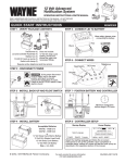
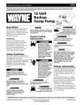
ESP45
Operating Instruction and Parts Manual
Operating Instructions and Parts Manual
Please read and save these instructions. Read carefully before attempting to assemble, install, operate or maintain the product described.
Protect yourself and others by observing all safety information. Failure to comply with instructions could result in personal injury and/or
property damage! Retain instructions for future reference.
Limited Warranty
24-Volt Backup
Sump
Pump
For two years from the date of purchase, Wayne Water Systems (“Wayne”) will repair or replace, at its option, for the
original purchaser any part or parts of its Sump Pumps or Water Pumps (“Product”) found upon examination by Wayne to be
defective in materials or workmanship. Please call Wayne (800-237-0987) for instructions or see your dealer. Be prepared to
provide the model and serial number when exercising this warranty. All transportation charges on Products or parts
submitted for repair or replacement must be paid by purchaser.
This Limited Warranty does not cover Products which have been damaged as a result of accident, abuse, misuse, neglect,
improper installation, improper maintenance, or failure to operate in accordance with Wayne’s written instructions.
THERE IS NO OTHER EXPRESS WARRANTY. IMPLIED WARRANTIES, INCLUDING THOSE OF MERCHANTABILITY AND
FITNESS FOR A PARTICULAR PURPOSE, ARE LIMITED TO TWO YEARS FROM THE DATE OF PURCHASE. THIS IS THE
EXCLUSIVE REMEDY AND ANY LIABILITY FOR ANY AND ALL INDIRECT OR CONSEQUENTIAL DAMAGES OR EXPENSES WHATSOEVER IS EXCLUDED.
Some states do not allow limitations on how long an implied warranty lasts, or do not allow the exclusions or limitations of
incidental or consequential damages, so the above limitations might not apply to you. This limited warranty gives you
specific legal rights, and you may also have other legal rights which vary from state to state.
In no event, whether as a result of breach of contract warranty, tort (including negligence) or otherwise, shall Wayne or its
suppliers be liable for any special, consequential, incidental or penal damages including, but not limited to loss of profit or
revenues, loss of use of the products or any associated equipment, damage to associated equipment, cost of capital, cost of
substitute products, facilities, services or replacement power, downtime costs, or claims of buyer’s customers for such
damages.
You MUST retain your purchase receipt along with this form. In the event you need to exercise a warranty claim, you MUST
send a copy of the purchase receipt along with the material or correspondence. Please call Wayne (800-237-0987) for return
authorization and instructions.
Description
The ESP45 is a battery operated back-up
sump pump. It does not replace a
regular pump. It is designed to provide
protection in the event household
electrical power fails or main pump fails.
Unpacking
Inspect this unit before it is used.
Occasionally, products are damaged
during shipment. If the pump or
components are damaged, return the
unit to the place of purchase for
replacement. Failure to do so could
result in serious injury or death.
DO NOT MAIL THIS FORM TO WAYNE. Use this form only to maintain your records.
Safety Guidelines
MODEL NO. _____________________ SERIAL NO. ________________________ INSTALLATION DATE _____________________
This manual contains information that
is very important to know and
understand. This information is
provided for SAFETY and to PREVENT
EQUIPMENT PROBLEMS. To help
recognize this information, observe the
following symbols.
ATTACH YOUR RECEIPT HERE
Danger indicates an
imminently
hazardous situation which, if not avoided,
will result in death or serious injury.
Warning indicates a
potentially
hazardous situation which, if not avoided,
could result in death or serious injury.
Caution indicates a
potentially
hazardous situation which, if not avoided,
may result in minor or moderate injury.
Notice indicates
important
information, that if not followed, may
cause damage to equipment.
General Safety
Information
All wiring must be
performed by a
qualified electrician.
CALIFORNIA PROPOSITION 65
This product or its
power cord may
contain chemicals known to the State of
California to cause cancer and birth
defects or other reproductive harm. Wash
hands after handling.
GENERAL SAFETY
Do not use to pump
flammable or explosive fluids
such as gasoline, fuel oil,
kerosene, etc. Do not use in a
flammable and/or explosive
atmosphere. Pump should only be used
to pump clear water. Fatal injury and/or
property damage could result.
If the basement has water or
moisture on the floor, do not
walk on wet area until all
power is turned off. If the shutoff box
is in the basement, call an electrician.
Remove pump and either repair or
replace. Failure to follow this warning
could result in fatal electrical shock.
Do not expose battery to
sparks or flames as an
explosion or fire could result.
Battery acid is corrosive.
Avoid spilling on skin or
clothing. Eye protection must
be worn when handling the battery.
A check valve must
be used on the
primary sump pump discharge.
A ground fault
circuit interrupter is required.
This pump must
only be used to
pump clear water. This pump is not
designed to handle effluent, salt
water, brine, laundry discharge or any
other application which may contain
caustic chemicals and/or foreign
materials. Pump damage may occur if
used in these applications and will void
warranty.
Pump Specifications
Power supply requirements . . . . . . . . . . . . . . . . . . . . . . . . . . . . . . . . . . . . . . . .120V, 60 Hz
Motor . . . . . . . . . . . . . . . . . . . . . . . . . . . . . . . . . . . . . . . . . . . Perminent Magnet DC Motor
Normal water removal . . . . . . . . . . . . . . . . . . . . . . . . . . . . . 2880 GPH @ 5 Feet @ 26V DC
Liquid temperature range . . . . . . . . . . . . . . . . . . . . . . . . . . . . . . . . . . . . . . . . 40°F to 120°F
Circuit requirements . . . . . . . . . . . . . . . . . . . . . . . . . . . . . . . . . . . . . . . . . . 5 amps AC (min)
Pump Dimensions . . . . . . . . . . . . . . . . . . . . . . . . . . . . . . . . . . . . . 11 in. high x 8 3/4 in. base
Pump run time . . . . . . . . . . . . . . . . . . . . . . . . . . . . . . . . . . . . . . . . . . . . . . . . . . . 15 Seconds
Pump Construction
Motor housing, volute, seal plate . . . . . . . . . . . . . . . . . . . . . . . . . . . . . . . . . . . . . Cast Iron
Impeller . . . . . . . . . . . . . . . . . . . . . . . . . . . . . . . . . . . . . . . . . . . . . . . . . . . . . . Thermoplastic
Shaft . . . . . . . . . . . . . . . . . . . . . . . . . . . . . . . . . . . . . . . . . . . . . . . . . . . . . . . . . Stainless Steel
Discharge . . . . . . . . . . . . . . . . . . . . . . . . . . . . . . . . . . . . . . . . . . . . . . . . . . . . . . . . 11/2 in. NPT
Float switch . . . . . . . . . . . . . . . . . . . . . . . . . . . . . . . . . . . . . . . . . . . . . . . . . . . . . . Reed Style
REMINDER: Keep your dated proof of purchase for warranty purposes! Attach it to this manual or file it for safekeeping.
www.waynepumps.com
© 2008 Wayne Water Systems
For parts, product & service information
visit www.waynepumps.com
8
353601-001 7/08
ESP45
Operating Instructions and Parts Manual
Battery Information
The system is designed to operate most
efficiently with sealed lead acid (SLA)
batteries. Deep cycle marine batteries
can also be used.
Sealed lead acid batteries cost slightly
more, but they can last longer. Wayne
offers a 40 amp hour battery WSB1240
and a 75 amp hour battery WSB1275.
The oversize battery case (included) will
accommodate two 12-volt SLA batteries
or two 12-volt deep cycle marine batteries
(up to a 27-frame size).
Retain blue foam pad to support Wayne
sealed lead-acid batteries. Use new,
identical batteries (from the same
manufacturer and of the same capacity).
When batteries wear out replace them as
a set. Chart 1 illustrates the expected
performance with various battery
combinations. Do not use batteries rated
below 40 amp hours.
Be certain that the area around the
batteries is well ventilated. Before
servicing the batteries, blow away
gasses by waving a piece of cardboard
near the batteries.
Dangerous
hydrogen gas can
be released from batteries while
charging. Sparks can ignite the gas in
an enclosed space. Wear safety goggles
when connecting batteries. Battery
connections should be made in a wellventilated area.
Working in the
vicinity of lead acid
batteries can be dangerous. Before
making connections or servicing the
batteries, read and follow instructions in
all applicable instruction manuals. To
reduce the risk of battery explosion,
follow the instructions in this manual
and those published by the battery
manufacturer, as well as those of any
other equipment used in the
surrounding area.
An assistant should be present or close
enough to come to your aid in the
event of an emergency. Have a reliable
source of fresh water and soap nearby
in case battery acid contacts clothing,
skin or eyes.
Wear eye and clothing protection when
working around lead acid batteries.
Avoid touching your eyes when
working around lead acid batteries.
If battery acid
contacts your
eye(s), flush with cold running water
for 10 minutes and seek immediate
medical attention. If acid contacts your
skin or clothing, wash immediately
with soap and water.
Never smoke or
allow a spark or
flame in the vicinity of the battery.
Avoid dropping
metal tools on the
battery posts because they may spark or
short-circuit the system or battery,
causing an explosion.
PS/BC Features
POWER CIRCUITS:
• Power Supply/Battery Charger (PS/BC)
monitors power availability and
automatically switches to battery
operation during power outage.
• Charger will run pump motor or charge
batteries when plugged into AC power
• Automatically charges the batteries
• Operates on 120 VAC and 24 VDC
(Using 2 batteries)
• The PS/BC can be left connected to
the batteries indefinitely
• The PS/BC is designed for the Wayne
Water Systems pump only, DO NOT
Use For Any Other Purpose
CHART 1 - STANDBY POWER
PUMPING CAPACITY
Amp Hours
Total Gallons
Per Battery
Pumped*
40.0
80.0
120.0
For Replacement Parts, call 1-800-237-0987
Please provide following information:
-Model number
-Serial number (if any)
-Part descriptions and number as shown in parts list
11,000
22,000
33,000
* Assumes the sump pump is lifting water 10’
SYSTEM WILL ALARM IF:
• You will hear a beeping alarm if
pump motor is running
• You will hear a continuous alarm if the
pump fuse on front panel is blown
• You will hear a continuous alarm if
the battery voltage drops below 21.6
NOTE: The alarm must be on for the
mute function to activate.
7
2
LIGHTS:
• Green Light indicates AC power is
available
• Yellow Light indicates battery is
connected correctly
• Red Light is on when battery voltage
is low or if the pump motor fuse on
the front panel is blown
PUMP:
• The pump will turn on when the
float switch rises. The pump motor
will keep running for 15 seconds
after the float drops
(Black)
Negative
Battery Cable
1
6
PS/BC
(Red)
Positive Battery Cable
5
Ref.
No. Description
B
Qty.
Pump
06710
1
2
PS/BC (power supply/ battery charger)
30260-001
1
3
Impeller assembly
29884-001
1
4
Wear ring
28183-001
1
5
Impeller plate
15958
1
6
Seal
21203-001
1
Float Kit, ESP45
60120-001
1
4
A
12V
Battery
Part
Number
1
*7
Jumper Wire
12V
Battery
Address parts correspondence to:
Wayne Water Systems
101 Production Drive
Harrison, OH 45030 U.S.A.
* Service Part Only
3
Figure 1 - Battery connection: two 12-volt batteries equals a 24-volt battery
www.waynepumps.com
www.waynepumps.com
2
7
ESP45
Operating Instructions and Parts Manual
Maintenance
(Continued)
3. Inspect the terminals and clamps
for corrosion and tightness. Clean
and tighten as required.
4. Unplug the main pump and fill sump
with water until back up pump turns
on. Repeat process two times to be
sure pump is operating normally.
5. If pump operates normally, plug
PS/BC into wall outlet, turn on main
pump. If pump fails to operate
normally, see Troubleshooting guide
and correct problem. Repeat step 5.
Pump Installation
Installation of this
unit may take
several hours. Before disabling your
main pump, have ready an appropriate
means of evacuating the sump.
Symptom
Possible Cause(s)
Corrective Action
Pump won’t run
1. Connections not secure
2. Low or defective battery
3. Float switch stuck
1. Check all connections
2. Check battery and replace if low or defective
3. Make sure nothing is interfering with operation of switch
Pump Installation
The ESP45 can be installed as a back up
system with a separate dedicated
discharge line (Method 1), or tied into
an existing sump pump line (Method 2).
4. Defective or blown fuse
4. Check internal fuse located on the PS/BC. Pull the charger from
the wall outlet and remove. If the fuse is blown, replace it with
an automotive type fuse of the same amp ratio.
Unplug the existing
AC pump. Failure to
follow this warning could result in fatal
electrical shock.
1. Check battery and replace if low or defective
2. Unplug pump, volute, and check to see if impeller is free to turn.
If impeller is locked, remove the obstruction. Reassemble pump
and reconnect
1. Verify that the existing AC pump is
in good working order. If the AC
pump is questionable, it is typically
recommended that the unit be
replaced with a 1/3 or 1/2 HP pump.
2. Remove any silt or accumulated
debris from the sump pit and
surrounding area.
Pump runs but
pumps very little
or no water
1. Defective battery
2. Impeller is locked
1. Check valve missing or improperly
installed
2. Obstruction in discharge pipe
or pump inlet
3. Discharge pipe length and/or
height exceeds capacity of pump
4. Low or defective battery
1. Check to make sure check valves installed between primary
pump discharge and Backup Sump Pump are functioning
properly
2. Check for obstruction and clear if necessary
3. If discharge is too high, a separate line may be required with a
lower discharge height
4. Check battery and replace if low or defective
Pump cycles too
frequently
1. Check valve problem
No yellow light
1. Battery connection problem
1. Verify battery connection is correct
Red light is on
with alarm
1. Blown pump fuse
2. Low battery voltage
1. Check fuse and replace with a fuse of same rating and size
2. Check battery voltage. PS/BC will not charge batteries with a
combined voltage of 21.6 VDC or less
1. Check to make sure check valves installed between primary
pump discharge and Backup Sump Pump are functioning
properly
Method 1 (Preferred)
1. Locate the ESP45 on a solid, level
surface in the sump pit. Do not
place the pump on a loose or sandy
surface. Small stones or sand may
damage the pump resulting in
potential pump failure.
2. This pump has a 11/2” NPT discharge.
If a 11/4” discharge pipe is desired,
an adapter (not included) will be
necessary. Smaller diameter piping
will reduce pump flow, rate and
performance.
Check Valve
(See Step 6)
PS/BC
Batteries
11/4” or
11/2”
PVC Pipe
Battery
Box
ESP45
Pump
Existing Pump
Figure 2 - Method 1
5. Place the pump with the 4’ section of
PVC pipe on a solid, level surface in
the sump pit on an elevated surface.
6. Attach a rubber check valve (sold
separately) to the top of the
discharge pipe. This will allow the
pump or check valve to be removed
easily for servicing.
7. Check valve is required for effective
operation of system.
3. Cut a 4’ section of 11/4" or 11/2"
diameter rigid PVC pipe. Cement
11/4" pipe to a threaded fitting.
Cement 11/4" pipe into pipe
coupling. Attach 11/4" pipe section
to the ESP45 discharge adapter.
NOTE: Check valves can be placed
directly in the pump discharge if
desired. However, for ease of
disassembly, it is recommended that
check valves be placed above the sump
as shown in Figure 2.
4. Screw on to pump discharge.
The remainder of the discharge pipe
installation will vary depending on
individual circumstances. Using sound
plumbing practices, route the
discharge pipe to an exterior wall by
the shortest path. Keep turns to a
minimum because they reduce flow
output of the pump. The pipe that
exits the building structure should be
Be careful not to
strip or cross thread
plastic fittings or check valves. Flex hose
is not recommended. Rigid PVC or metal
pipe is required for a permanent
installation.
Slope
Pipe
Down
Ridgid
PVC
Pipe
1. Turn power to main pump off.
2. Pump must be installed using 11/4”
or 11/2” rigid PVC piping.
Troubleshooting Chart
Motor hums but
pump won’t run
Floor
Joist
www.waynepumps.com
sloped downward so that water will
not freeze in the pipe.
When installing the separate discharge
pipe, drill through the outside wall with
appropriate drilling equipment. Seal the
hole to prevent water from entering.
Method 2
If a separate, dedicated discharge is
not possible as in Method 1, the ESP45
pump can be tied in to the ACoperated pump’s discharge pipe by
installing a “Y” connector. Two check
valves will be required.
1. Locate the ESP45 on a solid, level
surface in the sump pit. Do not
place the pump on a loose or sandy
surface. Small stones or sand may
damage the pump resulting in
potential pump failure.
2. This pump has a 11/2” NPT discharge.
If a 11/4” discharge pipe is desired,
an adapter (not included) will be
necessary. Smaller diameter piping
will reduce pump flow, rate and
performance.
www.waynepumps.com
6
3
Operating Instructions and Parts Manual
ESP45
Pump Installation
PS/BC Installation
(Continued)
(Continued)
3. A check valve will be required in
the discharge line of BOTH the
Main AC pump and the ESP45
pump to prevent recirculation of
water into the sump pit. System will
not function without two check
valves.
4. Cut a 4’ section of 11/4" or 11/2"
diameter rigid PVC pipe. Cement
11/2" pipe to a threaded fitting.
Cement 11/4" pipe into pipe
coupling. Attach 11/4" pipe section
to the ESP45 discharge adapter.
Floor
Joist
“Y”
Connector
45°
Elbow
PS/BC
Rigid PVC
Pipe
Check Valve
(See Step 10)
Batteries
Be careful not to
strip or cross thread
plastic fittings or check valves. Flex hose
is not recommended. Rigid PVC or metal
pipe is required for a permanent
installation.
NOTE: Check valves can be placed
directly in the pump discharge if
desired. However, for ease of
disassembly, it is recommended that
check valves be placed above the sump
as shown in Figure 3.
The remainder of the discharge pipe
installation will vary depending on
individual circumstances. Using sound
plumbing practices, route the
discharge pipe to an exterior wall by
the shortest distance.
2. Wave cardboard over batteries to
blow away any gas that may be
present.
3. Connect jumper wire between
batteries as shown on Figure 1.
4. Connect power wires from PS/BC to
battery terminals as shown in
Figure 1. Connect the red wire to
the unconnected positive terminal
of battery A and then connect the
black wire to the unconnected
negative terminal of battery B. The
yellow light should now be on.
5. Screw on to pump discharge.
6. Place the pump with the 4’ section
of PVC pipe on the sump floor or
on an elevated surface if required.
7. Attach a rubber check valve (sold
separately) to the top of the
discharge pipe. This will allow the
pump or check valve to be removed
easily for servicing.
8. Duplicate the discharge piping
arrangement for the primary AC
pump if the existing discharge line
has to be adjusted to accommodate
a second pump.
9. Glue a 45º elbow to the short pipe
on the ESP45 pump. Glue a “Y”
adapter to the short pipe on the
existing pump, as shown in
illustration for Method 2.
10. Glue a short piece of PVC pipe
between the 45º elbow and the “Y”.
1. Place battery box within six feet of
the sump and a 115 VAC separately
fused outlet. The outlet must be
protected by a ground fault circuit
interrupter (GFCI). The area must also
be clean, dry and well-ventilated.
Battery
Box
ESP45
Pump
Existing Pump
Figure 3 - Method 2
Methods 1 and 2
Install float switch at least 10”-12”
above bottom of sump pit so that
backup unit turns on only when the
water level is higher than the normal
“on” level for main pump. Use the hose
clamps provided to secure the switch to
the discharge pipe. Make sure power
wires and hose clamp ends do not
interfere with float switch, pump inlet,
or main pump operation. Backup pump
must not be allowed to run dry.
PS/BC Installation
Use Power Supply/
Battery Charger
(PS/BC) indoors, in a well-ventilated
area. Do not expose PS/BC to rain or
snow. Do not use an extension cord. Do
not disassemble PS/BC. Be sure PS/BC
ventilation holes are unobstructed. If
PS/BC is dropped or damaged, do not
operate; return to manufacturer for
service.
Risk of electrical
shock! Use a GFCI
(Ground Fault Circuit Interrupter)
receptacle to reduce the risk of fatal
electrical shock. Grounded receptacle must
be rated for at least 5 amps.
Always disconnect
AC power and
remove pump fuse before connecting or
disconnecting battery.
5. Plug the pump and then the float
into the PS/BC. The connections are
marked.
6. Test pump operation by filling the
sump with water while the main
pump is unplugged. If the pump
operates properly, plug the PS/BC
into the GFCI protected outlet to
begin charging the battery.
1. Select a suitable position on the floor
near the sump pit to place the battery
case. Be certain that the PS/BC power
cord will reach AC power, and that
the sump pump power cord will reach
the PS/BC. Make sure the battery case
vent holes are unobstructed.
NOTE: Protect electrical cord from sharp
objects, hot surfaces, oil and chemicals.
Avoid kinking the cord and replace
damaged components immediately.
ELEVATE PS/BC BY MOUNTING ON
WALL OR SETTING ON A SHELF. SLOTS
IN THE BACK SIDE OF PS/BC ARE
AVAILABLE FOR WALL MOUNTING.
Always disconnect the power
source before attempting to
install, service, relocate or
maintain the pump. Never touch sump
pump, pump motor, water or discharge
piping when pump is connected to
electrical power. Never handle a pump
or pump motor with wet hands or when
standing on wet or damp surface or in
water. Fatal electrical shock could occur.
Control Box Installation
If cables are
reversed, damage
to the PS/BC or battery could result,
and warranty will be void.
Dangerous hydrogen gas can be
released from batteries while charging.
Sparks can ignite the gas in an
enclosed space. Wear safety goggles
when connecting batteries. Battery
connections should be made in a wellventilated area.
Operation
Risk of electrical shock! Use a
GFCI receptacle to reduce the
risk of fatal electrical shock.
Cutting the cord or plug will void the
warranty and make the pump inoperable.
LIGHT
CHART 2 - PS/BC STATUS LIGHTS
ON WHEN
ACTION REQUIRED
Red
Low Voltage or Blown Fuse
Check Fuse or
Replace Batteries
Yellow
Battery OK
None
Green
AC power on
None
1. After installation, the backup pump
will start when the water level rises
above the depth that the primary
pump should start.
2. The PS/BC has a DC charger designed
to shorten the recharging time of
your battery, and to prevent
overcharging. In addition, the
control box has a time delay which
keeps the pump from repeated,
short cycles when it shuts off. This
time delay feature will allow the
pump to run 15 seconds after the
switch reaches the off position.
Working in the
vicinity of lead acid
batteries can be dangerous. Before making
connections or servicing the batteries, read
and follow instructions in all applicable
instruction manuals. To reduce the risk of
battery explosion, follow the instructions
in this manual and those published by the
battery manufacturer, as well as those of
any other equipment used in the
surrounding area.
Maintenance
If battery acid contacts your eye(s),
flush with cold running water for 10
minutes and seek immediate medical
attention. If acid contacts your skin or
clothing, wash immediately with soap
and water.
Unplug main AC pump and the
charger. Risk of electrical
shock!
Never smoke or allow a spark or flame
in the vicinity of the battery.
Always disconnect the
electrical supply before
attempting to install, service,
relocate or per-form any maintenance. If
the power source is out of sight, lock and
tag in the open (off) position to prevent
unexpected power application. Failure to
do so could result in fatal electrical
shock. Only qualified electricians should
repair this unit. Improper repair could
result in fatal electrical shock.
Once a month,
check the condition
of the battery. In order to review the
battery condition, follow the steps that
are listed below:
BATTERIES
Dangerous
hydrogen gas can
be released from batteries while
charging. Sparks can ignite the gas in
an enclosed space. Wear safety goggles
when connecting batteries. Battery
connections should be made in a wellventilated area.
Avoid dropping metal tools on the
battery posts because they may spark
or short-circuit the system or battery,
causing an explosion.
Follow battery manufacturer’s
maintenance procedures and
schedules. Be certain that the area
around the batteries is well ventilated.
Before servicing the batteries, blow
away gasses by waving a piece of
cardboard near the batteries.
1. Unplug the PS/BC.
2. For batteries with top caps that can
be removed, the electrolyte level
should be checked and filled to
manufacturer’s specifications. The
charge for each cell should be
checked with a hydrometer. A
specific gravity of 1.265 indicates
the battery is at full charge. If the
specific gravity of any of the cells
varies more than .050, the battery
should be replaced.
NOTE: An inexpensive hydrometer
can be purchased at an automotive
parts dealer.
www.waynepumps.com
www.waynepumps.com
4
5