1
Manual de Instrucciones de Operación y Piezas
ESP25
Operating Instruction and Parts Manual
Please read and save these instructions. Read carefully before attempting to assemble, install, operate or maintain the product described.
Protect yourself and others by observing all safety information. Failure to comply with instructions could result in personal injury and/or
property damage! Retain instructions for future reference.
Garantía Limitada
Durante un año a partir de la fecha de compra, Wayne Water Systems ("Wayne") reparará o reemplazará para el comprador
original, según lo que decida, cualquier pieza o piezas de su Juego para estanque, Bombas de resumideros, Bombas de agua
("Producto") que después de un examen Wayne encuentre que tenían defectos en su material o mano de obra. Sírvase
llamar a la compañía Wayne (800-237-0987, desde EUA) para recibir instrucciones al respecto o comuníquese con el
distribuidor más cercano a su domicilio. Para hacer reclamos bajo esta garantía deberá suministrarnos el número del modelo y
el número de serie del producto. El comprador será responsable de pagar todos los gastos de flete para enviar las piezas o el
Producto para que sean reparados o reemplazados.
Esta Garantía Limitada no cubre los daños que sufra el Producto debido a accidentes, abusos, usos inadecuados, negligencia,
instalación incorrecta, mantenimiento inadecuado o haberse utilizado sin seguir las instrucciones escritas suministradas por la
compañía Wayne.
NO EXISTEN OTRAS GARANTIAS EXPRESAS. LAS GARANTIAS IMPLICITAS INCLUYENDO GARANTIAS EN RELACION AL
MERCADEO O USOS ESPECIFICOS ESTAN LIMITADAS A UN AÑO A PARTIR DE LA FECHA DE COMPRA. ESTA ES LA
UNICA GARANTIA DISPONIBLE Y TODAS LAS REPONSABILIDADES CIVILES, DIRECTAS O INDIRECTAS, O GASTOS POR
DAÑOS INDIRECTOS O CONSECUENTES QUEDAN EXCLUIDOS.
Algunos estados no permiten que se establezcan límites en la duración de las garantías implicitas o no permiten que se
excluyan ni se establezcan límites en los daños por incidentes o consecuencias, por lo tanto los límites antes mencionados
podrían ser no válidos. Esta Garantía Limitada le otorga derechos legales especificos, y usted también puede tener otros
derechos que varian de un Estado a otro.
En ningún caso, bien sea por ruptura del contrato de la garantía, responsabilidad civil (incluyendo negligencia) u otra causa,
Wayne o sus distribuidores serán responsables pon daños especiales, consecuentes ni circunstanciales ni penales, incluyendo,
pero no limitados a la pérdida de ganancias, pérdida de uso del producto o equipos asociados, daños a equipos asociados,
costos de capitales, costos para substituir productos, costos para substituir o reemplazar servicios, costos por pérdida de
productividad, o reclamos de clientes del comprador por dichos daños.
DEBE conservar el recibo de compra con esta garantía. En caso de que necesite hacer un reclamo bajo esta garantía, DEBERA
enviarnos una copia del recibo junto con el material o correspondencia. Sírvase comunicarse con la compañía Wayne (800-2370987, en EUA) para recibir autorización e instrucciones para enviar el producto.
NO ENVIE ESTA GARANTIA A WAYNE. Use este documento sólo para mantener sus records.
NO. DEL MODELO _____________________ NO. DE SERIE ________________________ FECHA DE INSTALACION __________________
ANEXE SU RECIBO AQUI
12 Volt
Backup
Sump Pump
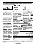
Description
The ESP25 is a battery operated backup sump pump. It does not replace a
regular pump. It is designed to provide
protection in the event household
electrical power fails.
Unpacking
Inspect this unit before it is used.
Occasionally, products are damaged
during shipment. If the pump or
components are damaged, return the
unit to the place of purchase for
replacement. Failure to do so could
result in serious injury or death.
Safety Guidelines
This manual contains information that is
very important to know and
understand. This information is provided
for SAFETY and to PREVENT EQUIPMENT
PROBLEMS. To help recognize this
information, observe the following
symbols.
!
DANGER
Danger indicates an imminently
hazardous situation which, if not
avoided, will result in death or serious
injury.
! WARNING
Warning indicates a potentially
hazardous situation which, if not
avoided, could result in death or serious
injury.
!
CAUTION
Caution indicates a potentially
hazardous situation which, if not
avoided, may result in minor or
moderate injury.
BATTER
Y BACKU
P SUMP
PUMP
RY
LIA
UXI
Sump A
Pump
! WARNING
NOTICE
Notice indicates important information,
that if not followed, may cause damage
to equipment.
General Safety
Information
!
DANGER
Do not use to pump
flammable or explosive
fluids such as gasoline,
fuel oil, kerosene, etc. Do
not use in a flammable
and/or explosive
atmosphere. Pump should
only be used to pump
clear water. Fatal injury
and/or property damage
could result.
!
DANGER
If the basement has
water or moisture on the
floor, do not walk on wet
area until all power is
turned off. If the shutoff
box is in the basement,
call an electrician.
Remove pump and either
repair or replace. Failure
to follow this warning
could result in fatal
electrical shock.
! WARNING
All wiring must be performed by a
qualified electrician.
! WARNING
Do not expose battery to
sparks or flames as an
explosion or fire could
result.
yyy
;;;
;;;
yyy
;;;
yyy
Battery acid is corrosive.
Avoid spilling on skin or
clothing. Eye protection
must be worn when
handling the battery.
! WARNING
A check valve must be used on the
primary sump pump discharge.
! WARNING
A ground fault circuit interrupter is
required.
NOTICE
This pump must only be used to pump
clear water. This pump is not designed
to handle effluent, salt water, brine,
laundry discharge or any other
application which may contain caustic
chemicals and/or foreign materials.
Pump damage may occur if used in
these applications and will void
warranty.
Battery Information
The system is designed to operate most
efficiently with sealed lead acid (SLA)
batteries. Deep cycle marine batteries
or automotive style batteries can also
be used.
Sealed lead acid batteries cost slightly
more, but they can last longer. Among
the manufacturers of sealed lead acid
batteries are Hawker, Panasonic,
PowerSonic, Yuasa and Eagle Picher.
The oversize battery case (included) will
accommodate a 12-volt SLA battery or
a 12-volt deep cycle marine battery (up
to a 27-frame size).
REMINDER: Keep your dated proof of purchase for warranty purposes! Attach it to this manual or file it for safekeeping.
8 Sp
© 2003 Wayne Water Systems
For parts, product & service information
visit www.waynepumps.com
352200-001 9/03
Operating Instructions And Parts Manual
Battery Information
(Continued)
Be certain that the area around the
batteries is well ventilated. Before
servicing the batteries, blow away
gasses by waving a piece of cardboard
near the batteries.
!
DANGER
Dangerous hydrogen gas can be
released from batteries while charging.
Sparks can ignite the gas in an
enclosed space. Wear safety goggles
when connecting batteries. Battery
connections should be made in a wellventilated area.
!
DANGER
Working in the vicinity of lead acid
batteries can be dangerous. Before
making connections or servicing the
batteries, read and follow instructions
in all applicable instruction manuals. To
reduce the risk of battery explosion,
follow the instructions in this manual
and those published by the battery
manufacturer, as well as those of any
other equipment used in the
surrounding area.
ESP25
! WARNING
!
Avoid dropping metal tools on the
battery posts because they may spark
or short-circuit the system or battery,
causing an explosion.
Installation
NOTICE
Installation of this unit may take
several hours. Before disabling your
main pump, have ready an appropriate
means of evacuating the sump.
1. Turn power to main pump off.
2. Pump must be installed using 11/4”
or 11/2” rigid PVC piping.
Pump Installation
The ESP25 can be installed as a back up
system with a separate dedicated
discharge line (Method 1), or tied into
an existing sump pump line (Method 2,
page 3).
An assistant should be present or close
enough to come to your aid in the
event of an emergency. Have a reliable
source of fresh water and soap nearby
in case battery acid contacts clothing,
skin or eyes.
Ridgid
PVC
Pipe
Dirección para correspondencia sobre repuestos:
Wayne Water Systems
100 Production Drive
Harrison, OH 45030 U.S.A.
7
1
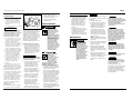
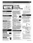
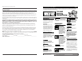
Method 1 (Preferred)
1. Locate the ESP25 on a solid, level
surface in the sump pit. Do not
place the pump on a loose or sandy
surface. Small stones or sand may
damage the pump resulting in
potential pump failure.
2. The pump has a 1-1/4” NPT
discharge adapter. If a 1-1/2”
discharge pipe is desired, glue pipe
coupling to outside of adapter .
Smaller diameter piping will reduce
pump flow, rate and performance.
2
5
4
6
Slope
Pipe
Down
Check Valve
(See Step 6)
Charger
! WARNING
Never smoke or allow a spark or flame
in the vicinity of the battery.
Sírvase proporcionar la siguiente información:
- Número del modelo
- Número de serie (de haberlo)
- Descripciones y número de piezas, tal como
aparecen en la lista de piezas.
3
No. de
Ref.
Avoid touching your eyes when
working around lead acid batteries.
! WARNING
1. Verify that the existing AC pump is
in good working order. If the AC
pump is questionable, it is typically
recommended that the unit be
replaced with a 1/3 or 1/2 HP pump.
2. Remove any silt or accumulated
debris from the sump pit and
surrounding area.
Para Ordenar Repuestos, Sírvase llamer al Concesionario
más Cercano a su Domicilio
Floor
Joist
Wear eye and clothing protection
when working around lead acid
batteries.
If battery acid contacts your eye(s),
flush with cold running water for 10
minutes and seek immediate medical
attention. If acid contacts your skin or
clothing, wash immediately with soap
and water.
DANGER
Unplug the existing AC pump. Failure
to follow this warning could result in
fatal electrical shock.
Check Valve
(See Step 6)
1-1/4” or
1-1/2”
PVC Pipe
Descripción
Número
de pieza
1
Banda para amarrar
17182-003
4
2
Adaptador
31042-001
1
3
Cargador
30221-001
1
4
Caja de control
30222-001
1
5
Tornillo - caja de control
16119-002
4
6
Bomba
60089-001
1
7
Interruptor/ flotante
30206-001
1
Battery Box
Pipe Adapter
ESP25 Pump
Existing Pump
Figure 1 - Method 1
www.waynepumps.com
2
Ctd.
7 Sp
Manual de Instrucciones de Operación y Piezas
ESP25
Installation
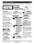
Method 2
Problema
Posible(s) Causa(s)
Acción Correctiva
(Continued)
La bomba no
funciona
1. Conexiones flojas
2. Batería baja o defectuosa
3. El interruptor de flotador no puede
subir y bajar como es necesario
4. Fusible defectuoso o quemado
1. Revise todas las conexiones
2. Revise la batería y reemplácela si está baja o defectuosa
3. Compruebe que el cordón flexible del interruptor de flotador
tiene longitud suficiente para permitir que la bomba funcione
4. Revise el fusible interno ubicado dentro de la caja de control.
Desconecte el cargador del tomacorrientes de la pared y retire
el fusible. Si está quemado, cámbielo por un fusible tipo automotor de 20 amperios
3. Cut a 4’ section of 1-1/4” or 1-1/2”
diameter rigid PVC pipe. Cement
1-1/4” pipe to a threaded fitting.
Cement 1-1/2” pipe into pipe
coupling. Attach 1-1/4” pipe
section to the ESP25 discharge
adapter.
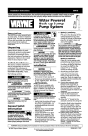
If a separate, dedicated discharge is
not possible as in Method 1, the ESP25
pump can be tied in to the ACoperated pump’s discharge pipe by
installing a “Y” connector. Two check
valves will be required.
Guía de diagnóstico de averías
El motor zumba,
pero la bomba no
funciona
1. Batería defectuosa
2. El impulsor está bloqueado
La bomba
funciona pero
bombea poca o
nada de agua
1. Revise la válvula que falta o que
está mal instalada
Los ciclos de la
bomba son muy
frecuentes
2. Obstrucción en el tubo de descarga
3. La longitud y/o altura del tubo de
descarga excede la capacidad de la
bomba
4. Batería baja o defectuosa
1. La longitud del cconector del
flotante en el interruptor de
flotador es muy corta
2. Revise los problemas de válvulas
1. Revise la batería y reemplácela si está baja o defectuosa
2. Desconecte la bomba, retire la rejilla y revise para ver si el
impulsor puede girar libremente. Si el impulsor está bloqueado,
retire los 8 tornillos en la parte inferior de la bomba para
liberar la caja que cubre el impulsor. Retire la obstrucción.
Vuelva a armar la bomba y vuelva a conectar.
1. Revise para asegurarse de que las válvulas de retención
instaladas entre la bomba primaria y la bomba de respaldo para
sumideros estén funcionando adecuadamente.
2. Revise si hay obstrucción y remuévala si es necesario
3. Si la línea de descarga está muy alta, tal vez necesitará instalar
una línea de descarga adicional a una altura inferiro
4. Revise la batería y cámbiela si está baja o defectuosa
1. La longitud del conector del flotante debe ser de 5,1 cm por lo
menos. Ajústelo si es necesario
PRECAUCION: Cerciórese de que el conector del flotante se
puede mover sin obstrucciones
2. Revise para asegurarse de que las válvulas de retención
instaladas entre la bomba primaria y la bomba de respaldo para
sumideros estén funcionando adecuadamente.
4. Screw on to pump discharge.
NOTICE
Be careful not to strip or cross thread
plastic fittings or check valves. Flex
hose is not recommended. Rigid PVC or
metal pipe is required for a permanent
installation.
5. Place the pump with the 4’ section
of PVC pipe on a solid, level surface
in the sump pit on an elevated
surface.
6. Attach a rubber check valve (sold
separately) to the top of the
discharge pipe. This will allow the
pump or check valve to be
removed easily for servicing.
1. Locate the ESP25 on a solid, level
surface in the sump pit. Do not
place the pump on a loose or sandy
surface. Small stones or sand may
damage the pump resulting in
potential pump failure.
2. The pump has a 1-1/4” NPT
discharge adapter. If a 1-1/2”
discharge pipe is desired, glue pipe
coupling to outside of adapter.
Smaller diameter piping will reduce
pump flow, rate and performance.
3. A check valve will be required in
the discharge line of BOTH the
Main AC pump and the ESP25
pump to prevent recirculation of
NOTE: Check valves can be placed
directly in the pump discharge if
desired. However, for ease of
disassembly, it is recommended that
check valves be placed above the sump
as shown in Figure 1.
The remainder of the discharge pipe
installation will vary depending on
individual circumstances. Using sound
plumbing practices, route the
discharge pipe to an exterior wall by
the shortest path. Keep turns to a
minimum because they reduce flow
output of the pump. The pipe that
exits the building structure should be
sloped downward so that water will
not freeze in the pipe.
When installing the separate discharge
pipe, drill through the outside wall
with appropriate drilling equipment.
Seal the hole to prevent water from
entering.
water into the sump pit. System will
not function without two check
valves.
4. Cut a 4’ section of 1-1/4” or 1-1/2”
diameter rigid PVC pipe. Cement
1-1/4” pipe to a threaded fitting.
Cement 1-1/2” pipe into pipe
coupling. Attach 1-1/4” pipe section
to the ESP25 discharge adapter.
5. Screw on to pump discharge.
NOTICE
Be careful not to strip or cross thread
plastic fittings or check valves. Flex
hose is not recommended. Rigid PVC or
metal pipe is required for a permanent
installation.
6. Place the pump with the 4’ section
of PVC pipe on the sump floor or
on an elevated surface if required.
7. Attach a rubber check valve (sold
separately) to the top of the
discharge pipe. This will allow the
pump or check valve to be removed
easily for servicing.
Floor
Joist
“Y”
Connector
45°
Elbow
Rigid PVC
Pipe
Charger
Check Valve
(See Step 10)
Check
Valve
(See
Step 10)
Battery Box
Float Tied to Discharge Line
ESP25 Pump
Existing Pump
Figure 2 - Method 2
6 Sp
3
www.waynepumps.com
Operating Instructions And Parts Manual
ESP25
Installation
(Continued)
8. Duplicate the discharge piping
arrangement for the primary AC
pump if the existing discharge line
has to be adjusted to accommodate
a second pump.
9. Glue a 45º elbow to the short pipe
on the ESP25 pump. Glue a “Y”
adapter to the short pipe on the
existing pump, as shown in
illustration for Method 2.
10. Glue a short piece of PVC pipe
between the 45º elbow and the
“Y”.
NOTE: Check valves can be placed
directly in the pump discharge if
desired. However, for ease of
disassembly, it is recommended that
check valves be placed above the sump
as shown in Figure 2.
The remainder of the discharge pipe
installation will vary depending on
individual circumstances. Using sound
plumbing practices, route the
discharge pipe to an exterior wall by
the shortest distance.
Methods 1 and 2
The ESP25 float switch should be
adjusted so that the back up unit turns
on once the water level is higher than
the normal “ON” level for the main
pump. Use the wire ties provided to
secure the float switch. Make sure
power wires do not interfere with float
switch, pump inlet or main pump
operation. The backup pump must not
be allowed to run dry.
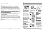
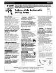
Control Box Installation
1. Attach control box to the side of
battery box as shown in Figure 3.
Place battery in box, attach red
cable to positive battery post and
black cable to negative post. Put lid
on box.
!
CAUTION
If cables are reversed, damage to the
control box or battery could result, and
warranty will be void.
2. Place battery box within six feet of
the sump and a 115 VAC separately
fused outlet. The outlet must be
www.waynepumps.com
Battery box bottom
Control
box screw
Lead Wires
BATTERY
BACKUP
SUMP PUM
P
RY
ILIA
AUX
Sump
Pump
Control box
Figure 3
protected by a ground fault circuit
interrupter (GFCI). The area must
also be clean, dry and wellventilated.
3. Plug the float switch, pump and
charger into the control box. The
connections are marked on the
control box.
4. Test pump operation by filling the
sump with water while the main
pump is unplugged. If the pump
operates properly, plug the charger
into the GFCI protected outlet to
begin charging the battery.
5. Protect electrical cord from sharp
objects, hot surfaces, oil and
chemicals. Avoid kinking the cord
and replace damaged components
immediately.
Operation
!
DANGER
Always disconnect the
power source before
attempting to install,
service, relocate or
maintain the pump.
Never touch sump pump,
pump motor, water or
discharge piping when
pump is connected to
electrical power. Never
handle a pump or pump
motor with wet hands or
when standing on wet or
damp surface or in water.
Fatal electrical shock
could occur.
!
DANGER
Risk of electrical shock!
Use a GFCI receptacle to
reduce the risk of fatal
4
electrical shock. Cutting
the cord or plug will void
the warranty and make
the pump inoperable.
1. After installation, the backup pump
will start when the water level rises
above the depth that the primary
pump should start.
2. The control box has a DC charger
designed to shorten the recharging
time of your battery, and to
prevent overcharging. In addition,
the control box has a time delay
which keeps the pump from
repeated, short cycles when it shuts
off. This time delay feature will
allow the pump to run two to three
seconds after the switch reaches the
off position.
3. The control box contains a multicolored indicator light. When AC
power is present, the light will
indicate the charging state, and not
reflect actual battery voltage,
particularly with a defective
battery. In order for the indicator
light to provide an accurate
reading, steps “a” through “d”
must be followed.
!
DANGER
Unplug main AC pump
and the charger. Risk of
electrical shock!
a. After main AC pump and
charger are unplugged, a power
off alert tone will sound for 30
seconds.
b. Lift and release the float switch
to activate the backup pump.
c. When the pump stops, read the
test light:
Green: Indicates battery is
charged.
Yellow: Voltage is low,
indicating battery is partially
charged.
Red: Battery is completely
discharged or defective.
d. Plug in charger and main AC
pump.
When AC power is out, and when
pump has been running, the light
will indicate battery status.
Funcionamiento
(Continuación)
3. La caja de controles contiene una
luz multicolor indicadora. Si se
utiliza corriente alterna, la luz le
indicará que se está cargando la
unidad, pero no le indicará el
voltaje de la batería, especialmente
si la batería está dañada. Para que
la luz le indique información
correcta debe seguir los pasos de
“a” a “d” .
!
PELIGRO
Desconecte la bomba de
CA principal y el cargador.
¡Riesgo de choque
eléctrico!
a. Después de haber desconectado
la bomba de CA principal y el
cargador, sonará un tono de alerta
de apagado de energía durante 30
segundos.
b. Levante y suelte el interruptor de
flotador para activar la bomba de
respaldo.
c. Cuando la bomba deje de operar
vea las luces multicolores:
Verde: Le indica que la batería
está cargada.
Amarilla: Voltaje es bajo, la
batería sólo está parcialmente
cargada.
Roja: La batería está
totalmente descargada o
dañada.
d. Conecte la bomba principal y el
cargador al tomacorrientes.
Si la corriente alterna está apagada,
mientras la bomba está
funcionando, la luz le indicará la
carga de la batería.
4. Al escuchar un sonido cuando la luz
roja se enciende le indica que
necesita revisar o reemplazar la
batería. El voltaje sólo le indica la
condición de la batería pero no le
indica el estado en que se
encuentra. Vea la sección de
Mantenimiento donde se le indica
como evaluar el estado de la
batería.
5. Un silbido de 30 segundos le
indicará cuando se interrumpa el
suministro de energía. La unidad
comenzará a funcionar
automáticamente al comenzar el
suministro de energía. Cada vez que
la unidad comience a funcionar
escuchará un silbido de 30
segundos.
Mantenimiento
!
tomacorriente de pared y encienda
la bomba principal. Si la bomba deja
de operar normalmente, vea la guía
de Detección de fallas y corrija el
problema. Repita el paso No. 5.
BATERÍAS
PELIGRO
Siempre desconecte el
suministro eléctrico antes
de intentar instalar, dar
servicio, reubicar o ejecutar
cualquier mantenimiento. Si
la fuente de poder no está
a la vista, bloquéela y
márquela en posición
abierta (apagada) para
impedir la aplicación
inesperada de energía
eléctrica. Si no se cumple
con esta advertencia,
podría provocarse un
choque eléctrico de
consecuencias fatales. Sólo
electricistas calificados
deben reparar esta unidad.
Una reparación inadecuada
podría ocasionar un choque
eléctrico fatal.
AVISO
Revise la condición de la batería una vez
al mes. Para revisar el estado de la
batería, siga los pasos que se enumeran
a continuación:
1. Desconecte el cargador de pared.
2. En las baterías con tapones
superiores removibles, se debe
comprobar el nivel electrolítico y
mantenerlo de conformidad con los
lineamientos impartidos por el
fabricante. La carga para cada pila
se debe verificar con un hidrómetro.
Una gravedad específica de 1,265
indica que la batería está con carga
completa. Si la gravedad específica
de cualquiera de las pilas varía en
más de 0,050, la batería debe ser
reemplazada.
3. Inspeccione los bornes y
abrazaderas para determinar si hay
corrosión y si están ajustados.
Límpielos y ajústelos según sea
necesario.
4. Desconecte la bomba principal y
llene el sumidero con agua hasta
que se prenda la bomba auxiliar.
Repita el procedimiento dos veces
para asegurarse de que la bomba
opera normalmente.
5. Si la bomba opera normalmente,
enchufe el cargador en el
5 Sp
!
PELIGRO
Mientras se están cargando, las baterías
pueden liberar gas hidrógeno peligroso.
Las chispas pueden hacer que el gas
entre en combustión en un espacio
cerrado. Use gafas de seguridad cuando
conecte las baterías. Las conexiones de
baterías deben hacerse en un área con
buena ventilación.
!
PELIGRO
Trabajar en las inmediaciones de
baterías de plomo-ácido puede ser
peligroso. Antes de hacer conexiones o
reparar las baterías, lea y siga las
instrucciones en todos los manuales de
instrucciones aplicables. Para reducir el
riesgo de explosión de la batería, siga
las instrucciones de este manual, y
aquellas publicadas por el fabricante de
la batería, así como también las de
cualquier otro equipo que se use en los
alrededores.
!
ADVERTENCIA
Si el ácido de la batería entra en
contacto con los ojos, lave con agua
corriente fría durante 10 minutos y
procure atención médica de inmediato.
Si el ácido entra en contacto con su piel
o su vestimenta, lávese inmediatamente
con agua y jabón.
!
ADVERTENCIA
Nunca fume ni deje que haya chispas ni
llamas en el área próxima a la batería.
!
ADVERTENCIA
Evite dejar caer herramientas de metal
sobre los bornes de la batería, porque
pueden causar chispas o un
cortocircuito en el sistema o en la
batería, provocando una explosión.
Siga los procedimientos y programas de
mantenimiento del fabricante de la
batería. Asegúrese de que el área
alrededor de las baterías esté bien
ventilada. Antes de reparar las baterías,
aleje los gases abanicando las baterías
con un trozo de cartón.
ESP25
Manual de Instrucciones de Operación y Piezas
Instalación
Tornillo de
la caja de
controles
(Continuación)
conexión roscada. Pegue el tubo de
3,81 cm (1-1/2”) con cemento al
acoplador de tuberías. Adjunte la
sección de 3,18 cm (1-1/4”) de la
tubería al adaptador de descarga
del ESP25.
5. Atornille a la descarga de la bomba.
AVISO
Tenga cuidado de no pelar ni cruzar las
conexiones plásticas roscadas ni las
válvulas de retención. No se recomienda
usar mangueras flexibles. Para una
instalación permanente, se requieren
tuberías de PVC rígido o de metal.
6. Coloque la bomba con la sección de
tubo de PVC de 4’ sobre el piso del
sumidero o sobre una superficie
elevada, si fuera necesario.
7. Adjunte una válvula de retención de
goma (que se vende por separado)
al extremo superior de la tubería de
descarga. Esto permitirá que la
bomba o la válvula de retención se
retiren con facilidad para repararlas.
8. Duplique la disposición de la tubería
de descarga para la bomba de CA
primaria si la línea de descarga
existente tiene que ajustarse para
contener una segunda bomba.
9. Pegue un codo de 45º al tubo corto
en la bomba ESP25. Pegue un
adaptador en “Y” al tubo corto en
la bomba existente, como se
muestra en la ilustración del
Método 2.
10.Pegue un tramo corto de tubo de
PVC entre el codo de 45º y la “Y”.
NOTA: Las válvulas de retención pueden
colocarse directamente en la descarga
de la bomba si lo desea. Sin embargo,
para desarmar más fácilmente, se
recomienda que las válvulas de retención
se coloquen por encima del sumidero,
como se muestra en la Figura 2.
El resto de la instalación de la tubería
de descarga variará dependiendo de las
circunstancias individuales. Dirija la
tubería de descarga hacia una pared
exterior, por la distancia más corta,
siguiendo las técnicas de instalación
sanitaria más adecuadas.
Métodos 1 y 2
El interruptor de flotador de la ESP25
debe ajustarse para que la unidad de
Fondo de la batería
Terminales
BATTERY
BACKUP
SUMP PUM
5. Proteja el cordón eléctrico contra
objetos afilados, superficies
calientes, aceite y químicos. Evite
que el cordón se enrolle y
reemplace las piezas dañadas
inmediatamente.
P
RY
ILIA
AUX
Sump
Pump
Figura 3
Funcionamiento
Caja de controles
!
respaldo se encienda una vez que el
nivel del agua sea superior al nivel
normal “ON” para la bomba principal.
Use los amarres de alambre para
asegurar el interruptor de flotador.
Asegúrese de que los cables de energía
no interfieran con el interruptor de
flotador, la entrada de la bomba ni con
el funcionamiento de la bomba
principal. No se debe dejar que la
bomba de respaldo funcione en seco.
Instalación de la caja de control
1. Conecte la caja de control a uno de
los lados del compartimiento de la
batería tal como se muestra en la
Figura 3. Coloque la batería en el
compartimiento, conecte el cable
rojo al borne positivo de la batería y
el cable negro al borne negativo.
Ponga la tapa a la caja.
!
PRECAUCION
Si los cables se conectan al revés, puede
dañarse la caja de control o la batería, y
la garantía será invalidada.
2. Coloque la caja de la batería a unos
1,83 m del sumidero y de un
tomacorrientes de 115 VCA. El
tomacorrientes debe tener un
dispositivo automático contra
cortocircuitos. El área debe estar
limpia, seca y bien ventilada.
3. Conecte el interruptor/ flotante, la
bomba y el cargador a la caja de
controles. Las conexiones están
indicadas en la caja de controles.
4. Cerciórese de que la bomba
funcione adecuadamente. Para
hacerlo, desconecte la bomba
principal y llene el sumidero de
agua. Si la bomba funciona
adecuadamente, conecte el
cargador al tomacorrientes con el
dispositivo contra cortocircuitos,
para comenzar a cargar la batería.
4 Sp
PELIGRO
Siempre desconecte la
unidad de la fuente de
energía antes de intentar
instalar, dar servicio,
reubicar o darle
mantenimiento a la bomba.
Nunca toque la bomba para
sumideros, el motor de la
bomba, el agua o la tubería
de descarga cuando la
bomba esté conectada al
tomacorrientes. Nunca
manipule una bomba o
motor de bomba con las
manos mojadas, o estando
parado sobre una superficie
mojada o húmeda o sobre
el agua. Puede ocurrir un
choque eléctrico de
consecuencias fatales.
!
PELIGRO
Hay riesgo de descarga
eléctrica! Use un
tomacorriente con
interruptor de circuito de
pérdida a tierra para
reducir el riesgo de un
choque eléctrico de
consecuencias fatales.
Operation (Continued)
4. A chirping sound from the control
box will accompany the red light,
indicating that the battery may
require attention or replacement.
Voltage is only an indicator of
battery condition and may not
reflect the true condition of the
battery. See Maintenance for
instruction on assessing battery
condition.
5. A single thirty-second tone will
sound when power to the system is
interrupted. The unit will reset
automatically when power is
restored. A three-second tone will
sound every time the pump starts.
Maintenance
!
DANGER
Always disconnect the
electrical supply before
attempting to install,
service, relocate or perform any maintenance. If
the power source is out of
sight, lock and tag in the
open (off) position to
prevent unexpected
power application. Failure
to do so could result in
fatal electrical shock.
Only qualified electricians
should repair this unit.
Improper repair could
result in fatal electrical
shock.
BATTERIES
NOTICE
Once a month, check battery condition.
To check battery condition follow steps
listed below:
1. Unplug the wall charger.
2. For batteries with top caps that can
be removed, the electrolyte level
should be checked and filled to
manufacturer’s specifications. The
charge for each cell should be
checked with a hydrometer. A
specific gravity of 1.265 indicates
the battery is at full charge. If the
specific gravity of any of the cells
varies more than .050, the battery
should be replaced.
NOTE: An inexpensive hydrometer
can be purchased at an automotive
parts dealer.
3. Inspect the terminals and clamps for
corrosion and tightness. Clean and
tighten as required.
4. Unplug the main pump and fill
sump with water until back up
pump turns on. Repeat process two
times to be sure pump is operating
normally.
5. If pump operates normally, plug
charger into wall outlet, turn on
main pump. If pump fails to operate
normally, see Troubleshooting
guide and correct problem. Repeat
step 5.
El cortar el cordón o el enchufe
invalidará la garantía y no
permitirá que la bomba funcione.
!
DANGER
Dangerous hydrogen gas can be
released from batteries while charging.
Sparks can ignite the gas in an enclosed
space. Wear safety goggles when
connecting batteries. Battery
connections should be made in a wellventilated area.
!
DANGER
Working in the vicinity of lead acid
batteries can be dangerous. Before
making connections or servicing the
batteries, read and follow instructions
in all applicable instruction manuals. To
reduce the risk of battery explosion,
follow the instructions in this manual
and those published by the battery
manufacturer, as well as those of any
other equipment used in the
surrounding area.
! WARNING
If battery acid contacts your eye(s),
flush with cold running water for 10
minutes and seek immediate medical
attention. If acid contacts your skin or
clothing, wash immediately with soap
and water.
! WARNING
Never smoke or allow a spark or flame
in the vicinity of the battery.
! WARNING
Avoid dropping metal tools on the
battery posts because they may spark
or short-circuit the system or battery,
causing an explosion.
Follow battery manufacturer’s
maintenance procedures and schedules.
Be certain that the area around the
batteries is well ventilated. Before
servicing the batteries, blow away
gasses by waving a piece of cardboard
near the batteries.
1. Luego de la instalación, la bomba
de respaldo comenzará a funcionar
cuando el nivel del agua sea
superior a la profundidad en la que
debe comenzar la bomba primaria.
2. La caja de control tiene un cargador
de pulsos diseñado para acortar el
tiempo de recarga de su batería y
para impedir la sobrecarga.
Además, la caja de control tiene un
retardo de tiempo que, cuando se
desconecta, evita los ciclos cortos y
repetidos de la bomba. Este
dispositivo de retardo de tiempo
permitirá que la bomba funcione
por 2 ó 3 segundos después de que
el interruptor/ flotante llegue a la
posición de apagado.
5
www.waynepumps.com