1
ESP45
Operating Instructions and Parts Manual
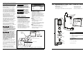
Maintenance
(Continued)
3. Inspect the terminals and clamps
for corrosion and tightness. Clean
and tighten as required.
4. Unplug the main pump and fill sump
with water until back up pump turns
on. Repeat process two times to be
sure pump is operating normally.
5. If pump operates normally, plug
PS/BC into wall outlet, turn on main
pump. If pump fails to operate
normally, see Troubleshooting guide
and correct problem. Repeat step 5.
Pump Installation
Installation of this
unit may take
several hours. Before disabling your
main pump, have ready an appropriate
means of evacuating the sump.
Symptom
Possible Cause(s)
Corrective Action
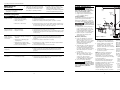
Pump won’t run
1. Connections not secure
2. Low or defective battery
3. Float switch stuck
1. Check all connections
2. Check battery and replace if low or defective
3. Make sure nothing is interfering with operation of switch
Pump Installation
The ESP45 can be installed as a back up
system with a separate dedicated
discharge line (Method 1), or tied into
an existing sump pump line (Method 2).
4. Defective or blown fuse
4. Check internal fuse located on the PS/BC. Pull the charger from
the wall outlet and remove. If the fuse is blown, replace it with
an automotive type fuse of the same amp ratio.
Unplug the existing
AC pump. Failure to
follow this warning could result in fatal
electrical shock.
1. Check battery and replace if low or defective
2. Unplug pump, volute, and check to see if impeller is free to turn.
If impeller is locked, remove the obstruction. Reassemble pump
and reconnect
1. Verify that the existing AC pump is
in good working order. If the AC
pump is questionable, it is typically
recommended that the unit be
replaced with a 1/3 or 1/2 HP pump.
2. Remove any silt or accumulated
debris from the sump pit and
surrounding area.
Pump runs but
pumps very little
or no water
1. Defective battery
2. Impeller is locked
1. Check valve missing or improperly
installed
2. Obstruction in discharge pipe
or pump inlet
3. Discharge pipe length and/or
height exceeds capacity of pump
4. Low or defective battery
1. Check to make sure check valves installed between primary
pump discharge and Backup Sump Pump are functioning
properly
2. Check for obstruction and clear if necessary
3. If discharge is too high, a separate line may be required with a
lower discharge height
4. Check battery and replace if low or defective
Pump cycles too
frequently
1. Check valve problem
No yellow light
1. Battery connection problem
1. Verify battery connection is correct
Red light is on
with alarm
1. Blown pump fuse
2. Low battery voltage
1. Check fuse and replace with a fuse of same rating and size
2. Check battery voltage. PS/BC will not charge batteries with a
combined voltage of 21.6 VDC or less
1. Check to make sure check valves installed between primary
pump discharge and Backup Sump Pump are functioning
properly
Method 1 (Preferred)
1. Locate the ESP45 on a solid, level
surface in the sump pit. Do not
place the pump on a loose or sandy
surface. Small stones or sand may
damage the pump resulting in
potential pump failure.
2. This pump has a 11/2” NPT discharge.
If a 11/4” discharge pipe is desired,
an adapter (not included) will be
necessary. Smaller diameter piping
will reduce pump flow, rate and
performance.
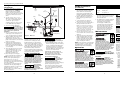
Check Valve
(See Step 6)
PS/BC
Batteries
11/4” or
11/2”
PVC Pipe
Battery
Box
ESP45
Pump
Existing Pump
Figure 2 - Method 1
5. Place the pump with the 4’ section of
PVC pipe on a solid, level surface in
the sump pit on an elevated surface.
6. Attach a rubber check valve (sold
separately) to the top of the
discharge pipe. This will allow the
pump or check valve to be removed
easily for servicing.
7. Check valve is required for effective
operation of system.
3. Cut a 4’ section of 11/4" or 11/2"
diameter rigid PVC pipe. Cement
11/4" pipe to a threaded fitting.
Cement 11/4" pipe into pipe
coupling. Attach 11/4" pipe section
to the ESP45 discharge adapter.
NOTE: Check valves can be placed
directly in the pump discharge if
desired. However, for ease of
disassembly, it is recommended that
check valves be placed above the sump
as shown in Figure 2.
4. Screw on to pump discharge.
The remainder of the discharge pipe
installation will vary depending on
individual circumstances. Using sound
plumbing practices, route the
discharge pipe to an exterior wall by
the shortest path. Keep turns to a
minimum because they reduce flow
output of the pump. The pipe that
exits the building structure should be
Be careful not to
strip or cross thread
plastic fittings or check valves. Flex hose
is not recommended. Rigid PVC or metal
pipe is required for a permanent
installation.
Slope
Pipe
Down
Ridgid
PVC
Pipe
1. Turn power to main pump off.
2. Pump must be installed using 11/4”
or 11/2” rigid PVC piping.
Troubleshooting Chart
Motor hums but
pump won’t run
Floor
Joist
www.waynepumps.com
sloped downward so that water will
not freeze in the pipe.
When installing the separate discharge
pipe, drill through the outside wall with
appropriate drilling equipment. Seal the
hole to prevent water from entering.
Method 2
If a separate, dedicated discharge is
not possible as in Method 1, the ESP45
pump can be tied in to the ACoperated pump’s discharge pipe by
installing a “Y” connector. Two check
valves will be required.
1. Locate the ESP45 on a solid, level
surface in the sump pit. Do not
place the pump on a loose or sandy
surface. Small stones or sand may
damage the pump resulting in
potential pump failure.
2. This pump has a 11/2” NPT discharge.
If a 11/4” discharge pipe is desired,
an adapter (not included) will be
necessary. Smaller diameter piping
will reduce pump flow, rate and
performance.
www.waynepumps.com
6
3