1
1. INTRODUCTION
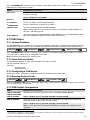
Device Configuration
Device parameters and related system
behavior can be configured from the control
panel or from a remote location.
To configure devices from the control
panel: see Chapter 5 Programming and also
the individual device's Installation
Instructions.
Each PowerG device has its own settings
which can be configured through the control
panel by entering the "DEVICE SETTINGS"
menu.
To configure devices from a remote
location: refer to the PowerManage User's
Guide Chapter 3 Working with Panels and to
the Remote Programmer PC software User's
Guide, Chapters 6 and 7.
Note: The minimum configuration of the
system includes one detector.
Diagnostics of the
control panel and
peripherals
You can test the function of all wireless
sensors deployed throughout the protected
area, to collect information about the
received signal strength from each
transmitter and to review accumulated data
after the test.
To perform diagnostics and to obtain
signal strength indication: see section 5.9
Diagnostics
Conducting periodic
tests
The system should be tested at least once a
week and after an alarm. The periodic test
can be conducted locally or from a remote
location (with the assistance from a nontechnical person in the house).
To conduct a walk test locally: see
Chapter 6 Periodic Test
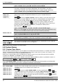
The partitioning feature, when enabled,
divides your alarm system into distinct areas
each of which operates as an individual
alarm system. Partitioning can be used in
installations where shared security systems
are more practical, such as a home office or
warehouse building.
1. Enable partitioning: see section 5.14
Partitioning
Two-way voice
1
communication
The PowerMaster system enables voice
communication with Monitoring Stations
To enable and configure two way voice:
see section 5.6.4 Configuring Events
Reporting to Monitoring Stations
Device configuration
templates
The default parameters with which a new
device is enrolled into the system can be set
before you enroll devices. This default
template saves time on device configuration.
1. Define enrollment defaults for devices:
see section 5.4.6 Defining Configuration
Defaults for "Device Settings"
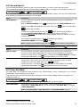
All PowerG smoke detectors are able to
function as sirens, alerting on any of 4 types of
alarm in the system: fire, gas, burglary and
flood.
Enable and configure SirenNet for each
smoke detector: refer to the SMD-426 PG2
/ SMD-427 PG2 Installation Instructions
Partitions
SirenNet - distributed
siren using Smoke
detectors
To conduct a walk test from remote
location: refer to the Remote Programmer
PC software User's Guide, Chapter 6 Data
Details Tables.
2. Setup partition association for each
device: see section 5.4.2 Adding New
Wireless Devices or Wired Sensors
To understand more about partitioning:
see APPENDIX B. Working with Partitions
and APPENDIX A. in the User's Guide.
2. Enroll or pre-enroll devices: see section
5.4.2 Adding New Wireless Devices or Wired
Sensors
Note: For UL installations, smoke detectors
alert only upon fire alarm in the system.
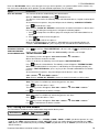
Integrated Siren built
into the panel
The control panel has a high-powered built-in
siren that sounds in case of alarm, enabled by
default.
To define whether or not the control
panel's siren will sound upon alarms: see
section 5.5.5 Configuring Sirens Functionality
Wired Siren outputs
The control panel can operate a wired siren
and strobe devices
Install and connect wired siren: see
section 4.7 Optional Expander Module
Mounting
1
4
Refers to PowerMaster-30 G2 with voice option only
D-304762 PowerMaster-10/30 G2 Installer's Guide