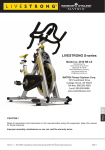
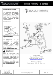
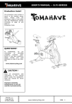
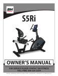
1
GUIDE
OWNER’S
V-Series
Indoor Cycle
Congratulations on choosing a VISION FITNESS Indoor Cycle. You’ve taken an important step in developing and sustaining an
exercise program! Your bike is a tremendously effective tool for achieving your facility’s fitness goals. Regular use of your bike can
improve the quality of your members’ lives in so many ways.
Here are just a few of the health benefits of aerobic exercise:
• Weight Loss
• A Healthier Heart
• Improved Muscle Tone
• Increased Daily Energy Levels
• Reduced Stress
• Help in Countering Anxiety and Depression
• An Improved Self Image
The key to reaping these benefits is to develop the exercise habit. Your new indoor cycle will be an important tool to help your
members achieve this exercise habit. This Owner’s Guide provides you with basic information on using the VISION FITNESS V-Series
indoor cycle.
Some kinds of service to your indoor cycle should be performed by your VISION FITNESS retailer. Please contact your authorized
VISION FITNESS retailer should service be required. If a question or problem arises which cannot be handled by your VISION
FITNESS retailer in North America, please contact us:
VISION FITNESS
1600 Landmark Drive
Cottage Grove, WI 53527
PH: 1.800.335.4348
FAX: 1.608.839.8731
www.visionfitness.com
Product Dimensions:
142cm x 54cm / 56” L X 21.25” W
Product Weight: NW:
49kg / 108 lbs
Max Saddle Height:
108cm / 42.5”
Max Handlebar Height:
130.5cm / 51.4”
Max User Weight:
131.5kg / 290 lbs
Box Dimensions:
112x86x26cm / 44” X 33.8” X 10.2”
Shipping Weight: GW:
54kg / 119 lbs
Designed to accommodate users from 150 cm to 205 cm / 59” to 81” body height.
Page 2
TABLE OF CONTENTS
Important precautions
page 4
Before you begin
page 5
How to assemble the VISION V-series
page 6-8
Initial install checks
page 9
How to adjust the VISION V-series
page 10
Pedal strap adjustment
page 10
Saddle height adjustment
page 10
Saddle horizontal adjustment
page 11
Handlebar adjustment
page 12
Resistance adjustment
page 13
How to move the VISION V-series
page 13
Preventative maintenance
page 14
Daily maintenance
page 14
Weekly maintenance
page 14
Bi-Weekly maintenance
page 15
Monthly maintenance
page 16-17
Belt drive system
page 18
Maintenance activity plan & check lists
page 19
Exploded drawings of structural components
page 20-24
Spare part reference list
page 25
Limited warranty
page 26
Page 3
IMPORTANT PRECAUTIONS
WARNING!
To reduce the risk of serious injury, read the following important precautions and information before
operating the V-Series indoor cycle.
1.
It is the responsibility of the owner to ensure that all users of the Vision V-Series indoor cycle
are informed of all warnings and precautions.
2.
Operate and maintain the Vision V-Series indoor cycle only has described in this manual.
3.
Do not operate the Vision V-Series indoor cycle until it is properly assembled per the instructions
in this manual.
4.
Keep the bike indoors, away from moisture and dust. Do not place the Vision V-Series in a
garage or covered patio or near water.
5.
Place the Vision V-Series indoor cycle on a level surface. To protect the floor or carpet from damage, place a mat beneath the cycle. Make sure that there is adequate room around the Vision
V-Series indoor cycle to mount, dismount, and operate.
6.
Regularly inspect and properly tighten all parts of the Vision V-Series indoor cycle as recommended in this manual. Please replace defective parts immediately and do not use the bike
until repair is performed. Only use original parts from the manufacturer.
7.
Children under the age of 14 should only be allowed use of the Vision V-Series indoor cycle with
parental consent and supervision.
8.
The Vision V-Series indoor cycle should not be used by persons weighing more than 290
pounds (131.5 kg).
9.
Always wear appropriate athletic clothes and shoes while operating the Vision V-Series indoor
cycle. Do not wear loose clothing that could become caught on the cycle or shoes with loose
laces.
10. Before using the Vision V-Series indoor cycle, make sure that you are familiar with the operation
of the cycle.
11. The Vision V-Series indoor cycle does not have an independently moving flywheel; the pedals
will continue to move together with the flywheel until the flywheel stops.
12. Always regulate the flywheel resistance so that your pedaling motion is controlled.
13. Keep your back straight while cycling; do not arch your back.
14. If you feel pain or dizziness while exercising, stop immediately, rest and cool down.
15. If replacement parts are needed, use only manufacturer supplied parts.
WARNING:
Before beginning any exercise program, consult your physician. This is especially important for
persons over the age of 35 or persons with pre-existing health problems. Read all instructions before
using. Be aware that incorrect or extensive training may result in serious health injuries. The manufacturer assumes no responsibility for personal injury or property damage sustained by or through the
use of this product.
Page 4
BEFORE YOU BEGIN
IMPORTANT: Read this manual carefully before assembling or using the indoor cycle.
If you have questions after reading this manual, please contact your local Vision Fitness
dealer or refer to www.visionfitness.com. Before reading further, please familiarize
yourself with the parts that are labeled in the drawing below.
Emergency Brake & Resistance Knob
Saddle
T- Lock
Handle
Adjustment
Knob
Pedal /
Toe Clip
Chain Guard
Maintenance
Cover
Handlebar
Adjustment
Knob
Brake Pad
Flywheel
Transport
Wheel
Levelling
Feet
You will find the production code on the left side of the Vision V-Series within the lower
range of the frame. Please record this number on your service and maintenance list for
easy reference.
Page 5
HOW TO ASSEMBLE VISION V-Series
2x
1x
SW 17mm
SW 14mm
3mm
15mm Pedal
Wrench
hand tight
1
2
Assure that plastic gasket is placed between
rear stabilizer and frame.
Assure that black rubber washer is placed
between upper frame and bolt/washer.
3
4
Assure that plastic gasket is placed between
front stabilizer and frame.
Assure that black rubber washer is placed
between upper frame and bolt/washer.
Please assure that nuts are tightened with significant strength to minimize loosening during use.
Page 6
HOW TO ASSEMBLE VISION V-Series
2x
1x
SW 17mm
SW 14mm
3mm
15mm Pedal
Wrench
5
hand tight
6
STOP mark
7
Make sure the seat is fixed properly in
a LEVEL HORIZONTAL position and
securely tightened!
Page 7
HOW TO ASSEMBLE VISION V-Series
2x
1x
SW 17mm
SW 14mm
3mm
15mm Pedal
Wrench
8
hand tight
9
STOP mark
10
11
Pedal marked R installed on right crank (clockwise). Pedal marked L installed on left crank
(counter-clockwise) Pedals must be fastened with significant strength and a 15 mm pedal
wrench to avoid loosening during use.
Page 8
INITIAL INSTALL CHECKS
The cycle tune-up must be performed at initial installation of the VISION V-Series for optimal performance and
longevity. Please read and follow all instructions below. If the VISION V-Series is not installed and tuned as
described, components may wear excessively and the VISION V-Series may become damaged. If you have
questions about the installation, please contact Vision Fitness.
Note: Some maintenance procedures require WD-40 (refillable spray bottle recommended) or Brunox spray
lubricant, and White Lithium grease.
1.
2.
3.
4.
5.
6.
7.
8.
9.
10.
11.
Make sure that the VISION V-Series is level. If the VISION V-Series rocks on the
floor, turn the leveling feet underneath the front and/or rear stabilizer until the rocking motion is
eliminated.
Verify Emergency brake function to assure that emergency brake functions correctly.
Brake pad calibration: Turn resistance knob counterclockwise as far as possible (minimum bra-
king effect), verify that there is a slight separation of the brake pad from flywheel. Brake pad should barely touch the flywheel when resistance knob is turned counter-clockwise as far as it can go.
Apply WD40 or Brunox spray lubricant to the brake pad. Make sure brake pad is thoroughly
soaked from end to end with lubricant spray. Then, wipe the excess off from the flywheel.
* Best Practice: Use a refillable spray bottle filled with non-aerosol WD-40 purchased by the gallon (3.7 L) at the local hardware store.
Apply Lithium grease to the threads on the lower end of the brake rod. First, turn the resistance knob clockwise until it stops. Apply a small amount of white lithium grease to the threads on the brake rod above the two lock nuts. Then, turn the resistance knob counter-clockwise until it stops.
Apply Lithium grease on the metal threads of all the adjustment knobs.
Check four (4) Allen nuts on RS pulley for tightness. If loose, apply LocTite Threadlocker Blue242 and retighten.
Check R and L crank arm Allen bolts for tightness. If loose, apply LocTite Threadlocker Blue-242 and retighten.
Verify belt tension. Check if belt drive is firmly tightened and does not slip while riding under a resisted load. In case that the belt slips, proceed using the adjustment technique as described on page (18). Please note that a belt drive gear never shows slack. During adjustment do not
apply too much tension.
Wipe down bike frame with cloth moistened with WD-40
Some parts of the VISION V-Series may become loose during shipment. Check crank arms,
check all exposed screws, bolts, and nuts, and make sure that they are properly tightened.
Customer Service
1.
Provide basic maintenance instructions to client and direct them to the detailed maintenance
instructions provided in this manual.
2.
Sign-off sheet provided to client to confirm explanation of maintenance procedures/manual and to verify the condition of bikes.
Page 9
HOW TO ADJUST THE VISION V-Series
The Vision V-Series can be adjusted for maximum comfort and exercise effectiveness.
The instructions below describe one approach to adjusting the cycle to ensure optimal
user comfort and ideal body positioning; you may choose to adjust this cycle differently.
Pedal strap adjustment:
Sit on the saddle and position your feet on the pedals, with the balls of your feet directly
above the spindles of the pedals (see the drawing below). Adjust the pedal straps so the
toe clips (cages) are snug but not too tight.
Please do not adjust
handlebar height beyond
the STOP mark on the stem
and ensure the pop pin is
fully engaged and securely
tightened (see page 8).
Please do not adjust saddle
height beyond the STOP
mark
on
the
stem
and ensure the pop pin is
fully engaged and securely
tightened (see page 8).
Saddle height adjustment:
Sit on the saddle and slowly pedal until the right pedal is in the lowest position. Your knees
should be slightly bent without dropping the hips. To avoid hyper extending the knees,
make sure that your legs are not completely straight.
Page 10
HOW TO ADJUST THE VISION V-Series
Saddle horizontal adjustment:
Proper horizontal adjustment of the saddle is very important in avoiding injury to the knees.
Sit on the saddle and move the pedals until the crank arms are in a horizontal position.
Using your forward most leg as a marker, your knee cap should be directly above
the center of the pedal so that a straight line is created between the knee and center
of the pedal (see the dotted line in image below). To adjust the horizontal position of
the saddle, first dismount the indoor cycle; next, loosen the rear adjustment knob,
slide the saddle forward or backward as required, and then retighten the knob.
Page 11
HOW TO ADJUST THE VISION V-Series
Handlebar adjustment:
Begin with the top of the handlebar at relatively the same height or just slightly higher than
the top of the saddle (dotted horizontal line A in the drawing below) and at a neutral fore/
aft position (see dotted vertical line B in drawing below). If your knees touch the handlebars or if you experience back discomfort while pedaling for extended periods of time, the
height of the handlebars can be adjusted. First, dismount the Vision V-Series indoor cycle;
next, turn the front adjustment knob counter clockwise, slide the handlebar post up or down,
and then retighten the adjustment knob.
B
A
Next the horizontal position of the handlebar should be adjusted. If the handlebar is too close to the saddle, your breathing may feel restricted; if the handlebar is too far from the saddle
you may experience back discomfort. To adjust the horizontal position of the handlebar, first
dismount the Vision V-Series indoor cycle. Check for proper handlebar position by placing
your elbow so it’s touching the front tip of the saddle at a 90 degree angle and checking that
the fingertip of your middle finger is touching the handlebar at the mid-point, and then tighten
the lever handle.
The handlebar offers a variety of hand positions for personal preferences. Changing your
hand position can change the angle of your back, neck and arms. To minimize the stress on
your muscles during your workouts, change your hand position frequently.
Page 12
HOW TO OPERATE THE VISION V-Series
Resistance adjustment:
The preferred level of difficulty in pedaling (resistance) can be regulated in fine increments
by use of the resistance knob. To increase the resistance, turn the resistance knob
clockwise. To decrease the resistance, turn the knob counter clockwise.
IMPORTANT: To stop the flywheel while pedaling, push down the red resistance knob
in the center of the frame. The flywheel should quickly come to a complete stop. Please
make sure your shoes are fixed into the toe clip.
!
The Vision V-Series indoor cycle does not have a free moving flywheel; the
pedals will continue to move together with the flywheel until the flywheel
stops. Reducing speed in a controlled manner is required. To stop the
flywheel immediately, push down the red resistance knob. Always pedal
in a controlled manner and adjust your desired cadence according to your
abilities.
!
Resistance Knob (red)
Emergency brake
How to move the VISION V-series:
Due to the weight of the Vision V-Series indoor cycle, it is recommended that two people
move it. While one person lifts the back of the cycle, the second person firmly holds the
handlebars and tips the cycle down until it rolls on the wheels. Carefully move the indoor
cycle to the desired location and lower it. CAUTION: To reduce the risk of injury, use
extreme caution while moving the indoor cycle. Do not attempt to move it over
uneven surfaces and make sure a safety space of a minimum of 20 inches to the
nearest equipment is achieved.
If the Vision V-Series indoor cycle rocks
on the floor after being set down, turn the
leveling feet (see diagram) underneath the
front or rear stabilizer until the rocking motion
is eliminated. Important: Please do not
unscrew the leveling feet more than ½ inch.
levelling feet
Page 13
PREVENTATIVE MAINTENANCE
Regular maintenance must be performed on the Vision V-Series indoor cycle for
optimal performance and longevity. Please read and follow all the instructions
below. If the indoor cycle is not maintained as described, components may wear
excessively and the indoor cycle may become damaged. Improper maintenance
will void the warranty terms. If you have questions about maintenance, contact
your local Vision Fitness dealer or go to www.visionfitness.com.
Note: Many maintenance procedures require lubricant spray. Manufacturer
recommends WD40, Brunox or any other solvent free lubricant.
Daily maintenance:
1. Make sure the Vision V-Series is level. If the Vision V-Series indoor cycle rocks
on your floor, turn the leveling feet underneath the front or rear stabilizer until the
rocking motion is eliminated.
2. After each user finishes exercising, the cycle should be disinfected and cleaned to
maintain a hygienic environment. First apply a disinfectant spray to the handlebars
and the saddle. Using a lint free cloth, dry the handlebars and the saddle. Next,
apply a small amount of disinfectant to a lint-free cloth and clean the adjustment
knobs and the lock handles. Avoid using strong detergents on the Vision V-Series
indoor cycle frame.
Weekly maintenance:
1. Apply a small amount of the lubrication spray to a lint-free cloth and thoroughly clean
the frame, the handlebar slider, seat slider, the flywheel and the plastic parts of the
Vision V-Series indoor cycle.
2. For optimal performance of the resistance
system and to minimize wear on the brake
pad, WD40 or Brunox lubricant spray should
be applied directly to the brake pad. If fuzz or
lint appears on the brake pad, the brake pad
has become too dry and lubricant spray should
be applied more frequently. Make sure brake
pad is thoroughly soaked from end to end with
lubricant spray, and then wipe off excess.
2
Page 14
PREVENTATIVE MAINTENANCE
Bi-weekly maintenance:
1. The Vision V-Series indoor cycle should not
be used if the emergency brake system is not
working properly. While sitting on the saddle
and pedaling, test the brake by pushing the
brake downward. The flywheel should come
to a quick and complete stop.
2. To maintain easy adjustability of the saddle
post, the post should be cleaned and
lubricated. Turn the rear adjustment knob
counter clockwise and slide the saddle post
out of the frame. Apply a small amount of
lubricant spray to a lint-free cloth, and clean
the saddle post (A). Next, apply a small
amount of WD40 or Brunox lubricant spray
inside the rear frame sleeve. Then reinsert
the saddle post into the frame and adjust it
to the desired height. Next, loosen the rear
lock handle and slide the saddle carriage as
far backward as possible (B). Apply a small
amount of WD40 or Brunox lubricant spray
to a lint free cloth, and clean the top of the
saddle slide. Finally adjust the saddle to the
desired position.
1
2
B
A
Page 15
PREVENTATIVE MAINTENANCE
3. To maintain easy adjustability of the handlebar
post, the handlebar post should be cleaned
and lubricated. First, turn the front adjustment
knob counter clockwise and slide the handlebar
post out of the frame. Apply a small amount of
lubricant spray to a lint-free cloth and clean the
handlebar post (A). Next, apply a small amount
of WD40 or Brunox lubricant spray inside of the
front frame sleeve.
3
A
Then reinsert the handlebar post into the frame
and adjust it to the desired height. Next, loosen
the front lock handle and slide the handlebar
carriage as far backward as possible. Apply
a small amount of lubricant spray to a lint-free
cloth, and clean the surface of the handlebar
slide. Then slide the handlebar carriage as far
forward as possible and clean the top of the
handlebar slide. Finally, adjust the handlebar to
the desired position.
Monthly maintenance:
1. To maintain the smooth function of the
adjustment knobs controlling the handlebar
and saddle, the metal threads on the
adjustment knobs (B) must be lubricated. Use
of white lithium grease is recommended.
1
B
Page 16
PREVENTATIVE MAINTENANCE
2. To maintain the easy adjustability of the
resistance system, the threads on the lower
end of the brake rod should be lubricated.
First, turn the resistance knob clockwise until it
stops. Next, look under the right or left side of
the frame and locate the brake rod, which has
two lock nuts on its lower end. Apply a small
amount of synthetic grease (white lithium
grease) to the threads on the brake rod above
the two lock nuts. Then, turn the resistance
knob counter-clockwise until it stops.
2
3
3. Some parts of the Vision V-Series indoor cycle
may become loose as result of repeated use.
Check pedals and toe straps to make sure
they are properly tightened. Next, check all
exposed screws, bolts, and nuts and make
sure that they are properly tightened. Finally
check the saddle to make sure that it is not
loose or damaged. Please use locktite on
loose crank arms and pulley screws.
4. The brake pad will become worn as a result
of repeated use. The Vision V-Series indoor
cycle should not be used if the emergency
brake system is not working properly. Should
you feel that the resistance system’s functions
are deficient, it is essential to fine-tune the
resistance system before the bike is used
again. Please check the setting of the brake
system as follows: first turn the resistance
knob on the brake system as far as it will go to
the left (minimum braking effect). If the setting
is correct, the brake pads should be flush
with the flywheel and barely touching so that
it’s possible to cycle with a hardly noticeable
amount of resistance. The brake pad can
be adjusted using a 10 mm wrench. Next,
check the brake pad for signs of wear. If the
brake pad does show signs of excessive wear,
thoroughly soak the brake pad with lubricant
spray and then wipe off the excess.
4
Page 17
PREVENTATIVE MAINTENANCE
5. Belt drive
Important: A loose belt as well as an over tightened
belt may cause injury of the rider or damage to the
system. Checking belt tension: To check for
a loose belt, sit on the saddle, place your feet on
the pedals, move the pedals until the crank arms
are horizontal. Next, push down the emergency
brake handle and hold it. Then, stand on the pedals
and rock forward and backward. There should be
no play or slip in the drive train. If there is slip or
play in the drive train, this indicates that the belt is
too loose. Correct a slipping belt drive train: To
adjust the belt, pull of the right and left maintenance
covers (A). Loosen the axle nut (B) on both sides of
the flywheel axel by two full turns. Loosen the inner
adjustment nut (D) facing the flywheel axle on each
side. Next, loosen the lock nut (C).
Then, turn both (right and left sides) of the inner
adjustment nuts (D) on the inside of the flywheel
bracket ¼ of a turn at a time (upward on the right;
downward on the left) until the belt is properly
adjusted. Make sure to turn both adjustment nuts
exactly the same amount to avoid misalignment of
the flywheel. Re-check if the amount of play or slip
in the drive train has disappeared.
4
B
A
CD
Finally retighten the two outer lock nuts (C) to secure
the new adjustment and retighten the two axle nuts
(B). At last reattach the maintenance covers (A).
Check if belt drive is firmly tighten and does not slip
while riding under a resisted load. In case the belt
slips, proceed using the same technique described
above. Please note that a belt drive gear never
shows slack. In case of adjustment do not apply to
much tension.
C D
The manufacturer recommends using an ultrasonic
voltage meter adhering to a natural frequency of the
belt of 3200 Hz ± 150 Hz. Ball bearing damage due
to incorrect belt tension is excluded from warranty.
Graphics are the right side
of the Bike (riding position)
Page 18
MAINTENANCE ACTIVITY AND REQUIRED SCHEDULE
Activity
Feet levelling, disinfection and cleaning of the bike
Servicing brake pads, detailed cleaning of the entire bike
Rotation
Details found on
daily
page 14
weekly
page 14
Check emergency brake function
bi-weekly
page 15
Clean and lubricate saddle and handlebar sliders / posts
bi-weekly
page 15-16
Check adjustment knobs
monthly
page 16
Check brake pad for signs of wear and lubricate brake system
monthly
page 17
Check pedals, toe clip and straps for signs of wear
monthly
page 17
Check all connections and fittings to ensure they are secure and properly tightened
monthly
page 17
Check belt drive train
monthly
page 18
Examples of maintenance Plan charts for in house service technicians:
Weekly Maintenance Checklist
Bike No.
Production Code
Observations
Bike No.
Production Code
Observations
Bike No.
Production Code
Observations
Action Taken
Result
Name / Date
Result
Name / Date
Result
Name / Date
Bi Weekly Maintenance Checklist
Action Taken
Monthly Maintenance Checklist
Action Taken
Page 19
SPARE PARTS
Drive Gear Parts
02 40 C MD20 08
02 40 BPG
02 40 90 (4 pcs. set)
02 40 CRMO L E 08
02 40 CRMO R E 08
02 40 C 2RS (4pcs.)
02 40 C S 08
02 40 BE
02 50 A
Brake Parts
02 50 03 A V (set)
02 99 02 PG
02 50 05
(set)
02 50 06
02 50 04
Page 20
SPARE PARTS
Flywheel
02 40 02
(2 pcs. set)
02 40 H L
(4pcs. set)
02 40 BPK
02 40 H (set)
02 40 08 V (set)
incl. 02 40 H
02 40 H L
(4pcs. set)
Handlebar
02 30 01 V (set)
02 99 02 V
bottle holder for handle bar
mounting, incl. mounting
material
02 10 H
02 10 J
Page 21
SPARE PARTS
Chain Guard
02 42 01 E 08
02 42 02 V
02 42 03 V
02 42 04
02 42 04
02 99 03: bolts M4 x 15 for chain guard mounting
Frame
02 10 A V
(2pcs. set)
02 10 A V
(2pcs. set)
02 99 50 V
sticker set complete
Page 22
SPARE PARTS
Saddle Support
0121 VL-3125 SW
02 21 AK
02 21 01 MYR
02 21 01 MYR PK
(2 pcs.)
02 10 K
02 20 02
02 20 01 V
02 10 J
POP PIN for horizontal saddle stem
Pedals
01 40 A (pair)
01 40 A 3 (pair)
Page 23
SPARE PARTS
Rear Stabilizer
02 11 02 V
02 11 V (4 pcs. set)
02 11 06 V
02 11 05 B MYR
Front Stabilizer
02 11 01 V
02 11 A MYR (2 pcs.)
02 11 06 V
02 11 05 B MYR
02 11 V (4pcs. set)
02 11 B MYR (4 pcs. set)
Page 24
SPARE PARTS LIST
Chain Guard
Drive Gear Parts
02 40 CRMO R E 08
Right crank
02 42 02 V
Outer chain guard
02 40 CRMO L E 08
Left crank
02 42 04
Plastic cover
02 40 C S 08
Allen bolt M8x20 (2 pcs.)
02 42 01 E 08
Inner chain guard
02 40 C MD20 08
BB assembly MD20
02 42 03 V
Left cover
02 40 C 2 RS
Ball bearing SKF 6004Z (4pcs)
02 99 03
Allen bolt M4x15
02 40 BE
Belt
02 40 BPG
Pulley rear
Pedals
01 40 A
Combi-Pedals (pair)
01 40 A 3
Toe strap (pair)
Brake Parts
02 50 A
Brake adjustment knob
02 50 06
Bell crank
02 50 04
Brake pad
02 50 03 A V
Upper brake rod (set)
02 50 05
Lower brake rod (set)
02 99 02 PG
plastic guard
Flywheel
02 40 H
Flywheel axle (set)
02 40 02
Chain tensioner
02 40 H L
Flywheel bearing 6001Z (4pcs)
02 40 08 V
Vision-series flywheel
02 40 BPK
Pulles front incl. lock ring
Frame
02 10 A V
Vertical insert sleeve (2 pcs)
02 99 50 V
sticker set complete
Handlebar
02 30 01 V
V-series handlebar (set)
02 10 J
Pop pin adj. knob
02 11 H
Lever handle horztl. adjustm.
02 99 02 V
Bottle holder handle bar
Saddle Support
0121 VL-3125 SW
Saddle
02 21 AK
Saddle mounting bracket
02 21 01 MYR
Horizontal saddle support
02 20 01 V
Vertical saddle support
02 10 K
T- Lock handle
02 10 J
Pop pin adj. knob
02 21 01 MYR PK
Endcaps (2 pcs)
02 20 02
Insert sleeve horztl. saddle sup.
Rear Stabilizer
Front Stabilizer
02 11 01 V
Front Stabilizer
02 11 B MYR
Stabilizer mounting kit
02 11 06
Plastic end cover
02 11 05 B
Rubber foot stand
02 11 V
Gasket/plate set (4 pcs)
02 11 A MYR
Transport wheel
02 11 02 V
Rear stabilizer
02 11 B MYR
Stabilizer mounting kit
02 11 06
Plastic end cover
02 11 05 B
Rubber foot stand
02 11 V
Gasket/plate set (4 pcs)
Page 25
WARRANTY TERMS
Vision Fitness warrants that all new equipment will be free from manufacturing defects in
workmanship and materials, becoming effective on the date of purchase. Parts repaired
or replaced under the terms of the warranty will be warranted for the remainder of the
original warranty period only. Warranty may vary by region or country.
Defects caused by inappropriate use or handling of the product may cause denegation
of the manufacturer warranty.
LIMITED HOME-USE WARRANTY
Vision Fitness extends the following exclusive, limited warranty, which shall apply only to
the use of the device in the home, for residential, non-commercial purposes. Any other
use of this device shall void this warranty.
WEIGHT CAPACITY = 290 lbs (131.5 kgs)
5 Year warranty: Frame construction, breakage, welding defects
2 Year warranty: Handlebar and saddle assembly, brake system (excluding
brake pad), lever handles and adjustment knobs, cranks, belt
drive system, bottom bracket assembly, ball bearings, flywheel
and hub assembly, powder coating, plastic components such
as chain guard and left side hub cover, sweat guard, platform
pedals (shoe cage system excluded), insert sleeves for
handlebar and saddle post, and leveling feet;
Labor 1 Year:
Vision Fitness shall cover the labor cost for the repair of the
device for a period of 1 year from the date of original purchase,
so long as the device remains in possession of the original
owner.
6 Month warranty: Pedal straps, brake pads, pedal binding system, bottle holder,
and saddle
Product failures due to mechanical influence, negligent handling or improper use may void
warranty.
Frequent service and maintenance according to the procedures described in this manual
are prerequisites to uphold warranty.
Page 26
EXCLUSIVE REMEDY
The exclusive remedy for any of the above warranties shall be repair or replacement of
defective parts, or the supply of labor to cure any defect, provided the labor shall be limited
to one year. All labor shall be supplied by the local Retailer and the product must be located
within that Retailer’s service area. Products located outside the Retailer’s service area will
not be covered by the labor warranty.
EXCLUSIONS AND LIMITATIONS
This warranty applies only to the original owner and is not transferrable. This warranty is
expressly limited to the repair or replacement of a defective part and is the sole remedy of
this warranty.
What is NOT covered?
• Normal wear and tear, improper assembly or maintenance, or installation of parts or
accessories not originally intended or compatible with the equipment as sold.
• Damage or failure due to accident, abuse, corrosion, discoloration of paint or plastic,
neglect, theft, vandalism, fire, flood, wind, lightening, freezing, or other natural
disasters of any kind, power reduction, fluctuation or failure of whatever cause,
unusual atmospheric conditions, collision, introduction of foreign objects into the unit
or modifications that are unauthorized or not recommended by Vision Fitness.
• Incidental or consequential damages, Vision Fitness is not responsible or liable for
indirect, special or consequential damages, economic loss, loss of property or profits,
loss of enjoyment or use, or other consequential damages of whatsoever nature in
connection with the purchase, use, repair or maintenance of the equipment.
• Equipment used for commercial purposes or any use other than a single family or
household, unless endorsed by Vision Fitness for coverage.
• Equipment owned or operated outside the US and Canada.
• Delivery, assembly, installation, setup for original or replacement units or labor or other
costs associated with removal or replacement of covered unit.
• Any attempt to repair this equipment creates a risk of injury. Vision Fitness is not
responsible or liable for any damage, loss or liability arising from any personal injury
incurred during the course of, or as a result of any repair or attempted repair of your
fitness equipment by any other than an authorized service technician. All repairs
attempted by you on your fitness equipment are undertaken AT YOUR OWN RISK and
Vision Fitness shall have no liability for any injury to the person or property arising from
such repairs.
VISION FITNESS expressly disclaims all other warranties, express or implied, including
but not limited to all warranties of fitness for a particular purpose or of merchantability. This
warranty gives you specific legal rights, and your rights may vary from state to state.
WARRANTY REGISTRATION
Register your product at www.visionfitness.com.
By registering your product within the next 10 days, we can confirm the date of purchase if
you should need to contact customer support for warranty service or if your original proof
of purchase is lost. If you have any questions, contact customer support at 800-335-4348.
Page 27
COMMERCIAL WARRANTY
VISION FITNESS warrants the Vision V-Series indoor cycle for use in commercial
facilities including: hotels, resorts, police and fire stations, apartment complexes,
corporate fitness centers, hospitals, rehabilitation and sports medicine clinics, where
average use is up to six hours per day.
WEIGHT CAPACITY = 290 lbs (131.5 kgs)
5 Year warranty: Frame construction, breakage, welding defects
2 Year warranty: Handlebar and saddle assembly, brake system (excluding
brake pad), lever handles and adjustment knobs, cranks, belt
drive system, bottom bracket assembly, ball bearings, flywheel
and hub assembly, powder coating, plastic components such
as chain guard and left side hub cover, sweat guard, platform
pedals (shoe cage system excluded), insert sleeves for
handlebar and saddle post, and leveling feet;
1 Year warranty:
Saddle
Labor 90 Days: Vision Fitness shall cover the labor cost for the repair of the
device for a period of 90 days from the date of purchase, so
long as the device remains in the possession of the original
owner.
The following wear items are excluded from warranty:
• Pedal straps
• Water bottle holder
©2010 Vision Fitness. All Rights Reserved.
Vision V-Series Indoor Cycle Owner‘s Guide. Rev 1.1
Page 28