1
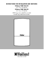
INSTRUCTIONS FOR INSTALLATION AND SERVICING
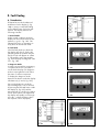
ECOmax VUW 236 EH
G.C. No. 47 044 23
ECOmax VUW 286 EH
G.C. No. 47 044 24
Wall hung room sealed fan assisted
condensing combination boilers
HEATING, CONTROLS, HOT WATER
1. Introduction
Page
3
2. Boiler Specification
2.1 Technical Data
2.2 Dimensions
2.3 Boiler connections
2.4 Function diagram
4
4
5
5
6
3. General Requirements
7
3.1 Related documents
7
3.2 Boiler location
8
3.3 Gas supply
9
3.4 Flue system
9
3.5 Air suply
11
3.6 Electricity supply
11
3.7 Guide to system requirements 11
4. Boiler installation sequence
4.1 General
4.2 Boiler delivery
4.3 Preparation of boiler location
4.4 Pipework connections
4.5 Installing the flue system
4.6 Mounting the boiler
4.7 Connecting the flue assembly
4.8 Electrical installation
4.9 Controls
14
14
14
15
17
18
18
20
22
23
5. Commissioning
5.1 Preliminary electrical checks
5.2 Gas supply
5.3 Water supply
5.4 Filling the heating system
5.5 Initial system flush ('cold')
5.6 Filling condensate trap
5.7 Initial lighting
5.8 Gas inlet working pressure
5.9 Adjusting central heating
output (range rating)
5.10 Main burner pressure
5.11 Functional checks
5.12 Checking flame
supervision device
5.13 Final system flush ('hot')
5.14 Fitting case
5.15 Handing over to user
25
25
25
25
26
26
27
27
28
28
29
30
32
33
33
33
6. Servicing
6.1 Initial inspection
6.2 Routine maintenance
6.3 Recommisioning the boiler
Page
34
35
35
37
7. Parts replacement
7.1 Initial preparation
7.2 Fan
7.3 Air pressure sensor
7.4 Burner
7.5 Electrodes
7.6 Condensate sump
7.7 Condensate trap
7.8 Temperature sensors (NTCs)
7.9 Gas valve
7.10 Main Heat exchanger
7.11 CH expansion vessel
7.12 Main safety isolating
transformer
7.13 Ignition transformer
7.14 Pump
7.15 Automatic air release
7.16 Automatic bypass
7.17 Diverter valve
7.18 Pressure gauge
7.19 Water section
7.20 DHW microswitch
7.21 DHW heat exchanger
7.22 Circuit boards
38
38
40
41
41
42
43
44
44
44
45
46
8. Fault finding
8.1 Introduction
8.2 Logical fault finding procedure
8.3 Fault finding using fault mode
8.4 Fault diagnosis using
status mode
57
57
58
60
47
48
48
49
49
50
51
51
52
53
53
62
9. Electrical diagrams
9.1 Functional flow diagram
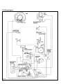
9.2 Wiring diagram
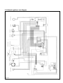
9.3 Schematic appliance
circuit diagram
65
65
66
67
10. Short parts list
68
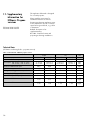
11. Supplementary information
for ECOmax
70
THE GAS SAFETY (INSTALLATION AND
USE) REGULATIONS 1994:
`In your own interest, and that of
safety, it is law that all gas appliances
are installed by competent persons, in
accordance with the above regulations. Failure to install appliances
correctly could lead to prosecution.'
Leave these instructions with the user
when the installation is completed.
2
1. Introduction
Note: This boiler must be installed and
serviced by a competent person in
accordance with the Gas Safety
(Installation and Use) Regulations
1994. In the U.K. `CORGI' Registered
Installers undertake the work to a safe
and satisfactory standard.
ECOmax is a fully automatic, wall
mounted, room sealed, condensing
(high efficiency) combination boiler
for central heating and domestic hot
water. Domestic hot water is supplied
directly from the boiler, and has priority
over the central heating. (This has the
advantage that no copper cylinder,
cold water tank, feed and expansion
tank and associ-ated pipework are
required).
The boiler has been designed for use
with sealed systems, and comes fully
tested and assembled with built-in
circulating pump, bypass, expansion
vessel and diverter valve.
The boiler, because it has a larger
heat exchanger, extracts more heat
from the flue gases. The conversion of
this otherwise wasted heat into usable
warmth means the boiler has a higher
efficiency. Because the flue gases are
reduced to such a low temperature,
the water vapour contained in them
can condense. To discharge this condensate a drain is provided on the
boiler, and this must be connected to
a drainage point on site.
The boiler features a comprehensive
diagnostic system, which gives detailed information on the boiler status
when operating and performance of
key components to aid in commissioning and fault finding.
ECOmax range consists of models
with outputs for domestic hot water
of 22.7 and 28.3 kW. The boiler is
easily sited on any internal wall
and can be installed with either a
horizontal or vertical RSF (Room
Sealed Fan assisted) flue. Flue
extensions and additional bends and
elbows are available for increased
siting flexibility. (The boiler is not
suitable for external installation).
If desired, an inhibitor may be used
in the system. Guidance on the use
of inhibitors is contained in these
instructions. (The boiler does not utilise
aluminium in the water system and
does not require a special inhibitor).
The boiler is designed to operate on
Natural Gas only.
The boiler contains a domestic hot
water heat exchanger. The temperature in the heat exchanger is limited by
the boiler control system and it is not
normally necessary to install a scale
reducer on the cold mains inlet to the
boiler. However, in exceptionally hard
water areas to prevent scale formation
in the property hot water system pipework a scale reducer may be fitted.
The data badge is fitted on the combustion chamber cover.
ECOmax boilers carry the „CE” Mark.
This demonstrates that the boilers fulfill
the essential requirements of the Gas
Appliance Directive (90/396/EEC)
and the Gas Appliance (Safety)
Regulations 1992.
The „CE” Mark also demonstrates
that the boilers comply with the
requirements of the Electromagnetic
Compatibility Drective
(89/336/EEC), the Low Voltage
Directive (73/23/EEC), the Boiler
Efficiency Directive (92/42/EEC)
and the Boiler (Efficiency) Regulations
1993.
3
2. Boiler specification
2.1 Technical data
ECOmax
VUW 236 EH
Countries of Destination
Maximum CH heat input
CH heat output range
80 °C flow/60 °C return
units
GB, IE
19.5 (66,500)
24.2 (82,600)
kW (Btu/h)
9.9-17.2
(33,800-58,700)
12.3-21.3
42,000-72,700)
kW
(Btu/h)
10.5-18.0
(35,800-61,400)
13.1-22.3
(44,700-76,100)
kW
(Btu/h)
Maximum DHW heat input
Maximum DHW heat output
DHW flow rate @ 35 °C rise
Mains water pressure required for max. flow rate
Minimum water flow rate
Mains water pressure required for min flow rate
Maximum inlet water pressure
25.0 (85,300)
22.7 (77,500)
9.3
1.0
2
0.2
10
31.1 (106,100)
28.3 (96,600)
11.6
1.0
2
0.2
10
kW (Btu/h)
kW (Btu/h)
l/min
bar
l/min
bar
bar
Inlet gas working pressure required (Natural Gas)
Gas supply (G20) Gross C.V. (s.t.)
Gas burner pressure max (DHW)
Gas rate max (DHW)
20
37.8
3.0
2.38
20
37.8
3.0
2.96
mbar
MJ/m3
mbar
m3/h
CH flow temperature range
Minimum CH water flow (for 20 °C rise)
Pump pressure available
12 l expansion vessel pre-charge pressure
Maximum CH system pressure
35-90
770
0.25
0.8
3.0
35-90
960
0.25
0.8
3.0
°C
l/h
bar
bar
bar
3/4
3 /4
15
15
15
19
15
15
15
15
19
15
in. BSP
mm
mm
mm
mm
mm
56
1.5
0.5
70
57
1.6
0.6
70
kg
litres
l/h
°C
230/50
2/3
130
230/50
2/3
130
V~/Hz
A
W
50 °C flow/30 °C return
Connections
Heating flow / return
Cold water inlet
DHW outlet
Gas inlet
Condensate drain (internal diameter, min)
Pressure relief discharge pipework (min)
Weight
Boiler water content
Volume of condensate (max.)
Maximum flue gas temperature
Electrical supply
Voltage
Fuses internal/external
Power input
4
VUW 286 EH
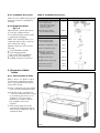
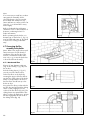
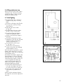
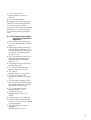
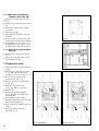
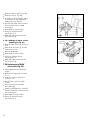
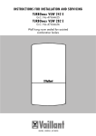
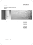
2.2 Dimensions
(All dimensions in mm)
1a
1b
2
3
4
5
6
11
12
13
14
Air/flue duct to the rear
Air/flue duct to the side
Appliance bracket
Heating system return 3/4” Rp
(3/4” B.S.P.)
Cold water connection (15 mm)
Gas connection (15 mm)
Hot water connection (15 mm)
Heating system flow 3/4” Rp
(3/4” B.S.P.)
Pre-assembled connection set
with service valves (flow and
return) pressure relief valve,
cold and hot water connection
Pressure relief valve 3/4” Rp
(3/4” B-S.P.)
Boiler condensate drain
(18 mm O. D.)
fig. 1
GW 398/0
fig. 2
GW 399/1
* with standard horizontal flue
accessory.
(max. = 6880 mm with extensions)
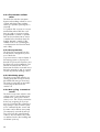
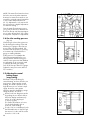
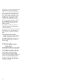
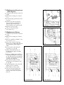
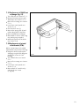
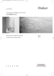
2.3 Boiler connections
1 Connection support bracket
2 Service valve (flow of heating
system)
3 Domestic hot water connection
4 Compression Union (gas)
5 Gas service valve (supplied with
the boiler)
6 Cold water connection with
shut-off walve
7 Service valve (return of heating
system)
8 Discharge pipe
9 Pressure relief valve
10 Compression union (return of
heating system)
11 Compression union (flow of
heating system)
14 Boiler condensate drain
23 Frame of appliance (lower
connection)
5
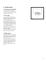
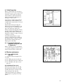
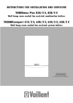
2.4 Function diagram
fig. 3
6
GW 512/1
1 Air duct
2 Flue gas duct
3 Fully modulating automatic gas
valve
4 Fully modulating fan
5 Fully modulating low NOx burner
6 Combustion chamber
7 Flame sensing electrode
8 High efficiency heat exchanger
9 Condensate trap
10 DHW heat exchanger
11 Boiler display
12 User control panel
13 DHW outlet
14 CH flow service valve
15 Gas service valve
16 Air pressure sensor
17 Ignition electrodes
18 Temperature sensors (NTCs)
19 Expansion vessel charging valve
20 Expansion vessel
21 Automatic bypass valve
22 Automatic air vent
23 Circulating pump
24 Diverter valve
25 Pressure gauge
26 Water section
27 Pressure relief valve
28 CH return service valve
29 Cold water shut off valve
3. General requirements
3.1 Related documents
The installation of the boiler must be in
accordance with the relevant requirements of Gas Safety (Installation and
Use) Regulations 1994, Health and
Safety Document No. 635 (The Electricity at Work Regulations 1989),
BS7671 (IEE Wiring Regulations) and
the bylaws of the local Water Undertaking. It should be in accordance
with any relevant requirements of the
Local Authority, Building Regulations,
Building Standards (Scotland) Regulations and the relevant recommendations of the following British
Standards:BS 5440: Flues and ventilation of gas
fired boilers not exceeding 60 kW:
- Part 1: Flues
- Part 2: Ventilation
BS 5449: Specification for forced
circulation hot water for domestic
premises.
BS 5546: Specification for gas hot
water supplies for domestic premises.
BS 6700: Services supplying water
for domestic use within buildings and
their curtilages.
BS 6798: Specification for installation
of gas fired boilers not exceeding
60 kW input.
BS 6891: Specification for installation
of low pressure gas pipework up to
28 mm (R1) in domestic premises
(2nd family gas).
BS 7593: Treatment of water in domestic hot water central heating systems.
BRITISH GAS PUBLICATION DM2:
Guide for Installation in Timber
Framed Housing
Important
The appliance must be installed and
serviced by a competent person as
stated in the Gas Safety (Installation
and Use) Regulations 1994
7
3.2 Boiler location
The location chosen for the boiler must
permit the provision of a satisfactory
flue termination. The location must
also provide adequate space for servicing and air circulation around the
boiler. The boiler may be installed in
any room, although particular attention is drawn to the requirements of
the I.E.E. Regulations and, in Scotland, the electrical provisions of the
Building Regulations, in respect of the
installation of the boiler in a room
containing a bath or shower.
(Note: Where a room sealed boiler is
installed in a room containing a bath
or shower, any electrical switch or
boiler control utilising mains electricity
should be so situated that it cannot be
touched by a person using the bath or
shower).
Where the installation of the boiler
will be in an unusual location, special
procedures may be necessary and BS
5546 and BS 6798 give detailed guidance on this aspect.
The boiler must be mounted on a flat,
vertical wall, which must be sufficiently robust to take the weight of the boiler. The boiler may be installed on a
combustible wall, subject to the
requirements of the Local Authorities
and Building Regulations.
A compartment used to enclose the
boiler must be designed and constructed specifically for this purpose.
(An existing cupboard or compartment
may be used provided that it is modified for the purpose). Details of essential features of cupboard/compartment design including airing cupboard installations are given in
BS 6798.
If the boiler is to be fitted in a timber
framed building, it should be fitted in
accordance with British Gas Publication DM2 `Guide for Gas Installations
in Timber Framed Housing'.
8
3.3 Gas supply
The gas supplier should ensure the
availability of an adequate supply of
gas.
A gas meter may only be connected
to the service pipe by the supplier of
gas or their contractor.
An existing meter should be checked
to ensure that it is capable of passing
the rate of gas supply required.
Installation pipes should be fitted in
accordance with BS 6891.
Pipework from the meter to the boiler
must be of an adequate size. Do not
use pipes of a smaller size than the
boiler gas connection (15mm).
The complete installation must be
tested for soundness and purged as
described in BS 6891.
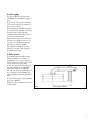
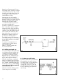
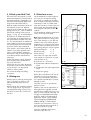
3.4 Flue system
The standard horizontal flue system
(Accy No 300931) is suitable for
installations up to 1 metre measured
from the centre of the boiler flue outlet
to the outside face of the wall
(A, fig. 4). One metre flue extensions
(Accy No 300923) are available to
extend this length up to 6880 mm.
90 ° elbows (Accy No 300934) and
45 ° bends (Accy No 300949) are
also available to increase siting flexibility.
Refer to the flue installation instructions
for full details.
fig. 4
GW 319/0
A vertical flue system is also available
(Accy No 300945).
9
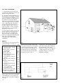
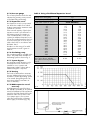
3.4.1 Flue Termination
1. The terminal must be positioned
such that the combustion products can
disperse freely at all times.
2. Flue gases from high efficiency condensing boilers are emitted at relatively low temperatures, leading to a tendency for a plume of water vapour to
be visible at or near the terminal.
More care should therefore be taken
when choosing the site for a terminal
of a condensing boiler. If possible
avoid placing the terminal below a
window, next to a door or close to
opposing walls. It is also recommended that the flue is not terminated
beneath a car port roof.
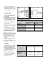
A- Directly below an openable
window or other opening
(e.g. air brick)
300
B- Below gutters, soil pipes
or drain pipes
751
C- Below eaves
2001
D- Below balconies
2001
E- From vertical drain pipes
and soil pipes
25
F- From internal or external
corners
3002
G- Above ground or balcony
level
300
H- From a surface facing a
terminal
600
I- From a terminal facing a
terminal
1200
K- Vertically from a terminal
on the same wall
1500
L- Horizontally from a
terminal on the same wall
300
M-Distance from adjacent
wall for Vertical Flue
500
Note: Vertical flues must not terminate
within 600 mm of an openable window, air vent or any other ventilation
opening.
10
fig. 5
Dimensions B, C and D: These clearances may be reduced to 25mm without affecting the performance of the
boiler. In order to ensure that the condensate plume does not affect adjacent surfaces the terminal should be
extended as shown in fig. 6.
1
fig. 6
Dimension F: This clearance may be
reduced to 25mm without affecting
the performance of the boiler.
However, in order to ensure that the
condensate plume does not affect
adjacent surfaces a clearance of
300 mm is preferred.
2
GW 445/0
Table 1:
Terminal position for fan-assisted flue.
(minimum distance - see fig. 5)
mm
GW 524/0
3. If the terminal is fitted less than 2m
above a balcony, above ground or
above a flat roof to which people
have access then a suitable guard
must be provided and fitted (available
from Tower Flue Components,
Tonbridge, TN9 1TB: reference
CGDK3BL).
3.5 Air supply
Detailed recommendations for air supply are given in BS 5440: Part 2.
It is not necessary to have an air vent
in the room or internal space in which
the boiler is installed.
3.5.1 Cupboard or compartment air supply
ECOmax Room Sealed Condensing
Combination Boilers are very high
efficiency appliances. As a consequence the heat loss from the
appliance casing during operation
is very low. For cupboard and
compartment installations it is therefore not necessary to provide any high
or low level permanent air vents for
cooling purposes.
3.6 Electricity supply
A 230 volts~ 50Hz single phase electricity supply fused to 3 amps must be
provided in accordance with the latest
edition of the I.E.E. Wiring Regulations and any other local regulations
that may apply.
THIS APPLIANCE MUST BE EARTHED.
The method of connection to the mains
electricity supply must provide a
means of completely isolating the boiler and its ancillary controls. Isolation
is preferably by the use of a fused
three-pin plug and unswitched shuttered socket outlet, both complying
with the requirements of BS 1363.
Alternatively, a 3 Amp fused doublepole switch with a 3mm contact separation on both poles may be used.
3.7 Guide to system
requirements
3.7.1 Water circulation system
Detailed recommendations for the
water circulation system are given in
BS 6798 and BS 5449: Part 1 (for
small bore and micro bore central
heating systems).
11
Pipework not forming part of the useful heating surface should be insulated
to help prevent heat loss and possible
freezing, particularly where pipes are
run through roof spaces and ventilated underfloor spaces.
Draining taps must be located in
accessible positions which permit the
draining of the whole system including
the boiler and the hot water system.
Draining taps should be at least
1/2 in. BSP nominal size and be in
accordance with BS 2879.
The boiler is suitable for use with minibore or microbore systems. Copper
tubing to BS 2871: Part 1 should be
used for water carrying pipework. All
capillary joints in the DHW pipework
must be made with lead free solder.
Particularly where a new boiler is to
be fitted to an existing system, it is
good practice that the system is
thoroughly cleansed. This cleansing
should take place prior to the fitting of
the new boiler and be in accordance
with BS 7593.
Heating
circuit
return
For advice on the application of
system cleansers contact sentinel,
Grace Dearbom Ltd.
Widnes., Cheshire, WA8 8 UD.
Tel.: 0151 495 1861
Double check
valve assembly
Hose
unions
Stop
valve
Temporary
Hose
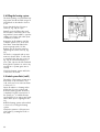
3.7.3 Pressure relief valve
A pressure relief valve is provided ready-assembled to the return C.H. service valve (4, fig. 8). This safety device is required on all sealed C.H.
systems and is pre-set at 3 bar and
provided with a 3/4 in. BSP connection for a discharge pipe (minimum
size 15mm).
fig. 8
12
GW 401/0
(Alternative methods of filling sealed
systems are given in BS 5449).
fig. 7
GW 400/0
Test
valve
3.7.2 Filling and make up
The system should be filled with water
via a separate filling point fitted at a
convenient point on the heating circuit. Where local Water Authority
Regulation allows, a temporary connection to the mains may be used
(fig. 7). The connection must be
removed when filling is completed.
Where local Water Authority Regulation does not allow temporary connection, a sealed system filler pump with
break tank must be used. The heating
system will not be filled automatically
from the domestic side.
Mains
water
supply
3.7.4 Pressure gauge
This is factory fitted to the boiler and
indicates the primary circuit pressure
to facilitate filling and testing.
3.7.5 Expansion vessel
An expansion vessel is incorporated
into the boiler suitable for a sealed
heating system with a maximum water
contents of 135 litres.
If the nominal capacity of the built-in
expansion vessel is not sufficient for
the heating system (for instance in
case of modernization of old open
systems) an additional expansion vessel can be installed external to the boiler in the return pipe as close as possible to the boiler in accordance with
BS 5449: Part 1.
Guidance on the sizing of an additional expansion vessel is given in
Table 2.
3.7.6 Circulating pump
The circulating pump is included in the
boiler. The pump head available for
the heating system is shown in fig. 9.
3.7.7 System by-pass
An automatic system by-pass is included within the boiler. The boiler is
suitable for use in systems with
thermostatic radiator valves and no
additional by-pass is required.
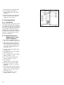
Table 2: Sizing of Additional Expansion Vessel
Safety valve setting (bar)
Initial system pressure (bar)
Total water content of system
litres
25
50
100
125
150
175
200
225
250
275
300
325
350
375
400
425
450
475
500
For system volumes other than
those given above, multiply
the system volume by the factor
across
3.0
1.0
1.5
VESSEL VOLUME (L)
2.7
5.4
10.9
13.6
16.3
19.1
21.8
24.5
27.2
30.0
32.7
35.7
38.1
40.9
43.6
46.3
49.0
51.8
54.5
3.9
7.8
15.6
19.5
23.4
27.3
31.2
35.1
39.0
42.9
46.8
50.7
54.6
58.5
62.4
66.3
70.2
74.1
78.0
0.109
0.156
fig. 9
fig. 10
GW 494/0
3.7.9 DHW expansion vessel
accessory
A DHW expansion vessel kit (Accy.
No. 8070) is available as an optional
extra from Vaillant Ltd. This expansion
vessel kit should be fitted to the boiler
whenever either a stop valve of the
loose jumper type or a non return
valve are present in the cold water
mains supply to the boiler (fig. 10).
GW 402/0
3.7.8 Venting
The boiler is fitted with an automatic
air vent. Additional provision should
be made to enable the heating system
to be vented during filling and commissioning either by automatic air
vents or manually.
13
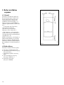
4. Boiler installation
sequence
4.1 General
The boiler should be mounted on a
flat and vertical area of wall of sufficient area for the boiler plus the
required minimum clearances for
installation and servicing (fig. 11).
These are shown on the installation
template supplied with the boiler and
are:5 mm either side of the boiler
150 mm below the boiler
165 mm on top of the boiler
500 mm in front of the boiler *
NOTE: If the boiler is to be fitted in a
timber framed building, it should be
fitted in accordance with British Gas
publication reference DM2 'Guide for
gas installations in timber framed housing.'
4.2 Boiler delivery
ECOmax is delivered in three packs:
a. the carton containing the boiler
b. separately boxed connection group
(Accy No.9313)
c. separately boxed flue accessory,
either:
• 1m horizontal flue accessory
(Accy No. 300931); or
• vertical flue accessory
(Accy No. 300945)
14
fig. 11
GW 403/0
* This clearance is only required to
enable easier access to the boiler for
servicing and may be provided by an
openable door, etc.
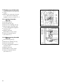
4.2.1 Installation accessories
Table 3 lists the standard and optional
accessories which are available for
ECOmax.
4.2.2 Unpack the boiler
(fig. 12)
Open the boiler carton and remove:
a. protective cardboard sheet
b. top and bottom decorative panels
c. polystyrene packaging
NOTE: Care should be taken not to
scratch the white powder coated surface of the boiler casing.
Packed in the boiler carton are the
following:
• boiler installation template
• boiler hanging bracket
• gas service valve and adaptor
• fixing screws and wallplugs
• installation and user instructions
Table 3: Installation Accessories
Standard Accessories
1) Pre-assembled connection group
incl. isolating valves
(flow and return), pressure
relief valve, cold and hot
water connections
2) Air/flue duct assembly
incl. terminal (horizontal)
Optional Accessories
3) Air/flue duct assembly
incl. terminal (vertical)
Accy. No.
9313
300931
Accy. No.
300945
4) Pitched roof adjustable roof tile
9076
5) Flat roof penetration collar
9056
6) Extension: (1 m) for the
standard air/flue duct
assembly (optional extra)
300923
7) Additional 90 ° elbow
300934
8) Additional 45 ° bends (pair)
300949
9) Internal flue fixing kit
8098
10) Pipe cover accessory
8099
4.3 Preparation of boiler
location
4.3.1 Select position of boiler.
Refer to Section 3.2 `Boiler Location'
for information regarding siting the
boiler. In general the boiler must be
positioned such that:
• there is adequate space around the
boiler for service and maintenance
• the boiler can be correctly flued,
i.e. the flue terminal position is sited
in accordance with Section 3.4.1
and the air / flue duct can be
installed in accordance with the
flue installation instructions
supplied.
• all necessary pipework can be
fig. 12
GW 405/0
connected, including the pressure
relief valve discharge pipe and the
condensate drain.
15
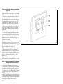
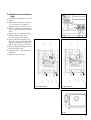
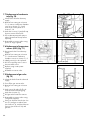
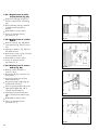
4.3.2 Using the boiler template
(fig. 13)
4.3.2.2 Mark on the wall the positions of the hanging bracket (2) and
connection group fixing holes (3). Drill
two holes Ø 10 mm for the hanging
bracket, and similarly drill three holes
Ø 8 mm for the connection group.
(Note: Use the alternative fixing holes
where necessary).
4.3.2.3 Rear exit flue.
Mark the position of the centre of the
flue duct and its circumference, e.g.
by drilling through the template (1).
4.3.2.4 Other flue options.
Refer to the installation instructions
supplied with the flue accessory for
detailed instructions on other flue options such as vertical RSF flues, flue
runs to the side of the boiler and the
use of additional flue elbows and
bends etc.
4.3.2.5 Remove the template from the
wall and plug the drilled holes using
the wallplugs supplied.
4.3.3 Fitting the boiler hanging
bracket and connection
group.
Secure the hanging bracket and
connection group securely to the wall
using the screws supplied. (If the condition of the wall is poor it may be
necessary to use additional or alternative fixings to ensure adequate support).
NOTE: If the boiler is to be fitted in a
timber framed building ensure that the
brackets are secured to a substantial
part of the timber frame capable of
taking the weight of the boiler.
16
fig. 13
GW 426/0
4.3.2.1 Once a suitable location has
been chosen, fix the paper installation
template on the wall ensuring that the
centerline of the template is vertical
using a spirit level or plumb line.
The template shows the positions of
the fixing holes for the boiler hanging
bracket and connection group. The
template also shows the position of
the flue exit hole, for use where the
air flue duct is to be installed directly
to the rear of the boiler, e.g. where
the boiler is installed on an outside
wall and the flue terminates directly
behind.
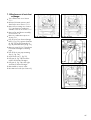
4.4 Pipework connections
(fig. 14)
4.4.1 Central heating flow
and return
Before connecting the heating circuit
to the connection group, all pipework
and radiators must be thoroughly
flushed to remove any installation
debris. Connect the flow and return
pipes to the central heating service
valves (8) and (9) on the connection
group using compression adaptors.
4.4.2 Cold mains water inlet
and hot water outlet
Flush out all foreign matter from the
mains supply pipe before connecting
to the boiler.
Connect the mains water supply (3)
and hot water outlet pipes (4) to the
15 mm compression connections provided.
Note: The boiler has a maximum
domestic water working pressure of
10 Bar. If the cold mains supply pressure exceeds 10 Bar, a pressure reducing valve must be fitted to the cold
water inlet.
fig. 14
GW 406/0
Figure 14 shows the central heating,
domestic hot water, mains cold water
and pressure relief valve connections.
Key:
1
2
3
4
5
6
7
8
9
CH Flow pipe
CH Return pipe
Cold Mains water supply
DHW outlet
CH Pressure relief valve (PRV)
PRV discharge pipe
Cold Mains water service valve
CH Flow service valve
CH Return service valve
4.4.3 Pressure relief valve
discharge
The connection group contains the
pressure relief valve required for a
sealed system (5). Connect a discharge pipe not less than 15 mm diameter to the Rc 3/4 outlet of this valve
using a compression adaptor.
This discharge pipework should be as
short as possible and installed with a
continuous fall away from the boiler.
The pipe should terminate in a position which ensures that any discharge
of water or steam from the valve cannot create a hazard to persons in or
about the premises, or damage to any
electrical components or external
wiring, and the point of discharge
should be clearly visible. The discharge must not terminate above a
window, an entrance or any type of
public access. The installer must consider that the pipe could discharge
boiling water.
17
4.5 Installing the flue system
At this stage install the flue system
(refer to separate air/flue duct installation instructions).
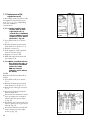
4.6 Mounting the boiler
4.6.1 Preparation (fig. 15)
Remove the boiler from the carton.
Lay the boiler on its back and remove
the four plastic sealing caps from
boiler flow and return and domestic
water connections.
On the connection group close the CH
service valves (8), unscrew the union
nuts (6) and remove plastic sealing
plugs.
fig. 15
VC/VCW 442/2
Slide the 22 mm nuts (6) and olives
(5) over the flow and return tails of the
boiler as far as possible. Fix these
temporarily in this position using tape
or similar.
fig. 16
GW 424/0
Close cold mains water service valve,
unscrew union nuts (4), remove and
discard plastic sealing plug. (Take
care not to lose sealing washers!)
4.6.2 Fitting the boiler (fig. 16)
Lift the boiler up to the wall so that it is
slightly above the connection group.
Lower the boiler slowly onto the
connection group so that:
• the flow and return tails of the boiler engage into the top of the CH
service valves
AND
• the cross member at the top rear of
the boiler slots into the hanging
bracket.
Remove the tape (or similar) used to
secure the nuts and olives on the flow
and return tails, slide these down onto
the CH service valves and tighten.
Align the cold and hot water connections with the boiler, fit the sealing
washers and tighten. (If necessary
adjust the position of the hot and
cold water connection pipes by loosening the locking nuts on the connection group).
18
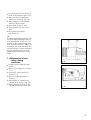
4.6.3 Gas supply (fig. 17)
The boiler is supplied with a 20 mm x
15 mm gas service valve (7). Fit the
20 mm compression fitting to the
boiler gas inlet (3) and tighten. Install
a gas supply pipe not less than 15 mm
diameter and connect to the gas service
valve. (Ensure the gas supply pipework
is adequately sized such that a 20 mbar
- 8" w.g. – gas pressure is available
at the boiler inlet at full flow rate).
Tighten all union connections.
4.6.4 Condensate discharge
(fig. 18)
The discharge pipe from the boiler
condensate drain must have a continous fall and preferably be installed
and terminated within the building to
prevent freezing.
The discharge pipe must terminate in
a suitable position, e.g.:a connecting into the internal stackpiO
pe of the property (at least 450 mm
above the invert of the stack). A
trap giving a water seal of at least
75 mm (3) should be incorporated
into the pipe run, and there must be
an air break (4) in the discharge
pipe upstream of the trap.
b
O connecting into the internal discharge system of the property such as a
sink or washing machine waste.
The connection should be upstream
of the sink / washing machine
waste trap. (If the connection is
downstream of the waste trap then
an additional trap giving a water
seal of at least 75 mm (3) and an
air break (4) must be incorporated
into the pipe run, as (a)).
c terminating in a gulley (5) below
O
grid level (6) and above the water
level.
fig. 17
GW 407/1
Insert the boiler condensate drain (1)
by at least 50 mm into a condensate
discharge pipe (2). The condensate
discharge pipe should be minimum
19 mm internal diameter and be
made of an acid resistant material
(e.g. plastic overflow pipe).
d at a condensate absorption point
O
fig. 18
GW 525/0
('soakaway')-7.
19
Refer to the British Gas publication
`Guidance notes for the installation of
domestic condensing boilers' for
further information.
Before operating the boiler the condensate trap on the boiler (1, fig. 19)
must be filled with water as described
in Section 5.6 `Filling condensate
trap'.
fig. 19
GW 411/1
Note:
If it is necessary to install any condensate pipework externally, then it
should be kept as short as possible,
be insulated with waterproof insulation and have a continuous fall of at
least 2.5 ° (i.e. 45mm fall for every
metre length).
(Note: Refer to the air/flue duct installation instructions for full details of
installation of the air flue duct. This
Section is included for further reference only, e.g. in case the boiler has
to be removed from the wall.)
fig. 20
GW 333/0
4.7 Connecting the flue
assembly to the boiler
4.7.1 Horizontal Flue
Place a 95 mm diameter x 88 mm
long air duct clamp (1, fig. 20) over
the air duct.
Push the sliding sleeve (1, fig. 21)
over the cut end of the flue duct.
20
fig. 21
GW 334/0
Line up the flue elbow socket with the
air/flue duct and pull back the sliding
sleeve so that it engages into the
socket of the flue elbow (fig. 22). The
sliding sleeve must penetrate the flue
elbow socket such that there is at least
20 mm engagement at both ends of
the sliding sleeve (fig. 23)
fig. 22
GW 335/0
Fit the flue elbow to the boiler by
inserting the spigot of the flue elbow
into the flue outlet socket of the boiler.
When correctly fitted the air duct of
the flue elbow should butt up to the
boiler air duct.
Ensure that the air/flue duct and terminal assembly is not displaced
through the wall, and that the terminal
assembly projects 90 mm as shown in
fig. 23.
Slide the 88 mm long air duct clamp
(5, fig. 24) back onto the elbow so
that it is located centrally over the
70mm gap between the elbow and
the flue assembly. Tighten the two
screws (2, fig. 24).
GW 336/0
Fit the 95 mm diameter x 25mm long
air duct clamp (4, fig. 24) over the
elbow and the boiler flue outlet spigot.
Tighten the two screws (1,fig. 24).
fig. 23
Screw the clamps to the air duct using
the sheet metal screws (3, fig. 24).
4.7.2 Vertical Flue
Lower the flue assembly and engage
the flue duct spigot into the socket of
the boiler flue outlet.
Fit the 55 mm long x 95 mm diameter
air duct clamp (3, fig. 26) over the
gap between the air duct of the boiler
and the bottom of the air/flue duct
and terminal assembly.
GW 337/0
With correct assembly there will be a
gap between the boiler and flue
assembly of 10 mm (fig. 25).
fig. 24
Tighten the clamp screws (1, fig. 26).
Note: The air duct clamp must not be
screwed to the bottom of the air flue
duct and terminal assembly. The
air/flue duct and terminal assembly
must be able to slide in the air duct
clamp to absorb any slight movements
in the roof structure.
fig. 25
GW 367/0
Secure the clamp to the boiler air duct
using the sheet metal screws provided
(2, fig. 26).
fig. 27
GW 360/0
fig. 26
GW 359/0
Ensure that the air/flue duct and terminal assembly is aligned vertically
and secure from inside using the
fixing bracket (1, fig. 27) over the
air/flue duct at a convenient position.
21
4.8 Electrical installation
4.8.1 General electrical
requirements
All electrical work shall be carried out
by a competent person and shall comply with the current edition of the IEE
regulations (BS7671).
fig. 28
GW 452/0
fig. 29
GW 453/0
Warning: This appliance must be
earthed
fig. 30
GW 527/0
The boiler is supplied for connection
to a 230V~ 50Hz supply fused at 3A
rating. Connection to the mains supply
should be made via a fused 3 pin
plug to an unswitched, shuttered
socket, both complying with the requirements of BS1363. (Alternatively,
connection may be made via a 3 Amp
fused double pole isolator having a
contact separation of at least 3mm in
all poles and supplying the boiler and
controls only).
The point of connection to the mains
should be readily accessible and
adjacent to the boiler. A 3 core flexible cord according to BS6500 tables
6, 8 or 16 (3x0.75 to 3x1.5 mm2)
should be used.
4.8.2 Connecting to mains
supply
Slacken front panel fixing screw
(1, fig. 28) and lower front panel.
Remove terminal box cover by undoing screws (1, fig. 29)
Connect the power supply cord as
follows:green / yellow (earth) wire
boiler terminal
Blue (neutral) wire...... boiler terminal N
Brown (live) wire...... boiler terminal L
NOTE: Do not use boiler terminal
connections 7-8-9!
To enable easier access to the wiring
terminals it is possible to lift the terminal strip (1, fig. 30) off the two
locating pins (2, fig. 30). After all
connections have been made, the
terminal strip must be relocated onto
the two pins.
22
→
→
→
→
4
4
L
3
N
L
1
4
3
→
N
3
→
ACL Drayton
Lifestyle
CT171, CT172,
PT271, PT371
2
2
3
4
4
→
1
→
→
L
→
N
→
→
L
ACL Drayton
PT110, PT170
→
→
1
N
2
3
OFF
ON
→
2
3
4
A
B
C
ON
OFF
→
Q2
→
→
5
→
4
Q1
→
3
2
4
→
3
Landis & Gyr
REV 10 and 21
3
→
1
→
Honeywell
CM51, CM41
4
4
→
3
Danfoss Randall
TP2, TP3, TP4, TP5
Potterton Myson
Pet 1
4
3
L
1
N
C
OFF
ON
fig. 31
L
4
→
L
→
N
N
L
1
2
→
1
→
3
3
3
3
5
E
N
L
3
E
5
6
4
3
2
2
3
ON
1
4
ON
4
→
L
2
4
→
2
OFF
6
OFF
4
→
N
5
ON
3
→
1
→
L
→
N
4
4
→
→
L
1
E
3
L
N
4
Danfoss Randall
103, 103E, 103E7
3
ON
→
L
2
OFF
4
→
N
4
→
2
L
→
Potterton Myson
EP400l, EP500l
3
→
1
N
N
4
4
→
L
3
→
N
4
4
ON
4
→
→
L
→
E
3
3
3
L
N
Landis & Gyr
RWB100, 152, 170
Danfoss Randall
Set 1E, TS975
2
3
Honeywell
ST7000B
(Battery operated)
Horstmann
425 Coronet
Channel Plus, H17, H11
2
→
Honeywell
ST6100
1
4
3
→
L
1
ON
→
N
ON
→
→
L
L
→
N
3
OFF
→
ACL Drayton
Switchmaster 300
(Please note: Remove Link N-2 and L-4)
N
4
2
→
1
N
3
→
→
L
Grässlin Towerchron
Dt71, T200l
L
→
→
N
→
N
→
ACL Drayton
Lifestyle
LP711
→
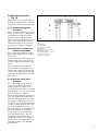
Connection details for external time switches and boiler terminal strip
4
5
ON
6
OFF
fig. 32
Boiler Terminal Strip
fig. 33
GW 409/0
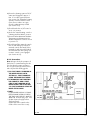
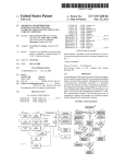
4.9.2.2 Connection details for external time switches and boiler terminal
strip.
Fig. 32 shows the connection details
where a time switch is used without a
room thermostat to control the boiler.
(Important: The arrowed numbers
indicate connection into the relevant
terminal in the boiler terminal strip).
If a room thermostat is to be connected in addition to a time switch the
wire between the time switch `ON'
terminal and boiler terminal 4 should
be broken by the contacts of the room
thermostat (see Schematic layout,
fig. 33)
3
2
3
→
4.9.2 Connection of external
electric controls
4.9.2.1 Connection details for programmable thermostat and boiler
terminal strip.
Fig. 31 shows the connection details
where a programmable thermostat
(time switch with built-in room thermostat) is used to control the boiler.
(Important: The arrowed numbers indicate connection into the relevant terminal in the boiler terminal strip).
L
1
ACL Drayton
Digistat 2 and 3
→
4.9.1 External electrical
controls
The boiler terminals 3,4 and 5 for
connecting external controls such as a
timeswitch and/or room thermostat.
Terminals 3 and 4 are linked together
when the boiler is supplied. If external
controls are used, this link (3, fig.30)
must be removed, and the controls
connected across terminals 3 and 4.
Terminal 5 is an additional neutral
connection for external neutrals such
as from the anticipator of a roomthermostat.
Refer to Section 4.9.2 for full connection details.
N
Vaillant Calotrol
(VRT 9083 and VRT 9084)
→
4.9 Controls
Connection details for programmable thermostat and boiler terminal strip
→
IMPORTANT Ensure that all cords
pass through the terminal box
entrance grommets and are securely
fixed by the cable clamps. Ensure that
the power supply cord is connected
such that the current carrying conductors become taut before the earthing
conductor should the supply cord slip
from the cable clamp.
Refit the terminal box cover after completition of all electrical connections.
23
4.9.3 Thermostatic radiator
valves
The boiler has a built-in automatic
bypass valve making it ideal for use in
systems with thermostatic radiator
valves (no separate system bypass is
required).
For optimum fuel economy it is recommended that where TRVs are used
they are used in conjunction with a
programmable roomstat or separate
timer and room thermostat to ensure
complete boiler shutdown when the
heating demand is satisfied. (The
radiator in the room containing the
room thermostat should not be fitted
with a TRV).
4.9.4 Frost protection
The boiler has an internal frost thermostat which is designed for protection of the boiler.
To protect remote or exposed parts of
the heating system or property additional frost protection measures must
be taken such as the installation of an
external frost thermostat. This frost
thermostat should be connected across
the boiler terminals 3 and 4, in parallel with any external heating controls.
4.9.5 Circulating pump
The boiler incorporates a built-in circulating pump that is fully pre-wired.
(No additional wiring is necessary).
The pump incorporates an automatic
overrun period after the boiler
switches off.
4.9.6 Anti-cycling `economiser'
control
The boiler incorporates a built in anticycling control to ensure that energy
wasteful short cycling of the boiler
cannot occur. This control prevents the
boiler from re-igniting for a pre-set
period of 5 minutes after central heating operation. (The hot water operation is unaffected by this control and
hot water can be drawn at any time).
(To temporarily override the anti-cycling control turn the central heating
control to the 'Hot Water only' position and then back to the 'Heating and
Hot Water' position.)
24
5. Commissioning
5.1 Preliminary electrical checks
Check the electrical installation by
carrying out short circuit, earth continuity and resistance to earth tests and
a check for correct polarity.
The complete gas installation including the gas meter must be inspected,
tested for soundness and purged in
accordance with BS 6891.
fig. 34
GW 410/0
5.2 Gas supply
The gas supply to the boiler can be
purged by slackening the gas service
valve beneath the boiler (1, fig. 34).
Ensure that there is adequate ventilation, extinguish naked flames and do
not smoke whilst purging.
After purging, the gas service valve
connection must be re-tightened and
tested for soundness.
(The boiler itself does not require purging as this will be done by the automatic burner sequence control).
5.3 Water supply
Open all domestic hot water taps supplied by the boiler, turn on the mains
water supply to the boiler and open
the mains water isolating valve below
the boiler (2, fig. 34).
Water will now flow through the boiler to the hot taps. Starting with the
lowest tap supplied, turn the hot taps
off one at a time until the hot water
pipework is purged of air.
Check all hot and cold pipework for
leaks.
25
5.4 Filling the heating system
The boiler primary circuit and the heating system should be filled using a filling method as described in Section
3.7.2.
Partially open the filling valve and
allow water to enter the system. Starting with the lowest radiator, open the
radiator air release until water (clear
of bubbles) is emitted.
Repeat this at all radiators until the
complete system is full, all air locks
have been cleared and the boiler
pressure gauge reads 1.5 Bar.
Release any air from the pump by
slackening the centre screw (3, fig.
35).
The boiler is equipped with an automatic air release valve. To allow this
to vent the boiler, the cap on top (2,
fig. 35) must be slackened by 1-2
turns. (This cap must be left slackened
during boiler operation to ensure any
residual air or system gases are released).
Check the heating system and boiler
connections are sound.
5.5 Initial system flush ('cold')
The whole of the heating system must
be flushed out at least twice: once
cold, and once hot as instructed later
in Section 5.13.
Open all radiator or heating valves
and boiler CH service valves and
drain the heating system and boiler
completely from the lowest points of
the system via 1/2” BSP drain taps
(opened full bore to remove any installation debris prior to lighting the boiler).
Refill the heating system as described
in Section 5.4: Filling the heating
system.
Check the operation of the pressure
relief valve by rotating the knob on
the valve.
26
fig. 35
GW 411/1
Ensure that the boiler CH service
valves (3, fig. 34) are open.
5.6 Filling condensate trap
Remove the lower part of the condensate trap (1, fig. 35) by unscrewing
and fill with water to about 10 mm
from the top. Refit in boiler.
5.7 Initial lighting
fig. 36
fig. 37
GW 407/0
chamber (5, fig. 36) is correctly
fitted.
• Ensure the cold water shut-off valve
(13, fig. 37) is open by turning
anti-clockwise.
• Open the gas service valve
(7, fig. 37)
• Check that the CH service valves
(6 and 15, fig. 37) are open.
• Check that all external heating
controls are calling for heat.
• Switch on the electricity supply to
the boiler.
• Set both the maximum hot water
temperature control (4, fig. 36) and
maximum radiator temperature
control (3, fig. 36) to `9'.
• Turn the boiler on/off control
(1, fig. 36) to `on'.
• Set the boiler central heating
control (2, fig. 36) to the `Heating
and Hot Water' position.
The boiler will now operate for central
heating. Allow the boiler to run for a
few minutes to clear any air remaining
in the primary circuit.
(If the boiler should fail to light the diagnostic display - 8, fig. 36- will indicate fault code F:21. This usually indicates that the gas supply is turned off,
or is not purged of air. Check gas
supply, push red `Reset' button on
front of control panel - 10, fig. 36 and repeat lighting procedure).
GW 495/0
• Check that the boiler combustion
• Set the boiler central heating con-
trol to the `Hot Water only' position. The boiler will now switch off.
• FULLY open a hot water tap. The
boiler will now operate for hot
water.
At this point the maximum domestic
hot water flow rate can be adjusted if
required.
27
fig. 38
GW 458/0
NOTE: The water flow limiter built into
the boiler ensures that the maximum
domestic hot water flow rate does not
exceed the nominal setting (equivalent
to a hot water temperature rise of
35 °C). Adjustment is only required if
the user requires a higher temperature
rise than this setting.
Turn the water flow adjusting screw
(2, fig. 38) clockwise to decrease the
flow from the tap until the temperature
rise is at the desired level. Turn off the
hot tap after completion of adjustment.
5.8 Gas inlet working pressure
fig. 39
GW 412/0
Check the gas inlet working pressure
by slackening the sealing screw and
attaching a U gauge to the inlet test
point on the gas valve marked `PE'.
Fire the boiler at full rate by opening
a hot water tap. Check that the U
gauge is reading 20 mbar.
(If the pressure is not 20mbar this
should be investigated before continuing with the commissioning procedure. Lower pressures than 20mbar
are indicative of an incorrectly sized
or partially blocked gas supply).
Turn off the hot tap. Remove U gauge.
Tighten the test point screw and test
for soundness.
fig. 40
GW 459/0
(fig. 39)
5.9 Adjusting the central
heating output
(range rating)
ECOmax is fully modulating for
central heating, and it is therefore not
necessary to range rate the central
heating. The boiler operates at very
high efficiency across its heat output
range. However, even greater
efficiency may be obtained by range
rating the boiler, as follows:• Put the boiler into diagnostic mode
by pushing the two buttons below
the boiler display simultaneously
until a `d' code is displayed
(1 and 2, fig. 40).
(For further information on how to
use the boiler display refer to
Section 8: Fault Finding)
• If code `d. 0' is not displayed, push
the left hand button to step through
the various D codes until the screen
shows the `d. 0' code
28
•
•
•
•
•
5.10 Main burner pressure
The burner pressure on this boiler has
been factory set and does not require
adjustment. The main burner pressure
may be checked in the following way:
• Ensure the maximum hot water
temperature control (4, fig. 36) is
set to ’9’.
• Fully open a hot water tap to fire
the boiler at full rate.
• Put the boiler into diagnostic mode
by pushing the two buttons (1 and
2, fig. 40) below the diagnostic display simultaneously until a `d' code
is displayed.
• Push the left hand button to step
through the various `d' codes until
the screen shows the `d.20' code.
• Push the right hand button once.
The display will now show the main
burner pressure in Pascals
(100 Pa = 1 mbar).
• Check that the burner pressure is as
shown in Table 5. (If the burner
pressure is not correct within the
tolerance shown contact Vaillant
Ltd. Technical Department).
• Turn off the hot tap.
fig. 41
GW 455/0
•
The display will now show the percentage range rating of the central
heating (compared to the maximum
nominal output for domestic hot
water). (Note: The factory set maximum figure is 80)
Remove screw (1, fig. 41) and
lower control panel.
Remove cover screw (2, fig. 42) to
access the range rating potentiometer beneath.
The central heating output can now
be altered by inserting an electricians screwdriver into the potentiometer and turning. (See Table 4 for
the required output settings).
The selected rating will be displayed on the boiler display as adjustments are made.
After setting, refit cover screw (2,
fig. 42) and resecure control panel
(1, fig. 41).
Push both buttons under the boiler
display simultaneously. The flow
temperature will now be displayed.
GW 452/0
• Push the right hand button once.
fig. 42
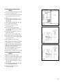
Table 4: Central Heating Output (Range Rating)
Range rating
Output to Central Heating kW (Btu/h)
(Diagnostic Code
(with return temperature = 60 °C)
d. Ø reading)
VUW 236 E
VUW 286 E
80 (Maximum)
17.2 (58,700)
21.3 (72,700)
70
15.1 (51,500)
18.6 (63,500)
60
12.9 (44,000)
16.0 (54,600)
50
10.8 (36,800)
13.3 (45,400)
47 (Minimum)
9.9 (33,800)
12.3 (42,00)
Table 5: Burner Pressure & Gas Rate
Maximum Burner
Pressure (DHW)
(d. 20 reading)
Maximum Gas
Rate (DHW)
VUW 236 E
VUW 286 E
300 Pa ± 30 Pa
300 Pa ± 30 Pa
2.38 m3/h
2.96 m3/h
(84.04 ft3/h)
(104.52 ft3/h)
29
• Push both buttons under the diag-
nostic display simultaneously.
The flow temperature will now be
displayed.
• Reset the maximum hot water temperature selector to the required
setting (see Section 5.15).
5.11.1 Introduction
The boiler display (8, fig. 43) normally indicates the primary flow temperature. Whilst this display is showing the
boiler has internally self checked and
is operating normally. However, if
desired, a functional check of the boiler DHW and CH operation may be
carried out using the status mode of
the built in diagnostics.
5.11.2 Functional check of
DHW operation using
built in diagnostics
• Set the boiler central heating control to the `Hot Water only' position
• Enter status mode by pushing the
right hand diagnostic button once,
e.g. with the tip of a ballpoint pen
(1, fig. 43). The display should
now show `S.0'
• Turn on a hot tap and draw water
at a high rate.
• The display will now step through
the following codes:
• S.10 - calling for operation: DHW.
(display duration: 1 sec)
• S.11 - fan running and proving
(display duration: 4 -5 secs)
• S.13 - ignition
(display duration: 10 secs max)
• S.14 - burner operation: DHW
(display for duration of hot water
draw off)
• Turn the hot water tap off. The burner should be extinguished and the
display will now step through the
following codes:
• S.15 - pump and fan overrun
(display duration: 5 secs)
30
fig. 43
GW 459/0
5.11 Functional checks
• S.17 - pump overrun
•
(display duration: 20 secs to
80 secs)
S.0 - no water demand
By stepping correctly through these
codes the boiler has demonstrated
correct functioning for DHW.
To exit from status mode push the right
hand button once. (The display will
now show the primary flow temperature).
5.11.3 Functional check of CH
operation using built in
diagnostics
• Set the boiler central heating control to the `Heating and Hot Water'
position.
• Enter status mode by pushing the
right hand diagnostic button once,
e.g. with the tip of a ballpoint pen
(1, fig. 43). The display should
now show `S.0'
• Turn on all external controls (room
thermostat, timer etc.) and turn
maximum radiator temperature
control to `9'
• The display will now step through
the following codes:
• S.1 - fan running and proving
(display duration: 4 -5 secs)
• S.3 - ignition
(display duration: 10 secs max)
• S.4 - burner operation CH
(display for duration of CH operation)
• Turn the external heating controls
off. The burner should be extinguished and the display will now step
through the following codes:
• S.5 - pump and fan overrun
(display duration: 5 secs)
• S.7 (pump overrun)
(display duration: 20 secs to
5 mins)
• S 30 (external controls satisfied)
• Turn the external central heating
controls on. The following code will
now be displayed:
• S.8 (anti-cycling `economiser'
engaged)
(display duration: 5 mins)
31
(Note: This control ensures that energy
wasteful short-cycling of the boiler
cannot occur, by preventing the boiler
from igniting for a preset period of 5
minutes after central heating operation. The hot water operation is unaffected by this control and hot water
can be drawn at any time. To temporarily override the anti-cycling control turn the central heating control to
the `Hot Water only' position and
then back to the `Heating and Hot
Water' position).
By stepping correctly through these
codes the boiler has demonstrated
correct functioning.
To exit from status mode push the right
hand button once. (The display will
now show the primary flow temperature).
• Reset the maximum radiator
temperature control to the required
setting according to Section 5.15.
(For further information on how to use
the boiler display refer to Section 8:
Fault Finding).
5.12 Checking flame supervision device
Operate boiler and turn off gas supply
at boiler gas service valve. The boiler
should attempt to relight (sparking at
ignition electrode visible through viewing window) for approximately
10 seconds before shutting down.
Fault code F.21 will then be displayed
on the control panel display. Open
the gas service valve and press the
reset button (10, fig. 36). The boiler
should now relight.
32
5.13 Final system flush (`hot')
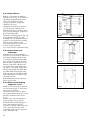
5.15 Hand over to user
Allow the boiler and system to reach
maximum temperature and check that
the heating system is watertight. Turn
the boiler off and rapidly drain both
boiler and system while still hot.
Refill the system and release all air as
described in Section 5.4. Release
water from the system until the system
design pressure of 1.2 bar is attained.
(The actual reading on the pressure
gauge - 12, fig. 36 - should ideally be
0.5 Bar plus an additional pressure
corresponding to the highest point of
the system above the base of the boiler - 10 m head equals an additional
1 Bar reading on the pressure gauge.
The minimum pressure should not be
less than 1 Bar in any installation).
If the system is to be treated with an
inhibitor it should be applied at this
stage. Sentinel X100 is suitable for
this purpose and should be applied in
accordance with the manufacturers
instructions.
Further information can be obtained
from Sentinel, Grace Dearbom Ltd,
Tel: 0151 495 1861.
(The boiler does not utilise aluminium
in the water system and it is therefore
not necessary to use any special
inhibitors in the system.)
Disconnect the temporary filling
connection.
Set the maximum hot water temperature control to the required setting.
(For normal circumstances the maximum hot water temperature should be
set between 7 and 9. In hard water
areas the formation of scale in the hot
water system may be minimized by
not tuning the control above the ” ”
symbol).
Set the maximum radiator temperature
control to the required setting.
Attach top door panel by slotting side
clips (1, fig. 44) into holes in side
panel and sliding panel down to
secure.
Attach bottom door panel by locating
onto top hinge pin (4, fig. 45) and
inserting bottom hinge screw (3, fig.
45) down so that it also locates into
the door.
Instruct the user in the safe and efficient operation of the boiler, in particular the function of:• the boiler on / off control
• the maximum radiator temperature
control
• the maximum hot water temperature
control
• the pressure gauge.
fig. 44
GW 438/0
Note: Operating the boiler at a lower
setting will increase fuel saving. However, if the setting is too low then the
radiators may not reach the desired
temperature. For maximum fuel saving
under normal circumstances the following settings may be used as a guide:
Spring and Autumn
5–6
Winter (normal)
6–7
Winter (severe)
7–9
Advise the user that the boiler has an
internal frost protection thermostat,
and in very cold weather may therefore operate automatically to prevent
damage to itself.
Show the user how to operate any
external controls.
Explain to the user the importance of
having the boiler regularly serviced
annually by a qualified servicing company. To ensure regular servicing, it is
strongly recommended that arrangements are made for a Maintenance
Agreement. Please contact Vaillant
Service Department (FREEPHONE
0800 318076) for further details.
fig. 45
GW 459/0
5.14 Fitting case
t
Leave the user instructions in the purpose provided pocket on the front of
the control panel (5, fig 46).
Leave the installation and service
instructions with the user.
33
To ensure the continued safe and efficient operation of the boiler it is
recommended that it is checked and
serviced as necessary at regular
intervals. The frequency of servicing
will depend upon the particular installation conditions and usage, but in
general once per year should be adequate. It is law that all servicing work
is carried out by a competent person
(Corgi registered).
IMPORTANT:
Before starting any maintenance
work:
• Isolate the mains electricity supply
by disconnecting the plug at the
socket outlet (if there is an isolating
switch only remove the fuse from
the switch).
• Turn OFF the gas supply at the gas
•
•
service valve fitted to the boiler.
Always test for gas soundness and
always carry out functional checks
after any service work and after
exchanging any gas carrying
component.
Always check earth continuity,
polarity and resistance to earth with
a multimeter after any service work
and after exchanging any electrical component.
Note: The boiler is fitted with a
combustion analysis test point. A
suitable combustion analyser can be
connected to this point to establish
the combustion performance of the
boiler.
34
fig. 46
GW 413/0
6. Servicing
6.1 Initial Inspection
Before commencing any servicing or
maintenance work, carry out an initial
inspection of the system as follows:-
Inspect the air supply and ventilation
arrangements of the installation, ensuring that the requirements of Section
3.5 are met.
Operate the boiler by turning the
maximum hot water temperature control (4, fig. 47) to `9' and fully opening a hot water tap. Inspect the
burner operation through the viewing
window. Check that the flames are
burning evenly over the full surface of
the burner. Inspect for signs of excessive lifting or sooting.
fig. 47
GW 419/0
Inspect the flue, pipework and electrical connections for indications of
damage or deterioration.
Check the heating and hot water
system, in particular the condition of
the radiator valves, evidence of leakage from the heating system and
dripping hot water taps.
6.1.1 Functional checks of
operation using the built
in diagnostics
Refer to Section 5.11 for information
on using the diagnostic feature to perform functional checks on the boiler.
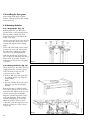
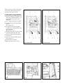
6.2.1 Turn off the boiler
(fig. 48)
• Isolate the electrical supply to the
boiler
• Turn off the gas service valve (1)
• Turn off boiler CH service valves (2)
• Turn off DHW cold water service
valve (3).
fig. 48
GW 414/0
6.2 Routine maintenance
6.2.2 Remove front case
Remove bottom hinge screw (3, fig.
49) and pull the bottom door panel
forward and down to release it from
the top hinge pin (4, fig. 49).
Slide the top panel up to release retaining clips (1, fig. 50). Lift off top
panel.
35
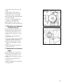
6.2.5 Check central heating
expansion vessel
NOTE: It is not necessary to perform
this check every year - a check every
three years is sufficient.
Close the boiler CH service valves
(2, fig. 48). Release the pressure from
the boiler as described in Section
7.1.2.
Remove valve cap from expansion
vessel charge point (2, fig. 55).
Check that the internal charge pressure of the expansion vessel is
between 0.7 and 0.9 Bar. If the pressure is lower than this the vessel
should be repressurised using an air
pump. Refit valve cap.
36
GW 459/0
fig. 50
GW 438/0
6.2.4 Inspect main heat
exchanger
With the burner / fan assembly removed it is now possible to inspect the
main heat exchanger. Remove any
loose deposits from the heat exchanger, using a brush and jet of water.
(Ensure water is kept away from all
eletrical components.) Remove the
lower part of the condensate trap (1,
fig. 54) by unscrewing. Empty and
clean (ensuring that any debris that
has fallen while cleaning the main
heat exchanger is removed) and fill
with water to about 10 mm from the
top. Refit in boiler.
Reassemble burner and combustion
fan in reverse order.
fig. 49
fig. 51
GW 423/0
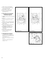
6.2.3 Inspect burner
Remove 5 combustion chamber retaining screws (3, fig. 51). Slacken 2
side panel spring retaining screws
(2, fig. 51) and remove screw
(4, fig. 51). Remove combustion
chamber front cover.
Unplug the 2 electrical connections
(1, fig. 52) from combustion fan.
Remove the 2 burner retaining clips
(6, fig. 52) by lifting top of clip off of
burner mounting plate.
The burner mounting plate (5, fig. 52)
and combustion fan (4, fig. 52)
assembly can now be removed by lifting the front of the burner mounting
plate up, and pulling forward.
The ceramic burner (2, fig. 53) can
now be visually inspected.
(It is not necessary to clean the burner).
Open CH service valves, and repressurise boiler and heating system if
necessary (see Section 5.4).
6.3 Recommisioning the boiler
•
•
•
•
fig. 53
GW 493/0
fig. 52 (Natural Gas)
fig. 54
fig. 52a (Propane)
fig. 55
GW 1284/0
•
GW 468/0
•
GW 411/1
•
•
cover. Ensure that the panel is correctly fitted and a good seal is
obtained.
Turn on gas and electrical supply.
Operate burner and check flame
picture.
(see Section 6.1)
Check boiler functioning either
visually or by using the built-in diagnostic feature
(see Section 5.11)
Check burner pressure (see Section
5.10) and boiler gas flow rate.
Check soundness of internal gas
connections.
Carry out electrical safety checks
(see Section 5.1)
Check water soundness
Refit case (see Section 5.14)
GW 422/0
• Refit the combustion chamber front
37
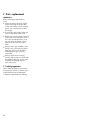
7. Parts replacement
IMPORTANT:
Before starting any maintenance
work:
• Isolate the mains electricity supply
by disconnecting the plug at the
socket outlet (if there is an isolating
switch only, remove the fuse from
the switch).
• Turn OFF the gas supply at the gas
service valve fitted to the boiler.
• When removing any water carrying
components ensure that the control
box cover and terminal box cover
are in position and water is kept
away from all electrical components.
• Always test for gas soundness and
•
always carry out functional checks
after any service work and after
exchanging any gas carrying
component.
Always check earth continuity,
polarity and resistance to earth with
a multimeter after any service work
and after exchanging any electrical component.
7.1 Initial preparation
(These initial preparation procedures
need only be carried out where specifically mentioned in the individual
component replacement procedures).
38
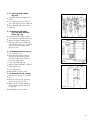
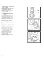
7.1.3 Removal of front casing
7.1.3.1 Door (fig. 57)
• Remove bottom hinge screw (3)
and pull the bottom door panel
forwards and down to release it
from top hinge pin (4).
fig. 56
fig. 57
GW 459/0
7.1.2 Releasing CH water
pressure and draining
boiler (fig. 56)
Isolate
electrical supply to boiler.
•
• Turn off boiler CH service valves (2).
• Attach a length of rubber tube to
draining points (4), and drain the
water from the boiler into a suitable
container by undoing the drain
points one turn.
GW 415/0
7.1.1 Turning off the boiler
(fig. 56)
Isolate
the electrical supply to the
•
boiler
• Turn off the gas service valve (1)
• Turn off boiler CH service valves (2)
• Turn off DHW cold water service
valve (3).
7.1.3.2 Top panel (fig. 58)
• Slide top panel upwards to release
retaining clips (1).
7.1.4 Removal of side casings
• Remove front casing as in Section
7.1.3.
• Remove screws (3, fig. 58) and
slacken screws (2, fig. 59).
• Slide side case panel upwards to
release retaining clips and lift off
(2, fig. 58).
• Reassemble in reverse order
fig. 58
GW 438/0
7.1.3.3 Reassembly
• Reassemble in reverse order.
39
fig. 59
GW 423/0
7.1.5 Removal of combustion
chamber cover (fig. 59).
Remove
front casing as in Section
•
7.1.3,
• Slacken the 2 case retaining screws
(2).
• Undo the 5 captive inner casing
screws (3).
• Remove screw (4).
• Lift combustion chamber cover (5)
off boiler.
• Check condition of case seal, and
if necessary replace before refitting.
• Reassemble in reverse order, ensuring that the cover case is correctly fitted and a good seal obtained.
7.2 Replacement of fan
• Isolate the boiler from the electrical
•
•
•
•
•
•
•
fig. 61 (Natural Gas)
40
fig. 61a (Propane)
GW 1284/0
•
supply.
Remove front casing as in Section
7.1.3, and remove combustion
chamber cover as in Section 7.1.5.
Disconnect the 2 plug-in fan
connections (1, fig. 7.3).
Remove the 2 fan securing bolts
(7, fig. 61).
Remove fan inlet restrictor
(3, fig. 61) and fit to new fan.
Remove fan.
Replace fan mounting gasket
(1, fig. 62) with new gasket supplied with fan.
Reassemble in reverse order,
making sure that the 2 fan securing
bolts are fully tightened.
Re-fit combustion chamber and front
casing.
Carry out electrical checks
(see Section 5.1).
GW 422/0
•
fig. 60
GW 452/0
7.1.6 Lower front control panel
(fig. 60)
Remove
front casing as in Section
•
7.1.3,
• Undo screw (1) and lower control
box forward from top.
7.3 Replacement of air pressure
sensor (fig. 63)
•
•
•
•
•
supply.
Remove front casing as in Section
7.1.3.
Disconnect plug (3) from air pressure sensor.
Pull the front of the air pressure
sensor (1) down to release from
gas valve (2) and remove by
unhooking from rear retaining clip.
Replace in reverse order.
Carry out electrical checks
(see Section 5.1).
fig. 62
GW 460/0
• Isolate the boiler from the electrical
7.4 Replacement of burner
•
•
•
•
•
•
supply.
Remove front casing as in Section
7.1.3.
Remove combustion chamber cover
as in Section 7.1.5.
Remove the 2 burner retaining
springs (6, fig. 64) by lifting the top
of the spring up and pulling forward.
Disconnect the 2 fan electrical
connections (1, fig. 64).
Slide the fan inlet restrictor (3,
fig. 64) top the right to separate
from the fan.
Remove complete burner and fan
assembly by lifting the burner plate
(2, fig. 64) at the front and pulling
forward to disengage burner from
a spring clip at the rear.
fig. 63
GW 461/0
• Isolate the boiler from the electrical
• Remove burner plate from fan
fig. 64a (Propane)
GW 1284/0
fig. 64 (Natural Gas)
GW 422/0
assembly by removing the 2 bolts
(5, fig. 64).
• Inspect fan gasket (1, fig. 62) and
replace if worn or broken.
- Reassemble in reverse order.
• Carry out electrical checks (see
Section 5.1) and check burner
pressure (see Section 5.10) and
gas rate.
41
7.5 Replacement of electrodes
• Isolate the boiler for the electrical
7.5.2 Flame sensing electrode
(fig. 66).
• Pull off sensing wire (1).
• Remove two retaining nuts (2).
• Remove electrode (3).
• Fit new sealing gasket supplied
with electrode.
• Replace electrode.
• Reassemble in reverse order.
• Carry out electrical checks
(see Section 5.1).
42
fig. 65
fig. 66
GW 462/0
7.5.1 Ignition electrodes
(fig. 65).
• Pull off HT lead (1)
• Pull off earth wire (2).
• Remove the 2 retaining nuts (3).
• Remove ignition electrodes (4).
• Fit new sealing gasket supplied
with electrode.
• Replace electrode.
• Reassemble in reverse order.
• Carry out electrical checks
(see Section 5.1).
GW 463/1
•
supply.
Remove front casing as in Section
7.1.3, and remove combustion
chamber cover as in Section 7.1.5
7.6 Replacement of condensate
sump
•
•
•
•
fig. 67
fig. 68 (Natural Gas)
fig. 68a (Propane)
fig. 69
GW 1284/0
•
GW 434/0
•
GW 422/0
•
supply.
Remove front casing as in Section
7.1.3 and remove combustion
chamber cover as in Section 7.1.5
Pull the condensate sump retaining
clip (1, fig. 67) forward to release
sump.
Remove two securing clips (6, fig.
68) by pulling the top of the
securing clip up and forward.
Rotate sump draw handle (2, fig.
67) until it is pointing forward, then
slide it down into the condensate
trap (3, fig. 67) clear of the sump.
Remove sump by pulling it down at
the front and forward.
Check gaskets (1, fig. 69) before
replacing.
Replace in reverse order.
GW 464/1
• Isolate the boiler from the electrical
43
7.7 Replacement of condensate
trap (fig. 70)
•
•
•
fig. 70
GW 465/0
•
supply.
Remove front casing as in Section
7.1.3, remove combustion chamber
cover as in Section 7.1.5 and
lower front control panel as in
Section 7.1.6
Undo the 2 unions (1) and pull trap
down to remove from boiler.
Fill condensate trap with water to
about 10 mm from the top before
replacing.
Reassemble in reverse order using
spare `O' rings supplied.
fig. 71a (Propane)
GW 1285/0
• Isolate boiler from the electricity
7.8 Replacement of temperature
sensors (NTCs) (fig. 71).
•
•
•
•
•
•
supply.
Remove front casing as in Section
7.1.3 and remove combustion
chamber cover as in Section 7.1.5
Identify sensor(s) to be replaced.
Pull off connecting wire to sensor.
Unscrew NTC sensor.
Replace using contact paste
supplied
Assemble in reverse order.
fig. 71 (Natural Gas)
GW 427/0
• Disconnect boiler from electricity
7.9 Replacement of gas valve
(fig. 72)
•
•
•
•
•
•
•
supply.
Turn off the gas service valve.
Remove front casing as in Section
7.1.1
Undo screw (3) and pull off solenoid electrical connecting plug.
Undo the 4 screws (1).
Pull gas valve forward to remove.
Reassemble in reverse order using
cork gasket supplied.
Carry out electrical checks (see Section 5.1) and gas soundness tests
(see Section 5.2), and check burner
pressure (see Section 5.10) and
gas rate.
44
fig. 72
GW 437/0
• Isolate the boiler from the electrical
7.10 Replacement of main heat
exchanger
•
•
•
•
•
•
•
•
•
fig. 73 (Natural Gas)
fig. 73a (Propane)
fig. 74
fig. 75
GW 1286/0
•
GW 466/1
•
GW 467/0
•
7.1.1.
Release CH water pressure and
drain boiler as in Section 7.1.2.
Remove front casing as in Section
7.1.3 and remove combustion
chamber cover as in Section 7.1.5
Remove fan and burner assembly
as in Section 7.4.
Remove condensate sump as in
Section 7.6.
Pull off wires from heat exchanger
NTC (1, fig. 73), ignition electrode
(2, fig. 73) sensing electrode (3,
fig. 73) and earth wire (4, fig. 73).
Remove screw (5, fig. 73) and wire
from heat exchanger connecting
pipe.
Pull off the 2 wire pipe retaining
clips (1, fig. 74).
Undo the 4 nuts (1, fig. 75).
Pull pipe (2, fig. 74) forward to
release from heat exchanger.
Pull pipe (3, fig. 74) to the right
and remove heat exchanger.
Reassemble in reverse order.
Recommision boiler (see Section 5).
GW 428/0
• Turn off the boiler as in Section
45
7.11 Replacement of CH
expansion vessel
7.11.1. Boiler installed with
air/flue duct to left/right hand side, or
vertical flue installation
(where 600mm vertical
clearance exists above
the boiler) - fig. 76
Turn
off
the boiler as in Section
•
7.1.1.
• Release CH water pressure and
drain boiler as in Section 7.1.2.
• Slacken 2 screws (1).
• Slide expansion vessel upwards
and out of boiler casing.
• Replace in reverse order.
• Refill and repressurise the boiler
(see Section 5.4).
fig. 76
GW 468/0
In the unlikely event of a failure of the
CH expansion vessel follow procedure 7.11.1 or 7.11.2 depending
upon the installation
circumstances.
7.11.2 Boiler installed with air
flue duct to the rear, or
vertical flue installation
(where less than
600 mm vertical
clearance exists above
the boiler)
EITHER
Remove the boiler front the wall as
follows:
•
•
•
•
•
•
7.1.1.
Release CH water pressure and
drain boiler as in Section 7.1.2.
Remove front casing as in Section
7.1.3
Disconnect external wiring from
boiler terminal box.
Disconnect flow and return connections at compression connection
above boiler CH service valves
(1, fig. 77).
Disconnect gas connection at compression joint on top of gas service
valve (2, fig. 77).
Disconnect domestic hot and cold
water connections on the water
section (3, fig. 77).
46
fig. 77
GW 416/0
• Turn off the boiler as in Section
• Disconnect the flue from the top of
•
•
•
•
•
boiler as described in Section 4.7.
Remove boiler from wall and
slacken two screws (1, fig. 76).
Slide expansion vessel upwards
and out of boiler casing.
Reassemble in reverse order.
Re-mount the boiler (see Section
4.6).
Re-commission the boiler
(see Section 5).
7.12 Replacement of main
safety isolating
transformer
fig. 78
GW 455/0
OR
A suitable replacement expansion vessel can be fitted externally to the boiler as described in Section 3.7.5 (if
possible on the central heating return
in an accessible position). In these circumstances, the replacement expansion vessel must be correctly sized ignoring the original expansion vessel
which can be left in position on the
boiler.
•
•
•
•
•
supply.
Remove front casing as in Section
7.1.3
Lower front control panel as in
Section 7.1.6.
Remove condensate trap as in
Section 7.7.
Remove back of control box by
undoing the 2 screws (1, fig. 78).
Unplug transformer plugs (1, fig.
79) and remove from control box.
fig. 79
GW 436/0
• Isolate boiler from the electricity
47
• Undo screws (7, fig. 80) and
•
•
remove transformer by pulling it
down and to the right.
Reassemble in reverse order.
Carry out electrical checks
(see Section 5.1).
7.13 Replacement of ignition
transformer (fig. 81)
fig. 80a (Propane)
GW 1287/0
fig. 80 (Natural Gas)
fig. 81
GW 496/0
supply.
• Remove front casing as in Section
7.1.3.
• Lower front panel as in Section
7.1.6.
• Remove screw (1) and slide spark
generator forward to release from
boiler chassis.
• Disconnect leads by undoing two
cable grips (2) and pull out.
• Pull off mains connection cover
(3) and disconnect electrical
connections.
• Reassemble in reverse order.
- Carry out electrical checks
(see Section 5.1).
GW 526/0
• Isolate the boiler from the electricity
7.14 Replacement of pump
- Turn boiler off as in Section 7.1.1.
- Release pressure and drain boiler
as in Section 7.1.2.
- Remove front casing as in Section
7.1.3.
- Lower front control panel as in
Section 7.1.6.
48
•
•
•
•
•
•
82).
Pull pump forward to remove.
Remove back of control box by
undoing 2 screws (1, fig. 78).
Disconnect pump supply plug and
lift clear of board.
Fit new `0' rings (supplied with
pump) to connecting tubes.
Reassemble in reverse order.
Recommision boiler (see Section 5).
7.15 Replacement of automatic
air release (fig. 82)
fig. 82
GW 469/0
• Undo the 3 pump screws (3, fig.
•
•
•
•
•
drain boiler as in Section 7.1.2.
Remove front casing as in Section
7.1.3.
Lower front control panel as in
Section 7.1.6.
Unscrew cap (4) of auto air release
and remove inner components.
Replace with new inner components and reassemble in reverse
order.
Refill and repressurise the boiler
(see Section 5.4).
fig. 83
GW 470/0
• Turn off boiler as in Section 7.1.1.
• Release CH water pressure and
7.16 Replacement of automatic
bypass
• Turn off boiler as in Section 7.1.1.
• Release CH water pressure and
•
drain boiler as in Section 7.1.2.
Remove front casing as in Section
7.1.3.
• Lower front control panel as in
•
Section 7.1.6.
Remove spring clip (2, fig. 83) by
lifting upwards.
49
• Undo union (1, fig. 84) and remove
•
•
bypass (2, fig. 84).
Reassemble in reverse order using
sealing washers supplied.
Refill and repressurise the boiler
(see Section 5.4).
•
•
•
•
•
•
•
•
•
fig. 84
fig. 85
fig. 86
50
GW 496/0
•
drain boiler as in Section 7.1.2.
Remove front casing as in Section
7.1.3.
Lower front control panel as in
Section 7.1.6.
Remove screw (1, fig. 85) and lift
ignition transformer clear of diverter
valve.
Remove tube (1, fig. 86) by pulling
to left.
Remove four screws (2, fig. 86)
Pull diverter valve to remove.
Remove diverter valve operating
solenoid cover (3, fig. 86) and
disconnect solenoid wires.
Reassemble in reverse order.
Carry out electrical checks
(see Section 5.1).
Refill and repressurise the boiler
(see Section 5.4).
GW 477/0
• Turn off boiler as in Section 7.1.1.
• Release CH water pressure and
GW 471/0
7.17 Replacement of diverter
valve
fig. 87
GW 472/0
7.17.1 Replacement of diverter
valve diaphragm
(fig. 87).
Remove
diverter valve as in Section
•
7.17
• Remove the 4 screws (1).
• Lift top off diverter valve and remove diaphragm.
• Replace in reverse order.
• Carry out electrical checks
(see Section 5.1).
• Refill and repressurise the boiler
(see Section 5.4).
7.18 Replacement of pressure
gauge (fig. 88)
•
•
•
•
•
drain boiler as in Section 7.1.2.
Remove front casing as in Section
7.1.3.
Lower front control panel as in
Section 7.1.6.
Undo union (1) at rear of pressure
gauge, depress side springs on
pressure gauge with a screwdriver
and pull forward to remove.
Replace in reverse order.
Refill and repressurise the boiler
(see Section 5.4).
fig. 88
GW 473/0
• Turn off boiler as in Section 7.1.1.
• Release CH water pressure and
7.19 Replacement of water
section
•
•
•
•
supply.
Turn off mains water isolating valve
and open a hot tap.
Remove front casing as in Section
7.1.3.
Lower front control panel as in
Section 7.1.6.
Undo union (1, fig. 89) remove
spring clip (1, fig. 90) by lifting,
pull pipe (2, fig. 90) forward and
remove.
fig. 89
GW 458/0
• Isolate boiler from the mains
51
•
•
•
7.19.1 Change of water section
diaphragm (fig. 91)
• Remove water section as in Section
7.19.
• Remove the 6 screws (1), and lift
water section cover.
• Remove diaphragm.
• Reassemble in reverse order.
• Carry out electrical checks
(see Section 5.1).
• Refill and repressurise the boiler
(see Section 5.4).
7.20 Replacement of DHW
microswitch (fig. 90).
• Isolate appliance from electricity
•
•
•
•
•
•
•
supply.
Remove front casing as in Section
7.1.3.
Lower front control panel as in
Section 7.1.6.
Pull off clear cover from water
section.
Disconnect wires from DHW
microswitch (6).
Gently push DHW micro to the left
with a screwdriver to release it from
two securing pins.
Reassemble in reverse order.
Carry out electrical checks
(see Section 5.1).
52
fig. 90
GW 474/0
•
se from pipe (4, fig. 90) and lift
water section out of boiler.
Pull off clear water section lid and
disconnect the wires to DHW
microswitch.
Reassemble in reverse order.
Carry out electrical checks
(see Section 5.1).
Refill and repressurise the boiler
(see Section 5.4).
fig. 91
GW 475/0
• Remove retention clip (3, fig. 90).
• Remove screw (5, fig. 90).
• Pull water section forward to relea-
7.21 Replacement of DHW heat
exchanger (fig. 92)
• Turn off boiler as in Section 7.1.1.
• Release CH water pressure and
•
•
•
•
•
•
•
drain boiler as in Section 7.1.2.
Remove front casing as in Section
7.1.3.
Lower front control panel as in
Section 7.1.6.
Unscrew the 2 nuts (1).
Remove the spring clips (2) and
release the push-fit connections.
Remove DHW heat exchanger.
Reassemble in reverse order using
new sealing rings supplied.
Refill and repressurise the boiler
(see Section 5.4).
7.22 Replacement of printed
circuit boards (PCBs)
• Diagnose which board requires
•
•
•
•
changing using the fault diagnosis
system (see Section 8: Fault
finding).
Turn off the boiler as in Section
7.1.1.
Remove front casing as in Section
7.1.3.
Lower from control panel as in
Section 7.1.6.
Remove back of control box by
undoing the two screws
(1, fig. 93).
fig. 92
GW 476/1
Before commencing work on PCB
replacements carry out the following:-
53
54
fig. 94
GW 455/0
fig. 95
GW 523/0
7.22.3 Replacement of mother
board (fig. 96)
• Remove rectifier board as in
Section 7.22.2.
• Disconnect all plug connectors (1)
from board.
• Disconnect white wire (2) from
earth terminal strip
• Disconnect pump supply plug (3)
and lift clear of board.
• Push two spring retainers (4) to the
right and lift right hand side of
circuit board off retainers.
• Lift and pull circuit board to the
right to release from retainer lugs
(5).
• Reassemble in reverse order.
• Carry out electrical checks
(see Section 5.1)
fig. 93
fig. 96
GW 522/0
7.22.2 Replacement of rectifier
board
Remove
screw (3, fig. 94) and lift
•
cover panel (4, fig. 94) off control
box.
• Unplug two leads (1, fig. 95) from
the mother board.
• Remove two screws (2, fig. 95) and
remove rectifier board.
• Reassemble in reverse order.
• Carry out electrical checks
(see Section 5.1)
GW 520/0
7.22.1 Replacement of boiler
display board (fig. 94)
Slide
the
connecting plug (1) for•
wards to release from connecting
pins.
• Move retaining clips (2) outwards
and slide board upwards to
remove.
• Reassemble in reverse order.
• Carry out electrical checks
(see Section 5.1)
7.22.5 Replacement of relay
board
• Remove on/off control knob.
• Remove rectifier and mother boards
as in Sections 7.22.1 and 7.22.2.
• Remove lower control box cover
(5, fig. 94) by undoing two screws
(6, fig. 94).
• Lift all cable grommets (6, fig. 96)
out of grommet channels.
• Lift lower control box cover
(5, fig. 94) clear.
fig. 98
fig. 99
GW 421/0
GW 528/0
NOTE: When refitting the CPU board,
ensure that the user control spindles
(a, fig. 99) are aligned with the potentiometer hole (b, fig. 99) and that the
locating rib of the potentiometer correctly engages in the groove
of the control knob spindle.
• Recommission boiler (see Section 5)
fig. 97
GW 528/0
7.22.4 Replacement of CPU
board
Remove
rectifier and mother boards
•
as in 7.22.2 and 7.22.3.
• Pull off central heating control knob
(2, fig. 97) from front of control
box.
• Remove lower control box cover
(5, fig. 94) by undoing two screws
(6, fig. 94).
• Lift all cable grommets (6, fig. 96)
out of grommet channels.
• Lift lower control box cover
(5, fig. 94) clear.
• Disconnect three cable plugs
(1, fig. 98) and flame sensor lead
(2, fig. 98).
• Unplug ribbon cable (3, fig. 98)
from relay board.
• Remove two screws (4, fig. 98).
• Squeeze together the board retaining clips (5, fig. 98) and lift board
out of control box.
• Reassemble in reverse order.
55
•
•
•
•
•
•
•
NOTE: When refitting relay board
ensure that the on/off control knob
spindle is correctly aligned with the
hole in on/off switch of the panel,
and that rib of on/off switch (a,
fig. 103) correctly engages into
groove of knob spindle.
fig. 100
GW 529/0
•
(1, fig. 100).
Disconnect two earth wires (2,
fig. 100) from earth terminal strip.
Remove screw (3, fig. 100).
Remove wiring terminal box cover
by undoing two screws
(1, fig. 101).
Disconnect wires from relay panel
at wiring connector strip.
Remove screw (4, fig. 102) and
remove suppressor (5, fig. 102).
Lift cable grommets (4, fig. 100)
out of grommet channel.
Squeeze together retaining clip
points (5, fig. 100) and lift panel
up at the front and forward to
remove.
Replace in reverse order.
fig. 101
GW 453/0
• Disconnect three cable plugs
• Carry out electrical checks
56
fig. 102
GW 527/0
fig. 103
GW 529/0
(see Section 5.1)
8. Fault finding
8.1 Introduction
1. Normal Mode
Under normal conditions the boiler
display will show the boiler flow temperature, e.g. 82 ° - fig. 105. This
indicates the boiler is operating correctly after an internal self check.
fig. 104
GW 420/0
ECOmax has an inbuilt advanced
multifunction boiler display (1, fig.
104) to assist you with fault finding
in the unlikely event of a boiler malfunction. The display features the
following 4 modes:-
3. Diagnostic Mode
In order to assist with the pinpointing
of a particular fault it is possible to
use the boiler display in a diagnostic
mode to interrogate the boiler about
the status of certain components.
fig. 105
GW 502/0
2. Fault Mode
Should a fault develop in the boiler
the display will show a `fault code'
indicating what the problem may be.
The fault code will appear as a letter
`F' followed by a two digit number,
e.g. boiler display showing fault code
F.21 - fig. 106.
fig. 107
GW 459/0
fig. 106
fig. 108
GW 504/0
Once in the diagnostic mode the
required diagnostic code is selected
by pressing the left hand button under
the display (2, fig. 107) until the
required code (e.g. d.20 - fig. 108) is
found. (If the button is left depressed
the display will rapidly scroll through
all codes - release the button when
the required code is displayed).
GW 503/0
To display the diagnostic mode
depress both buttons under the display
simultaneously (1 and 2, fig. 107).
57
Once the required diagnostic code is
displayed the right hand button
(1, fig. 107) should be pressed; this
will instruct the microprocessor to
carry out that particular check.
You can now carry out a further diagnostic check (as described above) or
exit back to the normal mode by depressing both buttons simultaneously.
(See Section 8.3: `Fault diagnosis
using the boiler fault mode' for further
details).
4. Status Mode
The boiler display may also be used
to show the current status of the boiler
in its operating cycle.
To display the status mode depress the
right button (1, fig. 107) once, e.g.
boiler display showing status code
S.4 - fig. 109.
The status mode is helpful in diagnosing faults where a fault code is not
displayed. (See Section 8.4: `Fault
diagnosis using the boiler status
mode' for further details)
8.2 Logical fault finding
procedure
8.2.1 Preliminary Checks
These checks must be carried out before attempting to use the fault finding
guide:1) Carry out electrical safety checks
(see Section 5.1: Preliminary electrical checks).
2) Check that the external electricity
supply to the boiler is on, and a
supply of 230V~ is present
between boiler terminals 'L' and
'N'.
3) Check that gas supply to the boiler
is on and that it has been correctly
purged
(see Section 5.2: Gas Supply).
58
fig. 109
GW 505/0
To return from a diagnostic enquiry,
depress the right button (1, fig. 107)
once more.
4) Ensure the heating system is full of
water and charged to approx. 1
Bar. If not refill system and vent
(see section 5.4: Filling the heating
system). Ensure boiler flow and
return service valves are open.
Check condensate trap is filled
(see Section 5.6).
5) Check that boiler on/off control is
set to 'on' position
6) Set boiler central heating control to
'Heating and Hot Water' position.
7) Ensure that the Maximum Radiator
Temperature and Maximum Hot
Water Temperature controls are set
to position '9'.
8) Check that all the external controls
are on and calling for heat (if no
external controls are fitted, boiler
terminals 3 and 4 must be linked).
Check that boiler anti-cycling 'economiser' control is not engaged
(see Section 4.9.7).
8.2.2 Procedure
Note: Always check the operation of
the boiler for central heating first before checking hot water operation.
Do not open a hot tap unless instructed to by the fault finding guide.
1) IF A FAULT CODE IS SHOWING IN
THE BOILER DISPLAY GO TO
SECTION 8.3: FAULT DIAGNOSIS
USING THE BOILER FAULT MODE.
Mother
board
F1 (2A)
F2 (2A)
fig. 110
Relay
Board
F5 (1A)
Rectifier
CPU Board
Display
Board
GW 506/0
3) NOTE:
IF THE BOILER DISPLAY IS COMPLETELY BLANK INITIALLY CHECK
THE TWO 2A FUSES (F1 AND F2)
AND THE 1A FUSE (F5), FIG. 110.
(Isolate electrical supply before
checking fuses!)
(Spare fuses are located on the
inside of the control box cover).
F4 (4A)
2) IF THE BOILER IS NOT FUNCTIONING CORRECTLY AND A FAULT
CODE IS NOT SHOWING IN THE
BOILER DISPLAY GO TO SECTION
8.4: FAULT DIAGNOSIS USING THE
BOILER STATUS MODE.
F3 (0,1A)
59
8.3 Fault diagnosis using the
boiler fault mode
Fault Code Displayed
F0/F20
(alternating display)
Interruption to NTC
flow sensor 'T0'*
1. Loose wire/poor connections to NTC 'T0'
- Repair as necessary.
2. Faulty component - Replace NTC 'T0' (Section 7.8)
F1/F20
(alternating display)
Interruption to NTC
flow sensor 'T1'*
1. Loose wire/poor connections to NTC 'T1'.
- Repair as necessary.
2. Faulty component - Replace NTC 'T1' (Section 7.8)
F2/F23
(alternating display)
Interruption to NTC heat
exchanger sensor 'T2'*
1. Loose wire/poor connections to NTC 'T2'
- Repair as necessary.
2. Faulty component - Replace NTC 'T2' (Section 7.8)
F10/F20
(alternating display)
Short circuit to NTC
flow sensor 'T0'*
1. NTC 'T0' connection wire short circuit to earth
- Repair as necessary.
2. Faulty component - Replace NTC 'T0' (Section 7.8)
F11/F20
(alternating display)
Short circuit to NTC
flow sensor 'T1'*
1. NTC 'T1' connection wire short circuit to earth
- Repair as necessary.
2. Faulty component - Replace NTC 'T1' (Section 7.8)
F12/F23
(alternating display)
Short circuit to NTC heat
exchanger sensor 'T2'*
1. NTC 'T2' connection wire short circuit to earth
- Repair as necessary.
2. Faulty component - Replace NTC 'T2' (Section 7.8)
F20
Shutdown by overheat
thermostat
* Note: For location of NTC sensors
refer to Section 2.4:
'Function diagram'.
60
Possible Causes / Description
Reset by pressing red 'Reset' button.
F21/F25/F48/F50
(alternating display)
Faulty Fuse
4A fuse F4 defective.
- Replace fuse with spare provided.
F21
Flame failure fault
Enter diagnostic mode (see Section 8.1), select 'd.66'
and press the right button.
if d.66 = 0, power supply to boiler has been interrupted
since fault occured - proceed as for d.66 = 2
if d.66 = 1, fault occurred before ignition, CPU circuit
board is defective.
Replace (see Section 7.22.4)
if d.66 = 2, fault occurred during ignition. Possible causes:
gas supply disturbed or air in the supply
network. Check that the gas supply is turned
on and that it has been correctly purged (see
Section 5.2). Press the 'Reset' button. Boiler
will attempt to re-light.
Is a spark visible at the ignition electrodes?
if no:Turn the central heating control to the 'hot water
only' position and push the red 'reset' button. Enter
diagnostic mode, select d32 and push the right
button. Turn the central heating control back to the
'heating and hot water' position to operate the
appliance for heating. The boiler will attempt to
relight. Check the ignition transformer operation
using diagnostic code d.32 during the ignition
cycle (approx 10 seconds).
if d32 = 1, (during ignition cycle), check ignition
electrode, the ignition lead connections
to transformer and electrode, if all o.k.
replace ignition transformer (see
section 7.13).
if d32 = 0, (during ignition cycle), CPU circuit board is
defective, replace (see section 7.22.4).
if yes:(1) No flame visible before boiler shuts off:
gas valve or gas valve connections defective, repair
or replace as necessary (see Section 7.9)
(2) Flame is visible before boiler shuts off:
Turn the central heating control to the 'hot water
only' position and push the red 'reset' button. Enter
diagnostic mode, select d21 and push the right
button. Turn the central heating control back to the
'heating and hot water' position to operate the
appliance for heating. The boiler will attempt to
relight. Check the flame sensing system using
diagnostic code d.21 during the ignition cycle
(approx 10 seconds).
if d21 = 0, Check flame monitoring electrode and
lead for damage / correct connection.
Repair or replace as necessary.
if d21 = 1, CPU circuit board is defective.
Replace (see Section 7.22.4)
if d66 = 3, fault occurred during operation.
Check availability of adequate gas supply
(see section 5.8). if o.k. check for flue gas
recirculation caused by damage to burner
or condensate sump seals, check condensate
sump draw handle correctly fitted.
Repair or replace as necessary.
F22 or F23
Lack of water in
system or
poor/no water
circulation
1. System water pressure too low - Refill and
repressurise the boiler to 1.2 bar (see Section 5.4).
2. Circulating pump not operating - Enter diagnostic mode
(see Section 8.1), select 'd.10' and press the right button.
Operate the boiler.
if d10 = 1 check the electrical connections
to pump and that the pump is not seized.
Repair/replace the pump as necessary
(see Section 7.14).
if d10 = 0 replace the CPU circuit board
(see Section 7.22.4).
F24
NTC Temperature
comparison error
NTC 'T0'* and 'T1'* not giving comparable signals Check NTC 'T0' and 'T1' connecting leads for
continuity and repair as necessary.
If fault still exists, replace NTC 'T0' and 'T1'.
* For location of NTC sensors refer to Section 2.4
Function diagram
F25
Faulty Fuse
0.1A Fuse F3 defective. Replace with spare provided.
(fuse has a resistance of approximately 20 Ω).
F30 or F32 or F33
Lack of air flow
through appliance
1. Air/flue duct obstructed
- check terminal is clear of obstruction, and the flue
is correctly assembled with flue seals and air duct clamps.
2. Condensate drain obstructed
- check condensate discharge pipe not obstructed.
3. Faulty fan
- check fan performance using diagnostic codes
'd.33' and 'd.34'. Enter diagnostic mode, select
'd.33' and press the right button. Operate the boiler.
Note the reading obtained.
Now select 'd.34' and press the right button.
Compare the reading achieved on 'd.33' (the required
fan speed) with the reading obtained on 'd.34'
(the actual fan speed). If the actual fan speed reading
is more than 20 below the required fan speed
check the connections to the fan motor. If electrical
connections are satisfactory replace the fan
(see Section 7.2).
61
F31 or F34
Air pressure
sensor fault
1. Initially check both air/flue duct and condensate
discharge are free of obstruction.
- Remedy as necessary.
2. Air pressure sensor connections not correctly located
in gas valve.
- Relocate sensor as necessary, check conection lead.
3. Faulty component - Replace air pressure sensor (see Section 7.3)
8.4 Fault diagnosis using the
boiler status mode
8.4.2 Entry to 'Status' Mode
Press the right hand button (1, fig.
111) once. The display will then
show 'S' followed by a number (e.g.
S.0 - fig. 112).
The boiler can now be operated for
central heating or hot water and the
display will "step" through the various
stages indicating the current status of
the boiler.
In the event of a fault the boiler will
normally stop at the Status Code
where the fault has occurred. Use the
following tables to identify the fault.
62
fig. 111
GW 459/0
8.4.1 Introduction
As the boiler operates, passing
through various stages from initial
demand for heat (CH or DHW) to
eventual shutdown when heat demand
is satisfied, the sequence can be followed by using the Status Mode.
In the unlikely event that a fault occurs
and is not indicated by a displayed
Fault Code, the Status Mode can be
used to help identify the problem or
problem area.
fig. 112
GW 507/0
Note: If a fault code (e.g. F.21) is displayed refer to Section 8.3 (Fault diagnosis using the boiler Fault Mode).
8.4.3 Fault Diagnosis using
boiler Status Mode:
Central Heating
Operation
Symptom: radiators not getting hot.
Status Code Displayed
Possible Causes / Description
S0 or S30
External controls not calling for heat
- Check settings of all external heating controls.
If no external controls fitted, ensure terminals 3 & 4
of the boiler terminal strip are linked.
S4 or S7
Note: Under normal and
correct operation, status
code S4 will be displayed
until the boiler reaches
the set temperature.
The faults shown here
are only to be
suspected if the
radiators are not being
heated correctly;
Initially check that the boiler is not in the anti-cycling
economiser mode
- override by turning boiler central heating control
to the "Hot Water only" position and back to the
"Central Heating and Hot Water" position. Check
that maximum radiator temperature is set to
between 7-9.
1. Lack of primary water flow to heating system.
- check central heating service valves are fully
open
- check heating system is correctly filled and
vented of air
2. Diverter valve not switching to CH position.
- check pump is operating correctly
- check positive pressure tube from pump to
diverter valve is clear
- if all above checks satisfactory, replace diverter
valve (see Section 7.17).
S10 or S14
1. DHW microswitch on water section defective
- check or replace microswitch (see Section 7.20)
2. Water section stuck in DHW position
- repair/replace water section (see Section 7.19)
63
8.4.4 Fault Diagnosis using the
boiler Status Mode:
Hot Water Operation
Note: Set central heating control to
"Hot Water only" position and open a
hot water tap.
64
Status Code Displayed
Possible Causes / Description
S0
Symptom:- Boiler will not
operate for hot water
production.
1. Water section not operating.
- Poor mains inlet water flow/pressure, check
availability of adequate mains water supply to
appliance (see Section 2.1: Technical data).
- check/clean water section inlet filter.
- if all above checks are satisfactory, replace
water section.
2. DHW microswitch not switching.
- check/replace DHW microswitch.
S14
Note: Under normal and
correct operation, status
code S14 will be
displayed until the hot
water tap is closed.
The faults shown here
should only be suspected if the hot water
is not being heated
correctly (see Section
2.1 for hot water
performance
specification).
1. Maximum Hot Water Temperature set too low.
- adjust Maximum Hot Water Temperature control.
2. Appliance gas supply partially blocked or undersized.
- check gas rate at gas meter, check gas supply
pipework.
3. Diverter valve not switching to DHW position.
(Flow pipe to radiators getting hot).
- enter diagnostic mode, select 'd.35' and press
the right button.
- if d35 = 1 check connections to diverter valve solenoid. If ok. replace diverter valve (see Section 7.17).
- if d35 = 0 replace CPU circuit board
(see Section 7.22.4).
9. Electrical diagrams
fig. 113
GW 536/0
9.1 Functional flow diagram
65
fig. 114
66
GW 535/0
9.2 Wiring diagram
9.3 Schematic appliance circuit diagram
fig. 115
67
10. Short parts list
Key
No.
Description
Part No.
GC No.
01
02
03
04
05
Top of water Section cpl.
Ignition electrode
De-aerator
Front shell cpl. top
Front shell
cpl. lower part
Side wall, cpl. left
hand side
Side wall, cpl. right
hand side
Monitoring electrode
Ignition transformer
Manometer
Pressure sensor
Transformer
Packing ring
Washer
Packing ring
Packing ring
Packing ring
Packing ring
Packing ring
Packing ring
Packing ring
Screw
Microswitch
Diaphragm cpl.
Flange
NTC sensor
Screw
Clip
01-3050
04-3120
06-1707
07-8103
283
283
263
283
07-8104
283 595
07-9995
283 592
07-9996
09-0699
09-1246
10-1250
28-5530
28-7438
98-0149
98-1511
98-0287
98-0977
98-2331
98-2409
98-2442
98-2344
98-2495
11-8946
12-6246
01-0354
08-2494
25-2805
13-9227
08-2922
283
283
283
255
283
283
259
262
262
283
283
264
262
283
255
283
283
283
283
263
283
283
06
07
08
09
10
11
12
13
14
15
16
17
19
20
21
22
23
24
25
26
27
28
29
68
517
569
935
596
591
567
661
328
561
660
030
335
316
574
526
180
413
673
296
521
518
538
531
931
610
598
GW 663/0
fig. 121
fig. 123
fig. 124
GW 660/0
fig. 120
GW 662/0
GW 661/0
fig. 119
GW 664/1
fig. 118
GW 667/0
GW 659/0
fig. 117
GW 666/0
GW 665/0
fig. 122
fig. 116
69
11. Supplementary
information for
ECOmax: Propane
versions
ECOmax VUW 236 EP
ECOmax VUW 286 EP
The appliance delivered is designed
for use with propane.
Please read the instructions for
installation therefore as follows.
Propane gas burning appliances must
not be installed in a room or internal
space below ground level, e.g. cellar
or basement.
Related documents to be
supplemented by:
BS 5482: Domestic butane and
propane gas burning installations.
Technical Data
(ECOmax condensing boiler – propane versions)
Table 1: Technical Data – ECOmax propane versions
VUW
VU
Unit
236 EP
286 EP
186 EP
226 EP
19.1
23.7
19.1
23.7
kW
9.9-17.2
10.5-18.0
12.3-21.3
13.1-22.3
9.9-17.2
10.5-18.0
12.3-21.3
13.1-22.3
kW
kW
Maximum DHW heat input
24.5
30.4
–
–
kW
DHW heat output
22.7
28.3
–
–
kW
37
37
37
37
mbar
95.65
95.65
95.65
95.65
MJ/m3
3.0 ± 0.3
3.0 ± 0.3
1.9 ± 0.19
1.9 ± 0.19
mbar
Gas rate – DHW
0.92
1.75
1.14
2.17
–
–
–
–
m3/h
kg/h
Gas rate – CH
0.71
1.36
0.89
1.70
0.71
1.36
0.89
1.70
m3/h
kg/h
Maximum CH heat input
CH output 80 °C flow / 60 °C return
50 °C flow / 30 °C return
Inlet gas working pressure required
Gas supply (G31) gross C.V.
Gas burner pressure (max.)
70
Commissioning
Check that the gas supply pressure,
gas rate and heat input are in
accordance with the Technical Data
in Table 1 of these instructions.
IMPORTANT:
• When commissioning a new
installation for the first time, ensure
that all air has been purged from
the storage tank and installation
pipework before attempting to light
the boiler. If difficulty is experienced
in lighting the boiler for the first
time during commissioning,
particularly with a bulk storage tank
installation, it is very likely that
there is still air present in the gas
supply. Contact your gas supply
company to check that the
installation has been purged
correctly.
• Please ensure that the enclosed
sticker is affixed to the storage tank
(or bottle store) in a clearly visible
position, preferably close to the
filling point.
• Please ensure that the storage tank
is only filled with propane
according to BS 4250; point I.
Specification for commercial Butane
and Propane.
71
Head Office
Vaillant Ltd., Vaillant House,
Medway City Estate, Trident Close,
Rochester, Kent ME 2 4 EZ
Sales
Service Solutions
Technical Advice
Training
01634
0870
01634
01634
292310
6060 777
292392
292370
0198 V
Printed in Germany - Imprimé en Allemagne
Printed on 100 % recycled paper
Subject to alteration
We do not accept liability for damage arising as
a result of the non-observance of these instructions
83 12 01 GB03
HEATING, CONTROLS, HOT WATER