1
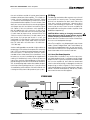
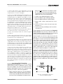
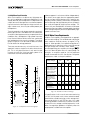
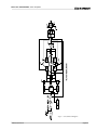
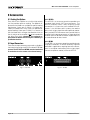
Micro-Tech 600/1200/2400 Power Amplifiers
5 Technical Information
5.1 Overview
Micro-Tech amplifiers incorporate several technological
advancements including real-time computer simulation
of output transistor stress, low-stress output stages and
an advanced heat sink embodiment.
Custom circuitry is incorporated to limit temperature
and current to safe levels making it highly reliable and
tolerant of faults. Unlike many lesser amplifiers, it can
operate at its voltage and current limits without self-destructing.
Micro-Tech amplifiers are protected from all common
hazards that plague high-power amplifiers including
shorted, open or mismatched loads; overloaded power
supplies; excessive temperature, chain-destruction
phenomenon, input overload and high-frequency blowups. The unit protects loudspeakers from input and output DC, as well as turn-on and turn-off transients.
Real-time computer simulation is used to create an analogue of the junction temperature of the output transistors (hereafter referred to as the output devices).
Current is limited only when the device temperature
becomes excessive—and only by the minimum
amount required). This patented approach called Output Device Emulation Protection (or ODEP) maximizes
the available output power and protects against overheating—the major cause of device failure.
Crown also invented the four-quadrant topology used
in the output stages of each Micro-Tech amplifier (see
Figure 5.1). This special circuitry is called the
Grounded Bridge. It makes full use of the power supply
by delivering peak-to-peak voltages to the load that are
twice the voltage seen by the output devices.
As its name suggests, the Grounded Bridge topology
is referenced to ground. Composite devices are constructed as gigantic NPN and PNP devices to handle
currents which exceed the limits of available devices.
Each output stage has two composite NPN devices and
two composite PNP devices.
The devices connected to the load are referred to as
“high-side NPN and PNP” and the devices connected
to ground are referred to as “low-side NPN and PNP.”
Positive current is delivered to the load by increasing
conductance simultaneously in the high-side NPN and
low-side PNP stage, while decreasing conductance of
the high-side PNP and low-side NPN.
The two channels may be used together to double the
voltage (Bridge-Mono) or current (Parallel-Mono) prePage 22
sented to the load. This feature gives you flexibility to
maximize power available to the load.
A wide bandwidth, multiloop design is used for state-ofthe-art compensation. This produces ideal behavior and
results in ultra-low distortion values.
Aluminum extrusions have been widely used for heat
sinks in power amplifiers due to their low cost and reasonable performance. But measured on a watts per
pound or watts per volume basis, the extrusion technology doesn’t perform nearly as well as the heat sink technology developed for Micro-Tech amplifiers.
The heat sinks in a Micro-Tech amplifier are fabricated
from custom convoluted fin stock that provides an extremely high ratio of area to volume, or area to weight.
All power devices are mounted directly to massive heat
spreaders that are electrically at the Vcc potential. Making the heat spreaders electrically alive improves thermal performance by eliminating the insulating interface
underneath each power device. The chassis itself is
also used as part of the thermal circuit to maximize utilization of the available resources.
5.2 Circuit Theory
Each channel is powered by its own power transformer
T100 or T200. Both channels share a common low-voltage supply. The secondary output of T100 is full-wave
rectified by D109 and is filtered by a large computer
grade capacitor. A thermal switch embedded in the
transformer protects it from overheating.
The low-voltage fanformer is rectified by diodes D1, D2, D3
and D4 to generate an unregulated 24 volts. Monolithic
regulators U1 and U2 provide a regulated ±15 volts.
5.2.1 Stereo Operation
For simplicity, the discussion of Stereo operation will refer to one channel only. Mono operation will be discussed later. For specific circuit references, see the
block diagram in Figure 5.1.
The signal at the ¼-inch phone jack input passes directly to the balanced gain stage (U104-A and U104-B).
The balanced gain stage causes balanced to singleended conversion using a difference amplifier. From
there, gain can be controlled with a potentiometer. The
error amp (U104-C) amplifies the difference between
the output signal and the input signal from the gain pot,
and drives the voltage translator stage.
From the error amp, the voltage translator stage routes
the signal to the Last Voltage Amplifiers (LVAs) based
on signal polarity. The +LVA (Q105) and the –LVA (Q110),
Reference Manual