1
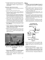
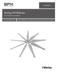
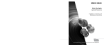
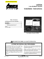
Available at Surplus Sales
LAC02A
®
Low Ambient Control
Installation Instructions
Table of Contents
ATTENTION INSTALLING PERSONNEL ............. 1
Description ............................................................ 2
Bill of Material ....................................................... 2
Installation ............................................................. 2
Units Without A High Pressure Control ............................ 2
Units With A High Pressure Control ................................ 3
Wiring ..................................................................... 3
Servicer’s Note ...................................................... 4
Low Ambient Control LAC02A
!
RECOGNIZE THIS SYMBOL AS A SAFETY PRECAUTION.
ATTENTION INSTALLING PERSONNEL
As a professional installer you have an obligation to
know the product better than the customer. This
includes all safety precautions and related items.
Remember, it is your responsibility to install the product
safely and to know it well enough to be able to instruct
a customer in its safe use.
Prior to actual installation, thoroughly familiarize
yourself with this Instruction Manual. Pay special
attention to all safety warnings. Often during installation
or repair it is possible to place yourself in a position
which is more hazardous than when the unit is in
operation.
Safety is a matter of common sense...a matter of
thinking before acting. Most dealers have a list of
specific good safety practices...follow them.
August 1999
The precautions listed in this Installation Manual should
not supersede existing practices but should be
considered as supplemental information.
Amana
Fayetteville, TN 37334
10664125
Description
2. Remove and save the control box cover.
This kit is for use with any Amana RCC, RCB, RCE, or
three-phase RCA/RCB and RCC remote cooling unit
which is installed with an indoor coil that includes a
thermal expansion valve. The Low Ambient Control kit
stops the outdoor fan on your unit when the high-side
pressure becomes too low. When the high-side pressure
rises, the outdoor fan will restart. This kit can only be
used with 208-230 volt units. Currently, remote cooling
units are only suitable for operation at outdoor temperatures of 50°F and above. The Low Ambient Control kit
allows these units to operate at outdoor ambients as
low as 35°F.
3. Remove and save the screws holding the control box
in place. Carefully swing the control box about 90°
counterclockwise.
IMPORTANT NOTE: If cooling operation at outdoor
ambients below 35°F, do not use this kit. Contact your
Amana distributor or branch office for assistance.
7. Before running the unit, perform a preliminary leak
check on the low ambient control. If a leak is found
tighten the connection slightly and retest.
IMPORTANT NOTE: Do not install this kit in a system
with an indoor coil and no thermal expansion valve.
Compressor damage could occur which would result in
voiding of your warranty.
8. Route the blue wires from the low ambient control
into the unit control box. To avoid equipment damage, route the wires so they avoid the fan.
Bill of Material
(1)
(1)
(1)
(1)
(1)
(2)
(1)
Refrigerant Tee,With Two Valve Cores
Low Ambient Cutout Control
Wire Nut
Low Ambient Label
Installation Instructions
Teflon Seals
Extension Tube
This kit should only be installed by a qualified, experienced technician.
Installation
WARNING
To avoid the risk of electrical shock,
injury, or death, disconnect the electrical
power before installing this kit.
4. Remove and discard the cap from the discharge line
access fitting.
5. Place a teflon seal in the fitting of the low ambient
control.
6. Install the low ambient control on the discharge line
access fitting. Tighten to 115 to 120 inch-pounds to
avoid refrigerant leaks. Use a backup wrench to
prevent damage to the fitting.
9. Carefully swing the control box clockwise to its
original position. Reattach it, using the screws
removed earlier.
Units Without A Discharge Tube Port
1. On RCB**B2A units, remove the screws holding the
service valve panel, control box cover, and control
box.
2. Swing out the control box, lift the service valve panel
up and out.
3. Remove and save the cap from the liquid line valve
schrader fitting. NOTE: It is not necessary to
remove the schrader core for a low ambient kit.
4. Prepare a connector tee in the kit by removing the
schrader core in the tee leg only. Connect the
extension tube in the kit to the tee connector where
the schrader core was removed. See Figure1 for the
tube and tee orientation. Do not connect the tee to
the liquid service valve until after the next step.
5. Place a teflon seal in the pressure switch fitting.
Install the pressure switch to the end of the extension
tube.
6. Locate the extension tube through the slot under the
liquid tube in the valve panel.
WARNING
To avoid possible injury from refrigerant,
wear gloves and goggles while installing
this kit.
7. Tighten the swivel nut on the tee on to the liquid valve
schrader port.
CAUTION
See the outdoor unit Installation Instructions for other
“Safe Refrigerant Handling” guidelines.
Refrigerant pressure is present during
connection. Take all necessary safety
precautions when installing this kit.
Units Without A High Pressure Control
1. Remove and save the screws holding the control box
cover in place.
8. Attach the schrader cap on the end of the tee.
9. Insert the blue switch wires through the bushing in
the back of the control box.
2
10. Carefully replace the service valve panel and screws.
Carefully swing the control box clockwise to it’s
original position. Reattach it using the screws removed earlier.
Units With A High Pressure Control
1. Remove and save the screws holding the control box
cover in place.
Wiring
1. Disconnect the Violet-20 fan motor lead (not the
compressor lead) from the contactor: terminal T2
on single-phase units, terminal T1 on three-phase
units.
2. Remove and save the control box cover.
2. The low ambient control includes a blue wire with a
straight female terminal. Install this wire on the
contactor: terminal T2 on single-phase units, terminal T1 on three phase units.
3. Remove and save the three screws holding the
control box in place. Carefully swing the control box
about 90° counterclockwise.
3. Locate the Violet-20 fan motor lead from step 1. Cut
off the terminal, and strip the insulation off the last
1/2 inch of the wire.
4. Using two wrenches to prevent the line from twisting,
remove the high pressure cutout from the high side
fitting. (The high pressure cutout has blue wires.) Do
not remove any wires from the high pressure cutout.
4. The low ambient control includes a blue wire with a
stripped end. Use the wire nut provided to attach
this wire to the Violet-20 wire from step 3. For an
adequate connection, pliers must be used to crimp
the wire nut onto the wires.
5. Place a teflon seal in the female opening of the
refrigerant tee. Install the refrigerant tee on the high
side access fitting. Using a backup wrench, tighten to
115 to 120 inch-pounds to avoid refrigerant leaks.
6. Reinstall the high pressure cutout on one end of the
tee. Tighten to 115 to120 inch-pounds to avoid
refrigerant leaks.
7. Place a teflon seal in the fitting of the low ambient
control. Install the low ambient control on the
remaining end of the tee. Tighten to 115 to 120 inchpounds to avoid refrigerant leaks.
8. Without running the unit, perform a preliminary leak
check on the tee, low ambient control, and the high
pressure cutout. If a leak is found, tighten the joint
slightly and recheck.
5. Using the low ambient label 10767901 as a guide,
inspect all wiring carefully. Confirm that all connections are tight and that no errors have been made.
Low Ambient Kit
Installed In This Unit
OUTDOOR FAN
MOTOR
MOTOR LEADS
CONNECTOR
VIOLET-20
(IF PRESENT)
WIRE NUT
LOW AMBIENT
CONTROL
EXTENSION TUBE
VAPOR LINE
SERVICE VALVE
T2 T1
L2 L1
CONTACTOR
Single Phase Unit Shown
Figure 2
6. Remove the backing from the low ambient label.
Without covering the unit wiring diagram, attach
the low ambient label on the inside of the control box
cover.
Service Valve with Extension Tube, Tee
and Cut-Out
Figure 1
9. Route the blue wires from the low ambient control
into the unit’s control box. To avoid equipment
damage, route the wires so they avoid the fan.
10. Carefully swing the control box clockwise to its
original position. Reattach it, using the screws
removed earlier.
3
7. Replace the control box cover.
8. When the system installation is complete, and the
outdoor temperature is 35°F or higher, run the
system to confirm proper operation: At compressor
startup, the outdoor fan will not initially run. The
outdoor fan will come on when the head pressure
rises to about 220 psi. During warm weather, the
outdoor fan will continue to run as long as the
compressor runs. During cool weather, the head
pressure will drop after the outdoor fan comes on. If
the head pressure drops to about 100 psi, the outdoor
fan will shut off. The head pressure will then begin
to rise. The outdoor fan will restart when the head
pressure rises to about 220 psi.
If any sparking, unusual odors, or unusual sounds are
noticed, immediately disconnect the electrical power
and check wiring and electrical components.
With the compressor running, it may be advisable to
perform a final leak check on the low ambient cutout and
nearby components. Before doing this, read the
“Servicer’s Note” section that follows.
Servicer’s Note
CAUTION
Avoid servicing the low ambient control
while the unit is operating. The rotating
fan blades could cause serious injury.
If measurement of the high side pressure is required, use
the liquid line valve on the outside of the unit. Also note
that most electrical measurements for the compressor
can be performed adequately near the contactor, rather
than at the compressor itself. If you must service the
area near the compressor or low ambient control with the
unit in operation, consider doing the following:
•
Disconnect the electrical power
•
Unplug the outdoor fan motor.
•
Carefully reconnect the electrical power.
• Operate the compressor only long enough to complete the needed service function.
NOTE: Running the system without outdoor airflow will
cause the head pressure to be substantially higher than
normal. Suction pressure and amp draw will also be
higher than normal. Subcooling, however, will be less
than normal.
4