1
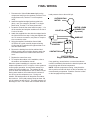
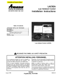
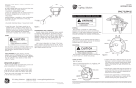
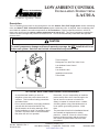
LOW AMBIENT CONTROL
INSTALLATION INSTRUCTIONS
Heating & Air Conditioning
®
LAC01A
C om fort. Q uality. Tru st.
Description
The Low Ambient Control LAC01A kit is designed for use with Amana® RCC, RCE single-phase remote condensing
units, and Amana® RCB, VCA and VCB three-phase remote condensing units. As shipped, these condensing units
are suitable for operation at outdoor temperatures of 50°F and above. Used in conjunction with the LAC01A kit,
these units can be used in outdoor ambient temperatures as low as 35°F. This control operates by stopping the
outdoor fan when the high side pressure becomes too low. The fan will automatically restart when the high side
pressure rises.
CAUTION
To avoid compressor damage and loss of warranty coverage, do NOT install this kit in an
indoor coil system that does not include a thermostatic expansion valve.
This kit includes:
Refrigerant Tee, With Two Valve Cores
Low Ambient Cutout Control
Wire Nut
Low Ambient Label
Installation Instructions
Teflon Seals
ATTENTION INSTALLING PERSONNEL
As a professional installer you have an
obligation to know the product better than the
customer. This includes all safety precautions
and related items.
Prior to actual installation, thoroughly familiarize
yourself with this Instruction Manual. Pay
special attention to all safety warnings. Often
during installation or repair it is possible to place
yourself in a position which is more hazardous
than when the unit is in operation.
Part No. 10664121 Rev. 1
Printed in USA
Remember, it is your responsibility to install the
product safely and to know it well enough to be
able to instruct a customer in its safe use.
Safety is a matter of common sense...a matter
of thinking before acting. Most dealers have a
list of specific good safety practices...follow
them.
The precautions listed in this Installation Manual
are intended as supplemental to existing
practices. However, if there is a direct conflict
between existing practices and the content of
this manual, the precautions listed here take
precedence.
Goodman Company, L.P.
1810 Wilson Parkway • Fayetteville, Tennessee 37334
www.amana-hac.com
November 2002
INSTALLATION INSTRUCTIONS
The LAC01A Kit is installed onto the unit discharge line fitting. To install, remove and set aside the control box cover
and screws. Carefully swing the control box cover 90° counterclockwise and follow the instructions below.
WARNING
To avoid the risk of electrical shock, injury, or death, disconnect the electrical power before
installing this kit.
WARNING
To avoid possible injury from refrigerant, wear gloves and goggles while installing this kit.
See the outdoor unit Installation Instructions for other “Safe Refrigerant Handling” guidelines.
RCC/RCE Single Phase Units
RCB, VCA and VCB Three- Phase Units
1. Remove and discard the discharge line fitting cap.
1. Using two wrenches to prevent the line from twisting,
disconnect the high pressure cutout from the discharge line fitting. Do not remove wires from the
high pressure cutout.
2. Place a teflon seal in the fitting of the low ambient
control.
3. Install the Low Ambient Control on the discharge line
fitting. Using a backup wrench, tighten to 115 - 120
inch-pounds to avoid refrigerant leaks.
2. Place a teflon seal in the female opening of the supplied refrigerant tee.
3. Install the refrigerant tee on the discharge line fitting.
Using a backup wrench, tighten to 115 - 120 inchpounds to avoid refrigerant leaks.
Without running the unit, perform a preliminary leak
check on the low ambient control. If a leak is found,
tighten the connection slightly and retest.
4. Reinstall the high pressure cutout on one end of the
tee. Tighten to 115 - 120 inch-pounds to avoid refrigerant leaks.
5. Place a teflon seal in the fitting of the low ambient
control. Install the Low Ambient Control on the remaining end of the tee. Tighten to 115 - 120 inchpounds to avoid refrigerant leaks.
Without running the unit, perform a preliminary leak
check on the tee, Low Ambient Control, and high
pressure cutout. If a leak is found, tighten the joint
slightly and retest.
Final Installation Step [All Units]
1. Route the blue wires from the low ambient control into the unit control box. To avoid equipment damage, route the wires so they avoid
the fan.
2. Carefully swing the control box clockwise to its original position. Reattach using the screws removed earlier.
2
FINAL WIRING
1. Disconnect the Violet-20 fan motor lead (not the
compressor lead) from the contactor (Terminal T2 on
single-phase units, Terminal T1 on three-phase
units).
head pressure rises to about 220 psi.
OUTDOOR FAN
MOTOR
2. Install the supplied straight female terminal wire
(blue), onto the contactor (Terminal T2 on singlephase units, Terminal T1 on three phase units.
3. Locate the Violet-20 fan motor lead from step 1. Cut
off the terminal, and strip the insulation off the last 1/
2 inch of the wire.
MOTOR LEADS
CONNECTOR
(If present)
VIOLET-20
4. Attach the supplied blue wire with the stripped end to
the Violet-20 wire from step 3 using the supplied wire
nut. For a secure connection, use pliers to crimp the
wire nut onto the wires.
WIRE NUT
5. Using the supplied Low Ambient Control label
10767901 as a guide, carefully inspect all wiring.
Confirm that all connections are tight and that no errors have been made.
LOW AMBIENT
CONTROL
T2 T1
L2 L1
6. Remove the backing from the low ambient label.
Without covering the unit wiring diagram, attach the
low ambient label on the inside of the control box
cover.
CONTACTOR
LAC01A Wiring
Single-Phase Unit Shown
7. Replace the control box cover.
8. To complete the outdoor unit’s installation, refer to
the outdoor unit installation manual.
If any sparking, unusual odors, or unusual sounds are
noticed, immediately disconnect the electrical power and
check wiring and electrical components.
When the system installation is complete, and the
outdoor temperature is 35°F or higher, run the system to
confirm proper operation: At compressor startup, the
outdoor fan will not initially run. The outdoor fan will
come on when the head pressure rises to about 220 psi.
During warm weather, the outdoor fan will continue to
run as long as the compressor runs. During cool
weather, the head pressure will drop after the outdoor
fan comes on. If the head pressure drops to about 100
psi, the outdoor fan will shut off. The head pressure will
then begin to rise. The outdoor fan will restart when the
NOTE: With the compressor running, it may be advisable to perform a final leak check on the low ambient cutout and nearby components. Read the “Servicer’s Note”
on the last page before proceeding.
3
SERVICER’S NOTE
CAUTION
Avoid servicing the low ambient control while the unit is operating. The rotating fan blades
could cause serious injury.
If measurement of the high side pressure is required, use the liquid line valve on the outside of the unit. Also note
that most electrical measurements for the compressor can be performed adequately near the contactor, rather than
at the compressor itself. If you must service the area near the compressor or low ambient control with the unit in
operation, consider doing the following:
a. Disconnect the electrical power
b. Unplug the outdoor fan motor.
c.
Carefully reconnect the electrical power.
d. Operate the compressor only long enough to complete the needed service function. Note that the lack of outdoor
airflow will cause the head pressure to be substantially higher than normal. Suction pressure and amp draw will
be higher than normal. Subcooling will be less than normal.
®
is a trademark of Maytag
Worldwide N.V. and is used under license to
Goodman Company, L.P. All rights reserved.
4