1
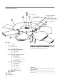
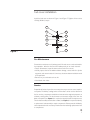
U S E R M A N UA L
Marley HP7000 fan
168" TH ROUG H 240" D IAM ETE R S
M01-1139B
I S S UE D 0 4 / 2013
R E A D A N D U N D E R S TAN D TH I S M AN UAL P R I O R TO O P E RATI N G OR S E RVI CI N G T H I S PR O D U CT.
fan components
122
121 150 ft·lbƒ (204 N·m)
101
HUB ASSEMBLY
IDENTIFICATION NUMBER
123
300
SEE FIG 6 FOR DETAILS
15 ft·lbƒ (20 N·m)
140 OUTBOARD ROW NOT REQD
ON 30" DIA. HUB ASSEMBLY
133 120 ft·lbƒ (163 N·m)
132
200
102
111
131
100Hub
101 Hub Center
102 Hub Plate
110 Kit–Blade Clamp
111
Blade Clamp
120 Kit–Center Hub Hardware
121
Cap Screw 5⁄8"
122
Flat Washer 5⁄8"
123
Pin 1⁄2"
130 Kit–Blade Clamp Hardware
131
Machine Bolt 3⁄4"
132 Flat Washer 3⁄4"
133 Locking Hex Nut 3⁄4" or
Hex Nut 3⁄4" and Lock Washer 3⁄4"
134
Thread Lubricant
140 Kit–Hub Cover Hardware
141
Machine Bolt 3⁄8"
142
Flat Washer 3⁄8"
143 Lock Washer 3⁄8"
144
Hex Nut 3⁄8"
145 Locking Hex Nut 3⁄8"
146
Spacer
150 Kit–Balance Hardware
160Manual
200Blade
300 Hub Cover
2
132
Figure 1—Typical Fan Assembly
actual component appearance may vary
Order No.________________________________________
Trial Pitch Angle___________________________________
Final Pitch Angle__________________________________
Speed-rpm_______________________________________
Contract hp______________________________________
fan hub installation
The following instructions detail the process for installing a Marley HP7000 Fan
on a Marley Geareducer® with a tapered fan (output) shaft and bolted fan hub
retention. Installation on other gear reduction units may be different. Contact
your Marley sales representative for supplemental instructions if required.
1 Remove the retention plate and hardware from the top of the Geareducer shaft.
Thoroughly clean the fan shaft, fan shaft key, and the fan hub center bore to
remove any debris and/or protective coatings. After cleaning, apply a coat of
anti-seize compound to the top 5" (130mm) of the fan shaft.
2 Prior to hub installation, fully seat the key in the fan shaft keyway. The key is
a tight fit across the width and must never be altered.
3 Raise the fan hub above the fan shaft for installation. Slowly lower the hub onto the
shaft with the keyways properly aligned. Make certain the key does not slide down
during installation. Stake the key in the keyway with a center punch if necessary.
The fan shaft key should be approximately centered in the engaged portion
of the hub when engaged on the shaft. Verify the center hub is fully seated
by visual inspection.
4 The hub retention plate will sit on top of the spool. Discard the retention bolts that come with the Geareducer. New retention bolts are
provided with the hub cover hardware kit. Torque bolts to 50 ft·lbƒ
(68 N·m).
Figure 2
3
fan blade installation
Marley HP7000 fan blades are manufactured to equal moment weight and
blade clamps to equal static weight. The blades and clamps can be installed in
any position without affecting fan balance.
Note
At the end of the blade shank on a nameplate is inscribed a letter
code (i.e. “A” or “B” etc.). When installing or replacing blades use
only blades with the same letter code.
HP7000 Fan
BLADE SIZE
MOMENT WEIGHT CLASS
SERIAL NUMBER
For Additional Information Refer to HP7000 Manual
SPX Cooling Technologies
Overland Park, KS USA
913 664 7400
www.spxcooling.com
Figure 3–Blade Nameplate
1 Lubricate the 3 ⁄4" bolt and 3 ⁄4" hex-nut threads with thread lubricant. Set the
hardware aside.
Figure 4
4
2 Remove one set of blade clamps from the hub assembly. Blade clamps are
installed on the hub assembly at the factory with spacers for shipping purposes. Remove and discard the spacers. Position the blade clamps around the
shank of a blade with the machined-face end of the blade clamp against the
blade safety shoulder. See Figure 5. Large nylon cable ties can be used to
hold blade clamps on the blade during installation providing easier assembly.
LOCKING HEX NUT OR
HEX NUT AND LOCK WASHER
FLAT WASHER
BLADE CLAMP
HUB PLATE
HUB PLATE
FLAT WASHER
Figure 5
FAN BLADE
MACHINE BOLT
3 I nsert the blade with blade clamps around the shank and with the concave blade
side (TOP) on the discharge side between the hub assembly plates as shown in
Figure 4. Vertically align the two bolt holes inthe clamps and plates. Install
two lubricated 3 ⁄4" bolts, four 3 ⁄4" flat washers, (two 3 ⁄4" lock washers if hardware material is monel), and two 3 ⁄4" hex nuts, engaging the nuts only three
to four threads as shown in Figure 5. Do not tighten the hardware until all
the blades have been installed. The blade must be free to rotate in the clamp
for pitch adjustment.
4 Repeat until all blades, clamps, and hardware have been installed in the hub
assembly.
5
adjusting fan blade pitch
Note
The trial pitch is the calculated setting for design conditions (water
rate , heat load, air density, and brake horsepower). The trial pitch
is provided by SPX Cooling Technologies (see page 2).
BLADE
TIP
STRAIGHT
EDGE
BEVEL
PROTRACTOR
PITCH ANGLE
Figure 6
2"
Section
1 Select a position on the fan circumference and rotate each blade to this common location when setting or checking blade pitch. Support the blade tip to
maintain a common rotation plane while setting the fan pitch. The pitch is set
within 2" (51mm) of the blade tip by placing a bevel protractor on top of a parallel sided straight edge that extends across blade width as shown in Figure 6.
2 Pull the blade outward so the safety shoulder is in contact with the blade clamp,
then set the pitch. See Figure 5. Blades should be within ± 1⁄4° of the desired
pitch angle. After the desired setting is obtained, progressively tighten the 3 ⁄4"
hex nuts to120 ft·lbƒ (163 N·m) torque. Recheck the pitch angle. If required,
loosen the hex nuts and reset the pitch as necessary until the proper pitch
angle is obtained with the 3 ⁄4" hex nuts at 120 ft·lbƒ (163 N·m) torque.
3 Repeat step 2 for all blades.
4 Check the vertical blade-tip track variation. The allowable vertical variation
from a reference plane is ±1" (25mm). If a blade’s tip track is out of tolerance,
loosen the 3 ⁄4" hardware and change the blade tip support location higher or
lower as required to adjust the tip track. Recheck blade pitch angle.
6
hub cover installation
Install the hub cover as shown in Figure 1 and Figure 7. Tighten all hex nuts to
15 ft·lbƒ (20 N·m) torque.
145
300
142
142
144
143
146
102
142
141
Figure 7
Fan Maintenance
Preventative maintenance will prolong useful life and assure continued troublefree operation. After the first week and subsequently at six month intervals:
• Torque all hardware to specifications referenced in this manual.
•V
isually inspect the fan for airborne debris damage, contact with fan cylinder
segments, and corrosive attack. Correct any situations determined detrimental
to fan operation.
• Remove any accumulated scale or dirt.
• Clear blade drain holes.
Service
Proper identification of your fan is necessary to insure you receive correct replacement parts. The Marley cooling tower serial number can be used to determine
the fan and any components installed and maintained as original equipment on
a Marley cooling tower. The fan diameter and moment weight class from the
blade nameplate (see Figure 3) is required to identify blades for replacement.
The fan hub assembly identification number (see Figure 1) is required to identify
a replacement hub assembly or repair components. Please provide the Marley
sales representative the necessary information when ordering replacement fans
or components.
➠
7
HP7000 fan
user manual
Blades can be replaced without rebalancing the entire fan.
If rebalancing is desired, contact the Marley sales representative in your area.
Motor Load
The corrected horsepower should be close to but not exceed the contract horsepower specified. Determine corrected horsepower using the following equation.
Actual volts and amperage must be obtained with the fan running and the
specified rate of water flowing over the tower after the motor and Geareducer
have reached operating temperature (approximately 30 minutes of operation).
HPC =
VOLTSA × AMPSA × DENSITYD
VOLTSN × AMPSN × DENSITYA
HPC
= Corrected Horsepower VOLTSN
= Nameplate Volts
VOLTSA
= Actual Volts
AMPSN
= Nameplate Amperage
AMPSA
= Actual Amperage
HPN
= Nameplate Horsepower
DENSITYA = Actual Air Density
Note
7401 W 129 STREET
OVERLAND PARK, KANSAS 66213 USA
P: 913 664 7400
F: 913 664 7439
[email protected]
In the interest of technological progress, all products are subject to design
and/or material change without notice
COPYRIGHT ©2013 SPX Corporation
DENSITYD = Design Air Density
Measurements taken on motors operating with Variable Frequency
Drive controls may read up to 15% high from errors in measuring
the approximated sine wave. Instruments capable of measuring a
squared off wave form accurately should be used for measuring
power in this situation.
Do not exceed 30 sec/hour total motor starting time as motor may
overheat.
S PX C O O L I N G T E C H N O LO G I E S , I N C .
ISSUED 04/2013 M92-1308A
× HPN